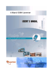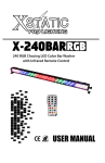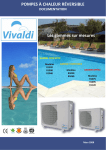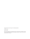
1
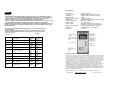
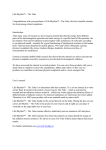
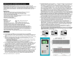
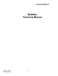
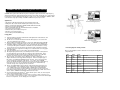
CORNET® ED-15C Electrosmog meter user’s manual
CORNET Microsystems ED-15 Electrosmog meter is designed for quick measurement of High frequency
(RF) Electromagnet wave field strength and power density level for living environments. It is excellent device
for individual or company with Electromagnetic wave safety concerns. It has bandwidth of 100MHz to 3GHz
useful detection range, high sensitivity of -55dBm to 0dBm and very fast response time.
Applications:
- High frequency (RF) Electromagnetic wave field strength measurement
- Mobile phone base station antenna radiation power density measurement
- Wireless communication applications (AM/FM, TDMA, GSM, DECT, CDMA)
- RF power measurement for transmitters
- Wireless LAN (Wi-Fi), Bluetooth, Ultra-wide-band detection, installation
- Spy camera, wireless bug finder
- Cellular/Cordless phone radiation safety level
- Microwave oven leakage detection
- Personal living environment EMF safety
Usage guide:
(1) Put the 9V battery in the ED15, Handle the ED15 with right hand in vertical direction, and
push the power switch button.
(2) The RF sensor is located in the left hand side of the ED15; please do not cover the RF
sensor area with hand or other objects.
(3) Measured RF field strength/power density is shown on the digital LCD display (with dBm
and uw/m2, mw/m²). 1st Push button can be used to select one of the two display mode.
(4) 8 LED lights. With Red, Yellow, and Green color on the right hand side of LCD window is
used for quick RF signal level indications.3 Red LEDs are used to indicate the 3 safety
range. The power level of each LED can be found in the table on the ED15 front panel.
(5) Histogram of previous 30 signal level readings are recorded and shown as moving graph
on the LCD display
(6) Bar segment display can be used for relative signal strength indication.
(7) Most high frequency RF antenna such as Mobile phone base station is vertical polarized
(in vertical direction), therefore the ED15 is normally used in vertical direction. Please
rotate the ED15 to find the maximum power reading direction to take care of RF wave
reflections. The ED15 can also be used to find the location of signal source.
(8) Most of modern communication devices (Mobile phone, Wireless LAN, Wi-Fi, etc.,) use
digital communication technology with burst RF signals. When measuring this type of
RF signals, several LED lights will blinking at the same time. This is normal and can be
used as an indication of burst type of RF signals. For continues waves (AM/FM)
signals, the LED light will stable. ED15 measures peak power density of signal with very
fast response time. It is more accurate than the needle style of readout which only
shown the average value of signal power most of the time.
(9) ED15 is a broadband High frequency (RF) type of Electrical field measuring device. It is
used for applications such as Mobile phone base station antenna radiation, Microwave
oven, Cellular/cordless phone, Radio transmitters, and WiFi wireless LAN installation
aid. It is not for low frequency magnetic field measurement (AC power Line, transformer,
high voltage power transmission line, motor ...) which should be measured with Gauss-meters
devices. Such as CORNET model ED25G RF/LF dual mode meters.
10) To get into the Hold mode, toggle the 2nd button under the power switch, the “Hold” sign will
show on the LCD display when in Hold mode.
11) To turn on/off the LCD back light, use 2nd push button to get into the “HOLD” mode first, then use
the 1st push button to toggle the LCD back light on and off. Remember to turn off the LCD backlight
when it is not required to save the battery power consumptions.
Field strength/power density readout:
ED15 use 8 high brightness LED to indicate the measured power density with 3
safety indications.
LED
color
Power
level
Power
density
Indication
RED3
-5 dBm
up
0.18 w/m2
Italy safety standard (0.1w/m2)
Caution!
RED2
-10 dBm
0.058 w/m2
Swiss safety standard (0.04w/m2)
Caution!
RED1
-15 dBm
0.018 w/m2
Russian safety standard(0.02w/m2)
Caution!
YELLOW3
-20 dBm
5.8 mw/m
YELLOW2
-25 dBm
1.8 mw/m
YELLOW1
-30 dBm
0.58 mw/m2
GREEN3
-35 dBm
0.18 mw/m
GREEN2
-40 dB
down
0.06 mw/m
Action
2
safe
2
safe
2
2
safe
WiFi Wireless LAN typically in this
range
safe
Some signal source around
safe
©2007 CORNET Microsystems all right reserved
Specification:
NOTE:
* Electromagnetic wave field strength/power density decades very fast with distance (distance
square), keep a good distance from the high frequency RF signal source can reduce the high
frequency radiation effect. Alumina foil or window sun reflector film (silver color) can be
used as a effective and low cost shielding material for most of RF radiations.
* ED15 is designed for quick living environment RF radiation evaluation and is for reference use
only. Official RF safety radiation measurement procedure is complicate and should be
handled by trained technical person with lab instruments. Safety range standard listed here is for
reference only. ED15 is not a medical instrument, Please do not use it in medical, legal or other
related applications.
The European Community provided general guidelines in its Council Recommendation of
July 1999.1 ICNIRP
published similar guidelines in April 1998.2 Table I gives a sampling of the international
and national field-strength limit values for the general public and continuous exposure
(for Reference only !)
Sensor type:
Frequency range:
Sensitivity:
Dynamic range:
Peak power measurement:
Display type:
Unit of measurements:
LCD back light:
Display of data:
Safety standard indication:
Battery used:
Battery life:
Electric field sensor
100MHz to 3GHz useful detection range
-55dBm to 0dBm (25mv/m to 14.8v/m)
60 dB
1.5uw/m² to 0.58w/m²
digital LCD display, LED color segment display
dBm, uw/m², mw/m², w/m²
15 seconds auto-off
LCD 3 and 5 digit, 8 LED color segment,
Histogram of 30 reading, LCD Bar segment
3 safety range indication by 3 Red LED
9V alkaline battery, (not included)
>20 hours
950Mhz
1850Mhz
International
Council Recommendation
1999/519/EC
Draft: National Quality Technology
Monitoring Bureau
42 V/m
(4.75W/m2)
42 V/m
(4.75W/m2)
49 V/m
(6.33W/m2)
21 V/m
(1.18W/m2)
42 V/m
(4.75W/m2)
6 V/m
(0.1W/m2)
20 V/m
(1W/m2)
51 V/m
(6.92W/m2)
4 V/m
(0.04W/m2)
49 V/m
(6.33W/m2)
49 V/m
(6.33W/m2)
59 V/m
(9.25W/m2)
59 V/m
(9.25W/m2)
61 V/m
(10W/m2)
30 V/m
(2.31W/m2)
59 V/m
(9.25W/m2)
6 V/m
(0.1W/m2)
20 V/m
(1W/m2)
83 V/m
(18W/m2)
6 V/m
(0.1W/m2)
68 V/m
(12W/m2)
61 V/m
(10W/m2)
International
ICNIRP Guidelines, April 1998
Austria
ÖNORM S1120
Belgium
Belgisch Staatsblad F.2001-1365
Germany
26. Deutsche Verordnung
Italy
Decreto n. 381, 1998
The
Netherlands
Health Council
Switzerland
Verordnung 1999
United States
IEEE C95.1
China
Japan
Radio-Radiation Protection
Guidelines, 1990
49 V/m
(6.33W/m2)
61 V/m
(10W/m2)
WARRANTY STATEMENT:
Cornet Microsystems guarantees that every instant CORNET ED15 product is free from physical defects
in material and workmanship under normal use for one (1) year from the date of purchase from Cornet
Microsystems or an authorized Cornet Microsystems agent. This warranty applies only to the original
purchaser and is not transferable. Proof of purchase will be required before any warranty consideration
by Cornet Microsystems occurs. This warranty does not cover any damage caused by negligence, nonauthorized modifications, or parts installed without prior written permission from Cornet Microsystems.
This warranty does not apply if the product has been damaged either by accident, misuse, or
misapplication, or as a result of service to the product by anyone other than Cornet Microsystems.
CORNET MICROSYSTEMS IS NOT RESPONSIBLE FOR ANY LOST PROFITS, LOST SAVINGS OR
OTHER INCIDENTIAL OR CONSEQUENTIAL DAMAGES ARISING OUT OF THE USE OF, OR
INABILITY TO USE, THIS PRODUCT. THIS INCLUDES DAMAGE TO PROPERTY AND, TO THE
EXTENT PERMITTED BY LAW, DAMAGES FOR PERSONAL INJURY. THIS WARRANTY IS IN LIEU
OF ALL OTHER WARRANTIES INCLUDING IMPLIED WARRANTIES OF MERCHANTABILITY AND
FITNESS FOR A PARTICULAR PURPOSE.
©2007 CORNET Microsystems Inc., 1400 Coleman Ave #C28 Santa Clara, CA 95050 USA
www.cornetmicro.com
ED15CV30L 07/07/2010
Tel: (408)9690205
Changes to CORNET Microsystems ED15C V.3.0L :
ED15C- 7/7/2010
Changes to CORNET Microsystems ED15C V.3.0L :
ED15C- 7/7/2010
CORNET ED-15 Revision 3.0L and up has additional improvements and new user’s interface. The changes
are in the followings:
CORNET ED-15 Revision 3.0L and up has additional improvements and new user’s interface. The changes
are in the followings:
Changes to Usage guide:
Changes to Usage guide:
(1)
(2)
(3)
(4)
(5)
New LCD Display modes:
There are two LCD display mode in the new Rev.3.0L meter. The 1st push button is used to
change the LCD display mode:
(a) Power meter display mode---see Fig.1, the signal level is displayed in dBm with big character
and the mw/m2 in small character, the Histogram display is larger.
(b) Field strength meter display mode----see Fig.2, the signal level is displayed in mW/m2 with big
character and the Max.signal level is displayed in the small character
Changes to the function of two push-button------ the 1st button is used to change the LCD
display mode. The 2nd push button is used to get into and exit the “HOLD” mode of the ED85EX
LCD display.
nd
Changes to the LCD back light control------ to turn on/off the LCD back light, use 2 push
button to get into the “HOLD” mode first, then use the 1st push button to toggle the LCD back light
nd
on and off. Get out of “HOLD” mode by pushing 2 button after the LCD back light setup.
Additional Max signal level display ------ in Field strength display mode, the Maximum signal
level (since meter Power on) is displayed below the current mW/m2 display line, the Max signal
level is excellent for recording the Max. Signal level while measuring around with the meter. To
reset the Max. Signal level; just get into the “HOLD” mode first by 2nd push button, the Max signal
level will be cleared when you exit the “HOLD” mode.
Improved Histogram display, the histogram display has been enlarged; the histogram will display
the 30 previous measurement data with moving graph.
Fig.1 power mode (dBm)
Fig.2 Field strength mode(mw/m2)
©2009 copyright CORNET Microsystem Inc all right reserved