1
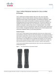
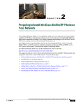
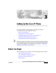
C H A P T E R
3
Setting Up the Cisco Unified IP Phone
This chapter includes the following topics, which help you install the
Cisco Unified IP Phones 7970G/7971G-GE on an IP telephony network:
Note
•
Before You Begin, page 3-2
•
Understanding the Cisco Unified IP Phone 7970G/7971G-GE Components,
page 3-5
•
Installing the Cisco Unified IP Phone, page 3-8
•
Adjusting the Placement of the Cisco Unified IP Phone, page 3-11
•
Verifying the Phone Startup Process, page 3-14
•
Configuring Startup Network Settings, page 3-16
•
Configuring Security on the Cisco Unified IP Phone, page 3-16
Before you install a Cisco Unified IP phone, you must make some critical
decisions about how to configure the phone in your network. You can then safely
install the phone and verify its functionality. For more information, see Chapter 2,
“Preparing to Install the Cisco Unified IP Phone on Your Network.”
Cisco Unified IP Phone Administration Guide for Cisco Unified CallManager 5.0 (SIP), Cisco Unified IP Phones
OL-8182-01
3-1
Chapter 3
Setting Up the Cisco Unified IP Phone
Before You Begin
Before You Begin
Before installing the Cisco Unified IP Phone, review the requirements in these
sections:
•
Network Requirements, page 3-2
•
Cisco Unified CallManager Configuration, page 3-2
•
Safety, page 3-3
Network Requirements
For the Cisco Unified IP Phones 7970G/7971G-GE to successfully operate as a
Cisco Unified IP Phone endpoint in your network, your network must meet these
requirements:
•
Working Voice over IP (VoIP) Network:
– VoIP configured on your Cisco routers and gateways
– Cisco Unified CallManager Release 5.x or higher installed in your
network and configured to handle call processing
•
Note
IP network that supports DHCP or manual assignment of IP address, gateway,
and subnet mask
The Cisco Unified IP Phone displays the date and time from Cisco Unified
CallManager. If the Cisco Unified CallManager server is located in a different
time zone than the phones, the phones will not display the correct local time.
Cisco Unified CallManager Configuration
The Cisco Unified IP Phone requires Cisco Unified CallManager to handle call
processing. Refer to Cisco Unified CallManager Administration Guide or
context-sensitive help in the Cisco Unified CallManager application to ensure
that Cisco Unified CallManager is set up properly to manage the phone and to
properly route and process calls.
3-2
Cisco Unified IP Phone Administration Guide for Cisco Unified CallManager 5.0 (SIP), Cisco Unified IP Phones
OL-8182-01
Chapter 3
Setting Up the Cisco Unified IP Phone
Before You Begin
If you plan to use auto-registration, verify that it is enabled and properly
configured in Cisco Unified CallManager before connecting any
Cisco Unified IP Phone to the network. For information about enabling and
configuring auto-registration, refer to Cisco Unified CallManager Administration
Guide. Also, see the “Adding Phones to the Cisco Unified CallManager
Database” section on page 2-13.
You must use Cisco Unified CallManager to configure and assign telephony
features to the Cisco Unified IP Phones. See the “Telephony Features Available
for the Phone” section on page 5-2 for details.
In Cisco Unified CallManager, you can add users to the database and associate
them with specific phones. In this way, users gain access to web pages that allow
them to configure items such as call forwarding, speed dialing, and voice
messaging system options. See the “Adding Users to Cisco Unified CallManager”
section on page 5-16 for details.
Safety
Review the following warnings before installing the
Cisco Unified IP Phone 7970. To see translations of these warnings, refer to the
Regulatory Compliance and Safety Information for the Cisco Unified IP Phone
7900 Series document that accompanied this device.
Warning
Read the installation instructions before you connect the system to its power
source.
Warning
Only trained and qualified personnel should be allowed to install, replace, or
service this equipment.
Warning
Ultimate disposal of this product should be handled according to all national
laws and regulations.
Cisco Unified IP Phone Administration Guide for Cisco Unified CallManager 5.0 (SIP), Cisco Unified IP Phones
OL-8182-01
3-3
Chapter 3
Setting Up the Cisco Unified IP Phone
Before You Begin
Warning
Do not work on the system or connect or disconnect cables during periods of
lightning activity.
Warning
To avoid electric shock, do not connect safety extra low voltage (SELV) circuits
to telephone network voltage (TNV) circuits. LAN ports contain SELV circuits,
and WAN ports contain TNV circuits. Some LAN and WAN ports both use RJ-45
connectors. Use caution when connecting cables.
Caution
Inline power circuits provide current over the cable. Use the Cisco provided cable
or a minimum 24 AWG communication cable.
The following warnings apply when you use an external power supply.
Caution
3-4
Only use the proper Cisco approved external power supply. Reference the
installation manual provided with the phone.
Warning
This product relies on the building's installation for short-circuit (overcurrent)
protection. Ensure that a fuse or circuit breaker no larger than 120 VAC, 15 A U.S.
(240 VAC, 10 A international) is used on the phase conductors (all
current-carrying conductors).
Warning
The device is designed to work with TN power systems.
Warning
The plug-socket combination must be accessible at all times because it serves
as the main disconnecting device.
Cisco Unified IP Phone Administration Guide for Cisco Unified CallManager 5.0 (SIP), Cisco Unified IP Phones
OL-8182-01
Chapter 3
Setting Up the Cisco Unified IP Phone
Understanding the Cisco Unified IP Phone 7970G/7971G-GE Components
Understanding the Cisco Unified IP Phone
7970G/7971G-GE Components
The Cisco Unified IP Phone 7970G/7971G-GE includes these components on the
phone or as accessories for the phone:
•
Network and Access Ports, page 3-5
•
Handset, page 3-5
•
Speakerphone, page 3-6
•
Headset, page 3-6
Network and Access Ports
The back of the Cisco Unified IP Phone 7970G/7971G-GE includes these ports:
•
Network port—Labeled 10/100 SW on the Cisco Unified IP Phone 7970G
and 10/100/1000 SW on the Cisco Unified IP Phone 7971G-GE
•
Access port—Labeled 10/100 PC on the Cisco Unified IP Phone 7970G and
10/100/1000 PC on the Cisco Unified IP Phone 7971G-GE
Each port supports 10/100 or 10/100/1000 Mbps half- or full-duplex connections
to external devices. You can use either Category 3 or 5 cabling for 10-Mbps
connections, but you must use Category 5 for 100 and 1000 Mbps connections.
Use the SW network port to connect the phone to the network. You must use a
straight-through cable on this port. The phone can also obtain inline power from
a switch over this connection. See the “Providing Power to the Phone” section on
page 2-4 for details.
Use the PC access port to connect a network device, such as a computer, to the
phone. You must use a straight-through cable on this port.
Handset
The handset is designed especially for use with a Cisco Unified IP Phone. It
includes a light strip that indicates incoming calls and voice messages waiting.
Cisco Unified IP Phone Administration Guide for Cisco Unified CallManager 5.0 (SIP), Cisco Unified IP Phones
OL-8182-01
3-5
Chapter 3
Setting Up the Cisco Unified IP Phone
Understanding the Cisco Unified IP Phone 7970G/7971G-GE Components
Speakerphone
By default, the speakerphone is enabled on Cisco Unified IP Phones
7970G/7971G-GE.
You can disable the speakerphone through the Cisco Unified CallManager
Administration application. To do so, choose Device > Phone and locate the
phone you want to modify. In the Phone Configuration web page for the phone,
check the Disable Speakerphone check box.
Headset
Although Cisco Systems performs some internal testing of third-party headsets
for use with the Cisco Unified IP Phones, Cisco does not certify or support
products from headset or handset vendors. Because of the inherent environmental
and hardware inconsistencies in the locations where Cisco Unified IP Phones are
deployed, there is not a single “best” solution that is optimal for all environments.
Cisco recommends that customers test the headsets that work best in their
environment before deploying a large number of units in their network.
In some instances, the mechanics or electronics of various headsets can cause
remote parties to hear an echo of their own voice when they speak to
Cisco Unified IP Phone users.
Cisco Systems recommends the use of good quality headsets that are screened
against unwanted radio frequency (RF) and audio frequency (AF) signals.
Depending on the quality of headsets and their proximity to other devices such as
cell phones and two-way radios, some audio noise may still occur.
The primary reason that support of a headset would be inappropriate for an
installation is the potential for an audible hum. This hum can either be heard by
the remote party or by both the remote party and the Cisco Unified IP Phone user.
Some potential humming or buzzing sounds can be caused by a range of outside
sources, for example, electric lights, being near electric motors, large PC
monitors. In some cases, a hum experienced by a user may be reduced or
eliminated by using a local power cube (CP-PWR-CUBE-3). See the “Safety”
section on page 3-3 for more information.
3-6
Cisco Unified IP Phone Administration Guide for Cisco Unified CallManager 5.0 (SIP), Cisco Unified IP Phones
OL-8182-01
Chapter 3
Setting Up the Cisco Unified IP Phone
Understanding the Cisco Unified IP Phone 7970G/7971G-GE Components
Audio Quality Subjective to the User
Beyond the physical, mechanical and technical performance, the audio portion of
a headset must sound good to the user and the party on the far end. Sound is
subjective and Cisco cannot guarantee the performance of any headsets or
handsets, but some of the headsets and handsets on the sites listed below have
been reported to perform well on Cisco Unified IP Phones.
Nevertheless, it is ultimately still the customer’s responsibility to test this
equipment in their own environment to determine suitable performance.
For information about headsets, see:
http://vxicorp.com/cisco
http://plantronics.com
Connecting a Headset
To connect a headset to the Cisco Unified IP Phone, plug it into the Headset port
on the back of the phone. Press the Headset button on the phone to place and
answer calls using the headset.
You can use the headset with all of the features on the Cisco Unified IP Phone,
including the Volume and Mute buttons. Use these buttons to adjust the ear piece
volume and to mute the speech path from the headset microphone.
Disabling a Headset
You can disable the headset through the Cisco Unified CallManager
Administration application. If you do so, you also will disable the speakerphone.
To disable the headset from Cisco Unified CallManager Administration, choose
Device > Phone and locate the phone that you want to modify. In the Phone
Configuration web page for the phone, check the Disable Speakerphone and
Headset check box.
Cisco Unified IP Phone Administration Guide for Cisco Unified CallManager 5.0 (SIP), Cisco Unified IP Phones
OL-8182-01
3-7
Chapter 3
Setting Up the Cisco Unified IP Phone
Installing the Cisco Unified IP Phone
Using External Devices with Your Cisco Unified IP Phone
The following information applies when you use external devices with the
Cisco Unified IP Phone:
Cisco recommends the use of good quality external devices (speakers,
microphones, and headsets) that are shielded (screened) against unwanted radio
frequency (RF) and audio frequency (AF) signals.
Depending on the quality of these devices and their proximity to other devices
such as mobile phones or two-way radios, some audio noise may still occur. In
these cases, Cisco recommends that you take one or more of the following actions:
•
Move the external device away from the source of the RF or AF signals.
•
Route the external device cables away from the source of the RF or AF
signals.
•
Use shielded cables for the external device, or use cables with a better shield
and connector.
•
Shorten the length of the external device cable.
•
Apply ferrites or other such devices on the cables for the external device.
Cisco cannot guarantee the performance of the system because Cisco has no
control over the quality of external devices, cables, and connectors. The system
will perform adequately when suitable devices are attached using good quality
cables and connectors.
Caution
In European Union countries, use only external speakers, microphones, and
headsets that are fully compliant with the EMC Directive [89/336/EC].
Installing the Cisco Unified IP Phone
You must connect the Cisco Unified IP Phone to the network and to a power
source before using it. See Figure 3-1 for a graphical representation of the
connections.
Note
3-8
Before you install a phone, even if it is new, upgrade the phone to the current
firmware image.
Cisco Unified IP Phone Administration Guide for Cisco Unified CallManager 5.0 (SIP), Cisco Unified IP Phones
OL-8182-01
Chapter 3
Setting Up the Cisco Unified IP Phone
Installing the Cisco Unified IP Phone
Note
Before using external devices, read the “Using External Devices with Your Cisco
Unified IP Phone” section on page 3-8 for safety and performance information.
To install a Cisco Unified IP Phone, perform the following steps:
Procedure
Notes
Reference
—
1.
Connect the handset to the
Handset port.
—
2.
Connect a headset to the
Headset port.
Optional. You can add a headset See the “Headset” section on
later if you do not connect one
page 3-6 for supported headsets.
now.
3.
Connect the power supply to Optional.
the Cisco DC Adapter port.
See the “Providing Power to the
Phone” section on page 2-4.
4.
Each Cisco Unified IP Phone
Connect a Category 3 or 5
ships with one Ethernet cable in
straight-through Ethernet
cable from the switch to the the box.
10/100 SW port (Cisco
Unified IP Phone 7970) or
the 10/100/1000 SW port
(Cisco Unified IP Phone
7971G-GE).
See the “Network and Access
Ports” section on page 3-5 for
guidelines.
5.
Optional. You can connect
Connect a Category 3 or 5
another network device later if
straight-through Ethernet
cable from another network you do not connect one now.
device, such as a desktop
computer, to the 10/100 PC
port (Cisco Unified
IP Phone 7970) or the
10/100/1000 PC port (Cisco
Unified IP Phone
7971G-GE).
See the “Network and Access
Ports” section on page 3-5 for
guidelines.
Cisco Unified IP Phone Administration Guide for Cisco Unified CallManager 5.0 (SIP), Cisco Unified IP Phones
OL-8182-01
3-9
Chapter 3
Setting Up the Cisco Unified IP Phone
Installing the Cisco Unified IP Phone
Figure 3-1
Cisco Unified IP Phones 7970G/7971G-GE Rear Cable Connections
1
AUX
10/100/1000 SW 10/100/1000 PC
DC48V
3
7
2
130055
6
5
4
1
DC adapter port (DC48V)
5
Access port (1000 appears on the Cisco
Unified IP Phone 7971G-GE only)
2
Power supply with DC Connector
6
Handset port
3
Power cable with AC wall plug
7
Headset port
4
Network port (1000 appears on the Cisco
Unified IP Phone 7971G-GE only)
3-10
Cisco Unified IP Phone Administration Guide for Cisco Unified CallManager 5.0 (SIP), Cisco Unified IP Phones
OL-8182-01
Chapter 3
Setting Up the Cisco Unified IP Phone
Adjusting the Placement of the Cisco Unified IP Phone
Related Topics
•
Before You Begin, page 3-2
•
Adjusting the Placement of the Cisco Unified IP Phone, page 3-11
•
Configuring Startup Network Settings, page 3-16
Adjusting the Placement of the Cisco Unified IP
Phone
The Cisco Unified IP Phone includes an adjustable footstand. When placing the
phone on a desktop surface, you can adjust the tilt height to several different
angles in 7.5 degree increments from flat to 60 degrees. You can also mount the
phone to the wall using the footstand or using the optional locking wall mount kit.
Adjusting Cisco Unified IP Phone Placement on the Desktop
To adjust the footstand on the Cisco Unified IP Phone to the height that provides
optimum viewing of the LCD screen, follow these steps:
Procedure
Step 1
Push in the footstand adjustment button.
Step 2
Adjust the footstand to the desired height.
Cisco Unified IP Phone Administration Guide for Cisco Unified CallManager 5.0 (SIP), Cisco Unified IP Phones
OL-8182-01
3-11
Chapter 3
Setting Up the Cisco Unified IP Phone
Adjusting the Placement of the Cisco Unified IP Phone
Securing the Phone with a Cable Lock
You can secure the Cisco Unified IP Phone 7970G/7971G-GE to a desktop using
a laptop cable lock. The lock connects to the security slot on the back of the phone
and the cable can be secured to a desktop.
The security slot can accommodate a lock up to 20 mm. Compatible laptop cable
locks include the Kensington® laptop cable lock and laptop cable locks from
other manufacturers that can fit into the security slot on the back of the phone.
See Figure 3-2 below.
Connecting a Cable Lock to the Cisco Unified IP Phone
7970G/7971G-GE
144478
Figure 3-2
3-12
Cisco Unified IP Phone Administration Guide for Cisco Unified CallManager 5.0 (SIP), Cisco Unified IP Phones
OL-8182-01
Chapter 3
Setting Up the Cisco Unified IP Phone
Adjusting the Placement of the Cisco Unified IP Phone
Mounting the Phone to the Wall
You can mount the Cisco Unified IP Phone on the wall using the footstand as a
mounting bracket or you can use special brackets available in a Cisco Unified IP
Phone wall mount kit. (Wall mount kits must be ordered separately from the
phones.) If you attach the phone to a wall using the standard footstand and not the
wall mount kit, you need to supply the following tools and parts:
•
Screwdriver
•
Screws to secure the Cisco Unified IP phone to the wall
Use the following procedure to mount the phone on the wall using the standard
footstand. See Figure 3-3 for a graphical overview of this procedure.
Before You Begin
To ensure that the handset attaches securely to a wall-mounted phone, remove the
handset wall hook from the handset rest, rotate the hook 180 degrees, and reinsert
the hook. Turning the hook exposes a lip on which the handset catches when the
phone is vertical. For an illustrated procedure, see Installing the Wall Mount Kit
for the Cisco Unified IP Phone.
Caution
Use care not to damage wires or pipes located inside the wall when securing
screws to wall studs.
Procedure
Step 1
Push in the footstand adjustment button.
Step 2
Adjust the footstand so it is flat against the back of the phone.
Step 3
Insert two screws into a wall stud, matching them to the two screw holes on the
back of the footstand.
The keyholes fit standard phone jack mounts.
Step 4
Hang the phone on the wall.
Cisco Unified IP Phone Administration Guide for Cisco Unified CallManager 5.0 (SIP), Cisco Unified IP Phones
OL-8182-01
3-13
Chapter 3
Setting Up the Cisco Unified IP Phone
Verifying the Phone Startup Process
Figure 3-3
Parts Used in Wall Mounting the Cisco Unified IP Phone
1
Footstand adjustment button—Raises and lowers adjustment plate
2
Wall mounting screw holes
3
Adjustment plate—Raises and lowers phone vertically
Verifying the Phone Startup Process
After the Cisco Unified IP Phone has power connected to it, the phone begins its
startup process by cycling through the following steps.
1.
These buttons flash on and off in sequence:
– Headset. (Only if the handset is off-hook when the phone powers up. In
this case, hang up the handset within 3 seconds or the phone launches its
secondary load instead of its primary load.)
– Mute.
– Speaker.
3-14
Cisco Unified IP Phone Administration Guide for Cisco Unified CallManager 5.0 (SIP), Cisco Unified IP Phones
OL-8182-01
Chapter 3
Setting Up the Cisco Unified IP Phone
Verifying the Phone Startup Process
2.
Caution
Some or all of the line keys flash orange.
If the line keys flash red in sequence after flashing yellow, do not power down the
phone until the sequence of red flashes completes. This sequence can take several
minutes to complete.
3.
Some or all of the line keys flash green.
Normally, this sequence takes just a few seconds. However, if the phone’s
Flash memory is erased or the phone load is corrupted, the sequence of green
flashes will continue while the phone begins a software update procedure. If
the phone performs this procedure, the following buttons light to indicate
progress:
– Headset—Phone is waiting for the network and completing CDP and
DHCP configuration. (A DHCP server must be available in your
network.)
– Mute—Phone is downloading images from the TFTP server.
– Speaker—Phone is writing images to its Flash memory.
4.
The LCD screen displays the Cisco Systems, Inc., logo screen.
5.
These messages appear as the phone starts:
– Verifying load (if the phone load does not match the load on the TFTP
server). If this message appears, the phone start up again and repeats step
1 through step 4 above.
– Configuring IP.
– Updating CTL.
– Updating Locale.
– Configuring CM List.
– Registering.
Cisco Unified IP Phone Administration Guide for Cisco Unified CallManager 5.0 (SIP), Cisco Unified IP Phones
OL-8182-01
3-15
Chapter 3
Setting Up the Cisco Unified IP Phone
Configuring Startup Network Settings
6.
The main LCD screen displays:
– Current date and time
– Primary directory number
– Additional directory numbers and speed dial numbers, if configured
– Softkeys
If the phone successfully passes through these stages, it has started up properly.
If the phone does not start up properly, see the “Resolving Startup Problems”
section on page 9-2.
Configuring Startup Network Settings
If you are not using DHCP in your network, you must configure these network
settings on the Cisco Unified IP Phone after installing the phone on the network:
•
IP address
•
IP subnet mask
•
Default gateway IP address
•
TFTP server IP address
You may also configure these optional settings as necessary:
•
Domain name
•
DNS server IP address
Collect this information and see the instructions in Chapter 4, “Configuring
Settings on the Cisco Unified IP Phone.”
Configuring Security on the Cisco Unified IP Phone
The security features protect against several threats, including threats to the
identity of the phone and to data. These features establish and maintain
authenticated communication streams between the phone and the
Cisco Unified CallManager server, and digitally sign files before they are
delivered.
3-16
Cisco Unified IP Phone Administration Guide for Cisco Unified CallManager 5.0 (SIP), Cisco Unified IP Phones
OL-8182-01
Chapter 3
Setting Up the Cisco Unified IP Phone
Configuring Security on the Cisco Unified IP Phone
For more information about the security features, see the “Understanding Security
Features for Cisco Unified IP Phones” section on page 1-12. Also, refer to Cisco
Unified CallManager Security Guide.
A Locally Significant Certificate (LSC) installs on phones after you perform the
necessary tasks that are associated with the CAPF. You can use
Cisco Unified CallManager Administration to configure an LSC, as described in
Cisco Unified CallManager Security Guide. Alternatively, you can initiate the
installation of an LSC from the Security Configuration menu on the phone. This
menu also lets you update or remove an LSC.
Alternatively, you can initiate the installation of an LSC from the Security
Configuration menu on the phone. This menu also lets you update or remove an
LSC.
Before You Begin
Make sure that the appropriate Cisco Unified CallManager and the Certificate
Authority Proxy Function (CAPF) security configurations are complete:
•
The CTL file should have a CAPF certificate.
•
The CAPF certificate must exist in the C:\Program Files\Cisco\Certificates
folder in every server in the cluster.
•
The CAPF is running and configured.
Refer to Cisco Unified CallManager Security Guide for more information.
Note
Depending on how you have configured the CAPF, this procedure installs an LSC,
updates an existing LSC, or removes an existing LSC.
To configure an LSC on the phone, perform the following steps.
Cisco Unified IP Phone Administration Guide for Cisco Unified CallManager 5.0 (SIP), Cisco Unified IP Phones
OL-8182-01
3-17
Chapter 3
Setting Up the Cisco Unified IP Phone
Configuring Security on the Cisco Unified IP Phone
Procedure
Step 1
Obtain the CAPF authentication string that was set when the CAPF was
configured.
Step 2
From the phone, press the Settings > Security Configuration.
Note
You can control access to the Settings Menu by using the Settings Access
field in the Cisco Unified CallManager Administration Phone
Configuration Settings page. For more information, see Cisco
Unified CallManager Administration Guide.
Step 3
Press **# to unlock settings on the Security Configuration menu.
Step 4
Scroll to LSC and press the Update softkey.
The phone prompts for an authentication string.
Step 5
Enter the authentication code and press the Submit softkey.
The phone begins to install, update, or remove the LSC, depending on how the
CAPF was configured. During the procedure, a series of messages appears in the
LSC option field in the Security Configuration menu so that you can monitor
progress. When the procedure completes successfully, the phone will display
Installed or Not Installed.
The LSC install, update, or removal process can take a long time to complete. You
can stop the process at any time by pressing the Stop softkey from the Security
Configuration menu. (Settings must be unlocked before you can press this
softkey.)
When the phone successfully completes the installation procedure, it displays
“Success.” If the phone displays, “Failure,” the authorization string may be
incorrect or the phone may not enabled for upgrading. Refer to error messages
generated by the CAPF and take appropriate actions.
You can verify that an LSC is installed on the phone by choosing Settings >
Model Information and ensuring that the LSC setting shows Installed.
Related Topic
•
3-18
Understanding Security Features for Cisco Unified IP Phones, page 1-12
Cisco Unified IP Phone Administration Guide for Cisco Unified CallManager 5.0 (SIP), Cisco Unified IP Phones
OL-8182-01