1
Catalyst 3550 Multilayer Switch
Hardware Installation Guide
November 2004
Corporate Headquarters
Cisco Systems, Inc.
170 West Tasman Drive
San Jose, CA 95134-1706
USA
http://www.cisco.com
Tel: 408 526-4000
800 553-NETS (6387)
Fax: 408 526-4100
Text Part Number: OL-6155-01
THE SPECIFICATIONS AND INFORMATION REGARDING THE PRODUCTS IN THIS MANUAL ARE SUBJECT TO CHANGE WITHOUT NOTICE. ALL
STATEMENTS, INFORMATION, AND RECOMMENDATIONS IN THIS MANUAL ARE BELIEVED TO BE ACCURATE BUT ARE PRESENTED WITHOUT
WARRANTY OF ANY KIND, EXPRESS OR IMPLIED. USERS MUST TAKE FULL RESPONSIBILITY FOR THEIR APPLICATION OF ANY PRODUCTS.
THE SOFTWARE LICENSE AND LIMITED WARRANTY FOR THE ACCOMPANYING PRODUCT ARE SET FORTH IN THE INFORMATION PACKET THAT
SHIPPED WITH THE PRODUCT AND ARE INCORPORATED HEREIN BY THIS REFERENCE. IF YOU ARE UNABLE TO LOCATE THE SOFTWARE LICENSE
OR LIMITED WARRANTY, CONTACT YOUR CISCO REPRESENTATIVE FOR A COPY.
The following information is for FCC compliance of Class A devices: This equipment has been tested and found to comply with the limits for a Class A digital device, pursuant
to part 15 of the FCC rules. These limits are designed to provide reasonable protection against harmful interference when the equipment is operated in a commercial
environment. This equipment generates, uses, and can radiate radio-frequency energy and, if not installed and used in accordance with the instruction manual, may cause
harmful interference to radio communications. Operation of this equipment in a residential area is likely to cause harmful interference, in which case users will be required
to correct the interference at their own expense.
The following information is for FCC compliance of Class B devices: The equipment described in this manual generates and may radiate radio-frequency energy. If it is not
installed in accordance with Cisco’s installation instructions, it may cause interference with radio and television reception. This equipment has been tested and found to
comply with the limits for a Class B digital device in accordance with the specifications in part 15 of the FCC rules. These specifications are designed to provide reasonable
protection against such interference in a residential installation. However, there is no guarantee that interference will not occur in a particular installation.
Modifying the equipment without Cisco’s written authorization may result in the equipment no longer complying with FCC requirements for Class A or Class B digital
devices. In that event, your right to use the equipment may be limited by FCC regulations, and you may be required to correct any interference to radio or television
communications at your own expense.
You can determine whether your equipment is causing interference by turning it off. If the interference stops, it was probably caused by the Cisco equipment or one of its
peripheral devices. If the equipment causes interference to radio or television reception, try to correct the interference by using one or more of the following measures:
• Turn the television or radio antenna until the interference stops.
• Move the equipment to one side or the other of the television or radio.
• Move the equipment farther away from the television or radio.
• Plug the equipment into an outlet that is on a different circuit from the television or radio. (That is, make certain the equipment and the television or radio are on circuits
controlled by different circuit breakers or fuses.)
Modifications to this product not authorized by Cisco Systems, Inc. could void the FCC approval and negate your authority to operate the product.
The Cisco implementation of TCP header compression is an adaptation of a program developed by the University of California, Berkeley (UCB) as part of UCB’s public
domain version of the UNIX operating system. All rights reserved. Copyright © 1981, Regents of the University of California.
NOTWITHSTANDING ANY OTHER WARRANTY HEREIN, ALL DOCUMENT FILES AND SOFTWARE OF THESE SUPPLIERS ARE PROVIDED “AS IS” WITH
ALL FAULTS. CISCO AND THE ABOVE-NAMED SUPPLIERS DISCLAIM ALL WARRANTIES, EXPRESSED OR IMPLIED, INCLUDING, WITHOUT
LIMITATION, THOSE OF MERCHANTABILITY, FITNESS FOR A PARTICULAR PURPOSE AND NONINFRINGEMENT OR ARISING FROM A COURSE OF
DEALING, USAGE, OR TRADE PRACTICE.
IN NO EVENT SHALL CISCO OR ITS SUPPLIERS BE LIABLE FOR ANY INDIRECT, SPECIAL, CONSEQUENTIAL, OR INCIDENTAL DAMAGES, INCLUDING,
WITHOUT LIMITATION, LOST PROFITS OR LOSS OR DAMAGE TO DATA ARISING OUT OF THE USE OR INABILITY TO USE THIS MANUAL, EVEN IF CISCO
OR ITS SUPPLIERS HAVE BEEN ADVISED OF THE POSSIBILITY OF SUCH DAMAGES.
CCSP, the Cisco Square Bridge logo, Cisco Unity, Follow Me Browsing, FormShare, and StackWise are trademarks of Cisco Systems, Inc.; Changing the Way We Work,
Live, Play, and Learn, and iQuick Study are service marks of Cisco Systems, Inc.; and Aironet, ASIST, BPX, Catalyst, CCDA, CCDP, CCIE, CCIP, CCNA, CCNP, Cisco,
the Cisco Certified Internetwork Expert logo, Cisco IOS, Cisco Press, Cisco Systems, Cisco Systems Capital, the Cisco Systems logo, Empowering the Internet Generation,
Enterprise/Solver, EtherChannel, EtherFast, EtherSwitch, Fast Step, GigaDrive, GigaStack, HomeLink, Internet Quotient, IOS, IP/TV, iQ Expertise, the iQ logo, iQ Net
Readiness Scorecard, LightStream, Linksys, MeetingPlace, MGX, the Networkers logo, Networking Academy, Network Registrar, Packet, PIX, Post-Routing, Pre-Routing,
ProConnect, RateMUX, Registrar, ScriptShare, SlideCast, SMARTnet, StrataView Plus, SwitchProbe, TeleRouter, The Fastest Way to Increase Your Internet Quotient,
TransPath, and VCO are registered trademarks of Cisco Systems, Inc. and/or its affiliates in the United States and certain other countries.
All other trademarks mentioned in this document or Website are the property of their respective owners. The use of the word partner does not imply a partnership relationship
between Cisco and any other company. (0406R)
Catalyst 3550 Multilayer Switch Hardware Installation Guide
Copyright © 2004 Cisco Systems, Inc. All rights reserved.
C O N T E N T S
Preface
vii
Audience
Purpose
vii
vii
Conventions
vii
Related Publications
xiii
Obtaining Documentation xiv
Cisco.com xiv
Documentation CD-ROM xiv
Ordering Documentation xv
Documentation Feedback xv
Obtaining Technical Assistance xv
Cisco TAC Website xv
Opening a TAC Case xvi
TAC Case Priority Definitions xvi
Obtaining Additional Publications and Information
CHAPTER
1
Product Overview
Features
xvi
2-1
2-1
Front-Panel Description 2-4
10/100 and 10/100/1000 Ports 2-5
10/100 Inline Power Ports 2-5
100BASE-FX Ports 2-5
GBIC Module Slots 2-6
LEDs 2-6
System LED 2-6
RPS LED 2-7
Port LEDs and Modes 2-7
Rear-Panel Description 2-10
AC Power Connector 2-11
Cisco RPS Connector 2-11
Console Port 2-11
Management Options 2-11
Network Configurations
2-12
Catalyst 3550 Multilayer Switch Hardware Installation Guide
OL-6155-01
iii
Contents
CHAPTER
Switch Installation
2
3-1
Preparing for Installation 3-1
Warnings 3-1
Site Requirements 3-4
Verifying Package Contents
3-4
Installing the Switch 3-5
Rack-Mounting 3-5
Attaching Brackets to the Catalyst 3550-12T and 3550-12G Switches 3-6
Attaching Brackets to the Catalyst 3550-24, 3550-24-DC, 3550-24-FX, 3550-24PWR, and
3550-48 Switches 3-8
Mounting the Switch in a Rack 3-12
Wall Mounting 3-12
Attaching the Brackets to the Switch 3-13
Attaching the RPS Connector Cover 3-13
Mounting the Switch on a Wall 3-14
Table or Shelf Mounting 3-14
Installing the Optional Ground Kit
3-15
Powering the Switch and Connecting Devices 3-16
Powering the Switch 3-16
Connecting a Cisco RPS 3-17
Connecting to the 10/100 and 10/100/1000 Ports 3-17
Connecting to the 10/100 Inline Power Ports 3-18
Connecting to 100BASE-FX Ports 3-18
Installing GBIC Modules 3-19
CHAPTER
Troubleshooting
3
4-1
Understanding POST Results
4-1
Clearing the Switch IP Address and Configuration
Diagnosing Problems
4-1
4-2
APPENDIX
A
Technical Specifications
APPENDIX
B
Connector and Cable Specifications
A-1
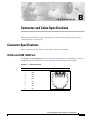
Connector Specifications B-1
10/100 and 10/100 /1000 Ports
100BASE-FX Ports B-2
Console Port B-2
B-1
B-1
Catalyst 3550 Multilayer Switch Hardware Installation Guide
iv
OL-6155-01
Contents
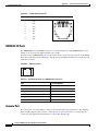
Cable and Adapter Specifications B-3
Two Twisted-Pair Cable Pinouts B-3
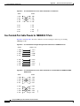
Four Twisted-Pair Cable Pinouts for 10/100 Ports B-3
Four Twisted-Pair Cable Pinouts for 1000BASE-T Ports B-4
Rollover Cable and Adapter Pinouts B-5
Identifying a Rollover Cable B-5
Adapter Pinouts B-5
APPENDIX
C
DC Power Connections
C-1
Connecting to DC Power C-1
Preparing for Installation C-1
Grounding the Switch C-2
Wiring the DC-Input Power Source
APPENDIX
D
C-4
Configuring the Switch with the CLI-Based Setup Program
Accessing the CLI Through Express Setup
D-1
D-1
Accessing the CLI Through the Console Port D-2
Connecting to the Console Port D-2
Starting the Terminal-Emulation Software D-3
Powering on the Switch D-4
Entering the Initial Configuration Information
IP Settings D-4
Completing the Setup Program D-5
D-4
INDEX
Catalyst 3550 Multilayer Switch Hardware Installation Guide
OL-6155-01
v
Contents
Catalyst 3550 Multilayer Switch Hardware Installation Guide
vi
OL-6155-01
Preface
Audience
This guide is for the networking or computer technician responsible for installing the Catalyst 3550
multilayer switches. We assume that you are familiar with the concepts and terminology of Ethernet and
local area networking.
Purpose
This guide documents the hardware features of the Catalyst 3550 family of multilayer switches. It
provides a quick setup procedure, describes the physical and performance characteristics of each switch,
explains how to install a switch, and includes basic troubleshooting information.
This guide does not describe system messages that you might receive or how to configure your switch
beyond the basic setup. For more information, see the Catalyst 3550 Multilayer Switch Software
Configuration Guide, the Catalyst 3550 Multilayer Switch Command Reference, the Catalyst 3550
Multilayer Switch System Message Guide, and the release notes on Cisco.com. For information about the
standard Cisco IOS Release 12.2 commands, see the Cisco IOS documentation set on Cisco.com.
Conventions
Command descriptions use these conventions:
•
Commands and keywords are in boldface text.
•
Arguments for which you supply values are in italic.
•
Square brackets ([ ]) mean optional elements.
•
Braces ({ }) group required choices, and vertical bars ( | ) separate the alternative elements.
•
Braces and vertical bars within square brackets ([{ | }]) mean a required choice within an optional
element.
Notes, cautions, and warnings use these conventions and symbols:
Note
Means reader take note. Notes contain helpful suggestions or references to materials not contained in
this manual.
Catalyst 3550 Multilayer Switch Hardware Installation Guide
OL-6155-01
vii
Preface
Conventions
Caution
Warning
Means reader be careful. In this situation, you might do something that could result in equipment
damage or loss of data.
IMPORTANT SAFETY INSTRUCTIONS
This warning symbol means danger. You are in a situation that could cause bodily injury. Before you
work on any equipment, be aware of the hazards involved with electrical circuitry and be familiar
with standard practices for preventing accidents. Use the statement number provided at the end of
each warning to locate its translation in the translated safety warnings that accompanied this
device. Statement 1071
SAVE THESE INSTRUCTIONS
Waarschuwing
BELANGRIJKE VEILIGHEIDSINSTRUCTIES
Dit waarschuwingssymbool betekent gevaar. U verkeert in een situatie die lichamelijk letsel kan
veroorzaken. Voordat u aan enige apparatuur gaat werken, dient u zich bewust te zijn van de bij
elektrische schakelingen betrokken risico's en dient u op de hoogte te zijn van de standaard
praktijken om ongelukken te voorkomen. Gebruik het nummer van de verklaring onderaan de
waarschuwing als u een vertaling van de waarschuwing die bij het apparaat wordt geleverd, wilt
raadplegen.
BEWAAR DEZE INSTRUCTIES
Varoitus
TÄRKEITÄ TURVALLISUUSOHJEITA
Tämä varoitusmerkki merkitsee vaaraa. Tilanne voi aiheuttaa ruumiillisia vammoja. Ennen kuin
käsittelet laitteistoa, huomioi sähköpiirien käsittelemiseen liittyvät riskit ja tutustu
onnettomuuksien yleisiin ehkäisytapoihin. Turvallisuusvaroitusten käännökset löytyvät laitteen
mukana toimitettujen käännettyjen turvallisuusvaroitusten joukosta varoitusten lopussa näkyvien
lausuntonumeroiden avulla.
SÄILYTÄ NÄMÄ OHJEET
Attention
IMPORTANTES INFORMATIONS DE SÉCURITÉ
Ce symbole d'avertissement indique un danger. Vous vous trouvez dans une situation pouvant
entraîner des blessures ou des dommages corporels. Avant de travailler sur un équipement, soyez
conscient des dangers liés aux circuits électriques et familiarisez-vous avec les procédures
couramment utilisées pour éviter les accidents. Pour prendre connaissance des traductions des
avertissements figurant dans les consignes de sécurité traduites qui accompagnent cet appareil,
référez-vous au numéro de l'instruction situé à la fin de chaque avertissement.
CONSERVEZ CES INFORMATIONS
Catalyst 3550 Multilayer Switch Hardware Installation Guide
viii
OL-6155-01
Preface
Conventions
Warnung
WICHTIGE SICHERHEITSHINWEISE
Dieses Warnsymbol bedeutet Gefahr. Sie befinden sich in einer Situation, die zu Verletzungen
führen kann. Machen Sie sich vor der Arbeit mit Geräten mit den Gefahren elektrischer Schaltungen
und den üblichen Verfahren zur Vorbeugung vor Unfällen vertraut. Suchen Sie mit der am Ende jeder
Warnung angegebenen Anweisungsnummer nach der jeweiligen Übersetzung in den übersetzten
Sicherheitshinweisen, die zusammen mit diesem Gerät ausgeliefert wurden.
BEWAHREN SIE DIESE HINWEISE GUT AUF.
Avvertenza
IMPORTANTI ISTRUZIONI SULLA SICUREZZA
Questo simbolo di avvertenza indica un pericolo. La situazione potrebbe causare infortuni alle
persone. Prima di intervenire su qualsiasi apparecchiatura, occorre essere al corrente dei pericoli
relativi ai circuiti elettrici e conoscere le procedure standard per la prevenzione di incidenti.
Utilizzare il numero di istruzione presente alla fine di ciascuna avvertenza per individuare le
traduzioni delle avvertenze riportate in questo documento.
CONSERVARE QUESTE ISTRUZIONI
Advarsel
VIKTIGE SIKKERHETSINSTRUKSJONER
Dette advarselssymbolet betyr fare. Du er i en situasjon som kan føre til skade på person. Før du
begynner å arbeide med noe av utstyret, må du være oppmerksom på farene forbundet med
elektriske kretser, og kjenne til standardprosedyrer for å forhindre ulykker. Bruk nummeret i slutten
av hver advarsel for å finne oversettelsen i de oversatte sikkerhetsadvarslene som fulgte med denne
enheten.
TA VARE PÅ DISSE INSTRUKSJONENE
Aviso
INSTRUÇÕES IMPORTANTES DE SEGURANÇA
Este símbolo de aviso significa perigo. Você está em uma situação que poderá ser causadora de
lesões corporais. Antes de iniciar a utilização de qualquer equipamento, tenha conhecimento dos
perigos envolvidos no manuseio de circuitos elétricos e familiarize-se com as práticas habituais de
prevenção de acidentes. Utilize o número da instrução fornecido ao final de cada aviso para
localizar sua tradução nos avisos de segurança traduzidos que acompanham este dispositivo.
GUARDE ESTAS INSTRUÇÕES
¡Advertencia!
INSTRUCCIONES IMPORTANTES DE SEGURIDAD
Este símbolo de aviso indica peligro. Existe riesgo para su integridad física. Antes de manipular
cualquier equipo, considere los riesgos de la corriente eléctrica y familiarícese con los
procedimientos estándar de prevención de accidentes. Al final de cada advertencia encontrará el
número que le ayudará a encontrar el texto traducido en el apartado de traducciones que acompaña
a este dispositivo.
GUARDE ESTAS INSTRUCCIONES
Catalyst 3550 Multilayer Switch Hardware Installation Guide
OL-6155-01
ix
Preface
Conventions
Varning!
VIKTIGA SÄKERHETSANVISNINGAR
Denna varningssignal signalerar fara. Du befinner dig i en situation som kan leda till personskada.
Innan du utför arbete på någon utrustning måste du vara medveten om farorna med elkretsar och
känna till vanliga förfaranden för att förebygga olyckor. Använd det nummer som finns i slutet av
varje varning för att hitta dess översättning i de översatta säkerhetsvarningar som medföljer denna
anordning.
SPARA DESSA ANVISNINGAR
Catalyst 3550 Multilayer Switch Hardware Installation Guide
x
OL-6155-01
Preface
Conventions
Aviso
INSTRUÇÕES IMPORTANTES DE SEGURANÇA
Este símbolo de aviso significa perigo. Você se encontra em uma situação em que há risco de lesões
corporais. Antes de trabalhar com qualquer equipamento, esteja ciente dos riscos que envolvem os
circuitos elétricos e familiarize-se com as práticas padrão de prevenção de acidentes. Use o
número da declaração fornecido ao final de cada aviso para localizar sua tradução nos avisos de
segurança traduzidos que acompanham o dispositivo.
GUARDE ESTAS INSTRUÇÕES
Advarsel
VIGTIGE SIKKERHEDSANVISNINGER
Dette advarselssymbol betyder fare. Du befinder dig i en situation med risiko for
legemesbeskadigelse. Før du begynder arbejde på udstyr, skal du være opmærksom på de
involverede risici, der er ved elektriske kredsløb, og du skal sætte dig ind i standardprocedurer til
undgåelse af ulykker. Brug erklæringsnummeret efter hver advarsel for at finde oversættelsen i de
oversatte advarsler, der fulgte med denne enhed.
GEM DISSE ANVISNINGER
Catalyst 3550 Multilayer Switch Hardware Installation Guide
OL-6155-01
xi
Preface
Conventions
Catalyst 3550 Multilayer Switch Hardware Installation Guide
xii
OL-6155-01
Preface
Related Publications
Related Publications
These documents provide complete information about the switch and are available from this URL:
http://www.cisco.com/univercd/cc/td/doc/product/lan/c3550/index.htm
You can order printed copies of documents with a DOC-xxxxxx= number from the Cisco.com sites and
from the telephone numbers listed in the “Ordering Documentation” section on page xv.
•
Note
Release Notes for the Catalyst 3550 Multilayer Switch (not orderable but available on Cisco.com)
Switch requirements and procedures for initial configurations and software upgrades tend to change and
therefore appear only in the release notes. Before installing, configuring, or upgrading the switch, see
the release notes on Cisco.com for the latest information.
For hardware information about the switch, see these documents:
•
Catalyst 3550 Switch Hardware Installation Guide (not orderable but available on Cisco.com)
•
Catalyst 3550 Switch Getting Started Guide (order number DOC-7816575=)
•
Regulatory Compliance and Safety Information for the Catalyst 3550 Switch
(order number DOC-7816655 =
For software information for the Catalyst 3550 switches, see these documents:
•
Catalyst 3550 Multilayer Switch Software Configuration Guide (order number DOC-7811194=)
•
Catalyst 3550 Multilayer Switch Command Reference (order number DOC-7811195=)
•
Catalyst 3550 Multilayer Switch System Message Guide (order number DOC-7811196=)
Catalyst 3550 Multilayer Switch Hardware Installation Guide
OL-6155-01
xiii
Preface
Obtaining Documentation
•
Device manager online help (available on the switch)
•
Getting Started with Cisco Network Assistant (not orderable but available on Cisco.com)
•
1000BASE-T Gigabit Interface Converter Installation Note (not orderable but is available on
Cisco.com)
•
Catalyst GigaStack Gigabit Interface Converter Hardware Installation Guide
(order number DOC-786460=)
•
Installation Notes for the CWDM Passive Optical System (not orderable but available on Cisco.com)
Obtaining Documentation
Cisco provides several ways to obtain documentation, technical assistance, and other technical
resources. These sections explain how to obtain technical information from Cisco Systems.
Cisco.com
You can access the most current Cisco documentation on the World Wide Web at this URL:
http://www.cisco.com/univercd/home/home.htm
You can access the Cisco website at this URL:
http://www.cisco.com
International Cisco websites can be accessed from this URL:
http://www.cisco.com/public/countries_languages.shtml
Documentation CD-ROM
Cisco documentation and additional literature are available in a Cisco Documentation CD-ROM
package, which may have shipped with your product. The Documentation CD-ROM is updated regularly
and may be more current than printed documentation. The CD-ROM package is available as a single unit
or through an annual or quarterly subscription.
Registered Cisco.com users can order a single Documentation CD-ROM (product number
DOC-CONDOCCD=) through the Cisco Ordering tool:
http://www.cisco.com/en/US/partner/ordering/ordering_place_order_ordering_tool_launch.html
All users can order annual or quarterly subscriptions through the online Subscription Store:
http://www.cisco.com/go/subscription
Catalyst 3550 Multilayer Switch Hardware Installation Guide
xiv
OL-6155-01
Preface
Obtaining Technical Assistance
Ordering Documentation
You can find instructions for ordering documentation at this URL:
http://www.cisco.com/univercd/cc/td/doc/es_inpck/pdi.htm
You can order Cisco documentation in these ways:
•
Registered Cisco.com users (Cisco direct customers) can order Cisco product documentation from
the Networking Products MarketPlace:
http://www.cisco.com/en/US/partner/ordering/index.shtml
•
Nonregistered Cisco.com users can order documentation through a local account representative by
calling Cisco Systems Corporate Headquarters (California, USA.) at 408 526-7208 or, elsewhere in
North America, by calling 800 553-NETS (6387).
Documentation Feedback
You can submit comments electronically on Cisco.com. On the Cisco Documentation home page, click
Feedback at the top of the page.
You can send your comments in e-mail to [email protected].
You can submit comments by using the response card (if present) behind the front cover of your
document or by writing to the following address:
Cisco Systems
Attn: Customer Document Ordering
170 West Tasman Drive
San Jose, CA 95134-9883
We appreciate your comments.
Obtaining Technical Assistance
For all customers, partners, resellers, and distributors who hold valid Cisco service contracts, the Cisco
Technical Assistance Center (TAC) provides 24-hour, award-winning technical support services, online
and over the phone. Cisco.com features the Cisco TAC website as an online starting point for technical
assistance.
Cisco TAC Website
The Cisco TAC website (http://www.cisco.com/tac) provides online documents and tools for
troubleshooting and resolving technical issues with Cisco products and technologies. The Cisco TAC
website is available 24 hours a day, 365 days a year.
Accessing all the tools on the Cisco TAC website requires a Cisco.com user ID and password. If you
have a valid service contract but do not have a login ID or password, register at this URL:
http://tools.cisco.com/RPF/register/register.do
Catalyst 3550 Multilayer Switch Hardware Installation Guide
OL-6155-01
xv
Preface
Obtaining Additional Publications and Information
Opening a TAC Case
The online TAC Case Open Tool (http://www.cisco.com/tac/caseopen) is the fastest way to open P3 and
P4 cases. (Your network is minimally impaired or you require product information). After you describe
your situation, the TAC Case Open Tool automatically recommends resources for an immediate solution.
If your issue is not resolved using these recommendations, your case will be assigned to a Cisco TAC
engineer.
For P1 or P2 cases (your production network is down or severely degraded) or if you do not have Internet
access, contact Cisco TAC by telephone. Cisco TAC engineers are assigned immediately to P1 and P2
cases to help keep your business operations running smoothly.
To open a case by telephone, use one of the following numbers:
Asia-Pacific: +61 2 8446 7411 (Australia: 1 800 805 227)
EMEA: +32 2 704 55 55
USA: 1 800 553-2447
For a complete listing of Cisco TAC contacts, go to this URL:
http://www.cisco.com/warp/public/687/Directory/DirTAC.shtml
TAC Case Priority Definitions
To ensure that all cases are reported in a standard format, Cisco has established case priority definitions.
Priority 1 (P1)—Your network is “down” or there is a critical impact to your business operations. You
and Cisco will commit all necessary resources around the clock to resolve the situation.
Priority 2 (P2)—Operation of an existing network is severely degraded, or significant aspects of your
business operation are negatively affected by inadequate performance of Cisco products. You and Cisco
will commit full-time resources during normal business hours to resolve the situation.
Priority 3 (P3)—Operational performance of your network is impaired, but most business operations
remain functional. You and Cisco will commit resources during normal business hours to restore service
to satisfactory levels.
Priority 4 (P4)—You require information or assistance with Cisco product capabilities, installation, or
configuration. There is little or no effect on your business operations.
Obtaining Additional Publications and Information
Information about Cisco products, technologies, and network solutions is available from various online
and printed sources.
•
The Cisco Product Catalog describes the networking products offered by Cisco Systems, as well as
ordering and customer support services. Access the Cisco Product Catalog at this URL:
http://www.cisco.com/en/US/products/products_catalog_links_launch.html
•
Cisco Press publishes a wide range of networking publications. Cisco suggests these titles for new
and experienced users: Internetworking Terms and Acronyms Dictionary, Internetworking
Technology Handbook, Internetworking Troubleshooting Guide, and the Internetworking Design
Guide. For current Cisco Press titles and other information, go to Cisco Press online at this URL:
http://www.ciscopress.com
Catalyst 3550 Multilayer Switch Hardware Installation Guide
xvi
OL-6155-01
Preface
Obtaining Additional Publications and Information
•
Packet magazine is the Cisco quarterly publication that provides the latest networking trends,
technology breakthroughs, and Cisco products and solutions to help industry professionals get the
most from their networking investment. Included are networking deployment and troubleshooting
tips, configuration examples, customer case studies, tutorials and training, certification information,
and links to numerous in-depth online resources. You can access Packet magazine at this URL:
http://www.cisco.com/go/packet
•
iQ Magazine is the Cisco bimonthly publication that delivers the latest information about Internet
business strategies for executives. You can access iQ Magazine at this URL:
http://www.cisco.com/go/iqmagazine
•
Internet Protocol Journal is a quarterly journal published by Cisco Systems for engineering
professionals involved in designing, developing, and operating public and private internets and
intranets. You can access the Internet Protocol Journal at this URL:
http://www.cisco.com/en/US/about/ac123/ac147/about_cisco_the_internet_protocol_journal.html
•
Training—Cisco offers world-class networking training. Current offerings in network training are
listed at this URL:
http://www.cisco.com/en/US/learning/index.html
Catalyst 3550 Multilayer Switch Hardware Installation Guide
OL-6155-01
xvii
Preface
Obtaining Additional Publications and Information
Catalyst 3550 Multilayer Switch Hardware Installation Guide
xviii
OL-6155-01
C H A P T E R
1
Product Overview
The Catalyst 3550 family of multilayer switches—also referred to as the switches—are stackable
Ethernet switches to which you can connect workstations, Cisco IP Phones, and other network devices
such as servers, routers, and other switches. These switches also can be deployed as backbone switches,
aggregating Gigabit Ethernet traffic from other network devices.
This chapter provides a functional overview of the Catalyst 3550 switch models. These topics are
included:
•
Features, page 1-1
•
Front-Panel Description, page 1-4
•
Rear-Panel Description, page 1-10
•
Management Options, page 1-11
Features
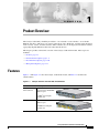
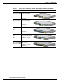
Figure 1-1 and Figure 1-2 show the Catalyst 3550 switch models, and Table 1-1 describes the
switch features.
Figure 1-1
Catalyst 3550-12T and 3550-12G Switch Models
Switch
WS-C3550-12T
Description
10 autosensing 10/100/1000
Ethernet ports
SYSTEM
RPS
MODE
STATUS
UTIL
DUPLX
SPEED
1
2
3
4
Catalyst
5
6
GBIC1-based
2
module slots
WS-C3550-12G
3550
7
Gigabit
8
9
10
1
2
2 autosensing 10/100/1000
Ethernet ports
SYSTEM
RPS
MODE
STATUS
UTIL
DUPLX
SPEED
1
3
Catalyst
2
5
4
3550
7
6
9
11
81594
10 GBIC-based Gigabit
module slots
12
8
10
1. GBIC = Gigabit Interface Converter
Catalyst 3550 Switch Hardware Installation Guide
OL-6155-01
1-1
Chapter 1
Product Overview
Features
Figure 1-2
Catalyst 3550-24, 3550-24-DC, 3550-FX, 3550-24PWR, and 3550-48 Switch Models
Switch
WS-C3550-24-SMI
WS-C3550-24-EMI
Description
24 autosensing 10/100
Ethernet ports
1
2
3
4
5
1X
SYSTEM
6
7
8
9
RPS
MODE
10
11
12
STATUS
1
15X
UTIL
DUPLX
SPEED
2
3
4
1X
5
6
7
8
9
2X
10
11
12
15X
16X
Catalyst
2X
2 GBIC-based Gigabit
module slots
WS-C3550-24-DCSMI
1
2
24 autosensing 10/100
Ethernet ports
1
2
3
4
5
1X
SYSTEM
6
7
8
9
RPS
MODE
10
11
12
STATUS
1
15X
UTIL
DUPLX
SPEED
2 GBIC-based Gigabit
module slots
DC-input power connector
WS-C3550-24-FXSMI
3550
16X
2
3
4
1X
5
6
7
8
9
2X
10
11
12
15X
16X
Catalyst
2X
1
3550
16X
2
24 100BASE-FX ports
2 GBIC-based Gigabit
module slots
SYSTEM
RPS
MODE
1X
2X
STATUS
3X
4X
UTIL
DUPLX
SPEED
5X
6X
7X
10BASE-
8X
T/100BAS
9X
E-TX
10X
11X
12X
13X
14X
15X
16X
17X
18X
Catalyst
19X
20X
21X
22X
23X
3550
24X
1
2
WS-C3550-48-SMI
WS-C3550-48-EMI
24 autosensing 10/100
inline-power Ethernet ports
1
2
3
4
1X
SYSTEM
5
6
7
8
9
RPS
MODE
10
11
12
STAT
UTIL
DUPLX
SPEED
1
15X
2
3
4
1X
5
6
7
8
9
2X
10
11
12
15X
2 GBIC-based Gigabit
module slots
Catalyst
3550
16X
2X
SERIES
INLINE
POWER
16X
1
2
48 autosensing 10/100
Ethernet ports
1
SYSTEM
1X
RPS
STATUS
UTIL
DUPLX
SPEED
MODE
2 GBIC-based Gigabit
module slots
2
3
4
5
6
7
8
9
10
11
12
13
14
15
16
17
15X 17X
2X
18
19
20
21
22
23
24
25
26
27
28
29
30
31
32
33
31X 33X
16X 18X
34
35
36
37
38
39
40
41
42
43
44
45
46
47
Catalyst
48
3550
47X
32X 34X
1
48X
2
81595
WS-C3550-24PWRSMI
WS-C3550-24PWREMI
Catalyst 3550 Switch Hardware Installation Guide
1-2
OL-6155-01
Chapter 1
Product Overview
Features
Table 1-1
Switch Features
Feature
Hardware
Description
•
2 or 10 Gigabit Ethernet 10BASE-T/100BASE-TX/1000BASE-T ports and 2 or
10 GBIC 1-based Gigabit Ethernet slots (Catalyst 3550-12T and 3550-12G
switches)
•
24 or 48 10BASE-T/100BASE-TX Ethernet ports and 2 GBIC-based Gigabit
Ethernet slots (Catalyst 3550-24, 3550-24DC, 3550-24PWR, and 3550-48
switches)
•
24 100BASE-FX ports (Catalyst 3550-24-FX switch)
•
Supports GBIC modules:
– 1000BASE-SX
– 1000BASE-LX/LX
– 1000BASE-ZX
– 1000BASE-T
– GigaStack
– CWDM
Configuration
Power
Redundancy
•
Supports Layer 3 routing (Catalyst 3550-12T and 3550-12G switches)
•
Supports optional Layer 3 routing (Catalyst 3550-24, 3550-24DC,
3550-24-FX, 3550-24PWR, and 3550-48 switches)
•
Autonegotiates speed and duplex operation on 10/100 or 10/100/1000 Ethernet
ports
•
Supports up to 12,000 MAC addresses (Catalyst 3550-12T and 3550-12G
switches)
•
Supports up to 8,000 MAC addresses (Catalyst 3550-24, 3550-24DC,
3550-24-FX, 3550-24PWR, and 3550-48 switches)
•
Checks for errors on a received packet, determines the destination port, stores
the packet in shared memory, and then forwards the packet to the destination
port
•
Connection for optional Cisco RPS 300 redundant power system or the Cisco
RPS 675 redundant power system that operates on AC input and supplies
backup DC power to the switch
Catalyst 3550 Switch Hardware Installation Guide
OL-6155-01
1-3
Chapter 1
Product Overview
Front-Panel Description
Table 1-1
Switch Features (continued)
Feature
Description
Inline Power
2
•
Power for Cisco IP Phones and access points from all 10/100 Ethernet ports
•
Auto-detection and control of inline power on a per-port basis on all 10/100
ports
•
Support for fan-fault and overtemperature detection through the Network
Assistant and the device manager.
1. Gigabit Interface Converter
2. Only Catalyst 3550-24PWR switch
Front-Panel Description
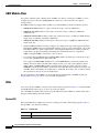
The switch front panel includes the 10/100 or 10/100/1000 Ethernet ports or 100BASE-FX ports, GBIC
module slots, and switch LEDs as shown in Figure 1-3 and described on the following pages.
Note
Figure 1-3 shows the Catalyst 3550-12T switch as an example. All the Catalyst switches have
similar components.
Figure 1-3
Switch Front Panel
3
Catalyst 3550 SERIES
SYSTEM
RPS
STATUS
UTIL
DUPLX
1
SPEED
1
2
3
4
5
6
7
8
9
10
MODE
1
2
4
5
1
Mode button
4
10/100 or 10/100/1000 Ethernet
ports or 100BASE-FX ports1
2
Switch LEDs
5
GBIC slots
3
Port LEDs
101603
2
1. Port numbering is from left to right, with port 1 on the far left. For ports grouped in pairs, the first
member of the pair (port 1) is above the second member (port 2). The GBIC slots are numbered
1 (left) and 2 (right) or 1 (above) and 2 (below).
Catalyst 3550 Switch Hardware Installation Guide
1-4
OL-6155-01
Chapter 1
Product Overview
Front-Panel Description
10/100 and 10/100/1000 Ports
The Fast Ethernet (10/100-Mbps) and Gigabit Ethernet (10/100/1000-Mbps) ports use standard RJ-45
connectors and Ethernet pinouts with internal crossovers. The maximum cable length is 328 feet (100
meters). 100BASE-TX and 1000BASE-T traffic requires twisted four-pair Category 5 cable. 10BASE-T
traffic can use Category 3 or Category 4 cable.
Fast Ethernet ports operate at 10 or 100 Mbps in either full- or half-duplex mode. In full-duplex mode,
two stations can send and receive traffic at the same time. Normally, 10-Mbps ports operate in
half-duplex mode, which means that stations can either receive or send traffic.
You can configure interface speed on Fast Ethernet and Gigabit Ethernet ports. On Fast Ethernet ports,
you can configure the duplex mode to full, half, or autonegotiate. On Gigabit Ethernet ports, you can
configure ports to full-duplex mode or to autonegotiate; half-duplex mode is not supported.
The default setting is autonegotiate. At this setting, the port senses the speed and duplex settings of the
attached device and advertises its own capabilities. If the connected device also supports
autonegotiation, the switch port negotiates the best connection (that is, the fastest line speed that both
devices support and full-duplex transmission if the attached device supports it) and configures itself
accordingly.
10/100 Inline Power Ports
The 10/100 ports on the Catalyst 3550-24PWR switch provide protocol support for Cisco IP Phones and
Cisco Aironet Access Points:
•
Provide –48 VDC power to all Cisco IP Phones and Cisco Aironet Access Points
•
Automatically detect a Cisco IP Phone or an access point that is connected
On a per-port basis, you can control whether or not a Catalyst 3550-24PWR 10/100 port automatically
provides power when an IP phone or an access point is connected. There are two inline power settings
for each 10/100 port: Auto and Never. When you select the Auto setting for inline power on a port, the
port only provides power if an IP phone or an access point is connected to it. The Auto setting is the
default. However, when you select the Never setting for inline power on a port, the port does not provide
power even if a Cisco IP phone or an access point is connected to it.
100BASE-FX Ports
The 100BASE-FX ports use 50/125- or 62.5/125-micron multimode fiber-optic cabling. In full-duplex
mode, the cable length from a switch to an attached device cannot exceed 6,562 feet (2 kilometers).
The 100BASE-FX ports operate only at 100 Mbps in either full- or half-duplex mode and do not support
autonegotiation. The half-duplex mode is the default setting.
You can connect a 100BASE-FX port to an SC or ST port on a target device by using one of the MT-RJ
fiber-optic patch cables listed in Table B-1 on page B-2.
Catalyst 3550 Switch Hardware Installation Guide
OL-6155-01
1-5
Chapter 1
Product Overview
Front-Panel Description
GBIC Module Slots
You cannot configure speed or duplex mode on GBIC slots, but for certain types of GBICs, you can
configure speed to not negotiate (nonegotiate) if connected to a device that does not support
autonegotiation.
The GBIC module slots support these modules to provide flexibility in media and distance options:
•
1000BASE-T GBIC module for copper connections of up to 328 feet (100 meters).
•
1000BASE-SX GBIC module for fiber-optic connections of up to 1,804 feet (550 meters)
multimode only.
•
1000BASE-LX/LH GBIC module for fiber-optic connections of up to 32,810 feet (10 kilometers)
single mode or 1,804 feet (550 meters) multimode.
•
1000BASE-ZX GBIC module for fiber-optic connections of up to 328,000 feet (100 kilometers)
single mode only.
•
GigaStack GBIC module for creating a 1-Gbps stack configuration of up to nine supported switches.
The GigaStack GBIC supports one full-duplex link (in a point-to-point configuration) or up to nine
half-duplex links (in a stack configuration) to other Gigabit Ethernet devices. When you use the
required Cisco proprietary signaling and cabling, the maximum distance for a GigaStack
GBIC-to-GigaStack GBIC connection is 3 feet (1 meter).
•
Coarse Wave Division Multiplexing (CWDM) GBIC modules for fiber-optic connections of up to
393,719 feet (120 kilometers) single mode only.
Cisco-approved CWDM GBIC modules have a serial EEPROM that contains the module serial
number, the vendor name and vendor ID, a unique security code, and cyclic redundancy check
(CRC). When a CWDM GBIC module is inserted in the switch, the switch software reads the
EEPROM to check the serial number, vendor name and vendor ID, and recompute the security code
and CRC. If the serial number, the vendor name or vendor ID, the security code, or CRC is invalid,
the switch places the port in an error-disabled state.
For more information about GBICs, see the documentation included with your GBIC module and
Related Publications, page xiii, for a list of related documentation.
LEDs
You can use the switch LEDs to monitor switch activity and its performance. Figure 1-3 shows the LEDs
and the Mode button that you use to select one of the port modes.
All of the LEDs described in this section except the utilization meter (UTIL) are visible on the device
manager and through the Network Assistant.
System LED
The system LED shows whether the system is receiving power and is functioning properly. Table 1-2
lists the LED colors and their meanings.
Table 1-2
System LED
Color
System Status
Off
System is not powered on.
Catalyst 3550 Switch Hardware Installation Guide
1-6
OL-6155-01
Chapter 1
Product Overview
Front-Panel Description
Table 1-2
System LED (continued)
Color
System Status
Green
System is operating normally.
Amber
System is receiving power but is not functioning properly.
RPS LED
The RPS LED shows the RPS status. Table 1-3 lists the LED colors and their meanings.
Table 1-3
RPS LED
Color
RPS Status
Off
RPS is off or not properly connected.
Solid green
RPS is connected and ready to provide back-up power, if required.
Blinking green
RPS is connected but is unavailable because it is providing power to another device
(redundancy has been allocated to a neighboring device).
Solid amber
The RPS is in standby mode or in a fault condition. Press the Standby/Active button
on the RPS, and the LED should turn green. If it does not, the RPS fan could have
failed. Contact Cisco Systems.
Blinking amber
The internal power supply in a switch has failed, and the RPS is providing power
to the switch (redundancy has been allocated to this device).
For more information about the Cisco RPS 300 or the Cisco RPS 675, see the documentation included
with the RPS.
Port LEDs and Modes
Each RJ-45 port and GBIC module slot has a port LED. These port LEDs, as a group or individually,
display information about the switch and about the individual ports. The port mode determines the type
of information displayed through the port LEDs. Table 1-4 lists the mode LEDs and their associated port
modes and meanings.
To select or change a mode, press the Mode button (or Mode label on the Catalyst 3550-48 switch) until
the desired mode is highlighted. When you change port modes, the meanings of the port LED colors also
change. Table 1-5 explains how to interpret the port LED colors in different port modes.
You can also use the Mode button to activate the Express Setup program or to clear the switch IP address
and all switch settings. See the “Clearing the Switch IP Address and Configuration” section on page 3-1
for more information.
Table 1-4
Port Mode LEDs
Mode LED
Port Mode
Description
STATUS
Port status
The port status. This is the default mode.
Switch utilization
The current bandwidth in use by the switch. (See Figure 1-4
through Figure 1-8.)
Port duplex mode
The port duplex mode: full duplex or half duplex.
UTIL
1
DUPLX
Catalyst 3550 Switch Hardware Installation Guide
OL-6155-01
1-7
Chapter 1
Product Overview
Front-Panel Description
Table 1-4
Port Mode LEDs (continued)
Mode LED
SPEED
LINE PWR
2
Port Mode
Description
Port speed
The port operating speed: 10, 100, or 1000 Mbps.
Port inline power
The inline power status: on or off.
1. Not available on Catalyst 3550-24PWR switches
2. Available only on Catalyst 3550-24PWR switches
Table 1-5
Meaning of LED Colors in Different Modes
Port Mode
LED Color
Meaning
STATUS
(port status)
Off
No link, or port was administratively shut down.
Solid green
Link present.
Blinking green Activity. Port is sending or receiving data.
Alternating
green-amber
Link fault. Error frames can affect connectivity, and errors such as
excessive collisions, CRC errors, and alignment and jabber errors
are monitored for a link-fault indication.
Solid amber
Port is blocked by Spanning Tree Protocol (STP) and is not
forwarding data.
Note
After a port is reconfigured, the port LED can remain amber
for up to 30 seconds as STP checks the switch for possible
loops.
Blinking amber Port is blocked by STP and is sending or receiving packets.
1
Green
Port LEDs display backplane utilization on a logarithmic scale. (See
Figure 1-4 through Figure 1-8.)
Amber
Peak total backplane utilization over the last 24 hours.
DUPLX
(duplex)
Off
Port is operating in half duplex.
Green
Port is operating in full duplex.
SPEED
10/100 and 10/100/1000 ports
UTIL
(utilization)
Off
Port is operating at 10 Mbps.
Green
Port is operating at 100 Mbps.
Blinking green Port is operating at 1000 Mbps.
GBIC ports
Off
Port is not operating.
Blinking green Port is operating at 1000 Mbps.
LINE PWR2
Off
Inline power is off.
Green
Inline power is on.
If the Cisco IP Phone is receiving power from an AC power source,
the port LED is off even if the IP phone is connected to the switch
port. The LED turns green only when the switch port is providing
power.
1. Not available on Catalyst 3550-24PWR switches
2. Available only on Catalyst 3550-24PWR switches
Catalyst 3550 Switch Hardware Installation Guide
1-8
OL-6155-01
Chapter 1
Product Overview
Front-Panel Description
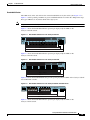
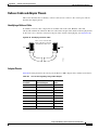
Bandwidth Utilization
The UTIL mode on the switch shows the current bandwidth in use by the switch. (See Figure 1-4 to
Figure 1-8.) If all possible port LEDs are green, bandwidth utilization is in the 50 to 100 percent range.
Every port LED that is off (black) divides this range by two.
Note
The port LEDs on the Catalyst 3550-24PWR switch do not show bandwidth utilization.
Figure 1-4 shows the bandwidth utilization percentages displayed by the LEDs on the
Catalyst 3550-12T switch.
Figure 1-4
Bandwidth Utilization for the Catalyst 3550-12T
Catalyst 3550 SERIES
SYSTEM
RPS
STATUS
UTIL
DUPLX
1
2
1
3
4
5
6
7
8
9
10
2
74026
SPEED
MODE
< 25% +
25% – 49% +
50% +
Figure 1-5 shows the bandwidth utilization percentages displayed by the LEDs on the
Catalyst 3550-12G switch.
Figure 1-5
Bandwidth Utilization for the Catalyst 3550-12G
Catalyst 3550 SERIES
SYSTEM
RPS
STATUS
UTIL
DUPLX
SPEED
1
1
1
1
1
2
2
2
2
2
9
10
74039
MODE
< 25% +
25% – 49% +
50% +
Figure 1-6 shows the bandwidth utilization percentages displayed by the LEDs on the Catalyst 3550-24
and 3550-24-DC switches.
Bandwidth Utilization for the Catalyst 3550-24 and 3550-24-DC
1
1X
2
3
4
5
6
7
8
9
10
11 12
13 14
11X
15 16
17 18
19 20
13X
21 22
Catalyst 3550 SERIES
23 24
15X
1
SYSTEM
RPS
MODE
STATUS
UTIL
2X
12X
14X
DUPLX
SPEED
16X
2
74023
Figure 1-6
< 25% +
25% – 49% +
50% +
Figure 1-7 shows the bandwidth utilization percentages displayed by the LEDs on the
Catalyst 3550-48 switch.
Catalyst 3550 Switch Hardware Installation Guide
OL-6155-01
1-9
Chapter 1
Product Overview
Rear-Panel Description
Figure 1-7
Bandwidth Utilization for the Catalyst 3550-48
Catalyst 3550 SERIES
1
2
3
24
5
6
7
8
9
10
11 12
13 14
15 16
17 18
19 20
21 22
23 24
25 26
27 28
29 31
31 32
33 34
35 36
37 38
39 40
41 42
43 44
45 46
47 48
1X
15X
17X
31X
33X
47X
2X
16X
18X
32X
34X
48X
RPS
STATUS
UTIL
2
DUPLX
SPEED
MODE
74024
1
SYSTEM
< 25% +
25% – 49% +
50% +
Figure 1-8 shows the bandwidth utilization percentages displayed by the LEDs on the
Catalyst 3550-24-FX switch.
Figure 1-8
Bandwidth Utilization for the Catalyst 3550-24-FX
Catalyst 3550 SERIES
RPS
STATUS
UTIL
2
DUPLX
SPEED
MODE
74099
1
SYSTEM
< 25% +
25% – 49% +
50% +
Rear-Panel Description
Other than the Catalyst 3550-24-DC switch, the switch rear panels have an AC power connector, an RPS
connector, and an RJ-45 console port, which are shown in Figure 1-9 and described in this section.
The rear panel of the 3550-24-DC switch has a DC power connector (also referred to as the terminal
block header), an RJ-45 console port, and a ground lug. The switch is shipped with a terminal block plug
in the DC power connector.
Note
Figure 1-9 shows the Catalyst 3550-12T switch as an example. All the Catalyst switches have similar
components.
Figure 1-9
Switch Rear Panel
DC OUTPUT 1
100-240V~
5-3A
50/60Hz
1
2
3
1
RPS connector
3
Console port
2
AC power connector
4
Fan exhaust
4
101604
CONSOLE
Catalyst 3550 Switch Hardware Installation Guide
1-10
OL-6155-01
Chapter 1
Product Overview
Management Options
AC Power Connector
For AC-powered switches, the internal power supply is an autoranging unit that supports input voltages
between 100 and 240 VAC.
For the Catalyst 2440-24-DC power information, see Appendix C, “DC Power Connections.”
Cisco RPS Connector
For protection against a power supply failure, you can connect a Cisco RPS to the switch. The Cisco RPS
can support six external network devices and provide power to one failed device at a time. It
automatically senses when the internal power supply of a connected device fails and provides power to
the failed device, preventing loss of network traffic.
The Cisco RPS 300 has two output levels: –48 V and 12 V with a total maximum output power of 300 W.
The Cisco RPS 675 has two output levels: –48 V and 12 V with a total maximum output power of 675 W.
These Cisco RPS models support the Catalyst 3550 switches:
•
Cisco RPS 300 (model PWR300-AC-RPS-N1) supports the
Catalyst 3550-12T, 3550-12G, 3550-24, 3550-FX, and 3550-48 switches.
•
Cisco RPS 675 (model PWR675-AC-RPS-N1) supports the
Catalyst 3550-12T, 3550-12G, 3550-24, 3550-FX, 3550-24PWR, and 3550-48 switches.
The Cisco RPS 300 does not support the Catalyst 3550-24-DC or 3550-24PWR switch. The Cisco RPS
675 does not support the Catalyst 3550-24-DC switch.
The RPS 300 and RPS 675 models also support other Cisco devices. See the RPS documentation for
more information.
Console Port
You can connect the switch to a PC by using the console port and the supplied RJ-45-to-DB-9 adapter
cable. If you want to connect the switch console port to a terminal, you need to provide an
RJ-45-to-DB-25 female DTE adapter. You can order a kit (part number ACS-DSBUASYN=) containing
that adapter from Cisco.
Management Options
The Catalyst 3550 switches offer several management options:
•
Network Assistant
•
The Network Assistant is a GUI-based application that you can install and run on your desktop; you
do not need a web browser to run it. You can use Network Assistant to manage and monitor switch
clusters or standalone devices. For more information, see the Getting Started with Cisco Network
Assistant guide and the Network Assistant online help.
Catalyst 3550 Switch Hardware Installation Guide
OL-6155-01
1-11
Chapter 1
Product Overview
Management Options
•
Device manager
You can use the device manager, which is in the switch memory, to manage individual and
standalone switches. The device manager is accessible after you have run the Express Setup program
(see the getting started guide for more information about running Express Setup). Use the device
manager to perform basic switch configuration and monitoring. You can access the device manager
from anywhere in your network through a web browser.
To launch the device manager, enter the switch IP address in the web browser, and press Enter.
The device manager page appears.
See the device manager online help for more information.
•
Cisco IOS command-line interface (CLI)
The switch CLI is based on Cisco IOS software and is enhanced to support desktop-switching
features. You can fully configure and monitor the switch and switch cluster members from the CLI.
You can access the CLI either by connecting your management station directly to the switch console
port or by using Telnet from a remote management station. See the command reference on
Cisco.com for more information.
•
SmartPort Macros
SmartPort macros provide a convenient way to save and share common switch configurations. You
can use SmartPort macros to enable features and settings based on the location of a switch in the
network and for mass configuration deployments across the network.
Cisco provides a collection of pretested, Cisco-recommended baseline SmartPort macros for
Catalyst switches. You can use the macros to build and deploy Cisco-recommended network designs
and configurations. For more information about SmartPort macros, see the software configuration
guide and the SmartPort information available on Cisco.com.
•
CiscoView application
The CiscoView device-management application displays the switch image that you can use to set
configuration parameters and to view switch status and performance information. The CiscoView
application, which you purchase separately, can be a standalone application or part of an SNMP
platform. See the CiscoView documentation for more information.
•
SNMP network management
You can manage switches from a SNMP-compatible management station that is running platforms
such as HP OpenView or SunNet Manager. The switch supports a comprehensive set of MIB
extensions and four Remote Monitoring (RMON) groups. See the software configuration guide on
Cisco.com and the documentation that came with your SNMP application for more information.
•
Cisco Intelligence Engine 2100 (IE2100)
Cisco IE200 Series Configuration Registrar is a network management device that works with
embedded Cisco Networking Services (CNS) agents in the switch software. You can automate initial
configurations and configuration updates by generating switch-specific configuration changes,
sending them to the switch, executing the configuration change, and logging the results.
Network Configurations
See the software configuration guide on Cisco.com for network configuration concepts and examples.
Catalyst 3550 Switch Hardware Installation Guide
1-12
OL-6155-01
C H A P T E R
2
Switch Installation
This chapter describes how to prepare for installation, how to install the switch, and how to make
connections to it. Read the topics and perform the procedures in the order that they are presented:
•
Preparing for Installation, page 2-1
•
Installing the Switch, page 2-5
•
Installing the Optional Ground Kit, page 2-15
•
Powering the Switch and Connecting Devices, page 2-16
Preparing for Installation
This section covers these topics:
•
Warnings, page 2-1
•
Site Requirements, page 2-4
•
Verifying Package Contents, page 2-4
Warnings
These warnings are translated into several languages in the Regulatory Compliance and Safety
Information for the Catalyst 3550 Switch.
Warning
Only trained and qualified personnel should be allowed to install, replace, or service this equipment.
Statement 1030
Warning
Read the installation instructions before connecting the system to the power source. Statement 1004
Warning
For connections outside the building where the equipment is installed, the following ports must be
connected through an approved network termination unit with integral circuit protection:
10/100 Ethernet. Statement 1044
Catalyst 3550 Switch Hardware Installation Guide
OL-6155-01
2-1
Chapter 2
Switch Installation
Preparing for Installation
Warning
Installation of the equipment must comply with local and national electrical codes. Statement 1074
Warning
Before working on equipment that is connected to power lines, remove jewelry (including rings,
necklaces, and watches). Metal objects will heat up when connected to power and ground and can
cause serious burns or weld the metal object to the terminals. Statement 43
Warning
Do not stack the chassis on any other equipment. If the chassis falls, it can cause severe bodily injury
and equipment damage. Statement 48
Warning
The plug-socket combination must be accessible at all times because it serves as the main
disconnecting device. Statement 66
Warning
This equipment is intended to be grounded. Ensure that the host is connected to earth ground during
normal use. Statement 39
Warning
To prevent the switch from overheating, do not operate it in an area that exceeds the maximum
recommended ambient temperature of 113°F (45°C). To prevent airflow restriction, allow at least
3 inches (7.6 cm) of clearance around the ventilation openings. Statement 17B
Warning
When installing or replacing the unit, the ground connection must always be made first and
disconnected last. Statement 1046
Warning
Do not work on the system or connect or disconnect cables during periods of lightning activity.
Statement 1001
Warning
Ultimate disposal of this product should be handled according to all national laws and regulations.
Statement 1040
Warning
If a redundant power system (RPS) is not connected to the switch, install an RPS connector cover on
the back of the switch. Statement 265
Warning
To comply with safety regulations, mount switches on a wall with the front panel facing up.
Statement 266
Catalyst 3550 Switch Hardware Installation Guide
2-2
OL-6155-01
Chapter 2
Switch Installation
Preparing for Installation
Warning
The Catalyst 3550-24-DC contains no field-replaceable units (FRUs). Do not open the chassis or
attempt to remove or replace any components. For information about obtaining service for this unit,
contact your reseller or Cisco sales representative. Statement 121B
Warning
This unit is intended for installation in restricted access areas. A restricted access area can be
accessed only through the use of a special tool, lock and key, or other means of security.
Statement 1017
Warning
Ethernet cables must be shielded when used in a central office environment. Statement 171
Warning
Before performing any of the following procedures, ensure that power is removed from the DC circuit.
Statement 1003
Warning
Class 1 laser product. Statement 1008
Warning
An exposed wire lead from a DC-input power source can conduct harmful levels of electricity. Be sure
that no exposed portion of the DC-input power source wire extends from the terminal block plug.
Statement 122
Warning
Voltages that present a shock hazard can exist on inline power circuits if interconnections are made
by using uninsulated exposed metal contacts, conductors, or terminals. Avoid using such
interconnection methods unless the exposed metal parts are in a restricted access location and users
and service people who are authorized to access the location are made aware of the hazard. A
restricted access area can be accessed only through the use of a special tool, lock and key, or other
means of security. Statement 1072
Warning
Attach only the Cisco RPS (model PWR300-AC-RPS-N1) to the RPS receptacle. Statement 100B
Warning
Attach only the Cisco RPS (model PWR675-AC-RPS-N1) to the RPS receptacle. Statement 100C
Catalyst 3550 Switch Hardware Installation Guide
OL-6155-01
2-3
Chapter 2
Switch Installation
Preparing for Installation
Site Requirements
When determining where to place the switch, be sure to observe these requirements:
•
Operating environment is within the ranges listed in Appendix A, “Technical Specifications.”
•
Clearance to front and rear panels is such that
– Front-panel indicators can be easily read.
– Access to ports is sufficient for unrestricted cabling.
– Rear-panel power connector is within reach of an AC power receptacle.
Note
•
Airflow around the switch and through the vents is unrestricted.
•
Temperature around the unit does not exceed 113° F (45° C).
If the switch is installed in a closed or multirack assembly, the temperature around it might be greater
than normal room temperature.
•
Cabling is away from sources of electrical noise, such as radios, power lines, and fluorescent
lighting fixtures. Make sure that the cabling is safely away from other devices that might damage
the cables.
•
For sites requiring compliance to Telcordia GR-1089-CORE Intra-building Lightning requirements,
all 10/100 and 10/100/1000 ports must be connected with shielded cable grounded at both ends.
Verifying Package Contents
Note
Carefully remove the contents from the shipping container, and check each item for damage. If any item
is missing or damaged, contact your Cisco representative or reseller for support. Return all packing
material to the shipping container, and save it.
The switch is shipped with these items:
•
This Catalyst 3550 Series Hardware Installation Guide
•
Where to Find the Catalyst 3550 Documentation flyer
•
Product registration card
•
AC power cord (AC-powered switches)
•
One RJ-45-to-DB-9 adapter cable
•
Mounting kit containing:
– Four rubber feet for mounting the switch on a table
– Two 19-inch rack-mounting brackets
– Four Phillips flat-head screws for attaching the brackets to the switch (Catalyst 3550-12T
and 3550-12G switches)
– Six Phillips flat-head screws for attaching the brackets to the switch (Catalyst 3550-24,
3550-24-DC, 3550-24-FX, 3550-24PWR, and 3550-48 switches)
– Four Phillips machine screws for attaching the brackets to a rack
Catalyst 3550 Switch Hardware Installation Guide
2-4
OL-6155-01
Chapter 2
Switch Installation
Installing the Switch
– One cable guide and one black Phillips machine screw for attaching the cable guide to one of
the mounting brackets
– One RPS connector cover (for wall mounting)
– Two Phillips pan-head screws (for attaching the RPS cover)
– Four Phillips truss-head screws (for wall-mounting brackets)
– One DC terminal block plug (also called a terminal block header; only Catalyst 3550-24-DC
switches)
Installing the Switch
This section describes these installation procedures:
•
Rack-Mounting, page 2-5
•
Wall Mounting, page 2-12
•
Table or Shelf Mounting, page 2-14
Rack-Mounting
Warning
To prevent bodily injury when mounting or servicing this unit in a rack, you must take special
precautions to ensure that the system remains stable. The following guidelines are provided to ensure
your safety:
•
This unit should be mounted at the bottom of the rack if it is the only unit in the rack.
•
When mounting this unit in a partially filled rack, load the rack from the bottom to the
top with the heaviest component at the bottom of the rack.
•
If the rack is provided with stabilizing devices, install the stabilizers before mounting
or servicing the unit in the rack. Statement 1006
To install the switch in a 19-inch or 24-inch rack (24-inch racks require optional mounting hardware),
follow the instructions described in these procedures:
Note
•
Attaching Brackets to the Catalyst 3550-12T and 3550-12G Switches, page 2-6
•
Attaching Brackets to the Catalyst 3550-24, 3550-24-DC, 3550-24-FX, 3550-24PWR, and
3550-48 Switches, page 2-8
•
Mounting the Switch in a Rack, page 2-12
Installing the switch in a 24-inch rack requires an optional bracket kit not included with the switch. You
can order a kit containing the 24-inch rack-mounting brackets and hardware from Cisco. For the
Catalyst 3550-12T and 3550-12G switches, order part number RCKMNT-3550-1.5RU=. For the
Catalyst 3550-24, 3550-24-DC, 3550-24-FX, 3550-24PWR, and 3550-48 switches, order part number
RCKMNT-1RU=.
Catalyst 3550 Switch Hardware Installation Guide
OL-6155-01
2-5
Chapter 2
Switch Installation
Installing the Switch
Attaching Brackets to the Catalyst 3550-12T and 3550-12G Switches
The bracket orientation and the brackets that you use depend on whether you are attaching the brackets
for a 19-inch or a 24-inch rack. For 19-inch racks, use bracket part number 700-11523-01; for 24-inch
racks, use bracket part number 700-12398-01. Figure 2-1 through Figure 2-6 show how to attach each
type bracket to one side of the switch. Follow the same steps to attach the second bracket to the opposite
side.
Figure 2-1
Attaching Brackets for 19-Inch Racks, Front Panel Forward
SYSTEM
RPS
MODE
STATUS
UTIL
DUPLX
SPEED
1
2
3
4
5
19" Configuration
Figure 2-2
51364
Phillips
flat-head
screws
Attaching Brackets for 24-Inch Racks, Front Panel Forward
Phillips
flat-head
screws
SYSTEM
RPS
MODE
STATUS
UTIL
DUPLX
SPEED
1
3
4
24" Configuration
60912
2
Catalyst 3550 Switch Hardware Installation Guide
2-6
OL-6155-01
Chapter 2
Switch Installation
Installing the Switch
Figure 2-3
Attaching Brackets for 19-Inch Racks, Rear Panel Forward
Phillips
flat-head
screws
Figure 2-4
51365
19" Configuration
Attaching Brackets for 24-Inch Racks, Rear Panel Forward
Phillips
flat-head
screws
60914
24" Configuration
Catalyst 3550 Switch Hardware Installation Guide
OL-6155-01
2-7
Chapter 2
Switch Installation
Installing the Switch
Figure 2-5
Attaching Brackets for 19-Inch Telco Racks
2
3
Catalyst
4
5
6
3550 SER
IES
7
8
9
10
11
12
Phillips
flat-head
screws
Figure 2-6
74035
19" Configuration
Attaching Brackets for 24-Inch Telco Racks
2
3
4
Catalyst
5
6
3550 SER
IES
7
8
9
10
11
12
Phillips
flat-head
screws
74040
24" Configuration
Attaching Brackets to the Catalyst 3550-24, 3550-24-DC, 3550-24-FX, 3550-24PWR, and
3550-48 Switches
The bracket orientation and the brackets that you use depend on whether you are attaching the brackets
for a 19-inch or a 24-inch rack. For 19-inch racks, use bracket part number 700-8209-01; for 24-inch
racks, use bracket part number 700-13248-01. Figure 2-7 through Figure 2-12 show how to attach each
type bracket to one side of the switch. Follow the same steps to attach the second bracket to the opposite
side.
Note
Before you attach the brackets on the Catalyst 3550-24-FX switch, remove the screws that are on the
bottom-front of the chassis. Attach the bracket by using the supplied Phillips flat-head screws, as shown
in Figure 2-7.
Catalyst 3550 Switch Hardware Installation Guide
2-8
OL-6155-01
Chapter 2
Switch Installation
Installing the Switch
Figure 2-7
Attaching Brackets for 19-Inch Racks, Front Panel Forward
1
SYSTEM
2
3
1X
4
5
6
7
8
9
RPS
MODE
10
11
12
STATUS
UTIL
DUPLX
SPEED
11X
2X
60138
12X
19" Configuration
Phillips
flat-head
screws
Attaching Brackets for 24-Inch Racks, Front Panel Forward
1
SYSTEM
1X
2
3
4
5
RPS
MODE
Phillips
flat-head
screws
STATUS
UTIL
DUPLX
SPEED
6
7
8
9
10
11
12
11X
2X
12X
24" Configuration
60139
Figure 2-8
Catalyst 3550 Switch Hardware Installation Guide
OL-6155-01
2-9
Chapter 2
Switch Installation
Installing the Switch
Figure 2-9
Attaching Brackets for 19-Inch Racks, Rear Panel Forward
CONSO
LE
Phillips
flat-head
screws
49809
19" Configuration
Figure 2-10 Attaching Brackets for 24-Inch Racks, Rear Panel Forward
CONSO
LE
Phillips
flat-head
screws
49810
24" Configuration
Catalyst 3550 Switch Hardware Installation Guide
2-10
OL-6155-01
Chapter 2
Switch Installation
Installing the Switch
Figure 2-11 Attaching Brackets for 19-Inch Telco Racks
1
Catalyst
3550 SE
RIES
2
Phillips
flat-head
screws
74036
19" Configuration
Figure 2-12 Attaching Brackets for 24-Inch Telco Racks
1
Catalyst
3550 SE
RIES
2
Phillips
flat-head
screws
74037
24" Configuration
Catalyst 3550 Switch Hardware Installation Guide
OL-6155-01
2-11
Chapter 2
Switch Installation
Installing the Switch
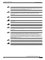
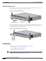
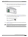
Mounting the Switch in a Rack
After the brackets are attached to the switch, use the four supplied number-12 Phillips machine screws
to securely attach the brackets to the rack, as shown in Figure 2-13.
Figure 2-13 Mounting the Switch in a Rack
SYSTEM
RPS
MODE
STATUS
UTIL
DUPLX
SPEED
1
2
3
4
Catalyst
5
6
3550 SER
IES
7
8
9
74033
10
1
2
Phillips machine screws
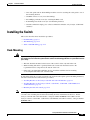
We recommend attaching the cable guide to prevent the cables from obscuring the front panel of the
switch and the other devices installed in the rack. Use the supplied black screw, as shown in Figure 2-14,
to attach the cable guide to the left or right bracket.
Figure 2-14 Attaching the Cable Guide on the Switch
SYSTEM
RPS
MODE
STATUS
UTIL
DUPLX
SPEED
1
2
3
4
Catalyst
5
6
3550 SER
IES
7
8
9
1
2
74034
10
Cable guide screw
Wall Mounting
To install the switch on a wall, follow the instructions in these procedures:
Note
•
Attaching the Brackets to the Switch, page 2-13
•
Attaching the RPS Connector Cover, page 2-13
•
Mounting the Switch on a Wall, page 2-14
The illustrations in this section show the Catalyst 3550-12T switch as an example. All the Catalyst 3550
switches are wall-mounted following the same procedures.
Catalyst 3550 Switch Hardware Installation Guide
2-12
OL-6155-01
Chapter 2
Switch Installation
Installing the Switch
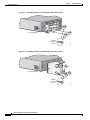
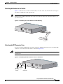
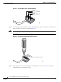
Attaching the Brackets to the Switch
Figure 2-15 shows how to attach a 19-inch bracket to one side of the switch. Follow the same steps to
attach the second bracket to the opposite side.
Note
On the Catalyst 3550-24-FX switch, remove the screws that are in the side of the chassis before you
attach the brackets.
Figure 2-15 Attaching the 19-Inch Brackets for Wall Mounting
100-240V
5-3A
50/60Hz
~
CONSOL
Phillips
truss-head
screws
51368
E
Attaching the RPS Connector Cover
If you are not using an RPS with your switch, use the two Phillips pan-head screws to attach the RPS
connector cover to the back of the switch, as shown in Figure 2-16.
Warning
If an RPS is not connected to the switch, install an RPS connector cover on the back of the switch.
Statement 265
Figure 2-16 Attaching the RPS Connector Cover on the Switch
1
100-240V
5-3A
50/60Hz
RPS
connector
Phillips
pan-head cover
screws
~
86483
DC OUT
PUT
CONSOL
E
RPS
connector
Catalyst 3550 Switch Hardware Installation Guide
OL-6155-01
2-13
Chapter 2
Switch Installation
Installing the Switch
Mounting the Switch on a Wall
For the best support of the switch and cables, make sure that the switch is attached securely to wall studs
or to a firmly attached plywood mounting backboard. Mount the switch with the front panel facing up,
as shown in Figure 2-17.
Warning
To comply with safety regulations, mount the switches on a wall with the front panel facing up.
Statement 266
Figure 2-17 Mounting the Switch on a Wall
12
11
10
Catalys
t 3550
9
8
7
6
5
4
3
2
1
MODE
SYSTEM
STATUS RPS
DUPLX UTIL
SPEED
60967
User-supplied
screws
User-supplied
screws
Table or Shelf Mounting
Follow these steps to install the switch on a table or shelf:
Step 1
Locate the adhesive strip with the rubber feet in the mounting-kit envelope. Attach the four rubber feet
to the recessed areas on the bottom of the unit.
Step 2
Place the switch on the table or shelf near an AC power source.
Catalyst 3550 Switch Hardware Installation Guide
2-14
OL-6155-01
Chapter 2
Switch Installation
Installing the Optional Ground Kit
Installing the Optional Ground Kit
For switches that require a two-hole lug for grounding, you can order a kit containing the ground lug and
hardware from Cisco. For the Catalyst 3550-12G, 3550-24, and 3550-24-FX switches, order part number
NEBS-LUG-3550=.
Note
When you install the ground-lug kit, you cannot connect an RPS to the switch.
To install the ground lug, you need these tools and equipment:
Note
•
Ratcheting torque screwdriver with a Phillips head that exerts up to 15 pound-force inches (lbf-in.)
or 240 ounce-force inches (ozf-in.) of pressure
•
Panduit crimping tool with optional controlled-cycle mechanism (model CT-700, CT-720, CT-920,
CT-920CH, CT-930, or CT-940CH)
•
6-gauge copper ground wire (insulated or noninsulated)
•
Wire-stripping tool for stripping 6-gauge wires
The illustrations in this section show the Catalyst 3550-12T switch as an example. Follow the same
procedure to install the ground lug on the Catalyst 3550-24 and 3550-24-FX switches.
To ground the switch to earth ground, follow these steps. Make sure to follow any grounding
requirements at your site.
Step 1
Use the two Phillips pan-head screws to attach the RPS connector cover to the back of the switch as
shown in Figure 2-16.
Step 2
If your ground wire is insulated, use a wire stripping tool to strip the 6-gauge ground wire to 0.5
inch (12.7 mm) ± 0.02 inch (0.5 mm). (See Figure C-1 on page C-2.)
Step 3
Slide the open end of the ground lug over the exposed area of the 6-gauge wire.
Step 4
Using a Panduit crimping tool, crimp the ground lug to the 6-gauge wire. (See Figure C-2 on page C-3.)
Step 5
Use the two number-10-32 screws to attach the ground lug and wire assembly to the switch rear panel
RPS connector cover, as shown in Figure 2-18.
Catalyst 3550 Switch Hardware Installation Guide
OL-6155-01
2-15
Chapter 2
Switch Installation
Powering the Switch and Connecting Devices
Step 6
Using a ratcheting torque screwdriver, torque each ground-lug screw to 15 lbf-in. (240 ozf-in.)
Figure 2-18 Torquing Ground-Lug Screws on the Switch
1
100-240V
5-3A
50/60Hz
~
93286
DC OUT
PUT
CONSOL
E
Torque to 15 lbf-in.
Powering the Switch and Connecting Devices
These sections describe powering the switch, connecting an RPS, connecting cables, and
inserting GBICs.
Powering the Switch
Use the supplied AC power cord to connect the AC power socket on the switch rear panel to an AC power
outlet.
When the switch powers on, it automatically begins the power-on self-test (POST), a series of tests that
verifies that the switch functions properly. When POST completes, the system LED is green. If the
switch fails POST, the system LED is amber, and the port LED associated with the particular test is
amber.
If POST fails, see Chapter 3, “Troubleshooting,” to determine a course of action.
Catalyst 3550 Switch Hardware Installation Guide
2-16
OL-6155-01
Chapter 2
Switch Installation
Powering the Switch and Connecting Devices
Connecting a Cisco RPS
Use the cable supplied with the RPS to connect to the switch rear panel. Connect the switch and the RPS
to the same AC power source. Always put the RPS in standby mode when you connect devices to it and
in active mode during normal operation.
Note
Make sure to connect the switch and the RPS to the same AC power source.
You can connect the Cisco RPS 300 (model PWR300-AC-RPS-N1) to these switch models:
•
Warning
Catalyst 3550-12T, 3550-12G, 3550-24, 3550-FX, or 3550-48 switch. (The Cisco RPS 300 does not
support the Catalyst 3550-24-DC or 3550-24PWR switch.)
Attach only the Cisco RPS (model PWR300-AC-RPS-N1) to the RPS receptacle. Statement 100B
You can connect the Cisco RPS 675 (model PWR675-AC-RPS-N1) to these switch models.
•
Warning
Catalyst 3550-12T, 3550-12G, 3550-24, 3550-FX, 3550-24PWR, or 3550-48 switch. (The Cisco
RPS 675 does not support the Catalyst 3550-24-DC switch.)
Attach only the Cisco RPS (model PWR675-AC-RPS-N1) to the RPS receptacle. Statement 100C
Connecting to the 10/100 and 10/100/1000 Ports
Caution
To prevent ESD damage, follow your normal board and component handling procedures when
connecting to the Ethernet ports.
Use the guidelines in Table 2-1 to select the correct cable for connecting the switch 10/100 and
10/100/1000 ports to other devices. See the “Cable and Adapter Specifications” section on page B-3 for
cable-pinout descriptions.
Table 2-1
Recommended Ethernet Cables
Device
Crossover Cable1
Straight-Through Cable1
Switch to switch
Yes
No
Switch to hub
Yes
No
Switch to computer
or server
No
Yes
Switch to router
No
Yes
Switch to IP phone
No
Yes
1. 100BASE-TX and 1000BASE-T traffic requires twisted four-pair, Category 5 cable. 10BASE-T
traffic can use Category 3 or Category 4 cable.
Catalyst 3550 Switch Hardware Installation Guide
OL-6155-01
2-17
Chapter 2
Switch Installation
Powering the Switch and Connecting Devices
The switch 10/100 and 10/100/1000 port default setting is autonegotiate. If the attached device does not
support autonegotiation, you can explicitly set the speed and duplex parameters. After connecting the
cable, the port LED turns green when both the switch and the connected device have established a link.
Connecting to the 10/100 Inline Power Ports
You can connect the Catalyst 3550-24PWR switch to a Cisco IP Phone through a straight-through,
twisted four-pair Category 5 cable. The rear panel of the Cisco IP Phone might have more than one RJ-45
connector. Use the LAN-to-phone connector to connect the IP phone to the Catalyst 3550-24PWR
switch.
You can configure the 10/100 ports on the Catalyst 3550-24PWR switch to either automatically provide
inline power when a Cisco IP Phone or a Cisco Aironet Access Point is connected or to never provide
inline power even if an IP phone or an access point is connected. The default setting is Auto.
Warning
Voltages that present a shock hazard can exist on inline power circuits if interconnections are made
by using uninsulated exposed metal contacts, conductors, or terminals. Avoid using such
interconnection methods unless the exposed metal parts are in a restricted access location and users
and service people who are authorized to access the location are made aware of the hazard. A
restricted access area can be accessed only through the use of a special tool, lock and key, or other
means of security. Statement 1072
Caution
It takes a Catalyst 3550-24PWR 10/100 port up to 10 seconds to initially detect, power up, and link to a
Cisco IP Phone. If you disconnect the Cisco IP Phone before link is established, you must wait 10
seconds before connecting another network device (other than another IP phone) to that switch port.
Failure to do so can result in damage to that network device.
You also can connect the Cisco IP Phone or Cisco Aironet Access Point to a Catalyst 3550-24PWR
10/100 port and to an AC power source for redundant power. The power source to which the external
device is first connected becomes its primary power source, and the second power source is its backup.
If the primary source fails, the second power source becomes the primary power source to the device.
During the power transfer, the device might reboot or reestablish link with the switch.
For information about Cisco IP Phones and Cisco Aironet Access Points, see the documentation that
came with your IP phone or access point.
Connecting to 100BASE-FX Ports
Caution
To prevent ESD damage, follow your normal board and component handling procedures when
connecting to the 100BASE-FX ports.
The 100BASE-FX ports operate only at 100 Mbps and support both full- and half-duplex mode. The
half-duplex mode is the default setting. Autonegotiation is not supported.
To connect to a 100BASE-FX port, remove the rubber plug from the port and the rubber cap from the
MT-RJ patch cable. Store for future use. Insert the cable in the port, and insert the other cable end in an
SC or ST connector on the target device. The port LED turns green when both the switch and the
connected device have established a link.
Catalyst 3550 Switch Hardware Installation Guide
2-18
OL-6155-01
Chapter 2
Switch Installation
Powering the Switch and Connecting Devices
Caution
Do not remove the rubber plugs from the fiber-optic ports or the rubber caps from the fiber-optic cable
until you are ready to connect the cable. The plugs and caps protect the fiber-optic ports and cables from
contamination and ambient light.
You can connect a 100BASE-FX port to an SC or ST connector on a compatible device by using one of
the MT-RJ fiber-optic patch cables listed in Table B-1 on page B-2.
Installing GBIC Modules
See the release notes for the latest list of approved Gigabit Interface Converter (GBIC) modules and to
your GBIC documentation for more information about installation, cabling, and configuring. See
Related Publications, page xiii, for a list of related documentation.
Catalyst 3550 Switch Hardware Installation Guide
OL-6155-01
2-19
Chapter 2
Switch Installation
Powering the Switch and Connecting Devices
Catalyst 3550 Switch Hardware Installation Guide
2-20
OL-6155-01
C H A P T E R
3
Troubleshooting
This chapter describes these troubleshooting topics:
•
Understanding POST Results, page 3-1
•
Clearing the Switch IP Address and Configuration, page 3-1
•
Diagnosing Problems, page 3-2
Understanding POST Results
While the switch powers on, it automatically begins POST, a series of tests that verifies that the switch
functions properly. POST lasts approximately 1 minute. When the switch begins POST, the port LEDs
turn green, the system LED blinks green, the RPS LED turns off, and then the first two port LEDs turn
off. When POST completes, the port LEDs return to the status mode display, and the system LED is
green. If POST fails, the system LED is amber, and the port LED associated with the test is amber.
If POST fails, the SYST LED turns amber. Table 3-1 on page 3-3 lists causes and resolutions for a POST
failure. POST failures are usually fatal. Contact your Cisco representative if your switch does not pass
POST.
Note
The LEDs on a Catalyst 3550-24PWR switch function differently during POST. Use the console port to
view the POST results.
Clearing the Switch IP Address and Configuration
If you have configured a new switch with a wrong IP address, or if all the switch LEDs start blinking
when you are trying to enter Express Setup mode, you can clear the IP address that is configured on
the switch.
Note
This procedure clears the IP address and all configuration information stored on the switch. Do not
follow this procedure unless you want to completely reconfigure the switch.
To clear the IP address and the switch configuration information, follow these steps:
Step 1
Press and hold the Mode button.
Catalyst 3550 Switch Hardware Installation Guide
OL-6155-01
3-1
Chapter 3
Troubleshooting
Diagnosing Problems
The switch LEDs begin blinking after about 2 seconds.
Note
Step 2
If the switch is not configured, the LEDs are all green. You can omit Step 2 and run Express
Setup to configure the switch.
Continue holding down the Mode button. The LEDs stop blinking after 8 additional seconds, and then
the switch reboots.
The switch now behaves like an unconfigured switch. You can configure the switch by using Express
Setup as described in the getting started guide. You can also configure the switch by using the
command-line interface (CLI) setup procedure described in Appendix D, “Configuring the Switch with
the CLI-Based Setup Program.”
Diagnosing Problems
The LEDs on the front panel provide troubleshooting information about the switch. They show POST
failures, port-connectivity problems, and overall switch performance. For a full description of the switch
LEDs, see the “LEDs” section on page 1-6.
You can also get statistics from the browser interface, from the CLI, or from an SNMP workstation.
See the software configuration guide and the switch command reference guide on Cisco.com or the
documentation that came with your SNMP application for details.
You can access the Cisco Technical Support website for a list of known hardware problems and extensive
troubleshooting documentation:
•
Field notices
•
Security advisories
•
Troubleshooting resources
•
Factory defaults
•
Password recovery
•
Recovery from corrupted or missing software
•
Switch port problems
•
Network interface cards
•
Troubleshooting tools
Catalyst 3550 Switch Hardware Installation Guide
3-2
OL-6155-01
Chapter 3
Troubleshooting
Diagnosing Problems
Table 3-1 describes some common problems and their solutions.
Table 3-1
Common Problems and Solutions
Problem
System LED is not on, and the
switch does not run POST.
System LED is amber.
Solution
•
Check that the power cable is connected to the switch and to a
known power source.
•
Test the power cable on another switch.
•
Connect a working power cable from another switch.
•
An internal fan fault is detected. Either check the switch itself,
or use the show env user EXEC command to check for a failed
fan.
•
The switch might be overheating. Use the show env user EXEC
command to check for an overtemperature condition. If there is
an overtemperature condition:
– Place the switch in an environment that meets the
environmental requirements given in Appendix A,
“Technical Specifications.”
– Make sure that the fan intake and exhaust areas are clear.
•
A fatal POST error is detected. See the “Understanding POST
Results” section on page 3-1.
Catalyst 3550 Switch Hardware Installation Guide
OL-6155-01
3-3
Chapter 3
Troubleshooting
Diagnosing Problems
Table 3-1
Common Problems and Solutions (continued)
Problem
No connectivity
Poor performance or excessive
errors
Solution
•
Verify that the devices at both ends of the link are connected
and powered.
•
Verify that the autonegotiation settings are the same at both
ends.
•
Verify that you are using the appropriate Ethernet cable for the
connected device. See Table 2-1 on page 2-17 for cabling
requirements.
•
Verify that the cable is good by testing it on another device.
Replace it with a known working cable.
•
STP might be checking for possible loops. Wait 30 seconds for
the port LED to turn green.
•
For 1000BASE-T connections, make sure to use a twisted
four-pair, Category 5 cable.
•
The switch is not recognizing a GBIC module. See the “GBIC
Module Slots” section on page 1-6 for Cisco-recommended
GBIC modules, and see your GBIC module documentation for
more information.
•
There might be a speed and duplex autonegotiation mismatch.
Use the show controllers ethernet-controller privileged
EXEC command to display per-port send and receive statistics
read from the hardware. You can also use the show interfaces
privileged EXEC command to display the administrative and
operational status of all ports or a specified port.
•
The cabling distance might be exceeded. Reduce the cable
length to within the distances listed in the “Front-Panel
Description” section on page 1-4.
Catalyst 3550 Switch Hardware Installation Guide
3-4
OL-6155-01
A P P E N D I X
A
Technical Specifications
This appendix lists the switch technical specifications in Table A-1 to Table A-5.
Table A-1
Switch Environmental and Physical Specifications
Environmental Ranges
Operating temperature
32 to 113° F (0 to 45° C)
Storage temperature
–13 to 158° F (–25 to 70° C)
Relative humidity
10 to 85% (noncondensing)
Operating altitude
Up to 10,000 ft (3049 m)
Storage altitude
Up to 15,000 ft (4573 m)
Physical Specifications
Weight
Catalyst 3550-12T and 3550-12G: 16 lb (7.26 kg)
Catalyst 3550-24: 11 lb (5 kg)
Catalyst 3550-24-DC and 3550-24-FX:
10.5 lb (4.8 kg)
Catalyst 3550-24PWR: 14 lb (6.35 kg)
Catalyst 3550-48: 13 lb (5.9 kg)
Physical Specifications
Dimensions (H x D x W)
Catalyst 3550-12T and 3550-12G:
2.63 x 15.9 x 17.5 in. (6.68 x 40.39 x 44.45 cm)
Catalyst 3550-24 and 3550-24-DC:
1.75 x 14.4 x 17.5 in. (4.45 x 36.58 x 44.45 cm)
Catalyst 3550-24-FX and 3550-48:
1.75 x 16.25 x 17.5 in. (4.45 x 41.28 x 44.45 cm)
Catalyst 3550-24PWR:
1.73 x 17.35 x 17.5 in. (4.4 x 44 x 44 cm)
Catalyst 3550 Multilayer Switch Hardware Installation Guide
OL-6155-01
A-1
Appendix A
Table A-2
Technical Specifications
Power Requirements for the Catalyst 3550-12T, 3550-12G, 3550-24, 3550-24-FX, and
3550-48 Switches
Power Requirements
AC input voltage
Catalyst 3550-12T and 3550-12G:
100 to 127/200 to 240 VAC (autoranging)
2 A/1 A, 50 to 60 Hz
Catalyst 3550-24, 3550-24-FX, and 3550-48:
100 to 127/200 to 240 VAC (autoranging)
1.6 A/0.9 A, 50 to 60 Hz
DC input voltages for
RPS 300
Catalyst 3550-12T and 3550-12G:
Catalyst 3550-24:
+12 V
Catalyst 3550-24-FX:
Catalyst 3550-48:
@13 A
@8.5 A
+12 V
+12 V
+12 V
@8.5 A
@13 A
Power Requirements
DC input voltages for
RPS 675
Power consumption
+12 V
@25 A
Catalyst 3550-12T and 3550-12G: 190 W, 650 Btus per hour
Catalyst 3550-24: 65 W, 222 Btus per hour
Catalyst 3550-24-FX: 85 W, 290 Btus per hour
Catalyst 3550-48: 110 W, 375 Btus per hour
Table A-3
Power Requirements for the Catalyst 3550-24PWR Switch
Power Requirements
AC input voltage
100 to 127 / 200 to 240 VAC (autoranging)
5.5 A / 2.8 A, 50 to 60 Hz
DC input voltages for RPS 300
+12 [email protected] A,
DC input voltages for RPS 675
+12 V
Power consumption
Table A-4
@25 A,
–48 [email protected] A
–48 [email protected] A
525 W, 1790 Btus per hour
Power Requirements for the Catalyst 3550-24-DC
Power Requirements
Power consumption
55 W, 190 Btus per hour
DC input voltage
–36 to –72 VDC
DC input voltages for RPS 675
+12 V
@13 A
Wire gauge for power connection 18 AWG (6 AWG for protective earth)
Branch circuit protection
5A
Catalyst 3550 Multilayer Switch Hardware Installation Guide
A-2
OL-6155-01
Appendix A
Technical Specifications
Table A-5
Fiber-Port Specifications for Catalyst 3550-24-FX Switches
Fiber-Port Power Levels
Optical transmitter wavelength
1300 nm1
Optical receiver sensitivity for 50/125-micron cabling
–33.5 to –11.8 dBm2
Optical receiver sensitivity for 62.5/125-micron cabling –33.5 to –11.8 dBm
Optical transmitter power for 50/125-micron cabling
–23.5 to –14 dBm
Optical transmitter power for 62.5/125-micron cabling
–20 to –14 dBm
1. nm = nanometers
2. dBm = decibel milliwatt
Catalyst 3550 Multilayer Switch Hardware Installation Guide
OL-6155-01
A-3
Appendix A
Technical Specifications
Catalyst 3550 Multilayer Switch Hardware Installation Guide
A-4
OL-6155-01
A P P E N D I X
B
Connector and Cable Specifications
This appendix describes the Catalyst 3550 switch ports and the cables and adapters that you use to
connect the switch to other devices.
Connector Specifications
These sections describe the connectors used with the Catalyst 3550 switches.
10/100 and 10/100 /1000 Ports
The 10/100 and 10/100/1000 Ethernet ports on Catalyst 3550 switches use standard RJ-45 connectors
and Ethernet pinouts with internal crossovers. Figure B-2 and Figure B-1 show the pinouts.
10/100 Port Pinouts
Pin
Label
1
RD+
2
RD-
3
TD+
4
NC
5
NC
6
TD-
7
NC
8
NC
1 2 3 4 5 6 7 8
H5318
Figure B-1
Catalyst 3550 Multilayer Switch Hardware Installation Guide
OL-6155-01
B-1
Appendix B
Connector and Cable Specifications
Connector Specifications
10/100/1000 Port Pinouts
Pin
Label
1
TP0+
2
TP0-
3
TP1+
4
TP2+
5
TP2-
6
TP1-
7
TP3+
8
TP3-
1 2 3 4 5 6 7 8
60915
Figure B-2
100BASE-FX Ports
The 100BASE-FX ports use MT-RJ connectors, as shown in Figure B-3. The 100BASE-FX ports use
50/125- or 62.5/125-micron multimode fiber-optic cabling.
You can connect a 100BASE-FX port to an SC or ST port on a target device by using one of the MT-RJ
fiber-optic patch cables listed in Table B-1. Use the Cisco part numbers in Table B-1 to order the patch
cables that you need.
MT-RJ Connector
28845
Figure B-3
Table B-1
MT-RJ Patch Cables for 100BASE-FX Connections
Type
Cisco Part Number
1-meter, MT-RJ-to-SC multimode cable
CAB-MTRJ-SC-MM-1M
3-meter, MT-RJ-to-SC multimode cable
CAB-MTRJ-SC-MM-3M
5-meter, MT-RJ-to-SC multimode cable
CAB-MTRJ-SC-MM-5M
1-meter, MT-RJ-to-ST multimode cable
CAB-MTRJ-ST-MM-1M
3-meter, MT-RJ-to-ST multimode cable
CAB-MTRJ-ST-MM-3M
5-meter, MT-RJ-to-ST multimode cable
CAB-MTRJ-ST-MM-5M
Console Port
The console port uses an 8-pin RJ-45 connector, described in Table B-2 and Table B-3. The supplied
RJ-45-to-DB-9 adapter cable is used to connect the console port of the switch to a console PC. For
console port and adapter pinout information, see Table B-2 and Table B-3.
Catalyst 3550 Multilayer Switch Hardware Installation Guide
B-2
OL-6155-01
Appendix B
Connector and Cable Specifications
Cable and Adapter Specifications
Cable and Adapter Specifications
These sections describe the cables and adapters used with the Catalyst 3550 switches.
Two Twisted-Pair Cable Pinouts
Figure B-4 and Figure B-5 show the schematics of two twisted-pair cables for ports running
10 Mbps traffic.
Two Twisted-Pair Straight-Through Cable Schematic
Router or PC
3 TD+
6 TD–
3 RD+
6 RD–
1 RD+
2 RD–
1 TD+
2 TD–
Figure B-5
H5578
Switch
Two Twisted-Pair Crossover Cable Schematic
Switch
Switch
3 TD+
6 TD–
3 TD+
6 TD–
1 RD+
2 RD–
1 RD+
2 RD–
H5579
Figure B-4
Four Twisted-Pair Cable Pinouts for 10/100 Ports
Figure B-6 and Figure B-7 show the schematics of four twisted-pair cables for ports running 10 or 100
Mbps traffic.
For inline power connections, signal pairs are used to provide inline power. Nominally, there is 48 V
between the pin pairs (1–2), and pairs (3–6) when inline power is active.
Switch
Four Twisted-Pair Straight-Through Cable Schematic for 10/100 Ports
Router or PC
1 RD+
1 TD+
2 RD-
2 TD-
3 TD+
3 RD+
6 TD-
6 RD-
4 NC
4 NC
5 NC
5 NC
7 NC
7 NC
8 NC
8 NC
65271
Figure B-6
Catalyst 3550 Multilayer Switch Hardware Installation Guide
OL-6155-01
B-3
Appendix B
Connector and Cable Specifications
Cable and Adapter Specifications
Four Twisted-Pair Crossover Cable Schematic for 10/100 Ports
Switch
Switch
1 RD+
1 RD+
2 RD-
2 RD-
3 TD+
3 TD+
6 TD-
6 TD-
4 NC
4 NC
5 NC
5 NC
7 NC
7 NC
8 NC
8 NC
65273
Figure B-7
Four Twisted-Pair Cable Pinouts for 1000BASE-T Ports
Figure B-8 and Figure B-9 show the schematics of four twisted-pair cables for ports running
1000 Mbps traffic.
Switch
Router or PC
1 TPO+
1 TP1+
2 TPO-
2 TP1-
3 TP1+
3 TPO+
6 TP1-
6 TPO-
4 TP2+
4 TP3+
5 TP2-
5 TP3-
7 TP3+
7 TP2+
8 TP3-
8 TP2-
Figure B-9
65272
Four Twisted-Pair Straight-Through Cable Schematic for 1000BASE-T Ports
Four Twisted-Pair Crossover Cable Schematics for 10/100/1000 and 1000BASE-T GBIC
Module Ports
Switch
Switch
1 TPO+
1 TP0+
2 TPO-
2 TP0-
3 TP1+
3 TP1+
6 TP1-
6 TP1-
4 TP2+
4 TP2+
5 TP2-
5 TP2-
7 TP3+
7 TP3+
8 TP3-
8 TP3-
65274
Figure B-8
Catalyst 3550 Multilayer Switch Hardware Installation Guide
B-4
OL-6155-01
Appendix B
Connector and Cable Specifications
Cable and Adapter Specifications
Rollover Cable and Adapter Pinouts
This section describes how to identify a rollover cable (used to connect to the console port) and also
describes the adapter pinouts.
Identifying a Rollover Cable
To identify a rollover cable, compare the two modular ends of the cable. Hold the cable ends
side-by-side, with the tab at the back. The wire connected to the pin on the outside of the left plug should
be the same color as the wire connected to the pin on the outside of the right plug. (See Figure B-10.)
Figure B-10 Identifying a Rollover Cable
Pin 1 on one connector and
pin 8 on the other connector
should be the same color.
Pin 1
H10632
Pin 8
Adapter Pinouts
Table B-2 lists the pinouts for the console port, the RJ-45-to-DB-9 adapter cable, and the console device.
Table B-2
Console Port Signaling Using a DB-9 Adapter
Switch Console
Port (DTE)
RJ-45-to-DB-9
Terminal Adapter
Console
Device
Signal
DB-9 Pin
Signal
RTS
8
CTS
DTR
6
DSR
TxD
2
RxD
GND
5
GND
GND
5
GND
RxD
3
TxD
DSR
4
DTR
CTS
7
RTS
Catalyst 3550 Multilayer Switch Hardware Installation Guide
OL-6155-01
B-5
Appendix B
Connector and Cable Specifications
Cable and Adapter Specifications
Table B-3 lists the pinouts for the console port, RJ-45-to-DB-25 female DTE adapter, and the console
device. The RJ-45-to-DB-25 female DTE adapter is not supplied with the switch. You can order a kit (part
number ACS-DSBUASYN=) containing this adapter from Cisco.
Table B-3
Console Port Signaling Using a DB-25 Adapter
Switch Console
Port (DTE)
RJ-45-to-DB-25
Terminal Adapter
Console
Device
Signal
DB-25 Pin
Signal
RTS
5
CTS
DTR
6
DSR
TxD
3
RxD
GND
7
GND
GND
7
GND
RxD
2
TxD
DSR
20
DTR
CTS
4
RTS
Catalyst 3550 Multilayer Switch Hardware Installation Guide
B-6
OL-6155-01
A P P E N D I X
C
DC Power Connections
This appendix describes how to make DC power connections to the Catalyst 3550-24-DC switch.
See the “Installing the Switch” section on page 2-5 for instructions on installing the switch.
Connecting to DC Power
To connect the Catalyst 3550-24-DC switch to a DC-input power source, follow the steps in these
sections:
•
Preparing for Installation, page C-1
•
Grounding the Switch, page C-2
•
Wiring the DC-Input Power Source, page C-4
Warning
The Catalyst 3550-24-DC contains no field-replaceable units (FRUs). Do not open the chassis or
attempt to remove or replace any components. For information about obtaining service for this unit,
contact your reseller or Cisco sales representative. Statement 121B
Warning
This unit is intended for installation in restricted access areas. A restricted access area can be
accessed only through the use of a special tool, lock and key, or other means of security.
Statement 1017
Warning
Ethernet cables must be shielded when used in a central office environment. Statement 171
Preparing for Installation
Locate the ground lug and the two number-10-32 screws on the switch rear panel and the DC terminal
block plug in the DC-switch accessory kit.
Obtain these necessary tools and equipment:
•
Ratcheting torque screwdriver with a Phillips head that exerts up to 15 pound-force inches (lbf-in.)
or 240 ounce-force inches (ozf-in.) of pressure
•
Panduit crimping tool with optional controlled cycle mechanism (model CT-700, CT-720, CT-920,
CT-920CH, CT-930, or CT-940CH)
Catalyst 3550 Multilayer Switch Hardware Installation Guide
OL-6155-01
C-1
Appendix C
DC Power Connections
Connecting to DC Power
•
6-gauge copper ground wire (insulated or noninsulated)
•
Four leads of 18-gauge copper wire
•
Wire-stripping tools for stripping 6- and 18-gauge wires
Grounding the Switch
Warning
This equipment is intended to be grounded. Ensure that the host is connected to earth ground during
normal use. Statement 39
Caution
To make sure that the equipment is reliably connected to earth ground, follow the grounding procedure
instructions, and use a UL-listed lug suitable for number-6 AWG wire and two number-10-32 ground-lug
screws.
Warning
When installing the unit, always make the ground connection first and disconnect it last. Statement 42
To ground the switch to earth ground, follow these steps. Make sure to follow any grounding
requirements at your site.
Step 1
Locate and remove the ground lug and the two number-10-32 ground-lug screws from the rear panel of
the switch. (See Figure C-3 for location.) Use a standard Phillips screwdriver or a ratcheting torque
screwdriver with a Phillips head. Set the screws and the ground lug aside.
Step 2
If your ground wire is insulated, use a wire stripping tool to strip the 6-gauge ground wire to 0.5
inch (12.7 mm) ± 0.02 inch (0.5 mm), as shown in Figure C-1.
Figure C-1
Stripping the Ground Wire
Insulation
Step 3
Wire lead
60528
0.5 in. (12.7 mm) ± 0.02 in. (0.5 mm)
Slide the open end of the ground lug over the exposed area of the 6-gauge wire.
Catalyst 3550 Multilayer Switch Hardware Installation Guide
C-2
OL-6155-01
Appendix C
DC Power Connections
Connecting to DC Power
Step 4
Using a Panduit crimping tool, crimp the ground lug to the 6-gauge wire, as shown in Figure C-2.
Crimping the Ground Lug
60529
Figure C-2
Step 5
Use the two number-10-32 screws to attach the ground lug and wire assembly to the switch rear panel
RPS connector, as shown in Figure C-3.
Step 6
Using a ratcheting torque screwdriver, torque each ground-lug screw to 15 lbf-in. (240 ozf-in.)
Figure C-3
Torquing Ground-Lug Screws
36 - 72V
1 - 0.5A
A
B
CONSOL
Torque to 15 lbf-in.
65804
E
Catalyst 3550 Multilayer Switch Hardware Installation Guide
OL-6155-01
C-3
Appendix C
DC Power Connections
Connecting to DC Power
Wiring the DC-Input Power Source
Warning
Only trained and qualified personnel should be allowed to install, replace, or service this equipment.
Statement 1030
Warning
Before performing any of the following procedures, ensure that power is removed from the DC circuit.
Statement 1003
Caution
You must connect the Catalyst 3550-24-DC switch only to a DC-input power source that has an input
supply voltage from –36 to –72 VDC. If the supply voltage is not in this range, the switch might not
operate properly or might be damaged.
Caution
The switch must be installed with 5 A-branch-circuit protection.
Note
This installation must comply with all applicable codes.
To wire the switch to a DC-input power source, follow these steps:
Step 1
Locate and remove the terminal block plug (see Figure C-4).
Terminal Block Plug
60530
Figure C-4
Catalyst 3550 Multilayer Switch Hardware Installation Guide
C-4
OL-6155-01
Appendix C
DC Power Connections
Connecting to DC Power
Step 2
Identify the positive and negative feed positions for the terminal block connection. The wiring sequence
is positive to positive and negative to negative for both the A and the B feed wires. The switch rear panel
identifies the positive and negative positions for both the A and B feed wires, as shown in Figure C-5.
Figure C-5
Positive and Negative Positions on the Switch Rear Panel
A
74626
B
INPUT -3
6CURRE -72 V
NT: 2 - 1
A
Step 3
Using a 18-gauge wire-stripping tool, strip each of the four wires coming from the DC-input power
source to 0.27 inch (6.6 mm) ± 0.02 inch (0.5 mm), as shown in Figure C-6. Do not strip more than 0.29
inch (7.4 mm) of insulation from the wire. Stripping more than the recommended amount of wire can
leave exposed wire from the terminal block plug after installation.
Figure C-6
Stripping the DC-Input Power Source Wire
86460
0.25 inch (6.3 mm) ± 0.02 inch (0.5 mm)
Step 4
Insert the exposed wire of one of the four DC-input power source wires into the terminal block plug, as
shown in Figure C-7. Make sure that you cannot see any wire lead. Only wire with insulation should
extend from the terminal block.
Warning
An exposed wire lead from a DC-input power source can conduct harmful levels of electricity. Be sure
that no exposed portion of the DC-input power source wire extends from the terminal block plug.
Statement 122
Catalyst 3550 Multilayer Switch Hardware Installation Guide
OL-6155-01
C-5
Appendix C
DC Power Connections
Connecting to DC Power
Figure C-7
Inserting Wires in the Terminal Block Plug
Feed A
Feed B
60532
Return
Negative
Return
Negative
Step 5
Use a ratcheting torque screwdriver to torque the terminal block captive screw (above the installed wire
lead) to 4.5 lbf-in. (72 ozf-in.), as shown in Figure C-8.
Caution
Do not overtorque the terminal-block captive screws. The recommended maximum torque is 4.5 lbf-in.
(72 ozf-in.)
Figure C-8
Torquing the Terminal-Block Captive Screws
60533
Torque to 4.5 lbf-in. (72 ozf-in.)
Step 6
Repeat Steps 4 and 5 for the remaining three DC-input power source wires. Figure C-9 shows the
completed wiring of a terminal block plug.
Catalyst 3550 Multilayer Switch Hardware Installation Guide
C-6
OL-6155-01
Appendix C
DC Power Connections
Connecting to DC Power
Figure C-9
Completed Wiring of Terminal Block Plug
Feed A
Feed B
60534
Return
Negative
Return
Negative
Step 7
Caution
Insert the terminal block plug in the terminal block header on the switch rear panel, as shown
in Figure C-10.
Secure the wires coming in from the terminal block so that they cannot be disturbed by casual contact.
For example, use tie wraps to secure the wires to the rack.
Figure C-10 Inserting the Terminal Block in the Block Header
36 - 72V
1 - 0.5A
A
65805
B
CONSOL
E
Tie wrap
Step 8
Remove the tape from the circuit-breaker switch handle, and move the circuit-breaker handle to the
on position.
Caution
To comply with the intrabuilding lightning surge requirements, intrabuilding wiring must be shielded,
and the shield for the wiring must be grounded at both ends.
Caution
The Catalyst 3550-24-DC switch is suitable only for intrabuilding or nonexposed wiring connections.
Catalyst 3550 Multilayer Switch Hardware Installation Guide
OL-6155-01
C-7
Appendix C
DC Power Connections
Connecting to DC Power
Catalyst 3550 Multilayer Switch Hardware Installation Guide
C-8
OL-6155-01
A P P E N D I X
D
Configuring the Switch with the CLI-Based
Setup Program
This appendix provides a command-line interface (CLI)-based setup procedure for a standalone switch.
Before connecting the switch to a power source, review the safety warnings in Chapter 2, “Switch
Installation.”
For an unconfigured switch, you can access the CLI either through Express Setup or through the console
port. These sections describe each method:
•
Accessing the CLI Through Express Setup, page D-1
•
Accessing the CLI Through the Console Port, page D-2
Accessing the CLI Through Express Setup
Express Setup is supported on switches running Cisco IOS Release 12.1(14)EA1 or later. If you are
installing an unconfigured switch, see the Cisco IOS release label on the rear panel of the switch to
determine the software release.
Note
For switches running releases earlier than Cisco IOS Release 12.1(14)EA1, go to the “Accessing the CLI
Through the Console Port” section on page D-2.
You can access the CLI on an unconfigured switch by placing the switch in Express Setup mode and then
by connecting a switch Ethernet port to the Ethernet port of your PC or workstation. To put the switch
into Express Setup mode, follow the steps described in the getting started guide for powering on the
switch and using Express Setup.
After the switch is in Express Setup mode, open a Telnet session to the switch by entering the IP address
10.0.0.1. Enter the setup user EXEC command. See these sections in this chapter to then configure the
switch by using the CLI:
•
Entering the Initial Configuration Information, page D-4
•
Completing the Setup Program, page D-5
After you have entered the configuration information for the switch, save it to Flash memory by using
the write memory privileged EXEC command.
Catalyst 3550 Multilayer Switch Hardware Installation Guide
OL-6155-01
D-1
Appendix D
Configuring the Switch with the CLI-Based Setup Program
Accessing the CLI Through the Console Port
Note
While in Express Setup mode, the IP address 10.0.0.1 is active until you enter the write memory
command. You lose the Telnet connection after entering the write memory command.
For more information about using the CLI, see the switch command reference for this release.
Accessing the CLI Through the Console Port
You can access the CLI on a configured or unconfigured switch by connecting the console port of the
switch to the serial port on your PC or workstation and accessing the switch through a
terminal-emulation session. To access the switch through the console port, follow these steps:
•
“Connecting to the Console Port” section on page D-2
•
“Starting the Terminal-Emulation Software” section on page D-3
•
“Powering on the Switch” section on page D-4
Connecting to the Console Port
Follow these steps to connect the PC or terminal to the switch console port:
Step 1
Using the supplied RJ-45-to-DB-9 adapter cable, insert the RJ-45 connector into the console port on the
rear of the switch, as shown in Figure D-1.
Step 2
Attach the DB-9 female DTE of the adapter cable to the PC serial port, or attach an appropriate adapter
to the terminal.
Catalyst 3550 Multilayer Switch Hardware Installation Guide
D-2
OL-6155-01
Appendix D
Configuring the Switch with the CLI-Based Setup Program
Accessing the CLI Through the Console Port
Figure D-1
Connecting a Switch Console Port to a PC
1
1
100-240V
5-3A
50/60Hz
~
101825
DC OUT
PUT
CONSOL
E
3
2
1 Catalyst 3550 switch
3
RJ-45-to-DB-9 adapter cable
2 Power cord
Starting the Terminal-Emulation Software
Before you power on the switch, start the terminal emulation session so that you can see the output
display from the power-on self-test (POST).
The terminal-emulation software—frequently a PC application such as Hyperterminal or
ProcommPlus—makes communication between the switch and your PC or terminal possible.
Follow these steps to start a terminal-emulation session:
Step 1
Start the terminal-emulation program if you are using a PC or terminal.
Step 2
Configure the baud rate and character format of the PC or terminal to match these console port default
characteristics:
•
9600 baud
•
8 data bits
•
1 stop bit
•
No parity
•
None (flow control)
Catalyst 3550 Multilayer Switch Hardware Installation Guide
OL-6155-01
D-3
Appendix D
Configuring the Switch with the CLI-Based Setup Program
Entering the Initial Configuration Information
Powering on the Switch
Complete these steps to power on the switch:
Step 1
Connect one end of the supplied AC power cord to the power connector on the switch rear panel. See
Figure D-1.
Step 2
Connect the other end of the power cable to a grounded AC outlet.
As the switch powers on, it begins POST, a series of tests that run automatically to ensure that the switch
functions properly. If POST fails, see the “Understanding POST Results” section on page 3-1 to
determine a course of action.
If you started the terminal emulation program before you powered on your switch, the PC or terminal
displays the bootloader sequence. You need to press Enter to display the setup program prompt. See
these sections to then configure the switch by using the CLI:
•
Entering the Initial Configuration Information, page D-4
•
Completing the Setup Program, page D-5
Entering the Initial Configuration Information
To set up the switch, you must assign an IP address and other configuration information necessary for
the switch to communicate with the local routers and the Internet. This information is also required if
you plan to use the Network Assistant to configure and manage the switch.
IP Settings
You will need this information from your network administrator before you complete the setup program:
•
Switch IP address
•
Subnet mask (IP netmask)
•
Default gateway (router)
•
Enable secret password
•
Enable password
•
Telnet password
Catalyst 3550 Multilayer Switch Hardware Installation Guide
D-4
OL-6155-01
Appendix D
Configuring the Switch with the CLI-Based Setup Program
Entering the Initial Configuration Information
Completing the Setup Program
Follow these steps to complete the setup program and to create an initial configuration for the switch:
Step 1
Enter Yes at these two prompts.
Would you like to enter the initial configuration dialog? [yes/no]: yes
At any point you may enter a question mark '?' for help.
Use ctrl-c to abort configuration dialog at any prompt.
Default settings are in square brackets '[]'.
Basic management setup configures only enough connectivity
for management of the system, extended setup will ask you
to configure each interface on the system.
Would you like to enter basic management setup? [yes/no]: yes
Step 2
Enter a host name for the switch, and press Return.
On a command switch, the host name is limited to 28 characters; on a member switch to 31 characters.
Do not use -n, where n is a number, as the last character in a host name for any switch.
Enter host name [Switch]: host_name
Step 3
Enter an enable secret password, and press Return.
The password can be from 1 to 25 alphanumeric characters, can start with a number, is case sensitive,
allows spaces, but ignores leading spaces. The secret password is encrypted and the enable password is
in plain text.
Enter enable secret: secret_password
Step 4
Enter an enable password, and press Return.
Enter enable password: enable_password
Step 5
Enter a virtual terminal (Telnet) password, and press Return.
The password can be from 1 to 25 alphanumeric characters, is case sensitive, allows spaces, but ignores
leading spaces.
Enter virtual terminal password: terminal-password
Step 6
(Optional) Configure SNMP by responding to the prompts. You can also configure SNMP later through
the CLI or Network Assistant. To configure SNMP later, enter no.
Configure SNMP Network Management? [no]: no
Step 7
Enter the interface name (physical interface or VLAN name) of the interface that connects to the
management network, and press Return. For this release, always use vlan1 as that interface.
Enter interface name used to connect to the
management network from the above interface summary: vlan1
Step 8
Configure the interface by entering the switch IP address and subnet mask and pressing Return. (The
IP address and subnet masks shown here are examples.)
Configuring interface vlan1:
Configure IP on this interface? [yes]: yes
IP address for this interface: 10.4.120.106
Subnet mask for this interface [255.0.0.0]: 255.255.255.0
Catalyst 3550 Multilayer Switch Hardware Installation Guide
OL-6155-01
D-5
Appendix D
Configuring the Switch with the CLI-Based Setup Program
Entering the Initial Configuration Information
Step 9
Enter Y to configure the switch as the cluster command switch. Enter N to configure it as a member
switch or as a standalone switch.
If you enter N, the switch appears as a candidate switch in the Network Assistant. You can configure the
switch as a command switch later through the CLI or the Network Assistant interface. To configure it
later, enter no.
Would you like to enable as a cluster command switch? [yes/no]: no
You have now completed the initial configuration of the switch, and the switch displays its initial
configuration. This is an example of the output that appears:
The following configuration command script was created:
hostname host-name
enable secret 5 $1$Ulq8$DlA/OiaEbl90WcBPd9cOn1
enable password enable_password
line vty 0 15
password terminal-password
no snmp-server
!
no ip routing
!
interface Vlan1
no shutdown
ip address 10.4.120.106 255.0.0.0
!
interface FastEthernet0/1
!
interface FastEthernet0/2
interface FastEthernet0/3
!
...<output abbreviated>
!
interface GigabitEthernet0/10
!
end
Step 10
These choices appear:
[0] Go to the IOS command prompt without saving this config.
[1] Return back to the setup without saving this config.
[2] Save this configuration to nvram and exit.
If you want to use the configuration the next time the switch reboots, save it in NVRAM by selecting
option 2.
Enter your selection [2]:2
Make your selection, and press Return.
Catalyst 3550 Multilayer Switch Hardware Installation Guide
D-6
OL-6155-01
Appendix D
Configuring the Switch with the CLI-Based Setup Program
Entering the Initial Configuration Information
After you complete the setup program, the switch can run the default configuration that you created. If
you want to change this configuration or want to perform other management tasks, use one of these tools:
•
CLI
•
Device manager from your browser (for one switch)
•
Network Assistant (for one or more switches)
To use the CLI, enter commands at the Switch> prompt through the console port or through the network
by using Telnet. For configuration information, see the switch software configuration guide or the switch
command reference.
To use the Network Assistant, see the Getting Started with Cisco Network Assistant guide.
Catalyst 3550 Multilayer Switch Hardware Installation Guide
OL-6155-01
D-7
Appendix D
Configuring the Switch with the CLI-Based Setup Program
Entering the Initial Configuration Information
Catalyst 3550 Multilayer Switch Hardware Installation Guide
D-8
OL-6155-01
I N D EX
Numerics
B
10/100/1000 ports
bandwidth utilization
cable lengths
2-5
connecting to
3-17
described
pinouts
brackets
See mounting brackets
2-5
B-2
recommended cables
C
3-17
10/100 ports
cable guide, attaching
cable lengths
2-5
connecting to
3-17
described
crossover pinouts
recommended
2-5
B-1
3-17
B-5
straight-through pinouts
3-17
cautions
1000BASE-LX/LH GBICs, described
1000BASE-SX GBIC, described
2-6
1000BASE-T GBICs, described
2-6
1000BASE-ZX GBICs, described
100BASE-FX ports
cable lengths
2-5
connecting to
3-18
2-6
2-6
vii
cautions, defined
viii
Cisco Aironet Access points
connecting to
support for
3-18
2-5
See IE2100
Cisco IP Phones
connecting to
B-2
support for
power levels, fiber-optic
19- and 24-inch racks
B-3, B-4
Cisco Intelligence Engine 2100
2-5
patch cables
B-3, B-4
rollover, identifying
recommended cables
described
3-12
cables
2-5
inline power
pinouts
2-9, 2-10
A-3
CiscoView
3-5
3-18
2-5
2-12
CLI
accessing by using Express Setup
accessing through console port
A
described
AC power specifications
autonegotiation
D-2
2-12
command-line interface
A-2
altitude, operating and storage
D-1
A-1
See CLI
2-5
Catalyst 3550 Multilayer Switch Hardware Installation Guide
OL-6155-01
IN-1
Index
configuration
documentation
by using the CLI
ordering
D-4
completing the setup program
related publications
D-5
starting the terminal emulation software
URLs, Cisco
D-3
connecting
xiii to xiv
xiv
document conventions
to 10/100/1000 ports
to 10/100 ports
duplex LED
3-17
vii
2-7
3-17
to 100BASE-FX ports
3-18
to AC power
3-16
to DC power
C-1 to C-7
to RPS
xv
E
electrical noise, avoiding
3-17
3-4
Express Setup
to the console port
D-2
accessing CLI by using
connectivity problems, solving
D-1
4-2
console port
connecting to
F
D-2
connectors and cables
described
B-2
2-11
2-1 to 2-4
feedback to Cisco Systems, web
conventions
fiber-port specifications
command
vii
document
vii
xv
A-3
front panel
clearance
conventions, document
vii
3-4
description
crossover cable
See cables
features
LEDs
2-4 to 2-10
2-6 to 2-10
B-4
CWDM GBICs, described
2-6
G
GBICs
D
cable lengths
DC power
connecting to
C-1 to C-7
specifications
A-2
warnings
description
dimensions
supported
2-6
See GBICs
xiv
GigaStack GBICs, described
2-12
diagnosing problems
3-19
Gigabit Interface Converters
C-1 to C-5
Device Manager
installing
2-6
2-6
grounding procedure
4-2
A-1
AC
3-15 to 3-16
DC
C-2 to C-3
Catalyst 3550 Multilayer Switch Hardware Installation Guide
IN-2
OL-6155-01
Index
H
M
HP OpenView
management options
2-12
humidity, relative
CiscoView
A-1
CLI
2-12
IE2100
I
2-12
2-12
SmartPort macros
IE2100
SNMP
2-12
2-12
Mode button
inline power
connecting to Cisco Aironet access point
connecting to Cisco IP Phone
described
LED
2-12
3-18
clearing switch IP address with
described
3-18
2-6
mounting, table or shelf
2-5
3-14
mounting, wall mounting
2-8
4-1
3-12
mounting brackets
installation
rack-mounting
attaching
3-5 to 3-12
site requirements
rack-mount
3-4
table or shelf-mounting
wall mounting
3-6 to 3-11
3-12
MT-RJ connector
3-14
B-2
See also 100BASE-FX ports
3-12
See also procedures
IOS command-line interface
2-12
N
IP address
clearing by using the Mode button
configuring by using the CLI
D-4
4-1
Network Assistant
getting started guide
xiv
Network Manager
described
L
2-11
noise, electrical
notes, defined
LEDs
color meanings
duplex
interpreting
2-7 to 2-10
RPS
2-7
xv
2-8
STATUS
system
2-7
2-6
troubleshooting with
UTIL
obtaining documentation
2-8
port
speed
O
2-7
2-7
line power
vii
2-7
2-7
inline power
3-4
4-2
2-7
Catalyst 3550 Multilayer Switch Hardware Installation Guide
OL-6155-01
IN-3
Index
RPS connector
P
2-10
specifications
packing list
3-4
powering the switch
performance problems, solving
4-2
10/100/1000 ports
10/100 ports
B-1
console port
B-6
crossover cable
B-2
B-5
3-5 to 3-14
xiii, xiii to xiv
B-5
R
rack-mounting
B-3, B-4
clearance
3-4
description
2-6
3-5 to 3-12
rear panel
port modes
2-10 to 2-11
redundant power supply
2-7
See RPS
See also Mode button
related publications
ports
xiii to xiv
RJ-45 connector, console port
10/100
RJ-45 console port
cable lengths
2-5
connecting to
3-17
inline power
connecting to
B-1
3-17
2-11
described
2-11
2-7
warning
2-5
connecting to
3-17
2-10
3-17
connector
LED
10/100/1000
cable lengths
B-2
RPS
2-5
recommended cables
pinouts
C-2 to C-3
B-6
2-7 to 2-10
pinouts
DC grounding
publications, related
straight-through cable
LEDs
3-15 to 3-16
B-3, B-4
RJ-45-to-DB-9 terminal adapter
changing
AC grounding
installation
RJ-45-to-DB-25 terminal adapter
rollover cable
3-16
procedures
pinouts
port LEDs
A-2
3-17
S
B-2
recommended cables
3-17
100BASE-FX
safety
3-1
setup
cable lengths
2-5
by using the CLI
connecting to
3-18
completing the setup program
patch cables
B-2
power levels
A-3
power
D-4
D-5
starting the terminal emulation software
shelf-mounting
D-3
3-14
Simple Network Management Protocol
AC connector
2-10
connecting to
3-16, D-4
DC connector
2-10
See SNMP
Catalyst 3550 Multilayer Switch Hardware Installation Guide
IN-4
OL-6155-01
Index
slots
See ports
SmartPort macros
2-12
SNMP network management platforms
software management options
specifications
2-12
2-11
A-1
straight-through cable
See cables
B-3
SunNet Manager
system LED
2-12
2-6
T
table-mounting
3-14
technical assistance
xv to xvi
technical specifications
telco racks
A-1
3-5
temperature, operating
A-1
terminal emulation software
troubleshooting
D-3
4-1 to 4-4
U
URLs, Cisco
xiv
W
wall mounting
3-12
warnings
defined
vii
installation
weight
3-1
A-1
Catalyst 3550 Multilayer Switch Hardware Installation Guide
OL-6155-01
IN-5
Index
Catalyst 3550 Multilayer Switch Hardware Installation Guide
IN-6
OL-6155-01