1
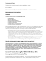
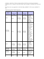
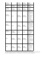
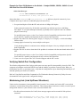
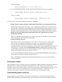
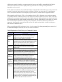
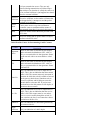
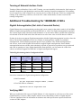
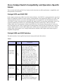
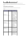
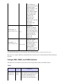
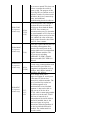
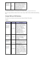
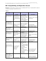
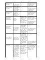
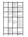
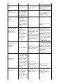
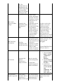
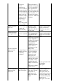
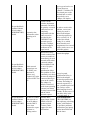
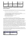
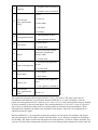
Troubleshooting Cisco Catalyst Switches to NIC
Compatibility Issues
Document ID: 17053
Introduction
Prerequisites
Requirements
Components Used
Conventions
Background Information
Purpose
Why Do Autonegotiation and Compatibility Issues Exist?
General Troubleshooting for 10/100/1000 Mbps NICs
Autonegotiation Valid Configuration Table
EtherChannel and Trunking Between Catalyst Switches and NICs
Verifying Physical Connection and Link
Verifying Switch Port Configuration
Maintaining Link (Link Up/Down Situations)
Performance Notes
Understanding Data Link Errors
Sniffer Trace
Teaming of Network Interface Cards
Additional Troubleshooting for 1000BASE−X NICs
Gigabit Autonegotiation (No Link to Connected Device)
Verifying GBIC
Cisco Catalyst Switch Compatibility and Operation−Specific Issues
Catalyst 8510 and 8540 CSR
Catalyst 6000 and 6500 Switches
Catalyst 5000 and 5500 Switches
Catalyst 4000, 2948G, and 2980G Switches
Catalyst 2950 and 3550 Switches
NIC Compatibility and Operation Issues
Appendix A: Information to Gather Before Creating a Service Request
Appendix B: Understanding How Autonegotiation Works
Networking Professionals Connection Featured Conversations
Related Information
Introduction
The purpose of this document is to cover common issues associated with network interface cards (NICs) that
interoperate with Cisco Catalyst switches. Network issues, such as slow performance and connectivity
problems, as well as Catalyst switch issues that deal with physical connectivity and data link errors, can be
related to NIC issues.
Prerequisites
Requirements
There are no specific requirements for this document.
Components Used
This document is not restricted to specific software and hardware versions.
Conventions
Refer to Cisco Technical Tips Conventions for more information on document conventions.
Background Information
Purpose
This document discusses how to troubleshoot these issues:
• Autonegotiation
• Physical Connectivity
• Port Errors (Data Link Errors)
• Continuous Link Up/Down Situations
• Gigabit Port Configuration
• Common Catalyst Switch Software Issues
• Common NIC Issues and Resolutions
When you troubleshoot NIC issues with Catalyst switches, the first step is to verify that the issue is not related
to a possible configuration issue with the Catalyst switch. For useful information that pertains to common
connectivity issues with the configuration of the Catalyst switch, refer to these documents:
• This document addresses initial connectivity delays that occur when workstations connected to
Catalyst switches are unable to log in to a network domain (Microsoft Windows NT or Novell), or are
unable to obtain a Dynamic Host Configuration Protocol (DHCP) address, due to the Catalyst switch
configuration. The first step in order to troubleshoot these scenarios is to confirm that the switch
configuration is correct, as shown in Using PortFast and Other Commands to Fix Workstation Startup
Connectivity Delays.
• Excessive data link errors cause ports on some Catalyst switches to go into an errdisabled state.
Recovering From errDisable Port State on the CatOS Platforms describes what the errdisable
state is, explains how to recover from it, and provides two examples of recovery from this state.
Why Do Autonegotiation and Compatibility Issues Exist?
Autonegotiation issues can result from nonconforming implementation, hardware incapabilities, or software
defects. When NICs or vendor switches do not conform exactly to the IEEE specification 802.3u, problems
can result. Hardware incompatibility and other issues can also exist as a result of vendor−specific advanced
features, such as autopolarity or cable integrity, which are not described in IEEE 802.3u for 10/100 Mbps
autonegotiation. Generally, if both the NIC and the switch adhere to IEEE 802.3u autonegotiation
specifications and all additional features are disabled, autonegotiation must properly negotiate speed and
duplex, and no operational issues exist.
General Troubleshooting for 10/100/1000 Mbps NICs
Autonegotiation Valid Configuration Table
Speed determination issues can result in no connectivity. However, issues with autonegotiation of duplex
generally do not result in link establishment issues. Instead, autonegotiation issues mainly result in
performance−related issues. The most common problems with NIC issues deal with speed and duplex
configuration. Table 1 summarizes all possible settings of speed and duplex for FastEthernet NICs and switch
ports.
Note: This section is only applicable for 10/100/1000 Mbps (1000BASE−T) NICs, and not 1000BASE−X
NICs.
Table 1Autonegotiation Valid Configuration
Configuration
NIC
(Speed/Duplex)
AUTO
1000 Mbps,
Full−duplex
AUTO
1000 Mbps,
Full−duplex
100 Mbps,
Full−duplex
Configuration
Resulting
Resulting NIC
Switch
Catalyst
Comments
Speed/Duplex
(Speed/Duplex)
Speed/Duplex Assuming
maximum
capability of
1000 Mbps,
1000 Mbps,
AUTO
Catalyst switch,
Full−duplex
Full−duplex
and NIC is
1000 Mbps,
full−duplex.
AUTO
1000 Mbps,
Full−duplex
1000 Mbps,
Full−duplex
Link is
established, but
the switch does
not see any
autonegotiation
information
from NIC.
Since Catalyst
switches
support only
full−duplex
operation with
1000 Mbps,
they default to
full−duplex,
and this
happens only
when operating
at 1000 Mbps.
Assuming
maximum
capability of
NIC is 1000
Mbps,
full−duplex.
1000 Mbps,
Full−duplex
1000 Mbps,
Full−duplex
1000 Mbps,
Full−duplex
1000 Mbps,
Full−duplex
1000 Mbps,
Full−duplex
1000 Mbps,
Full−duplex
1000 Mbps,
Full−duplex
No Link
No Link
AUTO
Correct Manual
Configuration
Neither side
establishes link,
due to speed
mismatch
100 Mbps,
Full−duplex
AUTO
100 Mbps,
Full−duplex
100 Mbps,
Half−duplex
10 Mbps,
Half−duplex
10 Mbps,
Half−duplex
AUTO
AUTO
1
100 Mbps,
Full−duplex
100 Mbps,
Half−duplex
Duplex
Mismatch 1
100 Mbps,
Full−duplex
100 Mbps,
Half−duplex
100 Mbps,
Full−duplex
Duplex
Mismatch 1
100 Mbps,
Full−duplex
100 Mbps,
Full−duplex
100 Mbps,
Full−duplex
AUTO
100 Mbps,
Half−duplex
100 Mbps,
Half−duplex
AUTO
100 Mbps,
Half−duplex
100 Mbps,
Half−duplex
10 Mbps,
Half−duplex
10 Mbps,
Half−duplex
No Link
100 Mbps,
Half−duplex
10 Mbps,
Half−duplex
Correct
Manual
Configuration2
Link is
established, but
switch does not
see any
autonegotiation
information
from NIC and
defaults to
half−duplex
when operating
at 10/100 Mbps.
10 Mbps,
Half−duplex
Link is
established, but
switch does not
see Fast Link
Pulse (FLP) and
defaults to 10
Mbps
half−duplex.
No Link
Neither side
establishes link,
due to speed
mismatch.
100 Mbps,
Half−duplex
Link is
established, but
NIC does not
see any
autonegotiation
information and
defaults to 100
Mbps,
half−duplex.
10 Mbps,
Half−duplex
Link is
established, but
NIC does not
see FLP and
defaults to 10
Mbps,
half−duplex.
A duplex mismatch can result in performance issues, intermittent connectivity, and loss of communication.
When you troubleshoot NIC issues, verify that the NIC and switch use a valid configuration.
2
Some third−party NIC cards can fall back to half−duplex operation mode, even though both the switchport
and NIC configuration are manually configured for 100 Mbps, full−duplex. This is because NIC
autonegotiation link detection still operates when the NIC is manually configured. This causes duplex
inconsistency between the switchport and the NIC. Symptoms include poor port performance and frame check
sequence (FCS) errors that increment on the switchport. In order to troubleshoot this issue, try to manually
configure the switchport to 100 Mbps, half−duplex. If this action resolves the connectivity problems, this NIC
issue is the possible cause. Try to update to the latest drivers for your NIC, or contact your NIC card vendor
for additional support.
Why Is It That the Speed and Duplex Cannot Be Hardcoded on Only One Link Partner?
As indicated in Table 1, a manual setup of the speed and duplex for full−duplex on one link partner results in
a duplex mismatch. This happens when you disable autonegotiation on one link partner while the other link
partner defaults to a half−duplex configuration. A duplex mismatch results in slow performance, intermittent
connectivity, data link errors, and other issues. If the intent is not to use autonegotiation, both link partners
must be manually configured for speed and duplex for full−duplex settings.
Recommended Port Configuration (Autonegotiation or Manual Configuration)
There are many opinions on the subject of autonegotiation. Previously, many engineers advised customers not
to use autonegotiation with any switch−connected device. However, improvements in the interoperation of
autonegotiation and the maturity of the technology has recently changed the view of autonegotiation and its
use. In addition, performance issues due to duplex mismatches, caused by the manual setting of speed and
duplex on only one link partner, are more common. Because of these recent issues, the use of autonegotiation
is regarded as a valid practice.
EtherChannel and Trunking Between Catalyst Switches and NICs
EtherChannel can be configured dynamically with Port Aggregation Protocol (PAgP), and trunking can also
be configured dynamically with Dynamic Trunking Protocol (DTP). Both PAgP and DTP are Cisco
proprietary protocols and supported only on Catalyst switches. If you want to configure EtherChannel or
trunking between Catalyst switches and NICs, it is recommended that you configure these features statically,
as other vendor NICs can potentially not support PAgP and DTP. On Catalyst switches, configure the
EtherChannel mode to on and trunking mode to nonegotiate, which disables the PAgP and DTP
protocols. If you configure the switch port with auto or desirable mode, it is possible you can not be
able to form the EtherChannel or trunk with NICs.
Verifying Physical Connection and Link
When you troubleshoot NIC issues, the first step is to verify physical connectivity. Visual inspection of the
switch must show a LINK light indicator when connected to a link partner. In addition, the NIC can also have
a LINK light indicator. The Command Line Interface (CLI) of the switch must be checked in ordre to verify
physical connectivity. The port in question must show connected for Catalyst OS software and line
protocol up for Cisco IOS® Software on the switch.
Example for CatOS − Catalyst 2948G, 2980G, 4000, 5000, and 6000 that Run CatOS Software
• show port modDport
Switch> (enable) show port 3/1
Port Name
Status
VLAN
−−−−−−−−−−
−−−−−−−−
−−−−−−−
3/1
notconnect
1
Level
−−−−−−−
normal
Duplex
−−−−−−−
half
Speed
Type
−−−−−− −−−−−−−−−−−−−−
100
100BaseFX MM
Example for Cisco IOS Software on the Switch − Catalyst 2900XL, 3500XL, 2948G−L3, and
6000 that Run Cisco IOS Software
• show interfaces type
Switch# show interfaces fastethernet 0/1
FastEthernet0/1 is down, line protocol is down
States other than connected and line protocol is up indicate a physical connectivity issue.
Complete these steps in order to troubleshoot physical connectivity:
1. Set speed and duplex of both the NIC and switch at 10 Mbps, full−duplex.
Is there physical connectivity? If desirable, repeat this step with the speed set to 100 Mbps,
full−duplex. To set speed and duplex manually is probably not be required in order to establish
physical connectivity.
For possible known issues, see the Cisco Catalyst Switch Compatibility and Operation−Specific
Issues and NIC Capability and Operation Issues sections of this document.
2. Replace the cable with a known good Category 5, Category 5e or Category 6 10/100/1000 Mbps
Ethernet cable.
3. Attempt physical connectivity across multiple switch ports.
Verify that the problem is consistent across multiple switch ports. Also, try multiple switches and
hubs if applicable.
4. Replace the NIC in order to determine if the problem is consistent with the same brand and model of
NIC.
For possible known issues, see the Cisco Catalyst Switch Compatibility and Operation−Specific
Issues and NIC Capability and Operation Issues sections of this document.
5. Create a service request with Cisco Technical Support and the NIC vendor.
Verifying Switch Port Configuration
The default configuration of the Catalyst switch ports can cause specific interoperability issues for NICs. The
symptoms of problems can include DHCP issues and the inability to perform a network login. When you
troubleshoot any NIC or switch port issue, verify that the configuration of port channeling and trunking is off
and that spanning tree PortFast is enabled.
Refer to Using PortFast and Other Commands to Fix Workstation Startup Connectivity Delays for more
documentation with regard to this configuration change.
Maintaining Link (Link Up/Down Situations)
Under certain circumstances, interoperability issues between Cisco switches and various NICs can result in
continuous or intermittent link up/down situations. These link up/down situations are usually a result of power
management features or jitter tolerance issues associated with the NIC.
• For link up/down situations for CatOS, these messages appear and are normal for link up/down
situations:
PAGP−5−PORTTOSPT: Port [dec]/[dec] joined bridge port [dec]/[chars]
PAGP−5−PORTFROMSPT: Port [dec]/[dec] left bridge port [dec]/[chars]
This is an example:
%PAGP−5−PORTFROMSTP:Port 3/3 left bridge port 3/3
%PAGP−5−PORTTOSTP:Port 3/3 joined bridge port 3/3
• For Cisco IOS Software−based switches, these messages appear for link up/down situations:
%LINK−3−UPDOWN: Interface interface, changed state to up
%LINK−3−UPDOWN: Interface interface, changed state to down
This is an example:
%LINK−3−UPDOWN: Interface FastEthernet0/1, changed state to up
%LINK−3−UPDOWN: Interface FastEthernet0/1, changed state to down
In order to resolve these issues, troubleshoot with these techniques:
• Disable Windows 2000 and Windows Millennium Edition (ME) power management functions.
Windows 2000 and Windows ME employ a power management capability that can disable the NIC.
When the NIC is disabled for power management, it drops the link to the switch. If there is a concern
about the link going up/down on NICs with the Windows 2000 or Windows ME operating systems,
disable the power management feature as a first step in order to troubleshoot link up/down situations.
• Disable the NIC power management functionality. Many NICs support their own power
management capability.
When you troubleshoot link up/down issues, disable this feature. For information on how to disable
power management, refer to the NIC documentation.
• Adjust switch jitter tolerance.
Jitter tolerance, based on the IEEE 802.33u−1995, clause 25, must not exceed 1.4 nanoseconds.
However, there are situations in which NICs that operat out−of−specification with respect to
excessive jitter cause link up/down situations on Catalyst 6000 and 6500 10/100 ports. The
workaround for this issue is to increase the jitter tolerance on the Catalyst 6000 and 6500 switches for
10/100 ports to 3.1 seconds. The set option debounce enable command enables the feature. As an
ultimate solution, replace the out−of−specification NICs, instead of using the debounce option. This
feature is first integrated into software version 5.3(5)CSX.
For the Catalyst 2900XL and 3500XL, the interface command carrier−delay time can be adjusted to
four seconds as a possible workaround for this same issue.
Refer to Fast Ethernet Consortium Physical Medium Dependent Test Suite for more information
about jitter tolerance.
Performance Notes
Most performance issues are related to switch port configuration, duplex mismatches, link up/down situations,
and data link errors. When you troubleshoot performance issues, review all previous sections of this
document. After you review these sections, proceed to the next section, Understanding Data Link Errors. The
final step in order to resolve any performance issue is to obtain a sniffer trace. A sniffer trace is very
conclusive with regard to any specific performance problem because it details packet transfer.
Understanding Data Link Errors
Many performance issues with NICs can be related to data link errors. Excessive errors usually indicate a
problem. When operating at a half−duplex setting, some data link errors such as FCS, alignment, runts, and
collisions are normal. Generally, a one percent ratio of errors to total traffic is acceptable for half−duplex
connections. If the ratio of errors to input packets is greater than two or three percent, performance
degradation can be noticed.
In half−duplex environments, it is possible for both the switch and the connected device to sense the wire and
transmit at exactly the same time and result in a collision. Collisions can cause runts, FCS, and alignment
errors, caused when the frame is not completely copied to the wire, which results in fragmented frames.
When operating at full−duplex, FCS, cyclic redundancy checks (CRC), alignment errors, and runt counters
are probably minimal. If the link operates at full−duplex, the collision counter is not active. If the FCS, CRC,
alignment, or runt counters increment, check for a duplex mismatch. Duplex mismatch is a situation in which
the switch operates at full−duplex and the connected device operates at half−duplex, or the other way around.
The result of a duplex mismatch is extremely slow performance, intermittent connectivity, and loss of
connection. Other possible causes of data link errors at full−duplex are bad cables, a faulty switch port, or
NIC software or hardware issues.
When you troubleshoot NIC performance issues, view the output of the show port mod/port command and
the show mac mod/port command, and note the counter information.
Table 2Explanation of CatOS show port Command Counters
Counter
Description
Alignment
Alignment errors are a count of the number of
Errors
frames received that do not end with an even
number of octets and have a bad CRC.
FCS error count is the number of frames that were
FCS
transmitted or received with a bad checksum (CRC
value) in the Ethernet frame. These frames are
dropped and not propagated onto other ports.
Xmit−Err
This is an indication that the internal transmit
buffer is full.
Rcv−Err
This is an indication that the receive buffer is full.
UnderSize These are frames that are smaller than 64 bytes,
which includes FCS, and have a good FCS value.
Single
Collisions
Multiple
Collisions
Late
Collisions
Single collisions are the number of times the
transmitting port had one collision before
successfully transmitting the frame to the media.
Multiple collisions are the number of times the
transmitting port had more than one collision before
successfully transmitting the frame to the media.
A late collision occurs when two devices transmit
at the same time and neither side of the connection
detects a collision. The reason for this occurrence is
that the time to propagate the signal from one end
of the network to another is longer than the time to
put the entire packet on the network. The two
devices that cause the late collision never see that
the other sends until after it puts the entire packet
on the network. Late collisions are detected by the
transmitter after the first time slot of the
64−byte transmit time occurs. They are only
detected during transmissions of packets longer
than 64 bytes. Its detection is exactly the same as it
is for a normal collision; it just happens later than it
does for a normal collision.
Excessive
Collisions
Carrier
Sense
Runts
Giants
Excessive collisions are the number of frames that
are dropped after 16 attempts to send the packet
resulted in 16 collisions.
Carrier sense occurs every time an Ethernet
controller wants to send data and the counter is
incremented when there is an error in the process.
These are frames smaller than 64 bytes with a bad
FCS value.
These are frames that are greater than 1518 bytes
and have a bad FCS value.
Table 3Possible Causes for Incrementing CatOS Counters
Counter
Alignment
Errors
FCS
Xmit−Err
Rcv−Err
UnderSize
Single
Collisions
Description
These are the result of collisions at half−duplex,
duplex mismatch, bad hardware (NIC, cable, or
port), or a connected device that generates frames
that do not end with on an octet and have a bad
FCS.
These are the result of collisions at half−duplex,
duplex mismatch, bad hardware (NIC, cable, or
port), or a connected device that generates frames
with bad FCS.
This is an indication of excessive input rates of
traffic. This is also an indication that the transmit
buffer is full. The counter must only increment in
situations in which the switch is unable to forward
out the port at a desired rate. Situations such as
excessive collisions and 10 Mb ports cause the
transmit buffer to become full. If you increase
speed and move the link partner to full−duplex, it
minimizes this occurrence.
This is an indication of excessive output rates of
traffic. This is also an indication that the receive
buffer is full. This counter must be zero unless
there is excessive traffic through the switch. In
some switches, the Out−Lost counter has a direct
correlation to the Rcv−Err.
This is an indication of a bad frame generated by
the connected device.
This is an indication of a half−duplex
configuration.
Multiple
Collisions
Late
Collisions
Excessive
Collisions
Carrier
Sense
Runts
Giants
This is an indication of a half−duplex
configuration.
This is an indication of faulty hardware (NIC,
cable, or switch port) or a duplex mismatch.
This is an indication of overutilization of the
switch port at half−duplex or duplex mismatch.
This is an indication of faulty hardware (NIC,
cable, or switch port).
This is an indication of the result of collisions,
duplex mismatch, IEEE 802.1Q (dot1q), or an
Inter−Switch Link Protocol (ISL) configuration
issue.
This is an indication of faulty hardware, dot1q, or
an ISL configuration issue.
Table 4Explanation of CatOS show mac Command Counters
Counter
Rcv−Unicast
Description
This is an indication of the number of unicast
packets received.
Rcv−Multicast
This is an indication of the number of
multicast packets received.
Rcv−Broadcast
This is an indication of the number of
broadcast packets received.
Xmit−Unicast
This is an indication of the number of unicast
packets transmitted.
Xmit−Multicast This is an indication of the number of
multicast packets transmitted.
Xmit−Broadcast This is an indication of the number of
broadcast packets transmitted.
Delay Exceeded
MTU−Exced
This is an indication of the number of frames
discarded because of excessive delay in the
switching process.
This is an indication that one of the devices on
the port or segment transmits more than the
allowed frame size.
In−Discard 2
Count of valid frames received which were
discarded or filtered by the forwarding
process.
Lrn−Discard 2
Packets which are forwarded and must not be
forwarded.
In−Lost
Packets which can not be received because the
input buffers are full.
Out−Lost
Packets which can not be transmitted because
the output buffers are full.
2
In−Discard and Lrn−Discard do not exist on all Catalyst platforms.
Table 5Possible Causes for Incrementing CatOS Counters
Counter
Possible Cause
Delay Exced Severe problem with the switch. Create a service
request with Cisco Technical Support.
Verify ISL and dot1q configurations. Verify
MTU−Exced another switch or router does not inject frame
over maximum transmission unit (MTU) into the
switch network.
Increments when the switch receives traffic on a
Lrn−Discard trunk for a specific VLAN while the switch does
2
not have any other ports on that VLAN. Counter
also increments when the destination address of
the packet is learned on the port on which the
packet is received.
Lrn−Discard
2
In−Lost
Out−Lost
2
This counter must remain at zero. If counter
increments, create a service request with Cisco
Technical Support.
Excessive input rate of traffic.
Excessive output rate of traffic. Increments in this
counter are more likely to occur when connected
to low−speed devices. The first step to
troubleshoot Out−Lost increments is to verify the
link partner runs 100 Mbps, full−duplex without
any errors.
In−Discard and Lrn−Discard do not exist on all Catalyst platforms.
Additional counter information can be viewed with the command show counters mod/port . The command
must be issued for a single port at a time. Refer to this document for information on the counter displayed:
• show counters Command Documentation
For additional information about the Cisco IOS Software show interfaces command counters, refer to:
• show interfaces Command Documentation
Sniffer Trace
Sniffer trace analysis can be very useful when you troubleshoot switch and NIC performance or connectivity
issues when the issues persist after all other sections of this document are reviewed. Sniffer trace analysis
reveals every packet on the wire and pinpoints the exact problem. It can be important to obtain several sniffer
traces from different ports on different switches. Generally, it is very useful to monitor or span ports rather
than spanning VLANs when you troubleshoot switch and NIC performance and connectivity issues.
Refer to Catalyst Switched Port Analyzer (SPAN) Configuration Example for more information on the use of
the Switched Port Analyzer (SPAN) feature required to obtain sniffer traces.
Teaming of Network Interface Cards
Teaming of Network Interface Cards, or NIC Teaming, can cause instability in the networks. Such setups can
introduce disruptions to the Spanning tree and can make it undergo frequent recomputations. If intermittent
loss of connectivity to NIC teamed servers occurs for devices or hosts in the same VLAN, try to disable NIC
teaming. If the connectivity stabilizes, refer to the NIC vendor documentation in order to tune the NIC
teaming configuration.
Additional Troubleshooting for 1000BASE−X NICs
Gigabit Autonegotiation (No Link to Connected Device)
Gigabit Ethernet has an autonegotiation procedure that is more extensive than what is used for 10/100 Mbps
Ethernet (Gigabit autonegotiation specification IEEE 802.3z−1998). The Gigabit autonegotiation negotiates
flow control, duplex mode, and remote fault information. You must either enable or disable link negotiation
on both ends of the link. Both ends of the link must be set to the same value or the link does not connect.
If either device does not support Gigabit autonegotiation, disable Gigabit autonegotiation in order to force the
link up. The default configuration of all Cisco switches is autonegotiation−enabled. If you disable
autonegotiation, it hides link drops and other physical layer problems. Only disable autonegotiation to
end−devices, such as older Gigabit NICs that do not support Gigabit autonegotiation. Do not disable
autonegotiation between switches unless absolutely required, as physical layer problems can go undetected
and result in spanning tree loops. Rather than disable autonegotiation, you can contact the vendor for a
software or hardware upgrade for IEEE 802.3z Gigabit autonegotiation support.
Table 6Gigabit Autonegotiation Configuration Table
Autonegotiation
Setting
Enabled
Disabled
Enabled
Disabled
NIC Gigabit
Autonegotiation
Setting
Switch Port
Gigabit Link
Alternate
Switch
Link/NIC Link
Enabled
Up
Up
Disabled
Up
Up
Disabled
Down
Up
Enabled
Up
Down
Issue these commands for Gigabit autonegotiation configuration:
• CatOS command:
set port negotiation mod/port enable | disable
• Cisco IOS Software command:
negotiation auto no negotiation auto
Verifying GBIC
When you troubleshoot link issues on Gigabit Ethernet, it is also important to verify the use of the correct
Gigabit Interface Converter (GBIC) adapter with the correct cable distance. Refer to Gigabit Interface
Converter Installation Note for information on distances and cable specifications required for different
versions of GBIC adapters.
Cisco Catalyst Switch Compatibility and Operation−Specific
Issues
These sections deal with specific Cisco Catalyst switch issues that can affect performance, compatibility, and
interoperation of certain NICs.
Catalyst 8510 and 8540 CSR
In the campus switch router (CSR) Cisco IOS Software Release 12.0(5)W5(13), autonegotiation for speed and
duplex are enabled by default. In earlier releases, autonegotiation is not supported by default. As a result, each
connected interface must be set to run in full−duplex mode. If you upgrade to Cisco IOS Software Release
12.0(5)W5(13) with a router that runs in manually full−duplex mode, you experience performance issues. The
symptoms include high collision rate, reduced throughput, and more packet drops. This is because the
Catalyst 8500 waits to autonegotiate with the connected device. Now that the connected device is forced to
run in full−duplex mode, it does not participate in autonegotiation. Based on the specification, this causes the
Catalyst 8500 interface to settle in half−duplex mode, which causes a mismatch between the device and the
Catalyst 8500 at the interface level. Catalyst 8500 interface defaults to half−duplex mode when the peer is
incapable of negotiation.
Catalyst 6000 and 6500 Switches
This table describes Cisco bug IDs found on the Catalyst 6000 and 6500 switches.
Table 7
Cisco Bug ID
CSCdm48887
( registered
customers only)
CSCdm80035
( registered
customers only)
CSCdm88013
( registered
customers only)
Resolved
In
Description
5.2.3,
5.3.1a
When a port goes into the
errdisable state on a Catalyst
6000 or 6500, the switch
inadvertently learns the MAC
addresses of other devices to be
learned from the errdisable
port. The errdisable state is
caused by excessive late collisions
on a port. Since all traffic on that
VLAN is forwarded incorrectly out
of the incorrect port, there is a loss
of connectivity. This errdisable
state can appear as a result of a
duplex mismatch or faulty NIC.
5.2.3,
5.3.1a
When a Gigabit connection is reset
on a Catalyst 6000 or 6500, the
connection can potentially not
reconnect. A symptom of this issue
can be that a Gigabit NIC does not
connect after reset or disconnect.
5.2.3,
5.3.1a
Occasionally, host NICs connected
to WS−X6248−TEL or
WS−X6248−RJ−45 modules can
incorrectly revert to half−duplex
after an autonegotiation failure.
For detailed information on Cisco bug IDs, refer to the Bug Toolkit
( registered customers only) .
Refer to Cisco Catalyst 6500 Series Switches Release Notes for more Catalyst 6000 and 6500 documented
bug fixes.
Catalyst 5000 and 5500 Switches
This table lists several known issues found on the Catalyst 5000 and 5500 switches.
Table 8
Cisco Bug ID
CSCdt28585
(
registered customers only)
CSCdr50629
(
registered customers only)
Description
Directly connected
hosts (PCs, routers, and
servers) can indicate a
connected state in
the output of a show
port command, but do
not forward
Xmit−Broadcast
frames. This causes
connectivity issues that
are only fixed when you
issue the set port
disable mod/port and
the set port enable
mod/port commands.
5.5(3)
Ports on WS−X5225R,
WS−X5234, and
WS−X5201R modules
do not transmit unicast
frames after a scheduled
test of the packet
buffers. The
workaround is to
disable the packet
buffer test.
4.5(7), 5.4(2)
The WS−X5225R and
WS−X5234 modules
fail to negotiate the
duplex mode correctly
after a system reset or
power cycle with Sun
workstations Ultra 5.
(
registered customers only)
CSCdm51653
5.5(6)
(
registered customers only)
CSCdr03818
Resolved In
4.5(3), 5.1(2a) Autonegotiation
between Sun 10/100
NICs and certain
Catalyst 5000 family
modules (such as the
WS−X5225R) can
result in speed or duplex
mismatches under
certain conditions. The
problem typically
occurs after the module
is reset or the switch
port is disabled and
reenabled. The
workaround is to
disconnect and
reconnect the cable that
connects the
workstation to the
switch port.
CSCdk32984
3.2(2), 4.1(3)
Under heavy traffic
conditions, ports 1
through 24 (or ports 25
through 48) of the
48−port, 10BASE−T
Ethernet module
(WS−X5012) can stop
transmitting frames.
(
registered customers only)
CSCdj82035
4.2(2)
The 48−port,
10BASE−T Ethernet
module (WS−X5012)
incorrectly drops valid
frames with dribble bits
(extra bits added to
frames by some end
stations and
transceivers).
(
registered customers only)
For detailed information on Cisco bug IDs, refer to the Bug Toolkit
( registered customers only) .
Refer to Cisco Catalyst 5000 Series Switches Release Notes for more Catalyst 5000 and 5500 documented
bug fixes.
Catalyst 4000, 2948G, and 2980G Switches
This table lists several known issues found on the Catalyst 4000, 2948G, and 2980G switches.
Table 9
Bug ID
CSCds38973
( registered
customers only)
Resolved
In
4.5(8),
5.2(7),
5.5(2)
Description
The Catalyst 2948G and Catalyst
4000 switches can experience issues
with total or intermittent loss of
connectivity. The frequency of
these issues can vary from once a
day to once a month. This issue can
reoccur even after the switch is
power cycled. The purpose of this
Cisco bug ID is to combine several
software reworks, fixes that resolve
and reduce the loss of connectivity
issues, and additional
troubleshooting checks in software.
CSCdr37645
( registered
customers only)
CSCdm38405
( registered
customers only)
CSCdm51653
( registered
customers only)
CSCdt80707
( registered
customers only)
4.5(8),
5.5(2),
6.1(1)
An invalid packet with a length of
less than 64 bytes received on a
10/100 port causes both the Runts
and FCS−Error counters to
increment on the port. To determine
the actual number of FCS−Errors on
valid length packets received on the
port, subtract the value of the port
Runts counter from the value of the
port FCS−Error counter.
5.1(1)
Some Sun Gigabit Ethernet NICs do
not reliably autonegotiate flow
control with certain ports on the
Catalyst 4000 series oversubscribed
Gigabit Ethernet modules. The
18−port server switching
1000BASE−X (GBIC) Gigabit
Ethernet module (WS−X4418) is
affected.
4.5(3),
5.1(2a)
5.5.7,
6.1.3,
6.2.1
In some cases, autonegotiation with
some Sun NICs can result in a
nonoptimal configuration (such as
10 Mbps, half−duplex instead of
100 Mbps, full−duplex).
On a Catalyst 4006 with a
Supervisor Engine II, switch ports
in the same VLAN can lose
connectivity with one another. The
loss of connectivity results in a
VLAN that appears to be
partitioned into several isolated
segments. A host can be able to
ping one set of devices in its
VLAN, while it cannot ping another
set of devices in the same VLAN.
This loss of connectivity is
independent of the slot in which a
linecard is installed; that is, the
same set of ports on a given
linecard are affected regardless of
the slot in which the linecard is
installed. The workaround is to
reset the switch.
CSCds89148
( registered
customers only)
5.5.6,
6.2.1
Xmit−Err counter increments on
unconnected ports for unexplained
reasons. The bug also resolves an
issue of high−CPU utilization
conditions that can be caused by
unconnected ports that are
configured as host ports.
For detailed information on Cisco bug IDs, refer to the Bug Toolkit
( registered customers only) .
Refer to Catalyst 4500 Series Release Notes for more Catalyst 2948G, 2980G, and 4000 documented bug
fixes.
Catalyst 2950 and 3550 Switches
This table lists several known issues found on the Catalyst 2950 and 3550 switches.
Table 10
Cisco Bug ID
CSCdz44520
( registered
customers only)
CSCdz32789
( registered
customers only)
CSCdy72718
( registered
customers only)
CSCea36322
( registered
customers only)
Resolved In
Description
The Catalyst 3550−24PWR
inline power interfaces do not
link up to certain 10/100/1000
interfaces configured as
auto/auto. To connect the
12.1(13)EA1 Catalyst 3550−24PWR inline
power interfaces to a
10/100/1000 interface
configured as auto/auto on a
Catalyst 3550−12G or
3550−12T does not work.
The link to certain NICs fails to
come up when the switch port is
12.1(13)EA1 hardcoded to 100 Mbps,
full−duplex or 100 Mbps,
half−duplex.
The switch port does not receive
packets if the port is hardcoded
12.1(13)EA1
to a speed of 100, however it
transmits properly.
If a 10/100 port on the Catalyst
3550−24PWR switch is
connected to a Gigabit Ethernet
NIC, with the speed/duplex
setting set to auto, and the port
12.1(14)EA1
speed changed from 100 Mbps
to 10 Mbps, or from 10 Mbps to
100 Mbps, the link between the
port and the NIC can potentially
not come up.
For detailed information on Cisco bug IDs, refer to the Bug Toolkit
( registered customers only) .
NIC Compatibility and Operation Issues
Disclaimer: Use this table as a guide in order to troubleshoot NIC issues. Consult the NIC vendor for
verification and proper resolution of the issue.
Table 11
NIC
Model/Manufacture
Apple Macintosh
G3
Symptom
Intermittently loses
network services
when the built−in
Ethernet interface is
used.
Apple Macintosh,
Power Macintosh
G3, and Powerbook Unable to set speed
G3
and duplex of
built−in Ethernet
interface manually.
Apple Macintosh
OS with Open
Transport 2.5.1 and
Unable to obtain
2.5.2
DHCP address from
DHCP server.
Apple Macintosh
Unable to determine
Built−In Ethernet
hardware MAC
address.
Apple Macintosh
Performance Issues
and NuBus
Built−in Ethernet
interfaces
outperform NuBus
Ethernet cards.
Apple Powerbook
G3/G4 with Internal Slow performance
NIC
when large file
transfers are
performed.
Various Apple
G3/G4 Laptops and
Workstations with
Internal NICs
Slow performance.
Description
Resolution
Driver versions
earlier than 2.04 can
experience this issue. Upgrade to driver version
Contact vendor
2.04 or later.
technical support for
more information.
Apple Speed/Duplex
tool is required to
manually set
speed/duplex of
Ethernet interface.
Upon bootup,
Macintosh can fail to
obtain IP address
In order to
from DHCP server.
troubleshoot network
connectivity issues,
host MAC address
can be required.
Concern of maximum
data transfer rate
possible with the
built−in Ethernet.
Some NICs can
operate
out−of−specification,
as published in IEEE
802.3. Some
Catalysts are more
tolerant of
out−of−spec NICs
and do not notice any
performance
degradation.
Notable slow
performance.
Download Apple
Speed/Duplex tool from
Apple support website.
See Apple technical
information library
article 25049.
Contact vendor technical
support.
See Apple technical
information library
article 12000.
Use of external or PC
card. Contact Apple
technical support.
Upgrade to latest NIC
driver and load Duplexer
utility. Verify
autonegotiation settings.
AsantéFast 10/100
PCI Adapter
AsantéFast 10/100
PCI Adapter
AsantéFast 10/100
PCI Adapter
Asanté GigaNIC
1064SX PCI
Card−Macintosh
Asanté GigaNIC
1064SX PCI
Card−Macintosh
3Com 3C574/575
PCMCIA 10/100
3Com 3C595
See technical document
TID1084 at Asanté
support website.
Slow login or fails
to log in to server.
Numerous CRC and
FCS errors reported
on switch when
connected to Power
Macintosh 9500.
See technical document
TID1109 at Asanté
support website.
Slow network
throughput after
Macintosh OS 8.5
or 8.6 upgrade.
Network
performance
fluctuates.
See technical document
TID1976 at Asanté
support website.
When the energy
saver mode is active
under OS 8.6, the
network speed
becomes quite slow
as soon as the
monitor goes dim.
Customers report
AppleShare IP
Slow performance servers slow down
with AppleShare IP and eventually crash
over time. This
servers and PCI
occurs with both
Ethernet cards.
built−in Ethernet and
various PCI cards.
Turn off the energy saver
mode in the control
panel. The network speed
remains constant.
See technical document
TID2095 at Asanté
support website.
See technical document
TID2227 at Asanté
support website.
The 3C574/3C575
experiences slow
performance when
connecting at 10 MB
with Catalyst 2948G,
Extremely slow
performance when 2980G, 4000, 5000,
operating at 10 MB. and 6000 switches.
This issue is caused
Upgrade to the latest NIC
by the NIC doing
card driver and disable
autopolarity upon
autopolarity.
linkup.
FCS or alignment
errors recorded on
the switch. Noted
slower performance.
When the 3C595
adapter is used in
100 MB,
half−duplex. This
problem usually
only represents one
percent to two
percent of the total
FCS or alignment
errors when the
3C595 adapter is used
in 100 MB,
half−duplex. This
problem usually
represents one
percent to two percent
of the total traffic.
Upgrade to the latest NIC
driver and disable Bus
Master. These steps
reduce FCS and
alignment errors.
traffic.
3Com
3C905/3C905B
3Com
3C905/3C905B
3Com 3C905B
3Com 3C905C
3C905CX−TX−M
3Com 3C980
Intermittent DHCP
issues.
Despite the proper
configuration of
Catalyst switch ports,
workstations still
Upgrade to driver version
experience some
4.01b or later, which
intermittent DHCP
resolves DHCP issues.
issues.
Despite the proper
configuration of
Unable to log in to
Catalyst switch ports,
Novell Internetwork
workstations still
Packet Exchange
experience
(IPX) network.
intermittent Novell
IPX login issues.
Notable slow
performance when
Slow performance large files are
when large files are received. Problem
only occurs with
received.
standard Microsoft
NT 4.0, regardless of
service pack.
Upgrade to driver 4.01b
or later, which resolves
IPX autoframe−type
issues. Alternatively,
manually configure
workstations for IPX
frame type.
Download latest driver
from 3Com technical
support.
Load latest driver and
diagnostic tools available
Layer 2 (L2) errors
from 3Com. Test
reported on switch
performance
port (FCS,
back−to−back between
alignment, CRC,
two PCs, and note errors
Under normal
and runts), and slow
conditions, a Catalyst on diagnostic tools.
performance on
that reports numerous Errors reported, such as
high−speed
transmit under−run and
L2 (physical) errors
workstations.
on ports connected to receive over−run, cause
physical layers to be
3C905C NIC
reported by the switch
adapters.
and minor performance
issues. For more details,
refer to Cisco bug ID
CSCdt68700 (
registered customers only) .
The link fails to
come up when the
switch port is
hardcoded to 100
Mbps, full−duplex
or 100 Mbps,
half−duplex, and
the NIC is set to
autonegotiate.
Data corruption
with Novell.
Refer to Cisco bug ID
CSCdz32789 (
registered customers only)
.
Upgrade to driver version
5.4, and in the advanced
NIC properties, set
LnkChk to enable. The
driver can be downloaded
Refer to 3Com technical
from 3Com .
support reference
1.0.33921641.2241835.
3Com
3Com
3C985/3C985B
3Com
3C985/3C985B
3Com 3C905C or
3C920 integrated
NIC on Dell
Dimension XPS
Compaq Netflex−3
Model NIC
Adapters
Dell Optiplex
GX200
Dell Precision
420/530/620
3C985/3C985B
Novell 5.0 issues
Clients are unable
to log in or browse
server, but pings
work correctly.
Refer to 3Com technical
support reference
2.0.4428387.2305072.
Packets larger than
Ethernet MTU
(1518 bytes) are
generated. These
packets are noted as
giants on Catalyst
switches.
Network
connectivity is
dropped every 2›
minutes or the
network card must
be reinitialized
several times to
gain network
connectivity.
Slow performance.
The link flaps when
it connects to a Dell
Optiplex GX200 PC
(Intel Pro 10/100).
The NIC works
properly when the
PC is turned off, but
when it is turned
back on, the flap
occurs.
Refer to 3Com technical
support reference
1.0.16744826.2027011.
Contact 3Com technical
support.
A 3C905C or 3C920
integrated NIC on
Dell Dimension XPS
can experience
network connectivity
issues when Windows
2000 is run due to a
power management
issue.
Disable all power
management functions.
Contact Dell for details
on how to disable power
management or for more
details about this issue.
For more documentation,
refer to 3Com technical
support reference
2.0.47464140.2853794.
Autonegotiation can
fail to Catalyst 5000
and 5500 switches.
This problem is resolved
in software release 4.5(1)
and later for the Catalyst
5000 and 5500 switches.
For more details, refer to
Cisco bug ID
CSCdk87853 (
registered customers only) .
For more details,
refer to Cisco bug ID
CSCdz60677 (
registered customers only)
.
When connecting to Manufactured
the Catalyst 2950
between May 21 and
switch with an
August 1, 2001.
autonegotiation
link, it continuously
flaps and the
autonegotiation link
Upgrade to the latest
drivers from Dell.
Contact Dell technical
support and Cisco
Technical Support for
more details.
fails. The
motherboards were
manufactured with
an Intel Chipset that
are incompatible
with Cisco switches
and Netgear hubs.
IBM 10/100
EtherJet CardBus
Adapter
IBM ThinClient
Workstations
Intel Pro/100
Extremely slow
performance when
operating at 10
Mbps.
Certain 10/100
switches implement
automatic correction
for polarity−reversed
cables that are not
completely
compatible with the
same correction
provided by the IBM
10/100 EtherJet
CardBus Adapter. If
the network speed is
forced to 10 Mbps,
severe throughput
problems can be
experienced.
In order to resolve this
problem, a new Auto
Polarity keyword is
added in the adapter
advanced properties. If
needed, the default
setting of ON, which
means that the card
compensates for reversed
cables, can be set to OFF
in order to disable
Workstations earlier
polarity correction. This
than Service Pack 3.0
restores normal
bounce the link on the
throughput.
switch after
Link flaps
continuous use when
continuously after
extended operation. attached to Catalyst
2948G or 4000
Upgrade IBM ThinClient
switches on software to Service Pack 3.0.
version 6.x and later.
Consistent link
up/down
connections to
Catalyst switches.
Intel Pro/1000 T
When an Intel
Gigabit Copper NIC Pro/1000 T NIC is
connected to a
Catalyst switch, you
May be caused by
power management.
Contact Intel
technical support for
further information.
The interoperability
issue arises from the
implementation of
Carrier Extension.
1. Choose Control
Panel > System
> Hardware >
Device
Manager.
2. Choose Network
Adapters > Intel
Pro 100 +.
3. At the Power
Management tab,
uncheck Allow
the
computer to
turn off
this device .
Contact Intel technical
support for the latest
driver.
can see poor
network
connections or
excessive numbers
of dropped packets.
The interoperability
issue arises when a
module with a ten
bit interface (TBI)
transmits an odd
byte packet to a
receiver with a
Gigabit
media−independent
interface (GMII).
Sun Microsystems
QFE Card
Sun Microsystems
v1.1 Gigabit Cards
Xircom CreditCard
Ethernet 10/100
CE3B−100
Xircom CreditCard
Ethernet 10/100
CE3B−100
Carrier Extension is
detailed in subsection
35.2.3.5 in the IEEE
802.3 specification.
Carrier Extension can
be used to pad the last
byte of a packet, so
the packet is aligned
on an even−numbered
boundary.
Manually setting
Unable to manually
speed and duplex
set speed and
only affects the first
duplex correctly.
of four ports.
Unable to establish
link.
Not negotiating or
operating correctly
at 100 Mbps,
full−duplex.
Not negotiating 10
Mbps full−duplex.
Contact vendor technical
support to obtain the
latest driver to resolve
the issue.
V1.1 can potentially
not establish link to
switch.
Full−duplex operation
is only supported at
10 Mbps. Full−duplex
is not supported at
100 Mbps. The
LineMode keyword
has no effect on
performance at 100
Mbps. If the
LineSpeed keyword
is set to 100 Mbps
and the LineMode
keyword is set to
full−duplex, the
LineMode keyword is
ignored. Full−duplex
at 10 Mbps is only
available when the
adapter is connected
to a
full−duplex−capable
switch or hub.
Contact vendor technical
support or v2.0 Gigabit
Card.
The CE3 and, in some
cases, the CE3B are
not capable of
negotiating to 10
Mbps, full−duplex
mode.
On these adapters, in
order to operate in
full−duplex mode, the
LineSpeed keyword must
be set to 10 Mbps, and
the LineMode keyword
must be set to
full−duplex. The cable
Do not operate this NIC
at 100 Mbps,
full−duplex.
type keyword can be set
to Auto Detect or
10BASE−T/100BaseTX.
The related port on the
attached hub or switch
must also be set to
10Mbps, full−duplex.
Xircom RealPort2
CardBus Ethernet
10/100 Adapter
(R2BE/RBE/CBE)
Models
Xircom RealPort2
CardBus Ethernet
10/100 Adapter
(R2BE/RBE/CBE)
Models
Xircom RealPort2
CardBus Ethernet
10/100 Adapter
(R2BE/RBE/CBE)
Models
Extremely slow
performance when
operating at 10
Mbps.
Certain 10/100
switches implement
automatic correction
for polarity−reversed
cables that are not
completely
compatible with the
same correction
provided by the
CBE/RBE. If the
network speed is
forced to 10 Mbps,
severe throughput
problems can be
experienced.
Initialization delay.
Certain switches and
routers are unable to
immediately forward
network traffic when
a network adapter
first establishes link
to one of its ports
Initial network
because of
connections can
initialization delays.
fail. DHCP can
This problem is most
obtain an IP
commonly seen when
address, and
Windows NT login the network adapter is
and Novell IPX can connected directly to
ports on the switch.
fail.
The adapter, by
default, when used
under some operating
systems, has almost
no delay between link
and the initial
network request.
Not able to connect
to the network or
get an IP address
from the DHCP
server when
connected to a port
replicator or
docking station.
Possible Basic
Input/Output System
(BIOS) or driver
update required.
Contact vendor
support for more
information.
In order to resolve this
problem, a new Auto
Polarity keyword is
added in the adapter
advanced properties in
driver version 3.01. If
needed, the default
setting of ON, which
means that the card
compensates for reversed
cables, can be set to OFF
to disable polarity
correction. This restores
normal throughput.
A new keyword,
Initialization Delay, is
added to the adapter
advanced properties that
prevents forwarding of
network requests for a
user−selectable period of
time. Delays can be
added ranging from 10
seconds. In most cases, if
you add a delay in the
1› second range, it
If you attempt
to use a
resolves
the problem.
CBE/CBE2/RBE in a
port replicator or docking
station, with Windows
95, and have problems,
confirm that your laptop
has the latest BIOS and
that the latest
manufacturer patches and
utility software are
installed.
Xircom XE2000
PCMCIA NIC
Known limitation of
Does not
NIC only
XE2000 NIC. Refer to
autonegotiate to 100 autonegotiates to 100
the XE2000 release
Mbps, full−duplex. Mbps, half−duplex.
notes.
Appendix A: Information to Gather Before Creating a
Service Request
If the troubleshooting procedure outlined in this document does not resolve your issue, you need to create a
service request with Cisco Technical Support. Before you create a service request, gather this information:
1. Identify the specific problem with NIC−to−switch interoperability.
For example, is the problem only with DHCP, Novell IPX, login, or performance?
2. Issue the show tech−support command from all affected Cisco devices, if applicable; or, issue the
show module, show config, show version, or the show port commands.
3. Know the make and model of the NIC.
4. Know the operating system and the NIC driver version.
5. Verify the consistency of the problem.
For example, does the problem occur across multiple Catalyst switches?
Appendix B: Understanding How Autonegotiation Works
Autonegotiation uses a modified version of the link integrity test that is used for 10BASE−T devices to
negotiate speed and exchange other autonegotiation parameters. The original 10BASE−T link integrity test is
referred to as Normal Link Pulse (NLP). The modified version of the link integrity test for 10/100 Mbps
autonegotiation is referred to as FLP. The 10BASE−T devices expect a burst pulse every 16 (+/− 8)
milliseconds (msec) as part of the link integrity test. FLP for 10/100 Mbps autonegotiation sends these bursts
every 16 (+/− 8) msec with the additional pulses every 62.5 (+/− 7) microseconds. The pulses within the burst
sequence generate code words that are used for compatibility exchanges between link partners. This process
of FLP used in autonegotiation maintains backward compatibility with existing 10BASE−T connections, with
the pulse burst every 16 (+/− 8) msec to comply with the link integrity test for normal 10BASE−T hardware.
If a device sends FLP and only receives NLP, the hardware immediately ceases transmission of the FLP and
enables the standard 10BASE−T hardware to continue 10BASE−T operation.
This table describes the possible programmable options of the control register for a FastEthernet interface.
These options determine how the FastEthernet interface functions when connected to a link partner. The 0 in
the Bits column refers to the programmable register address, and the decimal number after the 0 refers to the
bit placement within the 16−bit register.
Table 12Physical Interface (PHY) Control Register Programmable Options
Bits
0.15
Name
Description
1 = PHY reset
Reset
0 = normal mode
0.14
1 = loopback mode switched on
Loopback
0 = loopback mode switched off
0.6 0.13
0.13
Rate Selection
(least−significant bit
[LSB])
1 1 reserved
1 0 1000 Mbps
0 1 100 Mbps
0 0 10 Mbps
0.12
1 = autonegotiaton enabled
Autonegotiation Enable
0 = autonegotiation disabled
0.11
1 = power down
Power Down
0 = normal down
0.10
Isolated
1 = PHY electrically isolated
from media−independent
interface (MII)
0 = normal mode
0.9
Restart Autonegotiation
1 = restart the autonegotiation
process
0 = normal mode
0.8
1 = full−duplex
Duplex Mode
0 = half−duplex
0.7
Collision Test
1 = collision (COL) signal test
active
0 = COL signal test switched off
0.6
Rate Selection
(most−significant bit
[MSB])
See bit 0.13
The register bits relevant to this document include 0.13, 0.12, 0.8, and 0.6. The other register bits are
documented in the IEEE 802.3u specification. Based on IEEE 802.3u, in order to manually set the rate
(speed), the autonegotiation bit, 0.12, must be set to a value of 0. As a result, autonegotiation must be disabled
in order to manually set the speed and duplex. If the autonegotiation bit 0.12 is set to a a value of 1, bits 0.13
and 0.8 have no significance, and the link uses autonegotiation to determine the speed and duplex. When
autonegotiation is disabled, the default value for duplex is half−duplex, unless the 0.8 is programmed to 1,
which represents full−duplex.
Based on IEEE 802.3u, it is not possible to manually configure one link partner for 100 Mbps, full−duplex
and still autonegotiate to full−duplex with the other link partner. If you attempt to configure one link partner
for 100 Mbps, full−duplex and the other link partner for autonegotiation, it results in a duplex mismatch. This
is because one link partner autonegotiates and does not see any autonegotiation parameters from the other link
partner and defaults to half−duplex.
As described in Appendix B: Understanding How Autonegotiation Works, pulses within the FLP are used to
derive code words that exchange link partner capabilities. The first code word exchanged is referred to as the
base page. It informs each link partner of the message type, IEEE 802.3 or IEEE 802.9a, and a technology
ability field. This technology ability field is encoded to exchange the maximum operational speed and duplex
of each link partner.
Networking Professionals Connection Featured
Conversations
Networking Professionals Connection is a forum for networking professionals to share questions, suggestions,
and information about networking solutions, products, and technologies. The featured links are some of the
most recent conversations available in this technology.
NetPro Discussion Forums − Featured Conversations for LAN
Network Infrastructure: LAN Routing and Switching
Network Infrastructure: Getting Started with LANs
Related Information
• Configuring and Troubleshooting Ethernet 10/100/1000Mb Half/Full Duplex Auto−Negotiation
• LAN Product Support Pages
• LAN Switching Technology Support
• Technical Support & Documentation − Cisco Systems
All contents are Copyright © 2006−2007 Cisco Systems, Inc. All rights reserved. Important Notices and Privacy Statement.
Updated: Aug 30, 2005
Document ID: 17053