1
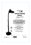
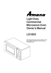
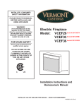
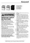
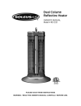
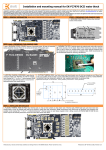
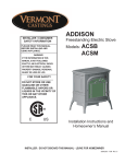
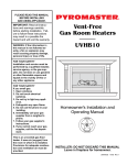
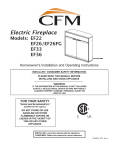
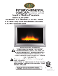
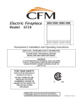
INSTALLER / CONSUMER
SAFETY INFORMATION
PLEASE READ THIS MANUAL
BEFORE INSTALLING AND
USING APPLIANCE
Electric Fireplace
Model: HEF22
HEF26
HEF33
WARNING!
IF THE INFORMATION IN THIS
MANUAL IS NOT FOLLOWED
EXACTLY, AN ELECTRICAL SHOCK
OR FIRE MAY RESULT CAUSING
PROPERTY DAMAGE, PERSONAL
INJURY OR LOSS OF LIFE.
FOR YOUR SAFETY
Service must be performed by a
qualified service agency.
DO NOT STORE OR USE
GASOLINE OR OTHER
FLAMMABLE VAPORS OR
LIQUIDS IN THE VICINITY OF
THIS OR ANY OTHER
APPLIANCE.
Installation Instructions and
Homeowners Manual
C
US
INSTALLER: DO NOT DISCARD THIS MANUAL - LEAVE FOR HOMEOWNER
10008388 8/06 Rev. 5
STOP!
NO NEED TO RETURN TO THE STORE
Questions with the Assembly?
Require Parts Information?
Product Under Manufacturer’s Warranty?
Call Toll-Free
US: 1-800-668-5323
Canada: 1-800-668-5323
Monday to Friday 9:00 A.M. to 5:00 P.M. E.S.T.
TO HELP US HELP YOU
Fill in the Information Below:
Retain This Owner’s Manual and Proof of Purchase For Future Reference
Date of Purchase
Model Number
Product Serial Number
MODEL NUMBER AND PRODUCT SERIAL NUMBER CAN BE
FOUND ON THE CERTIFICATION LABEL OF YOUR FIREPLACE
2
10008388
Table of Contents
PLEASE READ THE INSTALLATION & OPERATING INSTRUCTIONS
BEFORE USING THIS APPLIANCE
Thank you and congratulations on your purchase of a CFM Corporation electric fireplace.
IMPORTANT: Read all instructions and warnings carefully before starting installation. Failure to follow these
instructions may result in a possible electric shock, fire hazard and will void the warranty.
Installation Instructions
General . . . . . . . . . . . . . . . . . . . . . . . . . . . . . . . . . . . . . . . . . . . . . . . . . . . . . . . . .4
Locating Your Fireplace . . . . . . . . . . . . . . . . . . . . . . . . . . . . . . . . . . . . . . . . . . . . .4
Clearance to Combustibles . . . . . . . . . . . . . . . . . . . . . . . . . . . . . . . . . . . . . . . . . .4
Cabinet Installations . . . . . . . . . . . . . . . . . . . . . . . . . . . . . . . . . . . . . . . . . . . . . . .4
Fireplace Dimensions . . . . . . . . . . . . . . . . . . . . . . . . . . . . . . . . . . . . . . . . . . . . . .5
Electrical Specifications . . . . . . . . . . . . . . . . . . . . . . . . . . . . . . . . . . . . . . . . . . . . .5
Electrical Connection . . . . . . . . . . . . . . . . . . . . . . . . . . . . . . . . . . . . . . . . . . . . . . .6
Grounding Instructions . . . . . . . . . . . . . . . . . . . . . . . . . . . . . . . . . . . . . . . . . . . . .6
Direct (Hard) Wiring Electric Fireplace . . . . . . . . . . . . . . . . . . . . . . . . . . . . . . . . .6
Service Instructions
Removing Front Cover . . . . . . . . . . . . . . . . . . . . . . . . . . . . . . . . . . . . . . . . . . . . .8
Glass Information . . . . . . . . . . . . . . . . . . . . . . . . . . . . . . . . . . . . . . . . . . . . . . . . .8
Replacing the Light Bulbs . . . . . . . . . . . . . . . . . . . . . . . . . . . . . . . . . . . . . . . . . . .9
Maintenance of Motors . . . . . . . . . . . . . . . . . . . . . . . . . . . . . . . . . . . . . . . . . . . .10
Cleaning . . . . . . . . . . . . . . . . . . . . . . . . . . . . . . . . . . . . . . . . . . . . . . . . . . . . . . .10
Electrical Wiring Diagram . . . . . . . . . . . . . . . . . . . . . . . . . . . . . . . . . . . . . . . . . .10
Operating Instructions
Flame Speed Control . . . . . . . . . . . . . . . . . . . . . . . . . . . . . . . . . . . . . . . . . . . . . .11
Heater Control . . . . . . . . . . . . . . . . . . . . . . . . . . . . . . . . . . . . . . . . . . . . . . . . . . .12
Wood Burning/Crackling Sound Effect . . . . . . . . . . . . . . . . . . . . . . . . . . . . . . . .12
Overhead Light . . . . . . . . . . . . . . . . . . . . . . . . . . . . . . . . . . . . . . . . . . . . . . . . . .12
Replacement Parts . . . . . . . . . . . . . . . . . . . . . . . . . . . . . . . . . . . . . . . . . . . . . . . . . . . . .13
Warranty . . . . . . . . . . . . . . . . . . . . . . . . . . . . . . . . . . . . . . . . . . . . . . . . . . . . . . . . . . . . . .15
10008388
3
Installation Instructions
General
1. Read all instructions before using this appliance.
2. This appliance is hot when in use. To avoid burns, do not
let bare skin touch hot surfaces. If provided, use handles
when moving this appliance. Keep combustible materials,
such as furniture, pillows, bedding, papers, clothes and curtains at least 3 feet (914mm) from the front of this appliance.
3. CAUTION: Extreme caution is necessary when any
heater is used by or near children or invalids and whenever the heater is left operating unattended.
4. If possible always unplug this appliance when not in use.
5. Do not operate any heater with a damaged cord or plug or
after the appliance malfunctions, has been dropped or damaged in any manner.
6. Any repairs to this appliance should be carried out by a
qualified service person.
7. Under no circumstances should this appliance be modified.
Parts having to be removed for servicing must be replaced
prior to operating this stove again.
8. Do not use outdoors.
9. This heater is not intended for use in bathrooms, laundry
areas and similar indoor locations. Never locate this appliance where it may fall into a bathtub or other water container.
10.Do not run cord under carpeting. Do not cover cord with
throw rugs, runners or the like. Arrange cord away from
traffic areas and where it will not be tripped over.
11.To disconnect this appliance, turn controls to the off position, then remove plug from outlet.
12.Connect to properly grounded outlets only.
13.This appliance, when installed must be electrically grounded
in accordance with local codes, with the current CSA C22.1
Canadian Electrical codes or for USA installations, follow
local codes and the National Electric Code, ANSI/NFPA No.
70.
14.Do not insert or allow foreign objects to enter any ventilation
or exhaust opening as this may cause an electric shock,
fire or damage the appliance.
15.To prevent possible fire, do not block air intakes or exhaust
in any manner. Do not use on soft surfaces, like a bed,
where openings may become blocked.
16.This appliance has hot and arcing or sparking parts inside.
Do not use it in areas where gasoline, paint or flammable
liquids are used or stored. This appliance should not be
used as a drying rack for clothing, nor should Christmas
stockings or decorations be hung on or near it.
17.Use this appliance only as described in this manual. Any
other use not recommended by the manufacturer may
cause fire, electric shock or injury to persons.
18.Avoid the use of an extension cord because of the risk of
overheating the cord and the risk of fire. Extension cords
are for temporary use only. If an extension cord must be
used, it must be UL/CSA certified, rated at 15A (1875W),
125V maximum with 14 AWG minimum and constructed of
two current carrying conductors with ground. A heavy duty
extension cord with the shortest length possible for the
connection is recommended and must not be longer than
50 ft. (15.2 m). Do not coil or cover the extension cord.
Locating Your Fireplace
Your new fireplace may be installed in a prefabricated
cabinet available from your dealer.
When choosing a location for your new fireplace, ensure
the general instructions are followed. Also, for best effect
install the fireplace out of direct sunlight.
Clearance to Combustibles
Sides . . . . . . . . . . . . . . . . . . . 0” (0 mm)
Floor . . . . . . . . . . . . . . . . . . . .0” (0 mm)
Top . . . . . . . . . . . . . . . . . . . . .0” (0 mm)
Cabinet Installations
Cabinets are available from your dealer which allow for fast,
convenient installation of your fireplace against existing walls.
For instructions on handling and assembly of your cabinet,
refer to separate installation instructions that come with the
cabinet.
If it is necessary to secure your fireplace into a cabinet as for
installations in a recreational vehicle, the fireplace may be
secured by this method (hardware not supplied). Only units
with fixed glass front doors are recommended for installing in a
recreational vehicle. Refer to Pages 13 and 14 with items 7a
and 7b. The instructions below apply:
Remove the glass door from the unit and set aside. 3/16” (5
mm) clearance holes, two (2) per side must be drilled through
the fireplace sides for #8 x 3/4” long black oxide wood screws
or similar. The mounting holes can be located on left and right
sides approximately 2” (51 mm) from the top and 5” (127 mm)
from the bottom of the glass door area. The mounting hole
location distance from the front of the unit must not interfere
with the glass door and the refractory (brick pattern) when reinstalled. If necessary, modify the cabinet for the mounting
screws to attach. Double check the mounting hole’s locations
on the fireplace before drilling. A small 1/16” (2 mm) pilot hole
or center punch before drilling is recommended. Mark and drill
from the outside to avoid marking or damaging the interior of
the fireplace. Tighten the screws evenly so the unit remains
centered in the opening and without distorting the sides of the
fireplace unit. It is advisable to place wood shims or similar
between the fireplace sides and the cabinet to prevent distortion when tightening the screws. 1/2” (13 mm) Velcro strips for
securing the log to the grate tines and away from the screen
are recommended.
SAVE THESE INSTRUCTIONS
4
10008388
Fireplace Dimensions
1” (25 mm)
C
F
J
L
E
K
J
HEF26/33
A
J
1/2” (13 mm)
D
H
B
L
G
K
J
HEF22
Ref.
A
B
C
D
E
F
G
H
J
K
L
HEF22
23¹⁄₂” (597 mm)
20³⁄₄” (527 mm)
22¹⁄₂” (571 mm)
20”
(508 mm)
11¹⁄₂” (292 mm)
22”
(559 mm)
21¹⁄₄” (540 mm)
15”
(381 mm)
33⁷⁄₈” (860 mm)
46⁷⁄₁₆” (1179 mm)
23¹⁄₄” (590 mm)
HEF26
27¹⁄₂” (699 mm)
25¹⁄₄” (641 mm)
26¹⁄₄” (667 mm)
24¹⁄₂” (622 mm)
11¹⁄₂” (292 mm)
18”
(457 mm)
25¹⁄₄” (641 mm)
19¹⁄₂” (495 mm)
31”
(787 mm)
43⁷⁄₈” (1114 mm)
21¹⁵⁄₁₆” (557 mm)
HEF33
34¹⁄₂” (876 mm)
29³⁄₄” (756 mm)
33¹⁄₄” (845 mm)
29”
(737 mm)
11¹⁄₂” (292 mm)
25”
(635 mm)
32¹⁄₄” (819 mm)
22³⁄₄” (578 mm)
36¹⁄₁₆” (916 mm)
51” (1295 mm)
25¹⁄₂” (648 mm)
Electrical Specifications
Voltage
Total Amps
Total Watts
Heater Rating
HEF22
HEF26
HEF33
120VAC, 60Hz 120VAC, 60Hz 120VAC, 60Hz
12
12
12.5
1450
1450
1500
1350 Watts
1350 Watts
1350 Watts
Units: EFGH2D0, EFGH2F0, EFAH2F0, EFDH2F0, EFGH2I0, EFAH2I0
5
Electrical Connection
Direct (Hard) Wiring Electric Fireplace
A 15 amp, 120 Volt, 60 Hz circuit with a properly
grounded outlet is required. Preferably, the fireplace
will be on a dedicated circuit as other appliances on
the same circuit may cause the circuit breaker to trip
or the fuse to blow when the heater is in operation.
The unit comes standard with a 6 ft. (1.8 m) long three
wire cord, exiting the right side of the fireplace. Plan
the installation to avoid the use of an extension cord.
WARNING:This procedure must be conducted by a
qualified electrician, in accordance with National and
local codes. In the U.S.A., the installation must conform to the National Electrical Code, ANSI/NFPA No.
70. In Canada, the installation must conform to the
current CSA C22.1 Canadian Electrical Code.
WARNING: Make sure the power to the unit is off, and
the power cord is unplugged from the wall outlet
before proceeding with this conversion. Failure to do
so may result in property damage, personal injury or
loss of life.
This instruction is intended as a guide for replacing the
power cord supplied with Models HEF22/26/33 electric
fireplace with direct (hard) wiring.
NOTE: When direct wiring this appliance, it must be
connected to a 15 Amp dedicated circuit breaker or
fuse in the electrical panel of the dwelling. The cable
between the circuit/fuse panel and the fireplace must
meet all local and national codes, and in no case shall
the wires be less than 14 gauge.
1. Make sure the power to the unit has been turned
off, the power cord is unplugged from the wall outlet
and the unit has cooled down if it has been operating.
2. Follow Steps 3 through 6 in “Replacing Light Bulbs”
section, Page 7, to gain access to control panel
behind the touchpad controls.
3. Locate where the power cord enters the control
compartment on the right hand side of the unit.
Using wire cutters, cut the power cord within three
inches (75mm) of the point where it exits the cabinet.
4. Carefully separate the three (3) wires of the power
cord into separate wires by gently pulling them
apart. DO NOT use a knife, as this may expose
bare conductor. The hot wire is connected on the
right hand side and is terminated with a 90° terminal (marked as “power” on the control board). The
neutral wire is connected on the left hand side and
is terminated with a straight terminal marked as
“Neutral” on the control board. The green ground
wire is attached to a ground stud.
5. Using wire strippers, strip approximately 5/8"
(15mm) from the ends of the hot and neutral wires.
6. Using a wrench, remove the #10-24 hex nut from
the ground stud where the green wire from the
power cord is attached. Remove and discard the
green wire. Reinstall the nut but do not tighten yet.
7. While standing on the right side of the unit, locate
the power cord where it exits the cabinet. Using pliers, gently cut and remove the power cord. Dispose
of the power cord.
Extension cords are for temporary use only. If an extension
cord must be used, it must be UL/CSA certified, rated at 15A
(1875W), 125V maximum with 14 AWG minimum and constructed of two current carrying conductors with ground. A
heavy duty extension cord with the shortest length possible
for the connection is recommended and must not be longer
than 50 ft. (15.2 m). Do not coil or cover the extension cord.
Electrical outlet wiring must comply with
local building codes and other applicable
regulations to reduce the risk of fire,
electrical shock and injury to persons.
Do not use this fireplace if any part of it
has been under water. Immediately call a
qualified service technician to inspect the
fireplace and replace any part of the electrical system which has been under
water.
Grounding Instructions
This heater is for use on 120 volts. The cord has a
plug as shown at A in Figure 1. An adapter as shown
at C is available for connecting three-blade groundingtype plugs to two-slot receptacles. The green grounding lug extending from the adapter must be connected
to a permanent ground such as a properly grounded
outlet box. The adapter should not be used if a threeslot grounded receptacle is available.
A
Grounding Pin
B
Cover of
Grounded
Outlet Box
C
Metal Screw
Adapter
Grounding Means
Fig. 1 Grounding methods.
6
10008388
8. Using a slotted screwdriver, remove the 7/8"
(22mm) diameter knockout from the right hand side
of the cabinet above where the strain relief was
located.
9. Route the electrical cable from the breaker/fuse
panel through the 7/8" (22mm) diameter hole and
secure to the cabinet using an approved clamp. The
power wires should extend approximately 6"
(152mm) into the control compartment.
WARNING: Make sure the power to the power cable
has been turned off at the breaker/fuse panel of the
residence before proceeding.
10. Connect the ground wire from the power cable by
wrapping it around the ground stud of the unit and
securing it using the #6-32 nut.
11. Using a wire nut, connect the hot lead (black), of
the power cable to the power cord wire that ends in
90° terminal (on the control board side, it ends on
your right hand side). Similarly, connect the neutral
wire (white), of the power cable to the power cord
ending with the straight terminal (on the control
board side, it ends on your left hand side) using a
wire nut. It is recommended that the wire nuts be
taped to the wires, using electrical tape, as an extra
safety measure.
12.Visually check that none of the wires in the control
compartment have been dislodged from the controls. If they have, use the wiring diagram on the
unit or in the instruction manual to replace them in
their proper location.
13. Turn the power to the unit on at the breaker/fuse
panel. Place the unit into operation and check to
make sure that all of the systems are working properly.
10008388
7
Service Instructions
WARNING: Disconnect power before
attempting any maintenance or cleaning
to reduce the risk of fire, electrical shock
or personal injury.
Remove Front Cover
Access to heater/fan
1. Turn off power to the unit.
2. Let fireplace cool if it has been operating.
3. Remove fixed front panel, or open doors (depending on model). If the model has operable glass or
mesh doors, completely remove them from the unit
before proceeding. To remove the doors, locate and
remove the two (2) screws holding the door at the
top. (Fig. 2) Hold the door at all times with one
hand to prevent the door from falling when you
undo the hinge screws.
Remove Screws
Fig. 4 Remove three (3) screws located under top shelf.
5. Remove screws using appropriate screwdriver.
6. Pull out the front cover. holding both sides of the
cover, pull gently towards you and down.
Front Cover
Remove Screws
Fig. 2 Remove screws holding door at top.
4. Locate the screws that hold the front cover in place.
There are six (6) screws, three (3) located on the
front of the unit (Fig. 3), and three (3) located
underneath the top shelf of the unit. (Fig. 4)
Fig. 5 Hold both sides and pull gently forward and down.
7. You now have access to the heater/fan unit, for
cleaning and/or maintenance.
8. To reinstall the front cover, please follow reverse
procedure, paying attention not to damage any
wiring in the process.
Glass Information
Remove Screws
Fig. 3 Remove three (3) screws on front of unit.
8
1. Under no circumstances should this product be
operated with broken glass.
2. Do not strike or slam the glass.
3. Do not use abrasive cleaners to clean the glass.
4. This product uses tempered glass. Replacement of
the glass supplied by the manufacturer should be
done by a qualified service person.
10008388
Replacing the Light Bulbs
Depending on your model, the fireplace uses two (2) or
three (3) clear 120 Volt, 60 Watt, E-12 socket base
light bulbs (small base, chandelier candle type) located
under the ember bed. Units with overhead lights (Fig.
9) use two (2) clear 120 Volt, 5 Watt, E-12 socket base
light bulbs (small base, chandelier candle type) located
above the logs. For convenience, if one of the light
bulbs burns out, it may be easier to replace all of the
light bulbs at the same time.
6. Pull the ember bed out of the unit, by gently pulling
towards you and only slightly upwards. Depending
on the model, you can remove the refractory prior
to removing the ember bed.
7. Looking into the opening of the unit under the
ember bed, visually locate the light bulbs.
8. Remove the light bulbs by unscrewing them out of
the bases, turning them counterclockwise. You can
use one hand to hold the light socket in place, if
required.
Do not exceed 60 Watts per bulb for the
ember bed bulbs and 5 Watts per bulb for
the overhead lights. Use of higher rated
bulbs may result in a fire, causing property damage, personal injury or loss of life.
1. Turn off power to the unit.
2. Let fireplace cool if it has been operating.
3. Remove fixed front panel, or open doors (depending on model).
4. Locate two (2) screws that hold the refractory (brick
patterned) bracket together with the ember bed.
(Fig. 6) (Not applicable to HEF22)
60 W Light Bulbs
Fig. 8 Remove and replace light 60 W bulb(s).
5 W Light Bulb
Remove Screws
Fig. 6 Remove screws that hold refractory bracket with
ember bed.
5. Remove those two (2) screws using an appropriate
screwdriver. One screw is located on either side of
the unit.
Fig. 9 Remove and replace 5 W bulb(s).
9. Install the new light bulb(s) by turning the light bulb
into the base clockwise. You can use one hand to
hold the light socket in place, if required.
10.Reposition the ember bed. If required, gently raise
the refractory panels, one at a time, to tuck the
ember bed edge underneath them.
11.Reposition the refractory bracket, aligning the
refractory in place as required.
12.Reinstall the two (2) screws removed in Step 5.
Pull Here (both sides)
Fig. 7 Pull ember bed out of unit.
10008388
9
Maintenance of Motors
Cleaning
The motors used on the fan and the drum assembly
are prelubricated for extended bearing life and require
no further lubrication. However, periodic cleaning/vacuuming of the fan/heater and around the air intake,
located under the top shelf (Fig. 4), is recommended.
Cleaning of the touchpad label at the bottom front of
the unit is to be done only using a soft cloth, slightly
dampened in water (if needed, a small amount of dish
soap can be added to the water) and dried using a
clean, dry soft cloth. Cleaning of the screen diffuser is
to be done using only water and a lint free cloth. DO
NOT use any abrasive household cleaners as these
products will damage the touchpad controls and the
diffusing screen.
Make sure the power is turned OFF
before proceeding.
Electrical Wiring Diagram
Any electrical repairs or rewiring of this unit should be carried out by a licensed electrician in accordance with
national and local codes.
If repairing or replacing any electrical component or wiring, the original wire routing, color coding
and securing locations must be followed.
6
1.
2.
3.
4.
5.
6.
7.
8.
9.
1
BLACK
RED
BLUE
FAN
MOTOR
LIMIT SWITCH
BLUE
7
6
3
6
5
FLAME
MOTOR
8 BLACK/BLUE
6 WHITE
RED
BLACK
1 RED
BLACK/BLUE
WHITE
4
2 WHITE
4
WHITE
Fan/Heater
Circuit Board
Motor DC
Light Socket w/Wiring Assy
Light Bulb
Wire Clip
Bushing Snap
Strain Relief
Power Cord 16/3
7 BLACK/BLUE
LIGHT
RETURN
5 WHITE
BLACK/BLUE
LAMP
LIGHT
LAMP
RETURN
5
2
NEUTRAL
4
5
N.O.
HEATER
RETURN
GROUND
COM.
+
MOTOR
-
9
8
GREEN
LINE
NEUTRAL
WARNING: Disconnect Power Before Servicing
NOTE: HEF22/26 Units
have only 2 light bulbs
Any electrical re-wiring of this appliance must be done by a qualified electrician. This wiring must be done in accordance with local
codes and/or in Canada with the current CSA C22.1 Canadian
Electrical Code, and for US installations, the National Electrical
Code ANSI/NFPA NO 70.
10
10008388
Operating Instructions
3
All of the fireplace control functions can be accessed
in two (2) ways:
•
•
1
Using a multifunction remote control unit.
Using touchpad control panel, located in the lower
right-hand corner of the fireplace behind the door
front or fixed front (depending on the model).
The infrared remote control relies on a line of sight
and must be pointed at the touchpad control panel of
the fireplace to work. The remote control unit has all
the controls required to operate any electronic features
on the unit. If you prefer to use the touchpad control
on the fireplace unit itself, open the fixed front or open
the doors (depending on the model) to access the
touchpad buttons. The layout of the buttons on touchpads and remote control unit can be seen in Figures
10, 11 & 12, respectively.
B
3
A
6
5
2
4
I/O
I/O
7
1
Fig. 10 HEF22 touchpad buttons.
3
B
A
6
2
2
6
4
5
8
7
Fig. 12 Remote control. NOTE: The overhead light function
on the remote shown does not apply to HEF22.
•
•
As a visual effect - only flame effect is on, the
heater is off. We recommend this mode for warm
weather application, when you want the ambiance
of a fire, without any heat output.
As a heater - only heater is on, while the flame
effect is off. This mode allows you to use your fireplace as an electric heater, without any flame effect.
Refer to Figures 10, 11 & 12 for locations of the buttons on both, the touchpad and remote control unit,
described in the following operating instructions. Note
that in both cases, button numbers as shown in the figures are the same.
NOTE: When the flame or heater is activated by buttons 1 or 4 on either the remote control or touchpad
control panel, the respective LED lights up to indicate
and allow settings to be changed. After 20 seconds of
inactivity, a feature of the fireplace is for the LED visuals on the touchpad control panel to go out. You must
activate the fireplace electronics by depressing any
buttons on the remote control or the touchpad control
panel for the LED visuals to reappear before any settings can be made or changed.
5
Flame Speed Control
I/O
7
I/O
4
8
1
Fig. 11 HEF26 and HEF33 touchpad buttons. (Button 8
does not apply to HEF22.)
The fireplace features conveniently separate controls
for flame effect and for heater control. This allows you
to operate the unit in three (3) different modes:
•
As a full-featured fireplace - both flame effect and
heater are on. This mode allows you to enjoy the
look of the fire along with the heat output of a
heater.
10008388
Your fireplace features a flame speed that can be controlled either by remote control or at the touchpad control panel. By depressing button 1 once, the flame
effect will be activated and turn on. By repeatedly
depressing buttons 2 or 3, you can decrease or
increase the flame effect speed to achieve the desired
flame effect. Refer to the visual indicator A to monitor
the relative speed of the flame effect between the
slowest (lowest light bar) and fastest (highest light
bar). For your added convenience, the flame effect
speed setting is stored in memory when the flame
effect is turned off.
11
Heater Control
Your fireplace features a heater with a built-in thermostat and a variable temperature setting that can be
controlled either by remote control or at the touchpad
control panel. By depressing button 4 once, the heater
will be activated and the LED visual indicator B lights
up to indicate the temperature setting of the heater
between the lowest (lowest light bar) and highest
(highest light bar). To determine the room temperature,
depress button 5 or 6 to decrease or increase until the
heater goes off or comes on. The heater is designed
to safely deliver the maximum amount of heat when it
is turned on. To increase the room temperature,
depress button 6 to increase room temperature setting. When the set temperature is reached, the heater
will automatically cycle on and off to maintain the temperature setting for the room. It is suggested that you
increase the temperature setting gradually to a room
temperature that you are comfortable with. For your
added convenience, the temperature setting is stored
in memory when the heater is turned off.
12
Wood Burning/Crackling Sound Effect
Your fireplace features a realistic wood burning/crackling sound effect. Depressing button 7 switches the
sound effect off or on while the flame is on. If the flame
is switched off, the sound effect will go off but will
come back on when the flame is switched back on.
Overhead Light
Your fireplace features overhead lights that add
warmth and glow to the refractories and logs. It is
turned on or off either by remote control or at the
touchpad control panel. Depressing button 8 switches
the overhead lights on or off while the flame is on. If
the flame is switched off, the overhead lights will go off
but will come back on when the flame is switched back
on. This feature is not available on the HEF22.
10008388
1
4
3
2
6
5
8
7a
9
7b
10
12
11
14
216mm [8 1/2"] (DISTANCE BETWEEN TWO SOCKETS)
216mm [8 1/2"] (DISTANCE BETWEEN TWO SOCKETS}
305mm [12"]
16
13
CFM Corporation reserves the right to make changes in design, materials, specifications, prices and discontinue colors and products at any time,
without notice.
HEF22/26/33 Electric Fireplace
Ref.
1.
2.
3.
4.
5.
Description
Logset
Ember Lava Rock
Circuit Board
Refractory Right Side
Refractory Left Side
10008388
HEF22
10006656
10008060
10007870
n/a
n/a
HEF26
10006711
10008059
10007870
10007877
10007877
HEF33
10006532/10008135 (alt.)
10006526
10007870
10008013
10008015
13
HEF22/26/33 Electric Fireplace
Ref. Description
6.
7a.
7b.
8.
9.
10.
11.
12.
13.
14.
15.
16.
DC Motor
Glass Door Assembly
Glass Door Assembly
Glass Operable Door Assembly
Glass Arch Door Assembly Left
Glass Arch Door Assembly Right
Heater/Fan Assembly
Socket w/Wire Assembly
Power Cord
Flame Generator Assembly
Screen Diffuser (not shown)
Transmitter
(continued)
HEF22
HEF26
HEF33
See Note
10008175
n/a
n/a
n/a
n/a
10006538
10006453
10003095
10003566
10007912
10008392
See Note
n/a
10008721
10008230
10007859
10007860
10006538
10006453
10003095
10003566
10007874
10008368
See Note
n/a
10008428
n/a
10007861
10007862
10006538
10006454
10003095
10003350
10006422
10008368
NOTE:
Replacement DC Motor is dependant on the fireplace serial number. If last 11 digits of serial
number are:
Less than 06270000000 - 10001978
Greater than 06270000000 - 10009621
14
10008388
1 YEAR WARRANTY
For CFM Corporation Electric Fireplace
BASIC WARRANTY:
CFM Corporation (hereinafter referred to collectively as
the "Company") warrants that your new electric fireplace
is free from manufacturing and material defects for a
period of one year from date of installation, subject to
the following conditions and limitations.
1. This electric fireplace must be installed and operated at
all times in accordance with the Installation and
Operating instructions furnished with the product. Any
alteration, willful abuse, accident, or misuse of the
product shall nullify this warranty.
2. This warranty is non-transferrable, and is made to the
original owner, provided that the purchase was made
through an authorized supplier of the Company.
3. This warranty is limited to the repair or replacement of
part(s) found to be defective in material or workmanship,
provided that such part(s) have been subjected to normal
conditions of use and service, after said defect is
confirmed by the Company's inspection.
4. This warranty does not cover the lightbulb(s)
included with the fireplace.
5. The Company may, at its discretion, fully discharge all
obligations with respect to this warranty by refunding the
wholesale price of the defective part(s).
6. Any installation, labor, construction, transportation, or
other related costs/expenses arising from defective
part(s), repair, replacement, or otherwise of same, will not
be covered by this warranty, nor shall the Company
assume responsibility for same. Further, the Company
will not be responsible for any incidental, indirect, or
consequential damages, except as provided by law.
10008388
7. All other warranties - expressed or implied - with respect
to the product, its components and accessories, or any
obligations/liabilities on the part of the Company are
hereby expressly excluded.
8. The Company neither assumes, nor authorizes any third
party to assume, on its behalf, any other liabilities with
respect to the sale of this Northern Flame product.
9. The warranties as outlined within this document do not
apply to non-CFM Corporation accessories used in conjunction with the installation of this product.
This warranty is void if:
a) The fireplace has been operated in atmospheres
contaminated by chlorine, fluorine or other damaging
chemicals.
b) The fireplace is subjected to prolonged periods of
dampness or condensation.
c) Any alteration, willful abuse, accident, or misuse of the
product.
IF WARRANTY SERVICE IS NEEDED . . .
1) Contact your supplier. Make sure you have your
warranty, your sales receipt, and the model/serial number
of your CFM Corporation product.
2) DO NOT ATTEMPT TO DO ANY SERVICE WORK
YOURSELF.
15
CFM Corporation
2695 Meadowvale Blvd. • Mississauga, Ontario, Canada L5N 8A3
800-668-5323 • www.cfmcorp.com