1
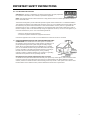
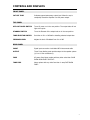
o o o o o o o o o o o o o o o o o o o o o o o o o o o o o o o o o o o o o o o o o o o o o o o o o o o o o o o o o o o o o o o o o o o o o o o o o o o o o o o o o o o o OWNER’S MANUAL o o o o o o o o o o o o o o o o o o o o o o o o o o o o o o o o o o o o o o o o o o o o o o o o o o o o o o o o o o o o o o o o o o o o o o o o o o o o o o o o o o o o CAD-805AE Mono Power Amplifier NOTE: Before installing your new component, please read this manual carefully as it will inform you of the product specifications, proper installation and correct operating procedures for your unit. Also included in this manual are guidelines on how to service and care for your new Cary Audio Design product. TABLE OF CONTENTS Important Safety Instructions ......................................................................................................... 2 Welcome Product Overview ............................................................................................................................. 5 Unpacking and Installation ................................................................................................................ 5 Specifications ................................................................................................................................... 6 Controls and Displays Front Panel ...................................................................................................................................... 7 Top Panel ........................................................................................................................................ 7 Rear Panel ....................................................................................................................................... 7 Operation Physical Placement ........................................................................................................................... 8 Power Requirements......................................................................................................................... 8 Speaker Cables ................................................................................................................................ 8 Interconnect Cables .......................................................................................................................... 8 Off/On Power Toggle Switch ............................................................................................................. 9 Standby Toggle Switch ..................................................................................................................... 9 ‘Break In’ Period ............................................................................................................................... 9 Replacing Vacuum Tubes .................................................................................................................. 9 Service and Care Care and Cleaning .......................................................................................................................... 10 Factory Service .............................................................................................................................. 10 Non-Warranty Repairs .................................................................................................................... 10 Troubleshooting Guide .................................................................................................................... 10 Limited Warranty ........................................................................................................................... 12 IMPORTANT SAFETY INSTRUCTIONS WARNING: To reduce the risk of fire or electric shock, do not expose this appliance to rain or moisture. The lightning flash with arrowhead symbol within an equilateral triangle is intended to alert the user to the presence of un-insulated dangerous voltage within the product’s enclosure that may be of sufficient magnitude to constitute a risk of electric shock to persons. CAUTION: To reduce the risk of electric shock, do not remove the cover. There are no user serviceable parts inside. Please refer to qualified personnel for service. ALERT: The exclamation point within an equilateral triangle is intended to alert the user of the presence of important operating and maintenance (servicing) instructions in the literature accompanying the component. 1. READ ALL INSTRUCTIONS: All the safety and operating instructions of your Cary Audio equipment should be read before power is applied to the equipment. 2. RETAIN OWNER'S MANUAL: These safety and operating instructions should be retained for future reference. 3. HEED WARNING: All warnings on the unit and in the operating instructions should be adhered to. 4. FOLLOW INSTRUCTIONS: All operating and use instructions should be followed. 5. CLEANING: Unplug the unit from the wall outlet before cleaning. The unit should be cleaned only as recommended by the manufacturer. 6. ATTACHMENTS: Do not use attachments not recommended by the unit manufacturer as they may cause hazards. 7. WATER AND MOISTURE: Do not use the unit near water - for example, near a bath tub, wash bowl, kitchen sink, or laundry tub; in a wet basement; or near a swimming pool. 8. ACCESSORIES: Do not place the unit on an unstable cart, stand, tripod, bracket, or table. The unit may fall, causing serious injury to a child, an adult, or damage to the unit. Mounting of the unit should follow the manufacturer's instructions and should use a mounting accessory recommended by the manufacturer. 9. VENTILATION: Slots and openings in the cabinet are provided for ventilation to ensure reliable operation of the unit and to protect it from overheating. These openings must not be blocked or covered. The top or bottom panel openings should never be blocked by placing the unit on a bed, sofa, rug, or other similar surface. The unit should not be installed in a built-in location such as a bookcase or rack unless proper ventilation is provided. There should be free space of at least 6 inches (16cm) above the unit and an opening behind the unit. 10. GROUNDING OR POLARIZATION: The unit may be equipped with a polarized alternating current line plug (a plug having one blade wider than the other). This plug will fit into the power outlet only one way. This is a safety feature. If you cannot insert the plug fully into the outlet, try reversing the plug. If the plug should fail to fit, contact a licensed electrician to replace your obsolete outlet. Do not defeat the safety purpose of the polarized plug. 11. POWER SOURCES: The unit should be operated only from the type of power source indicated on the marking label. If you are not sure of the type of power supplied to your home, consult your unit dealer or local power company. 12. POWER CORD PROTECTION: Power supply cords should be routed so that they are unlikely to be walked on or pinched by items placed on or against them. Pay close attention to cords where they enter a plug, or a convenience receptacle, and the point where they exit from the unit. 13. OUTDOOR ANTENNA GROUNDING: If an outside antenna or cable system is connected to the unit, be sure the antenna or cable system is grounded so as to provide protection against voltage surges and built-up static charges. Article 810 of the National Electrical Code, NSI/NFPA 70, provides information regarding proper grounding of the mast and supporting structure, grounding of the lead-in wire to an Antenna-discharge unit, size of grounding conductors, location of antenna-discharge unit, connection to grounding electrodes, and requirements for the grounding electrode. 2 IMPORTANT SAFETY INSTRUCTIONS 14. LIGHTNING: For added protection for the unit during a lightning storm, or when it is left unattended and unused for long periods of time, unplug it from the wall outlet and disconnect the antenna or cable system. This will prevent damage to the unit due to lightning and power line surges. 15. POWER LINES: An outside antenna system should not be located in the vicinity of overhead power lines or other electric light or power circuits, or where it can fall into such power lines or circuits. When installing an outside antenna system, take extreme care to keep from touching such power lines or circuits as contact with them might be fatal. 16. OVERLOADING: Do not overload wall outlets, extension cords, or integral convenience receptacles as this can result in a risk of fire or electric shock. 17. OBJECT AND LIQUID ENTRY: Never push objects of any kind into the unit through openings as they may touch dangerous voltage points or short-out parts that could result in a fire or electric shock. Never spill liquid of any kind on the unit. 18. SERVICING: Do not attempt to service the unit yourself as opening or removing covers may expose you to dangerous voltage or other hazards. Refer all servicing to qualified service personnel. 19. REPLACEMENT PARTS: When replacement parts are required, be sure the service technician has used replacement parts specified by the manufacturer or have the same characteristics as the original part. Unauthorized substitutions may result in fire, electric shock or other hazards. 20. SAFETY CHECK: Upon completion of any service or repairs to the unit, ask the service technician to perform safety checks to determine that the unit is in proper operating condition. 21. WALL OR CEILING MOUNTING: The unit should be mounted to a wall or ceiling only as recommended by the manufacturer. 22. HEAT: The unit should be situated away from heat sources such as radiators, heat registers, stoves, or other units (including amplifiers) that produce heat. 23. IMPORTANT SAFETY NOTE: Before connecting a new component such as the DVD 7 to your audio or home theater system it is always good practice to make certain that all components are turned off, and preferably unplugged from their AC power source. Many modern electronics products feature automatic turn-on circuits that may be activated during an installation, causing the potential for damage to electronic components and/or speakers. Such damage is not covered by product warranties and Cary Audio specifically disclaims responsibility for any such damage. Power Cord: The removable power cord that is shipped with the player is specifically designed to be used with this product. Other AC cords may be used, so consult your dealer for advice on AC power cords and high quality wire in your system. AC Fuse: The fuse is located inside the chassis and is not user serviceable. If power does not come on, contact your authorized service representative. Wiring: Cables that run inside of walls should have the appropriate markings to indicate compliance with, and listing by the UL, CSA or other standards required by the UL, CSA, NEC or your local building code. Questions about cables inside of walls should be referred to a qualified custom installer, or a licensed electrician or low-voltage contractor. Do Not Open the Cabinet: There are no user serviceable components inside this product. Opening the cabinet may present a shock hazard, and any modification to the product will void your warranty. If water or any metal object, such as a paper clip, coin, or staple accidentally falls inside the unit, disconnect it from the AC power source immediately and contact Cary Audio for further instructions. 24. RECORDING COPYRIGHT: Recording of copyrighted material for other than personal use is illegal without permission of the copyright holder. 25. NOTE TO CATV SYSTEM INSTALLER: This reminder is provided to call the CATV system installer's attention to article 820-40 of the NEC, ANSI/NFPA 70, which provides guidelines for proper grounding and, in particular, specifies that the cable ground shall be connected to the grounding system of the building, as close to the point of cable entry as practical. 3 IMPORTANT SAFETY INSTRUCTIONS 26. FCC INFORMATION FOR USER: CAUTION: ANY changes or modifications not expressly approved by the party responsible for compliance could void the user's authority to operate the equipment. NOTE: This equipment has been tested and found to comply with the limits for a Class B digital device pursuant to Part 15 of the FCC Rules. These limits are designed to provide reasonable protection against harmful interference in a residential installation. This equipment generates and can radiate radio frequency energy and, if not installed and used in accordance with the instructions, may cause harmful interference to radio communications. However, there is no guarantee that interference will not occur in a particular installation. If this equipment does cause harmful interference to radio or television reception, which can be determined by turning the equipment off and on, the user is encouraged to try to correct the interference by one or more of the following measures: - Reorient or relocate the receiving antenna. - Increase the separation between the equipment and receiver. Connect the equipment into an outlet on a circuit different from where the receiver is connected. 27. OUTDOOR ANTENNA INSTALLATION/SAFE ANTENNA AND CABLE CONNECTION: If an outside antenna or cable system is connected to the equipment, be sure the antenna or cable system is grounded so as to provide protection against built up static charges and voltage surges, Section 810 of the national Electrical Code, ANSI/NFP A70 (in Canada, part 1 of the Canadian Electrical Code) provides information with respect to proper grounding of the mast and supporting structure, grounding of the lead-in wire to an antenna discharge unit, size of grounding conductors, location of antenna discharge unit, connection to grounding electrodes and requirements for the grounding electrode. Keep Antenna Clear of High Voltage Power Lines or Circuits An outside antenna system should be located well away from power lines, electric light or power circuits and where it will never come into contact with these power sources if it should happen to fall. When installing an outside antenna, extreme care should be taken to avoid touching power lines, circuits or other power sources as this could be fatal. Because of the hazards involved, antenna installation should be left to a professional. 4 WELCOME PRODUCT OVERVIEW After ten years of continuous production we are proud to offer the CAD 805 Anniversary Edition. Each unit is designed for long term stability in virtually any home operating situation. Note that if the unit is operated outside the parameters outlined in this owner’s manual, damage may result. Please read this manual carefully before operating your new CAD 805 AE power amplifiers. The CAD 805 Anniversary Edition offers 50 watts per channel, Pure Class A Single Ended Triode Mono Blocks with dual 6SN7 input stage, 300B driver stage tube, includes both 845 and 211 output tubes. It offers a user selector switch for the output tube, a Jaguar Anthracite black chassis and top plate with clear coat finish, and an anodized aluminum front panel with a ZERO feedback design. The 805 is a 300SE with an afterburner. The 805 has been through many versions through the years, improving on what already proved to be an outstanding power amplifier. The new design for the Anniversary Edition came about with the goal to take those years of practical field experience, and put everything in the kitchen sink- including the ability to switch from the 211 (output) tube to the 845 (output) tube. UNPACKING AND INSTALLATION This section describes the unpacking and installation procedures for your new component. Unpacking All Cary Audio Design shipping cartons have been specially designed to protect their contents and special care has been taken to prevent damage under normal shipping conditions. Mishandling should be evident upon inspection of the shipping container. If shipping damage is found after visual inspection, take care not to destroy the evidence. If necessary, document the damage with photographs and contact the transport carrier immediately. Carefully remove your new component from its packing carton and examine it closely for signs of shipping damage. We strongly recommend saving all original packing cartons to protect your component from damage should you wish to store it or ship it at a later date. Warranty Card If you are the original purchaser of this unit and you purchased it in the United States, you should fill out the enclosed warranty registration card and return it to Cary Audio Design within 15 days of your purchase. Cary Audio Design also suggests that you keep your original packing cartons in case you ever need to ship the unit when moving to a new home. Warranty restrictions apply. Consult the warranty section of this manual for details. Please be certain to keep a copy of the original sales receipt from your Authorized Cary Audio Design dealer to validate the warranty if ever needed. 5 SPECIFICATIONS Operating the CAD 805 AE’s is a simple procedure, since each unit is designed for long term stability in virtually any home operating situation. However, if the unit is operated outside the parameters outlined in this owner’s manual, damage may result. Please read this manual carefully before putting your new CAD 805 AE in operation. ........................................................................................................................................................................... Power Output 50 Watts ‘Class A’ operation mode ........................................................................................................................................................................... Feedback 0 to 10 dB, continuously variable control ........................................................................................................................................................................... Frequency Response 20 to 20 kHz + 0.5 dB ........................................................................................................................................................................... AC Power Requirements 100, 110, 117, 220, 240, / 50-60 Hz, set by market ........................................................................................................................................................................... Power Consumption 230 watts - OPERATE, 76 watts - STANDBY ........................................................................................................................................................................... Shipping Weight 105 lbs. (47.7 kg.) ........................................................................................................................................................................... Input Impedance 150,000 ohms (150 kg.) ........................................................................................................................................................................... Output Impedance 4, 8 and 16 ohm speaker connection terminals ........................................................................................................................................................................... Noise > 80 dB below rated output ........................................................................................................................................................................... Sensitivity 1.0 Volt @ zero feedback for full output ........................................................................................................................................................................... Coupling Capacitors Oil filled capacitors ........................................................................................................................................................................... Power Supply Capacitors 4 - 1500 Fd @ 450V ........................................................................................................................................................................... Transformers 1 - EI Laminated core power transformer 1 - Special air-gap output transformer 200% duty cycle on all transformers ........................................................................................................................................................................... Tube Compliment In each amplifier chassis 1 2 1 1 1 - 1629/6U5 ‘Cat Eye’ tube 6SN7 input tubes 300B driver tube 845 output tube or (Please choose 845 or 211 during install) 211 output tube (Please choose 211 or 845 during install) ........................................................................................................................................................................... Warm-Up Time 5 minutes, after initial break in period ........................................................................................................................................................................... Break-In Period 100 hours of music playing time ........................................................................................................................................................................... Finish Jaguar ‘Anthracite Black’ chassis ........................................................................................................................................................................... AC Cord 3 conductor cord, detachable ........................................................................................................................................................................... Dimensions 10” H x 12-1/4” W x 24” D (25.4 x 31.2 x 61 cm) ........................................................................................................................................................................... Net Weight 85 lbs. (38.6 kg.) ........................................................................................................................................................................... 6 CONTROLS AND DISPLAYS FRONT PANEL CAT EYE TUBE Indicates approximate power output level. When the eye is completely closed the amplifier is at full power output. TOP PANEL OFF-ON TOGGLE SWITCH Turns AC power on in the rear position. The output tube will not light at this point. STANDBY SWITCH Turns the filament of the output tube on in the rear position. TUBE SELECTOR SWITCH Set either to 211 or 845 before installing selected output tube. FEEDBACK LEVEL Adjusts the level of feedback from 0 to 10 dB REAR PANEL INPUT Signal input connection via shielded RCA interconnect cable OUTPUT Three 5-way binding posts provide output to the speaker system (4, 8 or 16 ohm connections). FUSE AC power fuse. Never replace with any other value than 3 AMP SLOW BLOW FUSE! 250 VOLT! TUBE FUSE Never replace with any other fuse than ¼ amp FAST BLOW FUSE! 7 OPERATION PHYSICAL PLACEMENT The CAD-805 Anniversary Edition is designed for use in homes. It must be protected from the elements and temperature extremes. For example, avoid placing the unit in extremely hot locations such as near radiators or other heating units. Its location among the user’s audio components is not critical; however, certain precautions must be taken. Avoid moisture, direct sunlight, and dusty areas. POWER REQUIREMENTS The CAD-805 Anniversary Edition is designed to operate from house current AC mains. The design voltage is 117 Volts AC at 50/60Hz (Foreign units 234 Volts AC at 50/60Hz). SPEAKER CABLES The speaker cables from the output posts of the CAD-805 Anniversary Edition to the speaker system can be any length that your setup requires. Select speaker cables of sufficient size to preserve the outstanding performance capabilities and sound quality of your new power amplifiers. Heavy duty #14 gauge wire is suitable for distances up to 15 feet; #10 gauge is good for 25-30 feet. Most audio dealers have high performance speaker cable in stock for this purpose. We strongly urge you to try several types to find the best ones for your combination of components and speakers. INTERCONNECT CABLES Signal input connection is made via the RCA input jack on the rear of the amplifier located next to the output binding posts. The input interconnect cables from the output of the preamplifier can be any length your installation requires. A shielded high quality interconnect cable is important to reduce chances for hum or interference. Ask your Authorized Cary Audio Design audio dealer for advice. Operation Your new amplifier is ready for operation after the speaker cables, interconnect cables and the tubes have been installed. Choose either the 211 or the 845 output tube with the top panel tube selector switch, according to the actual one installed. Only change this switch setting with the amplifier OFF. WARNING FAILURE TO INSTALL THE TUBES CORRECTLY WILL DAMAGE THE UNIT. Watch the tube pins carefully on the 300B tube during installation as it is possible to force the tube to plug in ‘wrong’ during installation. The 300B tube has no ‘safety key’ center pin on the tube to prevent incorrect installation. It has two large pins and two slightly smaller pins. Please look carefully at the tube pins and the tube socket holes to note the two different size connections prior to installation. Incorrectly plugging in the 300B driver tube will possibly damage the amplifier and is not covered by the manufacturer’s warranty. 8 OPERATION OFF/ON POWER TOGGLE SWITCH Push the AC toggle switch toward the rear, to the “ON” position. The 6SN7 input tubes, 1629 Cat Eye tube and the 300B driver tube will light up in this setting. STANDBY TOGGLE SWITCH Push the toggle switch toward the rear of the unit to operate. The output tube will light up. ‘BREAK IN’ PERIOD The tubes, capacitors and the output transformers take approximately 100 hours of music playing to fully settle in for peak performance. Small imperfections in the tube surfaces will ‘boil off’ during the break in period as well. The amplifier will sound good right out of the box but it will improve as break in occurs. After the first couple of hours you will notice increased depth and tighter bass. This break in period is true with most high performance audio amplifiers. REPLACING VACUUM TUBES If it becomes necessary to replace the tubes, the same brand as installed new should be used. A complete new tube kit is available from Cary Audio Design. Although useful tube life varies depending on the nature and degree of use, under normal home use, the 845 or the 211 output tube and the 300B driver tube should last many years in the CAD-805. The 6SN7 input tubes should last even longer. NOTE Any current production or New Old Stock (NOS) types of 211, 845, 6SN7 or 300B tubes will work fine in the CAD-805 Anniversary Edition amplifier. The voltages are fine for all available types. WARNING Make sure the amplifier is unplugged 30 minutes from the AC mains before replacing the tubes to avoid risk of shock and high heat from the 211 or 845 tube. 9 SERVICE AND CARE CARE AND CLEANING The cabinet housing and front panel of the CD 306 SACD may be cleaned with a soft cloth and Windex or a window cleaner. The frequency of cleaning will be governed by how many hours the CD 306 SACD is operated and by operating environment cleanliness. FACTORY SERVICE Careful consideration has been given to the design of your CD 306 SACD processor to keep maintenance problems to a minimum. Any problems or requests for service should be referred to our Customer Service Department at 919-355-0010. DO NOT return the CD 306 SACD to the factory without a return authorization number (RA) from the Customer Service Department. Cary Audio Design will assume no responsibility if the shipping company refuses to pay for damage due to your improper packing or lack of insurance should the unit be lost or damaged in shipment. Please retain and always use the original shipping carton for shipping the player. NON-WARRANTY REPAIRS Cary Audio Design will provide repair service for its products charging on a time and expense basis. At this time, the standard non warranty service bench fee is $125 with all parts used for repair charged extra. This may change and is not a quote for service. Please call us at 919-3550010 for more information about out of warranty service and repair fees. CAUTION Never remove or insert the back panel AC plug when the unit is on or the ac cord is plugged into the wall. TROUBLESHOOTING GUIDE SYMPTOM CAUSE REMEDY Hum or “Buzzing” in speakers Ground loop Install 2-pin adapter on AC cord to float the ground “Popping” or “Spitting” noise 300B tube with high plate current too high Check bias of 300B. If high, readjust to proper bias setting of 60 mA Intermittent or poor connection of interconnect Replace bad interconnect cable Noisy tube If noise is in one channel through the speaker, swap one section of tubes at a time until the noise swaps channels. Replace the noisy tube. Check bias of output tubes If high or fluctuating rapidly, 10 SERVICE AND CARE replace output tube AC fuse blows Line voltage surge Replace fuse Tube fuse blows Shorted tube (300B & 845 have separate fuses.) Replace tube 11 LIMITED WARRANTY Cary Audio Warrants to the original United States purchaser for use in the United States the Following Cary Audio Products for the Periods Indicated: 1. Power Amplifiers, Integrated Amplifiers, Surround Sound Processors, and Preamplifiers have a three (3) year parts and labor warranty from the date of the original purchase from Cary Audio. 2. CD or SACD players, DVD players, or Music Servers have an eighteen (18) month parts and labor warranty from the date of the original purchase from Cary Audio. 3. Vacuum tubes, if any are used in the component, are offered a 90-day exchange policy against defects with the exception of the CAVT 300B vacuum tube that has a one (1) year exchange policy from the date of the original purchase from Cary Audio. What is Covered and What is Not Covered Except as specified below, this warranty covers parts and labor to correct all defects in materials and workmanship. The following are not covered by the warranty: 1. Damage, deterioration, malfunction or failure to meet performance specifications resulting from: a. Accident, acts of nature, misuse, abuse, neglect or unauthorized product modifications b. Improper installation, removal or maintenance, or failure to follow instructions supplied with the product. c. Repair or attempted repair by anyone not authorized by Cary Audio to repair the product. d. Any shipment of the product (claims must be presented to the carrier). e. Any cause other than a product defect. 2. Cleaning, initial set-up, check-ups with no defects found, or charges incurred for installation, removal or reinstallation of the product. 3. Any product, on which the serial number has been defaced, modified or removed. 4. Batteries. 5. Accessories, including but not limited to, batteries, cables, mounting hardware and brackets, cleaning accessories, antenna and detachable power cords. 6. Warranty is void if purchase was made from anyone other than an authorized Cary Audio dealer. Who May Enforce the Warranty? This warranty extends to products purchased directly from Cary Audio or an authorized Cary Audio dealer. Purchasers should inquire of the dealer regarding the nature and extent of the dealer’s warranty, if any. 12 LIMITED WARRANTY To obtain such warranty service, the original purchaser must complete and send in the Warranty Registration Card within 15 days of purchase. What Will We Pay For? We will pay for all labor and material expenses for items covered by the warranty. Payment of shipping charges is discussed in the next section of this warranty. How You Can Get Service? In the event that the owner needs to return the unit to Cary Audio for service or repair of a possible defect, he must follow the following steps: 1. Contact Cary Audio at 919-355-0010 to obtain a Return Merchandise Authorization (RMA) number prior to shipping; include this number with the package 2. Submit a copy of the original sales receipt; blank receipts will not validate the limited warranty for service by Cary Audio. The original sales receipt must contain the following information: a. The authorized Cary Audio dealer’s name b. The date of purchase c. The unit’s sales price d. The buyer’s name and address e. Describe in detail the problem. f. Note the unit’s model number and serial number. 3. Deliver by either of these methods: a. With all freight and insurance charges prepaid and in its original packing container or equivalent, ship the component to Cary Audio, 1020 Goodworth Drive Apex, NC 27539. b. Hand-deliver the product to Cary Audio (address noted above) or the nearest authorized service facility. Limitation of Implied Warranties All implied warranties, including warranties of merchantability and fitness for particular purchase, are limited in duration to the length of this warranty. Exclusion of Damages Cary Audio’s liability for any defective product is limited to repair or replacement of the product at Cary Audio’s option. Cary Audio shall not be liable for damage to other products caused by any defects in Cary Audio products, damages based upon inconvenience or loss of use of the product, or any other damages, whether incidental, consequential, or otherwise. 13 LIMITED WARRANTY How State Law Relates to the Warranty Some states do not allow limitations on how long an implied warranty lasts and/or do not allow the exclusion or limitation of incidental or consequential damages, so the above limitations or exclusions may not apply to you. This warranty gives you specific legal rights, and you may also have other rights which vary from state to state. International Purchasers (Export Markets) Cary Audio warrants its merchandise to purchasers within the United States exclusively for use within the United States. It provides no other warranties, expressed or implied. If you are living outside of the United States, please consult your local dealer or distributor to determine the details of your local warranty. 14 1020 Goodworth Drive, Apex, NC 27539 phone 919-355-0010 fax 919-355-0013 www.caryaudio.com o o o o o o o o o o o o o o o o o o o o o o o o o CARY AUDIO DESIGN o o o o o o o o o o o o o o o o o o o o o o o o o o o o o o o o o o o o o o o o o o o o o o o o o o o o o o o o o o o o o o o o o o o o o o o o o o o o o o o o o o o o o