1
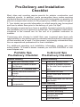
Contents
Pre-Delivery and Installation Checklist................................................. 1
Portable Spa Site Preparation................................................................ 4
In-Ground Spa Site Preparation............................................................. 4
Getting the Spa Into Your Yard............................................................... 6
Electrical Requirements......................................................................... 8
Electrical Requirements – US and Canada....................................................... 8
Electrical Installation -- Europe....................................................................... 13
Installing the In-Ground Shell.............................................................. 16
Equipment Pack Plumbing Connections (In-Ground Spas).............. 17
Plumbing Connections..................................................................................... 19
Electrical and Electronic Connection............................................................... 21
Pouring the Deck............................................................................................. 25
Spa Technical Specifications............................................................... 26
CONTACT INFORMATION
Copyright 2008 Lloyds Material Supply,
Inc. All rights reserved. Duplication without written consent is strictly prohibited.
Cal Spas® is a registered trademark.
Due to continuous improvement programs, all models, operation, and/or
specifications are subject to change without prior notice.
LTR20081024, Rev. B
6/12/08
For customer service, please contact
your authorized dealer immediately. If
you need additional information and/or
assistance, please contact:
L.M.S. Customer Service Department
1462 East Ninth Street
Pomona, CA 91766
Toll Free: 1-800-CAL-SPAS
Fax: 1-909-629-3890
www.calspas.com
Pre-Delivery and Installation
Checklist
Most cities and counties require permits for exterior construction and
electrical circuits. In addition, some communities have codes requiring
residential barriers such as fencing and/or self-closing gates on property to
prevent unsupervised access to the property by children under the age of
5. Your dealer can provide information on which permits may be required
and how to obtain them prior to the delivery of your Cal Spa®.
We strongly recommend you have a qualified, licensed contractor perform
the installation of your in-ground or ported spa. The installation instructions
contained in the manual are for the use of a qualified contractor or
installer.
Consumers who choose to install their own in-ground spas bear sole
responsibility for any performance or warranty issues and may void portions
of their warranty as a result. For this reason, we strongly recommend they
hire an experienced professional for their installation.
For additional operating and installation information, please see your
selling dealer. To locate a dealer nearest you call 800-CALSPAS or visit
www.calspas.com.
Portable Spa
Pre-Delivery Checklist
In-Ground Spa
Pre-Delivery Checklist
Before Delivery
Before Delivery
Plan your delivery route
Plan your delivery route
Choose a suitable location
for the spa
Choose a suitable location
for the shell and equipment
pack
Lay a 3” - 4” concrete slab
Install dedicated electrical
supply
After Delivery
Place spa on slab
Connect electrical
components
Excavate the hole
Install dedicated electrical
supply
Install dedicated NG line for
gas heater
After Delivery
Install shell in ground
Install equipment pack
Connect plumbing
Connect electrical
components
Pour the deck
1
Planning the Best Location
Safety first
Do not place your spa within 10 feet (3 m) of overhead power lines.
Make sure the spa is positioned so that access to the equipment
compartment and all side panels will not be blocked. Be certain that your
installation will meet all city and local safety codes and requirements.
Consider how you will use your spa
How you intend to use your spa will help you determine where you should
position it. For example, will you use your spa for recreational or therapeutic
purposes? If your spa is mainly used for family recreation, be sure to leave
plenty of room around it for activity. If you will use it for relaxation and
therapy, you’ll probably want to create a specific mood around it.
Plan for your environment
If you live in a region where it snows in the winter or rains frequently, place
the spa near a house entry. By doing this, you will have a place to change
clothes and not be uncomfortable.
Consider your privacy
In a cold-weather climate, bare trees won’t provide much privacy. Think of
your spa’s surroundings during all seasons to determine your best privacy
options. Consider the view of your neighbors as well when you plan the
location of your spa.
Provide a view with your spa
Think about the direction you will be facing when sitting in your spa. Do
you have a special landscaped area in your yard that you find enjoyable?
Perhaps there is an area that catches a soothing breeze during the day or
a lovely sunset in the evening.
Keep your spa clean
Prevent dirt and contaminants from being tracked into your spa by placing
a foot mat at the spa’s entrance where the bather’s can clean their feet
before entering your spa. You may also consider keeping a small waterfilled basin nearby for bathers to rinse their feet before entering your spa.
In planning your spa’s location, consider a location where the path to and
from the house can be kept clean and free of debris.
2
Allow for service access
Many people choose to install a decorative structure around their spa. If
you are installing your spa with any type of structure on the outside, such
as a gazebo, remember to allow access for service. It is always best to
design special installations so that the spa can still be accessed.
Consider the best place for the outdoor equipment pack
(in-ground spas only)
The Designer Spa series requires an external equipment pack. When
locating the outdoor equipment pack, you will want to consider the
following:
•
The equipment pack must be located within a maximum of 15 feet
from the spa.
•
Ensure the equipment running its normal filtration cycles does not
make too much noise for spa owners and/or neighbors.
•
Ensure the equipment can be easily serviced for filter cleaning and
periodic inspections in the location chosen.
•
If you are using a gas heater, you will need to consider wind and drafts
as well as heater exhaust for proper heater placement. (See heater
owner’s manual for important location and safety information.)
•
The equipment base and heater must be placed on either a 3 1/2”
cement slab or 3” paving stones.
•
Make sure the equipment area selected will not be in an area where
water could run or stand.
•
If the area receives direct sunlight, you will want to provide some
protection for the equipment portion of the equipment pack.
The equipment pack and heater are delivered separately. Do not cover gas
heaters unless properly vented. (See heater owner’s manual for important
safety information.)
3
Portable Spa Site Preparation
Your spa needs a solid and level foundation. The area that it sits on must
be able to support the weight of the spa, with water and the occupants who
use it. If the foundation is inadequate, it may shift or settle after the spa
is in place, causing stress that could DAMAGE YOUR SPA SHELL AND
FINISH.
Note: Damage caused by inadequate or improper foundation support is
not covered by the warranty. It is the responsibility of the spa owner to
provide a proper foundation for the spa.
Place the spa on an elevated foundation (preferably a 3” - 4” concrete
slab). Pavers, gravel, brick, sand, timbers or dirt foundations are not
adequate to support the spa. If you are installing the spa indoors, pay
close attention to the flooring beneath it. Choose flooring that will not be
damaged or stained.
If you are installing your spa on an elevated wood deck or other structure, it
is highly recommended that you consult a structural engineer or contractor
to ensure the structure will support the weight of 150 pounds per square
foot.
To properly identify the weight of your new spa when full, remember water
weighs 8.33 lbs. per gallon. For example, an average 8’ spa spa holds
approximately 500 gallons of water. Using this formula, you will find that
the weight of the water alone is 4,165 lbs. Combined with the dry weight
of the spa you will note that this spa will weigh approximately 5,000 lbs.
when full of water.
Note: It is strongly recommended that a qualified, licensed contractor
prepare the foundation for your spa.
Your Cal Spas® retailer can help you with your foundation and more. Your
retailer has a wealth of information and experience about how to get the
most out of your spa and can provide you with a full line of accessories
that are designed to complement your spa and increase your enjoyment.
In-Ground Spa Site Preparation
•
Ensure there is enough room for the spa and equipment.
•
The equipment pack must be located within a maximum of 15 feet
from the spa.
•
Plan for proper electrical and gas service to both the equipment area
and spa side.
•
Ensure the required flat, level foundation can be constructed in the
area chosen.
4
•
The spa must be properly back-filled with wet sand, underneath and
on all four sides.
•
The final architecture must include permanent ground coverage within
a 10 feet radius of the spa.
•
Never place any spa in a sealed area. Water must be able either to be
absorbed into the surrounding area or channeled away. Water buildup under and/or around the spa, will cause the spa to float out of the
ground.
Grading Prior to Excavation
Selection of the Designer Spas site will determine how much grading will
have to be accomplished prior to the actual dig for the spa. Naturally, a
level area is best because it will require the least amount of preparation for
the dig, but in many cases there is no level area, therefore, the site must
be prepared to accept the Spa prior to dig. The spa site should be elevated
slightly higher than the surrounding area
When dealing with slopes, the severity of the slope will determine if
retaining walls must be built in order to have a level area for the spa. If the
slope is relatively minor, contact your local building safety.
Site Excavation – Hard Bottom
For hard bottom placement for in-ground spas, you will need a smooth and
flat concrete surface at least 4” thick as large as the bottom contact points.
Be sure not to seal the bottom off and making a sealed box. You will need
adequate water drainage for escape under the spa. A gravel beds around
the concrete base will help with this.
Site Excavation – Sand Bottom
With the spa area and all elevations planned including your decided type
of decking, you are now ready to proceed with the dig. An ideal excavation
is one that is as close as possible to the dimensions of the spa shell, but
with the following rules in mind. The excavation should be 2” to 4” deeper
than the actual spa for your sand bed. The sand bed is to level the spa
shell and provide a perfect support base with no voids when the spa is
lowered into the hole. Your excavation should be approximately one foot
longer and one foot wider than the spa shell. This will allow for a six inch
over dig all the way around the spa once it is in place. Additional hand
excavation will be required to insure the skimmer will fit in the excavation
when attached to the spa.
Sand or rock dust must be used to bed the shell into the excavation and
for backfill. In no event is dirt to be used. One of the easiest ways to know
how much sand is needed to be placed on the bottom of the excavation is
to set a grade stake at all four corners, and one on each side of the center
line in the bottom of the hole. If there are areas that are deeper than 2” to
4”, these can be filled with sand and are of no consequence.
5
Getting the Spa Into Your Yard
Check the Dimensions of Your New Cal Spa®
The Cal Spas® specification chart lists your spa’s model and its dimension
as it sits on the delivery cart. During delivery, the spa must remain on the
delivery cart at all times. Compare the dimensions to the width of the gates,
sidewalks, and doorways along the delivery route. It may be necessary for
you to remove a gate or partially remove a fence in order to provide an
unobstructed passageway to the installation location.
Plan the Delivery Route
Consider the following when planning your delivery route:
•
Check the width of gates, doors and sidewalks to make sure your spa
will pass through unobstructed. You may have to remove a gate or
part of a fence to allow for adequate width clearance.
•
Are there low roof eaves, overhanging branches or rain gutters that
could be an obstruction to overhead clearance?
•
8’ spas need at least 42” wide gate and 9’ height clearance.
•
If the delivery route will require a 90º turn, check the measurements at
the turn to ensure the spa will fit.
6
•
Are there protruding gas meters, water meters or A/C units on your
home which will cause obstructions along the delivery path to your
yard?
•
Are there stairs in your delivery route? If so, you must consult your Cal
Spas® dealer prior to delivery to make adequate preparations.
Special Circumstances
The use of a crane for delivery and installation may become necessary if
you are unable to provide an adequate delivery route. It is used primarily
to avoid injury to your spa, your property or to delivery personnel. Your Cal
Spas® dealer may be able to assist you with the arrangements. If your spa
delivery requires the use of a crane, the cost of a crane is generally not
included in the standard delivery service.
7
Electrical Requirements
Electrical Requirements – US and Canada
240 Volt Electrical Installation
All 240V spas must be permanently connected (hardwired) to the power
supply. These instructions describe the only acceptable electrical wiring
procedure. Spas wired in any other way will void your warranty and may
result in serious injury.
This is the only acceptable electrical wiring procedure. Spas wired in any
other way will void your warranty. See the wiring diagram on page 9.
When installed in the United States, the electrical wiring of this spa must
meet the requirements of National Electric Code, ANSI/NFPA 70-2008 and
any applicable local, state, and federal codes. The electrical circuit must
be installed by an electrical contractor and approved by a local building /
electrical inspector.
GFCI and Wiring Requirements
The power supplied to the spa must be on a dedicated GFCI protected
circuit as required by ANSI/NFPA 70 with no other appliances or lights
sharing the power.
Use copper wire with THHN insulation. Do not use aluminum wire.
Use the table on the next page to determine your GFCI and wiring
requirements.
When NEC requires the use of wires larger than #6 AWG, install a junction
box near the spa and use #6 AWG wire between the junction box and the
spa.
Wire runs over 85 feet must increase wire gauge to the next lower number.
For example: A normal 50 amp GFCI
with four #8 AWG Copper wires run
over 85 feet would require you to go to
four #6 AWG copper wires.
Read
and
follow
the
heater
manufacturer’s safety and installation
instructions prior to installation and
operation. Incorrect installation may
damage the heater and void its
warranty.
8
Portable Spas
Spa Model
All 240V spas (except
6300 control boxes
requiring high amperage
- see below)
GFCI Required
Wires Required
One 50 amp GFCI
Four #8 AWG copper
wires
One 60 amp GFCI
Spas with the 6300
control box (when high
amperage is selected on
circuit board)
Four #8 AWG copper
wires
SEE CONFIGURATION
INSTRUCTIONS ON
NEXT PAGE.
In-Ground Spas
Ultimate Fitness Spas
Fitness spa with 5.5 kW
heater
Fitness spa with two 11
kW heater and Fitness
Pro 2500 spa
Fitness Pro 4700 spa
One 50 amp GFCI
Four #8 AWG copper
wires
Service 1: One 50
amp GFCI
Service 1: Four #8
AWG copper wires
Service 2: One 30
amp GFCI
Service 2: Three #8
AWG copper wires
Service 1 (swim
side): One 60 amp
GFCI
Service 1: Four #8
AWG copper wires
Service 2 (swim
side): One 30 amp
GFCI
Service 2: Three #8
AWG copper wires
Service 3 (spa
side): One 40 amp
GFCI
Service 3: Four #8
AWG copper wires
Designer in-ground spas One 50 amp GFCI
with one 5.5 kW heater
Designer in-ground spa
with two 5.5 kW heaters
Designer in-ground spa
with gas heater
Four #8 AWG copper
wires
Service 1: One 50
amp GFCI
Service 1: Four #8
AWG copper wires
Service 2: One 30
amp GFCI
Service 2: Three #8
AWG copper wires
One 50 amp GFCI
Four #8 AWG copper
wires
9
Testing the GFCI Breaker
Test the GFCI breaker prior to
first use and periodically when the
spa is powered. To test the GFCI
breaker follow these instructions
(spa should be operating):
1. Press the TEST button on the
GFCI. The GFCI will trip and
the spa will shut off.
2. Reset the GFCI breaker by
switching the breaker to the full
OFF position, wait a moment,
then turn the breaker back on.
The spa should have power
again.
Configuring the 6300
Control System
The 6300 control system requires
higher power than other 240V systems. Dip switch #10 is factory set
in the ON position. This causes the
heater to shut off when any pump
is running in high speed. To allow
the heater to continue operating,
dip switch #10 must be set to the
OFF position.
To ensure your spa functions properly, ensure the following steps are
performed before starting your spa:
• When installing the electrical
system, use a 60 amp GFCI.
Follow the GFCI wiring diagram
on the next page.
•
10
Have your dealer or installer
set dip switch #10 to the OFF
position on the circuit board as
shown below.
GFCI Wiring Diagram
11
120 Volt Electrical Installation
Always follow applicable local, state and federal
codes and guidelines.
Use only a dedicated electrical line with a 20-amp
breaker.
Cord-and-plug connections may not use a cord
longer than 15 ft (4.6 m) and must be plugged into
a dedicated 20-amp GFCI connection. Do not use
extension cords!
Always use a weatherproof-covered receptacle.
Receptacle shall be located not less than 5 ft (1.5 m)
from and not exceeding 10 ft (3.0 m) from the inside wall of the spa.
Do not bury the power cord.
If your cord becomes damaged, replace it before next usage.
All 120V spas must have a GFCI. This can be either a 20-amp GFCI
receptacle or a GFCI cord and plug kit as shown at right (CKIT110 - P/N
ELE09700086).
Testing the GFCI Breaker
Test the GFCI plug prior to first use and periodically when the spa is
powered. To test the GFCI plug version, follow these instructions. (Spa
should already be plugged in and operational.)
1. Press the TEST button on the GFCI. The GFCI will trip and the spa will
stop operating.
2. Press the RESET button on the GFCI. The GFCI will reset and the spa
will turn back on.
The spa is now safe to use.
If the GFCI trips while the spa is in use, press the RESET button. If the
GFCI does not reset, unplug the spa and call your local Cal Spas® dealer
for service. DO NOT USE THE SPA!
12
Electrical Installation -- Europe
230 Volt Electrical Installation
All 230V spas must be permanently connected (hardwired) to the power
supply. These instructions describe the only acceptable electrical wiring
procedure. Spas wired in any other way will void your warranty and may
result in serious injury.
This is the only acceptable electrical wiring procedure. Spas wired in any
other way will void your warranty. See the wiring diagram on page 13.
The electrical wiring of this spa must meet the requirements of any applicable
local, state, and federal codes. The electrical circuit
must be installed by an electrical contractor and
approved by a local building / electrical inspector.
RCD and Wiring Requirements
The power supplied to the spa must be on a dedicated
RCD protected circuit with no other appliances or
lights sharing the power.
Use copper wire with THHN insulation. Do not use
aluminum wire.
Use the table on the next page to determine your
GFCI and wiring requirements.
When wires larger than #6 AWG are required, install a junction box near
the spa and use #6 AWG wire between the junction box and the spa.
Wire runs over 85 feet must increase wire gauge to the next lower number.
For example: A normal 50 amp RCD with four #8 AWG copper wires run
over 85 feet would require you to go to four #6 AWG copper wires.
13
Portable Spas
Spa Model
All 230V spas (except
6205 control boxes
requiring high amperage
- see below)
GFCI Required
Wires Required
One 32 amp RCD
or two 16 amp
RCDs
Four #10 AWG
copper wires
One 32 amp RCD
Spas with the 6300
or two 16 amp
control box (when high
amperage is selected on RCDs
circuit board)
Four #10 AWG
copper wires
In-Ground Spas
Ultimate Fitness Spas
SEE CONFIGURATION
INSTRUCTIONS ON
NEXT PAGE.
Ultimate Fitness spas
with one 5.5 kW heater
Ultimate Fitness spas
with two 5.5 kW heaters
One 32 amp RCD
or two 16 amp
RCDs
Four #10 AWG
copper wires
Service 1: One 32
amp RCD or two 16
amp RCDs
Service 1: Four #10
AWG copper wires
Service 2: One 32
amp RCD or two 16
amp RCDs
Service 2: Three #10
AWG copper wires
Designer in-ground spas One 32 amp RCD
with one 3 kW heater
or two 16 amp
RCDs
Designer in-ground spa
with one 3 kW heater
and one 5.5 kW heater
Four #10 AWG
copper wires
Service 1: One 32
amp RCD or two 16
amp RCDs
Service 1: Four #10
AWG copper wires
Service 2: One 32
amp RCD or two 16
amp RCDs
Service 2: Three #10
AWG copper wires
Testing the RCD Breaker
Test the RCD breaker prior to first use and periodically when the spa is
powered. To test the RCD breaker follow these instructions (spa should
be operating):
1. Press the TEST button on the RCD. The RCD will trip and the spa will
shut off.
2. Reset the RCD breaker by switching the breaker to the full OFF position,
wait a moment, then turn the breaker back on. The spa should have
power again.
14
RCD Wiring Diagram
15
Installing the In-Ground Shell
16
Equipment Pack Plumbing
Connections (In-Ground Spas)
The example shown below is typical for a system with two pumps with
external heater and external filter.
Designer Spa Specifications
DIJ401 – DIJ406:
Equipment pack weight = 250 lbs.
DIJ407:
Equipment pack weight = 300 lbs.
2.5 HP heat pump
4 HP swim pump
Note:
Equipment pack cannot exceed
15 feet from spa.
17
18
Plumbing Connections
IMPORTANT! Always check local codes prior to any in-ground spa
installation.
Once the spa and equipment are properly located, you will want to lay out
the plumbing run.
Trenches should be deep and wide enough to allow all pipes to be buried
below the frost line and should be in as straight a line from the spa to the
equipment as possible. Check local code requirements for underground
pipes. Always know what is under the ground before you dig anywhere.
You will need 2” flex or PVC lines for your suction, intake, and air line. In
ground spas have marked intake and suction lines, making it easy find and
connect to and from the spa and equipment pack.
The plumbing run should not be any longer than 15 feet to maximize
water pressure. Another way to maximize water pressure is to limit (or
even eliminate) the use of 90˚ elbows in your plumbing run. A more direct
plumbing run using 45˚ elbows is more efficient, and promotes increased
water pressure.
Identifying Plumbing Lines
The spa’s plumbing lines are clearly marked during water testing at the
factory. This is done to assist installers in properly identifying the installation.
We still recommend that the installers verify plumbing lines prior to gluing.
This can be done by using one of the following techniques.
Air Test
The air test requires a wet/dry vacuum. Locate the plumbing line you
wish to identify and secure the vacuum hose to cut open end. Turn on the
vacuum, enter the spa and listen for vacuum suction sound from inside the
spa side filter canister. If you hear the suction sound in the canister, the
line is properly marked and can be connected to the suction side of the
pump on the equipment pack.
Water Test
The water test requires a garden hose and water source. Locate the
plumbing line you wish to identify and secure the outlet side of the garden
hose to cut open end. Turn on the water supply to the garden hose, enter
the spa and look for water inside the spa side filter canister. If you see
water in the canister the line is properly marked and can be connected to
the suction side of the pump on the equipment pack.
If any plumbing line is not properly marked or not marked at all, follow
either the air or water test procedure until all lines are identified prior to
gluing.
19
NOTE: Once complete, water test the plumbing run for at least three
days prior to covering any plumbing trenches and back-filling spa cavity
completely.
NOTE: Some local inspectors require pressure testing the plumbing lines.
Although the spa is pressure tested at the factory, local inspectors may
insist on pressure testing the plumbing run between the spa and equipment
pack.
Gate/Slice Valves
The use of gate valves is recommended on all plumbing lines (both suction
and return lines). These valves are used to contain the spa’s water in either
the equipment or the spa. This will assist in the pump priming process and
future servicing without needing to drain the spa.
NOTE: When draining the spa to perform maintenance, always close the
gate valves prior to draining. This will maintain the pumps prime.
Connecting Plumbing to Remote Equipment
Connecting the plumbing from the spa to the equipment pack must be
performed in accordance to local and city codes.
NOTE: Most codes require plumbing to be rigid PVC schedule 40 or heavier
in both above and below ground installations. In most cases, the use of
flexible PVC plumbing is acceptable when properly buried in trenches.
Most water plumbing lines are 2” or larger and must be schedule 40 or
heavier PVC. When plumbing, minimize the use of 90˚ elbows as much as
possible. The use of 45 ˚ elbows will increase the amount of jet pressure
you will have over the use of 90˚ elbows.
The plumbing on the spa shell is labeled by the factory in the following
manner:
Pump 1 Suction: 2” line that connects the spa filter and bottom drain
assembly to the front of pump 1.
Pump 1 Return: 2” line that connects the top of pump 1, through the
equipment filter and heater back to selected jets in the spa.
Pump 2 Suction: 2” line that connects the spa filter and bottom drain
assembly to the front of pump 2.
Pump 2 Return: 2” line that connects the top of pump 2 back to selected
jets in the spa.
Ozone Line: 1” line that connects to a 1” flexible line extending off the
bottom of the equipment pack filter canister through an ozone injector (If
ozone equipped) and connected to ozone port on the spa.
Air Blower: 1 1/2” line that is plumbed out of the air blower (located on
the equipment pack) and extended up 18” above the spas water level to
prevent water flooding the air blower.
20
Air Venturi: 1/2” line that is plumbed 18” above the spa’s water level.
Topside Control Panel and Temp Sensor: 1” line that connects to the
bottom of the control box located on the equipment pack.
Electrical and Electronic Connection
Remote Equipment Topside Control Panel
The next few steps to complete the installation should be performed
along with installation of the temperature sensor and 12V spa light wiring
(if applicable). All of these components are generally installed using the
same conduit.
1. Locate the topside control
panel extension loom in the
control box mounted with the
equipment pack. This extension
loom and attached black
terminal connector (see figure
at right) will be used to connect
the topside control panel to the
control box.
2. Connect one end of the black
terminal connector to the topside
control panel cable.
3. Connect the other end of the terminal connector to the extension
loom.
NOTE: This connection must be kept dry. We recommend that a waterproof
junction box be used in installations where moisture could penetrate this
terminal connector.
4. Lay out the extension loom to verify that you have enough length to
reach the control box. Remember that conduit runs are not generally
run in a straight line. Every bend, and up and down run consumes
line length. Take this into consideration when verifying electrical and
plumbing runs.
5. Connect the extension loom to the control panel location on the circuit
board located inside the control box. You will also need to connect
both the temperature and high limit sensors to the circuit board prior to
testing. (See the temperature and high limit installation instruction on
the next page for proper identification and see the wiring diagram on
the inside cover of the control box for proper placement.)
6. Turn on the power supply to the spa equipment and briefly test all
functions on the topside control panel to verify that both connections
and extension loom are in working order before proceeding with the
installation.
21
NOTE: Circuit board programming will not allow spa operation without
both the temperature and high limit sensors being properly connected to
the circuit board.
7. Once topside panel operation is verified. Turn off power, disconnect
the extension loom from the circuit board and GENTLY route through
conduit to complete installation.
NOTE: This loom and its connector are not meant to withstand heavy
pulling. Make sure, when routing the extension loom and temperature
sensor lines through conduit, you exercise extreme caution.
Once properly run through the conduit, repeat steps 5 and 6 above.
In-Ground Spa Light Installation Instructions
On spas ordered with in-ground lights, the factory installs the light niche
for you. The next steps of installation should be performed by a qualified
licensed electrician.
Always read and follow light manufacturer’s safety and installation
instructions prior to installation and operation. Incorrect installation may
damage the light and void its warranty.
The light circuit must be on a GFCI protected service (alone or with a
switch).
The water resistant junction box (or for 12 volt models, the low voltage
transformer) must be located:
•
at least 8” (20 cm) above water level
•
at least 4” (10 cm) above ground level, and
•
at least 48” (121 cm) away from the spa.
See figure below.
22
Light niche and any metallic items in a 5’ (152 cm) radius must be properly
bonded with #8 AWG grounding wire.
1. Connect rigid conduit to the 3/4” hub located at the back of the light
niche and run to a water resistant junction box (or for 12 volt models
to a low voltage transformer) no further than 25’ (7.6m). Remember
this is a water cooled light, so the conduit and all connections must be
leakproof.
2. Feed the light cord through the rigid conduit to the junction box, leaving
at least 4 feet of cord at the end of the light fixture. This slack in the
light cord will allow servicing without draining the spa in the future.
3. Wrap light cord slack around back of light housing and attach light to
niche with mounting screw.
4. Cut the cord at the junction box, leaving at least 6” (15 cm) of cord to
make connections.
5. Strip 6” (15 cm) of the out cord jacket to expose the three insulated
wires. Be careful not to damage the insulation on the three inner
wires.
6. Connect the three wires to the corresponding circuit wires in the
junction box and secure the junction box cover in place.
7. Replace the light assembly in the niche and tighten the special pilot
screw.
8. Fill the spa until the underwater light is completely submerged in water
before operating the light for more than 10 seconds. Turn on the main
switch or circuit breaker, as well as the spa light control, to check for
proper operation
Important: Make sure spa light is submerged in at least 18” of water
prior to testing.
23
24
Pouring the Deck
It is recommended that all electrical hook ups and all plumbing be completed
before pouring the concrete. Make certain all electrical inspections on
lights, bonding and all other electrical work have been completed and
checked off by the local inspectors prior to proceeding with your concrete
or finish work. It is a good idea to run the spa for at least 24 hours before
pouring the concrete to insure there are no leaks. We understand you
want to enjoy your spa now, but a 24-hour period with your spa running will
let you know of any problems before they will be extremely hard to fix.
The type of decking you have selected will have determined the grade of
the spa. If you are pouring a regular deck up to the spas coping, then the
top of the coping should be 4” above the surrounding area. In either event,
it is recommended to dig out an area around the spa exposing the flange
of the coping and just under it. This is important, as concrete should be
packed under and over the flange of the spa, as the deck is poured. This
will lock the spa into the concrete and provide for a much stronger bond
of the spa to the deck. It will also eliminate cracking of the deck where it
meets the spa.
When setting your outside forms, remember you want any water from rain
or splash out to run off the deck, not into the spa. If your deck is going to tie
into an existing deck, than some type of drain system should be planned to
handle the run off. Proper drainage planning is very important.
An experienced concrete finisher should always be used when pouring
spa decks, especially when you are doing a cantilevered deck, as the
forms must be taken off at the proper time to allow finishing of the inside
of the form.
25
Spa Technical Specifications
All sizes on this chart represent top-rail dimensions. Due to our continuous
improvements, specifications, size and pricing are subject to change
without prior notice.
Avalon Series
Model
A726B
Width
Length
Depth
Gallons
Dry
Weight
Filled
Weight
84”
84”
39 1/2”
425
850 Lbs.
4390 Lbs.
A726L
84”
84”
39 1/2”
425
850 Lbs.
4390 Lbs.
A744B
84”
84”
39 1/2”
425
850 Lbs.
4390 Lbs.
A744L
84”
84”
39 1/2”
425
850 Lbs.
4390 Lbs.
A826B
93”
93”
39 1/2”
450
900 Lbs.
4648 Lbs.
A826L
93”
93”
39 1/2”
450
900 Lbs.
4648 Lbs.
A844B
93”
93”
39 1/2”
450
900 Lbs.
4648 Lbs.
A844L
93”
93”
39 1/2”
450
900 Lbs.
4648 Lbs.
A857B
93”
93”
39 1/2”
450
900 Lbs.
4648 Lbs.
A857L
93”
93”
39 1/2”
450
900 Lbs.
4648 Lbs.
A969L
93”
130”
39 1/2”
800
1200 Lbs.
7864 Lbs.
Length
Depth
Gallons
Dry
Weight
Filled
Weight
Designer Series
Model
Width
DI-401
93”
34”
500
500 Lbs.
4665 Lbs.
DI-402
93”
93”
32”
500
500 Lbs.
4665 Lbs.
DI-403
93”
93”
34”
500
500 Lbs.
4665 Lbs.
DI-404
130”
93”
36”
750
750 Lbs.
6997 Lbs.
DI-405
130”
93”
32”
900
750 Lbs.
8247 Lbs.
DI-406
120”
80”
34”
800
750 Lbs.
7414 Lbs.
DI-407
93”
200”
52”
2500
1300 Lbs.
22125 Lbs.
Width
Length
Depth
Family Fun Series
Model
Gallons
Dry
Weight
Filled
Weight
FF-519R
78”
Round
36”
125
350
1390
FF730B
84”
84”
39-1/2”
425
800
4340
FF830L
93”
93”
39-1/2”
450
900
4650
26
Classic and Legacy Series
Width
Length
Depth
Gallons
Dry
Weight
Filled
Weight
CL-24
LL-24
64”
84”
32”
125
535 Lbs.
1576 Lbs.
CP-34
LP-34
84”
84”
39 1/2”
425
850 Lbs.
4390 Lbs.
CT-34
LT-34
84”
84”
39 1/2”
425
850 Lbs.
4390 Lbs.
CA-34
LA-34
93”
93”
39 1/2”
450
900 Lbs.
4648 Lbs.
CBA-34
LBA-34
93”
93”
39 1/2”
450
900 Lbs.
4648 Lbs.
CV-34
LV-34
93”
84”
39 1/2”
450
900 Lbs.
4648 Lbs.
CP-48
LP-48
84”
84”
39 1/2”
425
850 Lbs.
4390 Lbs.
CT-48
LT-48
84”
84”
39 1/2”
425
850 Lbs.
4390 Lbs.
CA-48
LA-48
93”
93”
39 1/2”
450
900 Lbs.
4648 Lbs.
CBA-48
LBA-48
93”
93”
39 1/2”
450
900 Lbs.
4648 Lbs.
CD-45
LD-45
93”
93”
39 1/2”
450
900 Lbs.
4648 Lbs.
CM-45
LM-45
93”
93”
39 1/2”
450
900 Lbs.
4648 Lbs.
CN-48
LN-48
93”
130”
39 1/2”
800
1200 Lbs.
7864 Lbs.
CP-63
LP-63
84”
84”
39 1/2”
425
850 Lbs.
4390 Lbs.
CT-63
LT-63
84”
84”
39 1/2”
425
850 Lbs.
4390 Lbs.
CA-63
LA-63
93”
93”
39 1/2”
450
900 Lbs.
4648 Lbs.
CBA-63
LBA-63
93”
93”
39 1/2”
450
900 Lbs.
4648 Lbs.
CN-63
LN-63
93”
130”
39 1/2”
800
1200 Lbs.
7864 Lbs.
CE-56
LE-56
96”
135”
38 3/4”
900
1100 Lbs.
8595 Lbs.
Model
27
Galaxy Series
Model
GX-49
Width
Length
Depth
Gallons
Dry
Weight
Filled
Weight
93”
93”
39 1/2”
450
900 Lbs.
4648 Lbs.
Width
Length
Depth
Gallons
Dry
Weight
Filled
Weight
96”
170”
52”
2000
1800 Lbs.
18460 Lbs.
Ultimate Fitness Series
Model
FP 2400
FP 2500
96”
206”
51”
2500
2000 Lbs.
22825 Lbs.
FP 4700
96”
202”
52”
2000 /
285
2950 Lbs.
21985 Lbs.
Width
Length
Depth
Gallons
Dry
Weight
Filled
Weight
76”
84”
34”
325
730 Lbs.
3437 Lbs.
Victory Extreme Series
Model
VX-624B
VX-724L
84”
84”
32”
425
800 Lbs.
4340 Lbs.
VX-726B
84”
84”
39 1/2”
425
800 Lbs.
4340 Lbs.
VX-726L
84”
84”
39 1/2”
425
800 Lbs.
4340 Lbs.
VX-740L
84”
84”
39 1/2”
425
800 Lbs.
4340 Lbs.
VX-834B
93”
93”
39 1/2”
425
800 Lbs.
4340 Lbs.
VX-834L
93”
93”
39 1/2”
425
800 Lbs.
4340 Lbs.
VX-848B
93”
93”
39 ½”
450
900 Lbs.
4648 Lbs.
VX-848L
93”
93”
39 ½”
425
800 Lbs.
4340 Lbs.
VX-860B
93”
93”
39 ½”
450
900 Lbs.
4648 Lbs.
VX-860L
93”
93”
39 ½”
450
900 Lbs.
4648 Lbs.
VX-901
72”
72”
30”
130
600 Lbs.
1583 Lbs.
28
29
L.M.S. Customer Service Department
1462 East Ninth Street
Pomona, CA 91766
Toll Free: 1-800-CAL-SPAS
Fax: 1-909-629-3890
www.calspas.com
LTR20081024, Rev. B
6/12/08