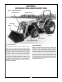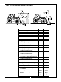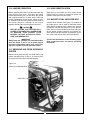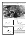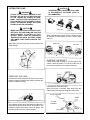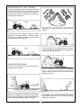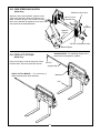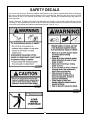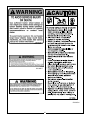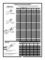
1
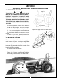
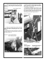
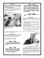
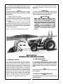
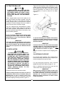
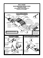
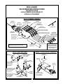
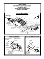
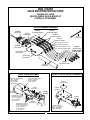
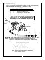
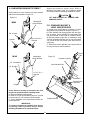
BUSH HOG
®
Front End Loaders
M146 / M246
OPERATOR’S MANUAL
ASSEMBLY ● OPERATION ● MAINTENANCE
401
$4.00
50029373
CONGRATULATIONS!
You have invested in the best implement of its type on the market today.
The care you give your Bush Hog implement will greatly determine your satisfaction
with its performance and its service life. We urge a careful study of this manual to provide
you with a thorough understanding of your new implement before operating, as well as
suggestions for operation and maintenance.
If your manual should become lost or destroyed, Bush Hog will be glad to provide you with
a new copy. Order from Bush Hog, P. O. Box 1039, Selma, Alabama 36702-1039.
As an authorized Bush Hog dealer, we stock genuine Bush Hog parts which are
manufactured with the same precision and skill as our original equipment. Our trained
service personnel are well informed on methods required to service Bush Hog equipment,
and are ready and able to help you.
Should you require additional information or assistance, please contact us.
YOUR AUTHORIZED
BUSH HOG DEALER
BECAUSE BUSH HOG MAINTAINS AN ONGOING
PROGRAM OF PRODUCT IMPROVEMENT, WE
RESERVE THE RIGHT TO MAKE IMPROVEMENTS IN
DESIGN OR CHANGES IN SPECIFICATIONS WITHOUT INCURRING ANY OBLIGATION TO INSTALL
THEM ON UNITS PREVIOUSLY SOLD.
BECAUSE OF THE POSSIBILITY THAT SOME
PHOTOGRAPHS IN THIS MANUAL WERE TAKEN OF
PROTOTYPE MODELS, PRODUCTION MODELS MAY
VARY IN SOME DETAIL. IN ADDITION, SOME
PHOTOGRAPHS MAY SHOW SHIELDS REMOVED
FOR PURPOSES OF CLARITY. NEVER OPERATE
THIS IMPLEMENT WITHOUT ALL SHIELDS IN PLACE.
M146 / M246 Front End Loader
TABLE OF CONTENTS
SECTION/PARA
SECTION/PARA
PAGE
Warranty ............................................................2
Dealer Preparation Check List ...........................3
Safety Alert Symbols..........................................4
Safety Precautions.............................................5
Federal Laws & Regulations ..............................7
I
INTRODUCTION & DESCRIPTION ..................8
1-1 Introduction ..................................................8
1-2 Description...................................................8
II
LOADER MOUNTING & DISMOUNTING........10
PAGE
3-13 Bucket Level Indicator Rod......................15
3-14 Transporting.............................................20
3-15 Fork Lift Operation ...................................20
3-16 Quick Hitch Operation..............................21
IV MAINTENANCE...............................................22
4-1 Maintenance Check List............................22
4-2 Lubrication.................................................22
4-3 Hydraulic System
Pressure Requirements.............................23
4-4 Troubleshooting ........................................23
2-1 Preparing Tractors .....................................10
2-2 Mounting Loader........................................10
2-3 Dismounting Loader ..................................12
V ASSEMBLY......................................................25
5-1 Tractor Preparation....................................25
5-2 Tractor Ballast............................................26
5-3 Installation..................................................26
5-4 Hydraulic Hookup ......................................26
5-5 Valve Mounting M146 Small Valve ............27
5-6 Valve Mounting M146 Series Valve...........28
5-7 Valve Mounting M246 Small Valve ............29
5-8 Valve Mounting M246 Series Valve...........30
5-9 Power Beyond Kit ......................................31
5-10 Mounting Bracket Eyebolt........................32
5-11 Standard Bucket & Level Indicator Rod...32
5-12 Skid Steer Quick Hitch.............................33
5-13 Fork Lift Option ........................................33
Safety Decals...................................................34
Torque Specifications ......................................36
III OPERATING INSTRUCTIONS........................13
3-1 General Safety...........................................13
3-2 Pre Operation ............................................13
3-3 Initial Loader Operation .............................13
3-4 External Loader and/or Tractor Valve........14
3-5 Loader Mounted or Tractor Mounted
Single Lever Control Handle ............................14
3-6 Loader Mounted or Tractor Mounted Two
Control Handles ...............................................14
3-7 Neutral Position .........................................14
3-8 Float Position .............................................14
3-9 Loader Sense Loader Valve ......................14
3-10 Loader Operation.....................................15
3-11 Removing Air From Hydraulic System.......15
3-12 Hose Identification ...................................15
RETAIL CUSTOMER’S RESPONSIBILITY
UNDER THE BUSH HOG WARRANTY
It is the Retail Customer and/or Operator’s responsibility to read the Operator’s Manual, to operate, lubricate,
maintain and store the product in accordance with all instructions and safety procedures. Failure of the operator to read the Operator’s Manual is a misuse of this equipment.
It is the Retail Customer and/or Operator’s responsibility to inspect the product and to have any part(s) repaired
or replaced when continued operation would cause damage or excessive wear to other parts or cause a safety
hazard.
It is the Retail Customer’s responsibility to deliver the product to the authorized Bush Hog Dealer, from whom
he purchased it, for service or replacement of defective parts which are covered by warranty. Repairs to be
submitted for warranty consideration must be made within forty-five (45) days of failure.
It is the Retail Customer’s responsibility for any cost incurred by the Dealer for traveling to or hauling of the
product for the purpose of performing a warranty obligation or inspection.
1
BUSH HOG®
LIMITED WARRANTY
✯✯✯✯✯✯✯✯✯✯✯✯✯✯✯✯✯✯✯✯✯✯✯✯✯✯✯✯✯✯✯
Bush Hog warrants to the original purchaser of any new Bush Hog equipment, purchased from an
authorized Bush Hog dealer, that the equipment be free from defects in material and workmanship for a period
of one (1) year for non-commercial, state, and municipalities’ use and ninety (90) days for commercial use from
date of retail sale. The obligation of Bush Hog to the purchaser under this warranty is limited to the repair or
replacement of defective parts.
Replacement or repair parts installed in the equipment covered by this limited warranty are warranted
for ninety (90) days from the date of purchase of such part or to the expiration of the applicable new equipment warranty period, whichever occurs later. Warranted parts shall be provided at no cost to the user at an
authorized Bush Hog dealer during regular working hours. Bush Hog reserves the right to inspect any equipment or parts which are claimed to have been defective in material or workmanship.
DISCLAIMER OF IMPLIED WARRANTIES & CONSEQUENTIAL DAMAGES
Bush Hog’s obligation under this limited warranty, to the extent allowed by law, is in lieu of all warranties, implied or expressed, INCLUDING IMPLIED WARRANTIES OF MERCHANTABILITY AND FITNESS
FOR A PARTICULAR PURPOSE and any liability for incidental and consequential damages with respect to
the sale or use of the items warranted. Such incidental and consequential damages shall include but not be
limited to: transportation charges other than normal freight charges; cost of installation other than cost
approved by Bush Hog; duty; taxes; charges for normal service or adjustment; loss of crops or any other loss of
income; rental of substitute equipment, expenses due to loss, damage, detention or delay in the delivery of
equipment or parts resulting from acts beyond the control of Bush Hog.
THIS LIMITED WARRANTY SHALL NOT APPLY:
1. To vendor items which carry their own warranties, such as engines, tires, and tubes.
2. If the unit has been subjected to misapplication, abuse, misuse, negligence, fire or other accident.
3. If parts not made or supplied by Bush Hog have been used in connection with the unit, if, in the sole judgement of Bush Hog such use affects its performance, stability or reliability.
4. If the unit has been altered or repaired outside of an authorized Bush Hog dealership in a manner
which, in the sole judgement of Bush Hog, affects its performance, stability or reliability.
5. To normal maintenance service and normal replacement items such as gearbox lubricant, hydraulic fluid,
worn blades, or to normal deterioration of such things as belts and exterior finish due to use or
exposure.
6. To expendable or wear items such as teeth, chains, sprockets, belts, springs and any other items that in the
company’s sole judgement is a wear item.
NO EMPLOYEE OR REPRESENTATIVE OF BUSH HOG IS AUTHORIZED TO CHANGE THIS LIMITED WARRANTY IN ANY WAY OR GRANT ANY OTHER WARRANTY UNLESS SUCH CHANGE IS MADE
IN WRITING AND SIGNED BY BUSH HOG’S SERVICE MANAGER, POST OFFICE BOX 1039, SELMA,
ALABAMA 36702-1039.
✯✯✯✯✯✯✯✯✯✯✯✯✯✯✯✯✯✯✯✯✯✯✯✯✯✯✯✯✯✯✯
Record the model number, serial number and date
purchased. This information will be helpful to your
dealer if parts or service are required.
MODEL NUMBER
SERIAL NUMBER
MAKE CERTAIN THE WARRANTY REGISTRATION
CARD HAS BEEN FILED WITH BUSH HOG/
SELMA, ALABAMA
DATE OF RETAIL SALE
2
DEALER PREPARATION CHECK LIST
M146 & M246 LOADERS
BEFORE DELIVERING MACHINE - The following check list should be completed.
Use the Operator’s Manual as a guide.
❏ Machine properly assembled.
❏ All safety decals readable. (See decal page)
❏ All bolts tightened to torque specifications given in torque chart.
❏ Machine operates properly.
❏ Customer has appropriate mounting kit for his tractor and loader.
❏ Customer has appropriate attachments for loader operations. ( Buckets for lifting loose
materials; bale spear for lifting round bales; fork lift for lifting palletized material)
CAUTION
IT IS RECOMMENDED THAT TRACTOR BE
EQUIPPED WITH ROLLOVER PROTECTIVE SYSTEM (ROPS) AND SEAT BELT BE USED FOR ALL
LOADER OPERATIONS.
❏ Operators manual has been delivered to owner and he has been instructed on the safe
and proper use of the front end loader.
Dealer’s Signature
THIS CHECK LIST TO REMAIN IN OPERATOR’S MANUAL
It is the responsibility of the dealer to complete the procedures listed
above before delivery of this implement to the customer.
3
Safety Alert Symbol
This Safety Alert Symbol means: “ATTENTION! BECOME ALERT!
YOUR SAFETY IS INVOLVED!”
This symbol is used to call attention to safety
precautions that should be followed by the
operator to avoid accidents. When you see this
symbol, carefully read the message that follows
and heed its advice. Failure to comply with safety precautions could result in death or serious
bodily injury.
Safety Signs
Signal Words
The signal words DANGER, WARNING, AND CAUTION are used on the equipment safety signs. These words
are intended to alert the viewer to the existence and the degree of hazard seriousness.
This signal word indicates a potentially hazardous situation
which, if not avoided, will result in death or serious injury.
White letters on RED
This signal word indicates a potentially hazardous situation
which, if not avoided, could result in death or serious injury
It may also be used to alert against unsafe practices.
Black letters on ORANGE
This signal word indicates a potentially hazardous situation exist
which, if not avoided, may result in minor or moderate injury.
It may also be used to alert against unsafe practices.
Black letters on YELLOW
4
IMPORTANT SAFETY PRECAUTIONS
This symbol is used to call attention to safety precautions that should be followed by
the operator to avoid accidents. When you
see this symbol, carefully read the message
that follows and heed its advice. Failure to
comply with safety precautions could result
in death or serious bodily injury.
In addition to the design and configuration of equipment, hazard control and accident prevention are dependent upon the
awareness, concern, prudence and proper training of personnel in the operation, transport, maintenance and storage of
equipment. Lack of attention to safety can result in accident, personal injury, reduction of efficiency and worst of all—loss
of life. Watch for safety hazards and correct deficiencies promptly. Use the following safety precautions as a general
guide to safe operations when using this machine. Additional safety precautions are used throughout this manual for
specific operating and maintenance procedures. Read this manual and review the safety precautions often until you know
the limitations.
THE TRACTOR
1. Read the tractor operator’s manual to learn how to operate your tractor safely. Failure to do so could result in serious injury or death and equipment damage.
2. It is recommended that tractor be equipped with Rollover Protective System (ROPS) and a seat belt be used for all
loader operations.
3. Add wheel ballast or rear weight for stability.
4. Move wheels to the tractor manufacturer’s widest recommended settings to increase stability.
5. For better stability, use tractor with wide front axle rather than tricycle front wheels.
6. Move and turn the tractor at low speeds.
7. Stop tractor engine, place transmission in park (or neutral), engage parking brake, lower loader arms to ground,
cycle all hydraulic controls to relieve pressure, allow machine moving parts to stop, remove ignition key to prevent
unauthorized person from starting engine before dismounting tractor or servicing, repairing, or making adjustments
to the equipment.
8. Wear personal protective equipment (PPE), such as, but not limited to, protection for eyes, ears, lungs, head, hands
and feet when operating, servicing, or repairing equipment. Avoid wearing loose clothing or jewelry that may catch
and entangle on equipment moving parts.
THE LOADER
1. Read the loader operator’s manual to learn how to operate your loader safely. Failure to do so could result in serious injury or death and equipment damage.
2. Become familiar with all the machine’s controls and all the caution, warning and danger decals affixed to the
machine before attempting to start or operate.
3. Improper use of a loader can cause serious injury or death.
4. Do not lift or carry anybody on the loader or in the bucket or attachment.
5. Never allow anyone to get under the loader bucket or reach through the booms when the bucket is raised.
6. Do not walk or work under a raised loader bucket or attachment unless it is is securely blocked or held in position
7. Avoid overhead wires and obstacles when loader is raised. Contacting electrical lines can cause electrocution.
8. Make sure all parked loaders on stands are on a hard, level surface.
9. Use a piece of cardboard or wood rather than hands and wear eye protection when searching for hydraulic leaks.
Escaping hydraulic oil under pressure can penetrate skin. If oil is injected into skin, it must be surgically removed
within a few hours by a doctor or gangrene may result.
5
SAFETY PRECAUTIONS CONTINUED
10. Before disconnecting hydraulic lines, relieve all hydraulic pressure.
11. Do not tamper with the relief valve setting. The relief valve is pre-set at the factory. Changing the setting can
cause overloading the loader and tractor and serious operator injury may result.
12. Always wear safety goggles when repairing or servicing machine.
13. When servicing or replacing pins in cylinder ends, buckets, etc., always use a brass drift and hammer. Failure to
do so could result in injury from flying fragments.
14. Replace damaged or illegible safety decals. See decal page for required decals.
15. Do not modify or alter or permit anyone else to modify or alter the loader, any of its components or any loader
function without first consulting your local dealer.
OPERATING THE LOADER
1.
It is the loader owner’s responsibility to instruct and have a person read operator’s manual, safety decals and
become familiar with machine controls before allowing them to operate loader.
2.
Do not allow children to operate the loader.
3.
Before starting or operating the equipment, make a walk around inspection and check for loose or damaged
components. Correct any deficiency before starting.
4.
Keep the area of operation clear of all persons, particularly small children. The operator should cease operation
whenever anyone comes within the operating area.
5.
Operate the loader from the “Operator’s Seat Only.”
6.
Exercise caution when operating the loader with a raised loaded bucket, fork, or large round hay bale handling
attachments.
7.
Avoid loose fill, rocks and holes. They can be dangerous for loader operation or movement.
8.
Be extra careful when working on inclines.
9.
Allow for the loader length when making turns.
10. Stop the loader arms gradually when lowering or lifting.
11. Use caution when handling loose or shiftable loads.
12. Carry loader arms at a low position during transport.
13. Lower loader arms, stop engine, and lock brakes before leaving the tractor seat.
14. Operate the loader controls only when properly seated at the controls.
15. Do not use loader for handling large, heavy objects such as logs, oil drums, etc.
16. Handling large, heavy objects is dangerous due to:
*Possibility of rolling the tractor over.
*Possibility of upending the tractor.
*Possibility of the object rolling or sliding down the loader arms onto the operator.
17. Use large round hay bale handler attachment with bale retaining devices (grapples, bale spears, clamps, etc.) to
handle large round hay bales. Failure to use retaining devices could allow round hay bales to roll or fall down
loader boom arms onto the operator causing serious injury or death and equipment damage.
6
IMPORTANT FEDERAL LAWS AND REGULATIONS* CONCERNING
EMPLOYERS, EMPLOYEES AND OPERATIONS.
*(This section is intended to explain in broad terms the concept and effect of the following federal laws and
regulations. It is not intended as a legal interpretation of the laws and should not be considered as such).
U.S. Public Law 91-596 (The Williams-Steiger Occupational and Health Act of 1970) OSHA
This Act Seeks:
“...to assure so far as possible every working man and woman in the nation safe and healthful working
conditions and to preserve our human resources...”
DUTIES
Sec. 5 (a) Each employer—
(1) shall furnish to each of his employees employment and a place of employment
which are free from recognized hazards that are causing or are likely to cause
death or serious physical harm to his employees;
(2) shall comply with occupational safety and health standards promulgated under
this Act.
(b) Each employee shall comply with occupational safety and health standards
and all rules, regulations and orders issued pursuant to this Act which are
applicable to his own actions and conduct.
OSHA Regulations
Current OSHA regulations state in part: “At the time of initial assignment and at least annually thereafter, the
employer shall instruct every employee in the safe operation and servicing of all equipment with which the
employee is, or will be involved.” These will include (but are not limited to) instructions to:
Keep all guards in place when the machine is in operation;
Permit no riders on equipment;
Stop engine, disconnect the power source, and wait for all machine movement to stop before
servicing, adjusting, cleaning or unclogging the equipment, except where the machine must be
running to be properly serviced or maintained, in which case the employer shall instruct employees
as to all steps and procedures which are necessary to safely service or maintain the equipment.
Make sure everyone is clear of machinery before starting the engine, engaging power, or operating
the machine.
EMPLOYEE TRACTOR OPERATING INSTRUCTIONS:
1. Securely fasten your seat belt if the tractor has a
ROPS.
5. Watch where you are going, especially at row
ends, on roads, and around trees.
2. Where possible, avoid operating the tractor near
ditches, embankments, and holes.
6. Do not permit others to ride.
7. Operate the tractor smoothly - no jerky turns,
starts, or stops.
3. Reduce speed when turning, crossing slopes, and
on rough, slick, or muddy surfaces.
8. Hitch only to the drawbar and hitch points recommended by tractor manufacturers.
4. Stay off slopes too steep for safe operation.
9. When tractor is stopped, set brakes securely and
use park lock if available.
Child Labor Under 16 Years Old
Some regulations specify that no one under the age of 16 may operate power machinery. It is your
responsibility to know what these regulations are in your own area or situation. (Refer to U.S. Dept. of
Labor, Employment Standard Administration, Wage & Home Division, Child Labor Bulletin #102.)
7
SECTION I
INTRODUCTION AND DESCRIPTION
Figure 1-1 Major Components
Bucket Cylinder
Mainframe Boom
Cross Tube
Bucket
Subframe
Boom Cylinder
Parking Stands Stored
1-1 INTRODUCTION
1-2 DESCRIPTION
We are pleased to have you as a Bush Hog customer. Your Front End Loader has been carefully
designed to give maximum service with minimum
down time. This manual is provided to give you the
necessary operating and maintenance instructions
for keeping your front end loader in top operating
condition. Please read this manual thoroughly.
Understand what each control is for and how to use
it. Observe all safety precautions decaled on the
machine and noted throughout the manual for safe
operation of this implement. If any assistance or
additional information is needed, contact your authorized Bush Hog dealer.
Model M146 & M246 Front End Loaders are
designed for two wheel and four wheel drive tractors. They come equipped with parking stands to
support the loader so the tractor can be “driven in”
for quick attachment and a bucket level indicator that
allows the operator to gauge bucket position when
the bucket cannot be seen. Available attachments
include buckets for lifting loose materials and a fork
lift (M246 Models only) for palletized material. All
operations should be conducted within the loader
limits specified in Table 1-1.
8
Table 1-1 TECHNICAL SPECIFICATIONS
VV
U
V
D
E
XX
A
B
J
C
X
W
ZZ
G
F
Y
H
SERIES LOADER
M246
M146
A.
103 in.
86 in.
Maximum Lift Height - Measured at Pivot Pin
B.
Maximum Lift Height - Under Level Bucket
96 in.
81 in.
C.
Clearance with Attachment Dumped 45°
77 in.
67 in.
D.
Reach at Maximum Height
22 in.
23 in.
E.
Maximum Dump Angle
40°
45°
62 in.
54 in.
25°
25°
F.
Reach with Bucket on Ground
G.
Maximum Rollback Angle
H.
Digging Depth
5 in.
5 in.
J.
Overall Height in Carry Position
56 in.
48 in.
U.
Lift Capacity to Maximum Height - At Pivot Pin
1530 lbs.
825 lbs.
V.
Lift Capacity to Maximum Height - 31.5” (M246),
19.7” (M146) Forward of Pivot Pin
880 lbs.
570 lbs.
W.
Lift Capacity to 59” Height - At Pivot Pin
1730 lbs.
940 lbs.
X.
Lift Capacity to 59” Height - 31.5” (M246),
19.7 (M146) Forward of Pivot Pin
1195 lbs.
710 lbs.
Y.
Breakout Force - At Pivot Pin
2370 lbs.
1335 lbs.
Z.
Breakout Force - 31.5” (M246),
19.7 (M146) Forward of Pivot Pin
1530 lbs.
965 lbs.
V V. Rollback Force at Maximum Height 31.5” (M246), 19.7 (M146) Forward of Pivot Pin
1625 lbs.
1935 lbs.
XX. Rollback Force at 59” Height - 31.5” (M246),
19.7 (M146) Forward of Pivot Pin
2020 lbs.
2300 lbs.
ZZ. Rollback Force at Ground Level - 31.5” (M246),
19.7 (M146) Forward of Pivot Pin
1680 lbs.
1700 lbs.
Raising Time - Ground Level to Full Height
4 sec.
3.5 sec.
Lowering Time - Full Height to Ground
2 sec.
2.5 sec.
Bucket Dumping Time - Full Rollback
to Full Dump
3 sec.
4.0 sec.
Bucket Rollback Time - Full Dump
to Full Rollback
2 sec.
3.0 sec.
20 - 30
2 & 4 WD
15 -25
2 & 4 WD
2000 psi
10 gpm
1875 psi
6.0 gpm
Tractor HP Range
Based On Tractor Hydraulic System:
Pressure
Flow
9
Z
SECTION II
LOADER MOUNTING AND DISMOUNTING
2-1 PREPARING TRACTOR
Figure 2-1
CAUTION
TRACTORS THAT HAVE MOVABLE AXLES
MUST BE SET FORWARD IN THE LONG WHEELBASE POSITION AS SHOWN IN FIGURE 2-1 TO
PREVENT EXCESSIVE LEVERAGE BEING
EXERTED ON THE TRACTOR FRAME. FAILURE
TO DO SO CAN RESULT IN PERSONAL INJURY
AND EQUIPMENT DAMAGE. REFER TO TRACTOR OPERATOR’S MANUAL FOR ABOVE PROCEDURES AND SPECIFICATIONS FOR YOUR
TRACTOR.
Short Wheelbase
Long Wheelbase
A. Check air pressure in tractor tires to be sure it
is adequate for heavy loads.
B. Add rear wheel weights, fluid in tires, or equivalent to provide sufficient tractor stability.
C. It is recommended that tractor wheels be
moved to the widest settings.
D. Check tractor hydraulic oil reservoir to be sure
it is full.
E. Refer to your tractor operator’s manual for
above procedures and specifications for your tractor.
Figure 2-2
2-2 MOUNTING LOADER
To aid in mounting and dismounting loader, apply a
small amount of grease, if needed, to each loader
bracket in area of top receiver and guide. Figure 2-2.
A. Slowly drive tractor to a position where the
hoses can be connected to the quick couplers. Stop
the engine. (Figure 2-3) Connect the loader hydraulic
hoses to the correct couplers.
B. Retract Loader Lift Cylinders.
Figure 2-3 Drive In Close Enough To Alllow
Connecting Hydraulic Hoses To Tractor Outlets
10
Apply Grease To These Areas
C. Check that lift cylinders are fully retracted.
Figure 2-3. Then drive tractor forward. Use bucket
cylinders to position height of outer pedestal top pin.
Figure 2-4.
Figure 2-4
F. Extend lift cylinders slowly making sure loader is
seated completely in mounting bracket top and bottom receivers. Retract bucket cylinder until bucket is
approximately 1/2” off ground.
G. Remove lockwasher, quick attach nut, and
self storing tool from holder. Remove quick pin and
clamp from storage position. Place clamp and quick
pin in working position. Install quick attach nut and
lockwasher to eyebolt using self storing tool. Store
self storing tool in holder. Figures 2-6 & 2-7.
Outer Pedestal Top Pin
Figure 2-6 Eyebolt
Clamp And Pins In Stored Position
D. Align outer pedestal top pin with mounting
bracket guide post on both sides.(Figures 2-2, & 2-4)
Make sure loader is centered right to left on both
brackets.
E. Extend the bucket cylinders to lower the
pedestal top pins into mounting bracket receivers on
both sides. Figure 2-5
Figure 2-5 Loader Installed With All
Pins In Working Position
Quick Attach Nut
Figure 2-7
Clamp Installed In
Working Position
11
Lockwasher
Tightening Quick Attach Nut
Using Self Storing Tool
IMPORTANT
Each time after mounting the loader, operate
loader for a short period of time, then retighten
the quick attach nuts. Check nuts for tightness
during normal maintenance
H. Remove parking stands from the parked position and return them to their storage positions in the
cross tube. Secure parking stands in the storage
position by using pins. Figure 2-8.
CAUTION
DO NOT STAND, WALK, OR WORK UNDER
A RAISED LOADER OR ATTACHMENT
UNLESS IT IS SECURELY BLOCKED OR
HELD IN POSITION. ACCIDENTAL MOVEMENT OF A CONTROL LEVER/LEVERS OR
LEAKS IN THE HYDRAULIC SYSTEM
COULD CAUSE THE LOADER TO DROP,
OR ATTACHMENT TO DUMP, CAUSING
SEVERE INJURY.
Figure 2-8 Parking Stands
Preparing To Store Stands
Stands In Stored Position
CAUTION
DO NOT ALLOW BYSTANDERS IN LOADER
AREA.
IMPORTANT
Never allow weight of tractor to be placed on
parking stands when mounting or dismounting
loader.
A. Position the loader on a hard level surface.
The more level the surface, the easier the loader is
to mount and dismount.
B. Raise loader, dump bucket over, and then
lower loader so that bucket cutting edge is approximately 1/2” off of ground.
C. Remove parking stands from their storage
positions in the boom crosstube as shown in Figure
2-8.
D. Position parking stands in attaching brackets
on inside of each loader arm and secure. Figure 2-9.
Pin Through Cross Tube
Will Secure Stands In
Place
Figure 2-9 Parking Stands Installed
I. Lower loader to ground and secure loader
hydraulic hoses in a protected area.
Attaching Bracket
IMPORTANT
To avoid hydraulic hose damage, be alert and
make sure hoses do not catch on tractor and/or
loader during mounting or dismounting.
2-3 DISMOUNTING LOADER
CAUTION
ALWAYS PARK LOADER WITH MATERIAL BUCKET OR AUTHORIZED BUSH
HOG ATTACHMENT ATTACHED TO THE
LOADER.
Parking Stands With Flat Side Down
E. Dismounting procedures will be the reverse of
the mounting procedure. Refer to Figures 2-3 -- 2-7.
Remove self storing tool from holder. Remove quick
attach nut and lockwasher from eyebolt using self
storing tool. Remove quick pin and clamp from working position. Place clamp and quick pin in storage
position. Store lockwasher, quick attach nut, and self
storing tool in holder.
CAUTION
BEFORE LEAVING THE TRACTOR SEAT,
LOWER ATTACHMENT OR LOADER
BOOM TO GROUND, STOP ENGINE,
LOCK BRAKES, RELIEVE HYDRAULIC
PRESSURE, AND REMOVE KEY.
12
F. Rollback bucket slightly while lowering loader
boom down until the parking stands make firm contact with ground. Dump bucket until bucket touches
the ground.
NOTE
Driving the tractor forward slowly while positioning loader will allow parking stands to contact
ground firmly.
J. Disconnect loader hoses from quick couplers.
Start tractor and slowly back tractor away from loader.
Figure 2-10.
IMPORTANT
To avoid hydraulic hose damage, be alert and
make sure hoses do not catch on tractor and/or
loader during mounting or dismounting.
G. Retract loader lift cylinders
H. Slowly rollback bucket while driving slightly
forward with tractor. Doing this will allow mounting
brackets to guide loader as loader is being parked
off of tractor.
I. Rollback bucket completely. Make sure all loader
components clear tractor. Stop the tractor engine and
then work valve control lever/levers to relieve hydraulic
fluid pressure in lines. Refer to tractor operator manual
for additional information.
WARNING
MAKE SURE PARKED LOADER IS ON A
HARD LEVEL SURFACE. ENGAGE ALL
SAFETY DEVICES TO PREVENT LOADER
FROM FALLING AND BEING DAMAGED
OR INJURING SOMEONE. DO NOT REPAIR
LOADER IF IT IS NOT MOUNTED ON THE
TRACTOR. LOSS OF HYDRAULIC FLUID
OR REMOVAL OF PARTS COULD CAUSE
LOADER TO COLLAPSE RESULTING IN
INJURY.
Figure 2-10 Backing Tractor Away From Loader
SECTION III
OPERATING INSTRUCTIONS
3-2 PRE-OPERATION
3-1 GENERAL SAFETY
IMPORTANT
Do not extend bucket cylinders without bucket
or quick hitch attachment installed on loader.
Failure to follow these instructions could cause
bucket cylinder damage and will void loader warranty.
Only qualified people familiar with this operator’s
manual should operate this machine. Operator
should wear hard hat, safety glasses, and safety
shoes. The operator should read, understand and
practice all safety messages shown on the caution,
warning and danger decals affixed to the loader to
avoid serious injury or death. It is recommended that
tractor be equipped with Rollover Protective System
(ROPS) and a seat belt be used. Check for ditches,
stumps, holes or other obstacles that could upset
tractor or damage loader. Always turn off tractor
engine, set parking brake, and lower loader to
ground before leaving tractor operator’s seat.
NOTE
Check the tractor hydraulic fluid reservoir and
fill, if required.
3-3 INITIAL LOADER OPERATION
NOTE
Keep engine speed at low idle during the initial
loader operation.
13
3-6 LOADER MOUNTED SERIES CONTROL VALVE EQUIPPED WITH SINGLE
LEVER CONTROL HANDLE
WARNING
ESCAPING HYDRAULIC FLUID UNDER
PRESSURE CAN HAVE SUFFICIENT FORCE
TO PENETRATE SKIN, CAUSING SERIOUS
PERSONAL INJURY. BEFORE APPLYING
PRESSURE TO SYSTEM, BE SURE ALL
CONNECTIONS ARE TIGHT AND THAT
LINES, TUBES, AND HOSES ARE NOT DAMAGED. FLUID ESCAPING FROM A VERY
SMALL HOLE CAN BE ALMOST INVISIBLE.
USE A PIECE OF CARDBOARD OR WOOD,
RATHER THAN HANDS, TO SEARCH FOR
SUSPECTED LEAKS. IF INJURED BY
ESCAPING FLUID, SEE A DOCTOR AT
ONCE. SERIOUS INFECTION OR REACTION
CAN DEVELOP IF PROPER MEDICAL
TREATMENT IS NOT ADMINISTERED IMMEDIATELY.
If your loader utilizes a loader mounted series control valve equipped with single lever control handle,
it will function as shown in Figure 3-2.
Figure 3-2
3-7 NEUTRAL POSITION
3-4 EXTERNAL LOADER AND/OR TRACTOR VALVE.
The loader external valve provided by Bush Hog has
a “neutral position” which prevents movement of the
loader or attachment. When the control handle is
manually released from the work position, the valve
spool will return to the neutral position.
NOTE
When properly installed, the tractor remote valve
or external valve control lever/levers will control
the loader hydraulic circuits as described below.
Refer to tractor Operator’s Manual for further
explanation of tractor remote control
lever/levers.
3-8 FLOAT POSITION
The loader external valve provided by Bush Hog has
a “float position” incorporated into the lift cylinder circuit which allows the loader to float. This float feature is important for satisfactory operation when
scraping, sweeping, leveling, or any job where it is
necessary to follow the contour of the surface. To
activate the float position, lower the bucket or attachment and push the control handle all the way forward into detent. The valve will stay in float detent
position until the operator manually pulls the control
handle out of detent position to deactivate float.
IMPORTANT
Contaminants in hydraulic fluid can cause valve
spools to stick. BE ALERT when operating
loader and follow your tractor Operator’s Manual
hydraulic fluid maintenance schedule.
3-5 LOADER MOUNTED CONTROL
VALVE EQUIPPED WITH SINGLE LEVER
CONTROL HANDLE OR TRACTOR
REMOTE VALVE EQUIPPED WITH SINGLE LEVER CONTROL HANDLE
If your loader utilizes a loader control valve equipped
with single lever control handle or tractor remote
valve equipped with single lever control handle, it will
function as shown in Figure 3-1.
3-9 LOAD SENSE LOADER VALVE.
IMPORTANT
If your loader is equipped with a load sense type
control valve it may demonstrate the following
operation characteristic. Attempting to raise the
boom by finely feathering the control lever may
actually allow the boom to lower very slowly. To
prevent this from happening, move the control
lever far enough to ensure that the boom raises.
Figure 3-1
14
3-10 LOADER OPERATION
3-12 HOSE IDENTIFICATION
Before operating the loader, fully raise and lower the
boom three or four times. Then raise the loader
bucket approximately four (4) feet above the ground
and cycle the bucket two or three times. Lower the
bucket or attachment to the ground. Check the tractor hydraulic fluid level and fill as required. Refer to
the tractor Operator’s Manual for the proper
hydraulic fluid and the correct hydraulic fluid level.
Metal lines on the loader are color coded. Check
loader functions. Refer to instruction sheets for
hydraulic valve option on your loader.
3-13 BUCKET LEVEL INDICATOR ROD
A bucket level indicator rod (Figure 3-3), located on
the loader frame, can be used to determine bucket
angle. Before beginning work, observe the position
of indicator rod with the bucket flat on the ground.
Raise boom to several different positions and operate the bucket cylinders. Observe the indicator rod.
Once familiar with the indicator rod positions, operation of the loader will be easier and more efficient.
CAUTION
BEFORE LEAVING THE TRACTOR SEAT,
LOWER ATTACHMENT OR LOADER BOOM
TO GROUND, STOP ENGINE, LOCK
BRAKES, RELIEVE HYDRAULIC PRESSURE, AND REMOVE KEY.
IMPORTANT
Always keep the cylinders in a retracted position
when the loader is not in use to guard against
rust and contamination which may cause damage to the cylinder rods and hydraulic system.
The text and illustrations on the following pages
offer suggested loader and tractor operating
techniques.
3-11 REMOVING AIR FROM HYDRAULIC
SYSTEM
Repeat raising and lowering the loader boom and
bucket operations until all the air is removed from
the system and the system responds properly.
Figure 3-3
Bucket Level Indicator Rod
Guide Tube
15
The text and illustrations that follow offer suggested loader and tractor
operating techniques.
FILLING THE BUCKET
Approach and enter the pile with a level bucket.
The lift and rollback of the bucket will increase
efficiency because...
DO THIS
... a level bucket throughout the lifting cycle resists
bucket lift and increases breakaway effort.
Ease lever back and toward you to lift and rollback
the bucket.
NOT THIS
1-LEVER CONTROL
ROLLBACK
NOTE: Do not be concerned if the bucket is not completely filled during each pass. Maximum productivity is determined by the amount of material loaded in
a given period of time. Time is lost if two or more
attempts are made to fill the bucket on each pass.
LIFT
16
LIFTING THE LOAD
CAUTION
OPERATING THE LOADER ON A HILLSIDE
IS DANGEROUS. EXTREME CARE IS
RECOMMENDED.
WARNING
DO NOT LIFT OR CARRY ANYONE IN THE
BUCKET OR ON ANY OTHER POSITION
OF THE LOADER OR LOADER ATTACHMENT. INADVERTENT MOVEMENT OF
THE LOADER OR ATTACHMENT COULD
RESULT IN SERIOUS INJURY OR DEATH
FROM FALLING OR CRUSHING.
CAUTION
DO THIS
NOT THIS
MAKE SURE MATERIAL IN BUCKET CANNOT ROLL OUT AND DOWN ON TRACTOR
WHEN BUCKET IS RAISED TO FULL
HEIGHT. KEEP CLEAR OF OVERHEAD
OBSTRUCTIONS SUCH AS TREES, LIMBS
OR POWER LINES WHEN RAISING THE
BUCKET.
When transporting the load, keep the bucket as low
as possible to avoid tipping in case a wheel drops
into a rut.
NOT THIS
When lifting the load, keep the bucket positioned to
avoid spillage.
DO THIS
DUMPING THE BUCKET
Lift the bucket high enough to clear the side of the
vehicle. Move the tractor in as close to the side of
the vehicle as possible, then dump the bucket.
CARRYING THE LOAD
Position the bucket just below the level of the tractor
hood for maximum stability and visibility, whether the
bucket is loaded or empty.
LOWERING THE BUCKET
After the bucket is dumped, back away from the
vehicle while lowering and rolling back the bucket.
FLOAT POSITION
LOWER
DUMP
1-LEVER
CONTROL
Use extreme caution when operating the loader on a
slope and keep the bucket as low as possible. This
keeps the bucket and tractor center of gravity low
and will provide maximum tractor stability.
ROLLBACK
17
RAISE
OPERATING WITH FLOAT CONTROL
During hard surface operation, keep the bucket level
and put the lift control in the float position to permit
the bucket to float on the working surface. If
hydraulic down pressure is exerted on the bucket, it
will wear faster than normal.
FLOAT
Sidecutting is a good technique for cutting down a
big pile.
The float will also prevent the mixing of surface
material with stockpile material. The float position
will reduce the chance of surface gouging when
removing snow or other material.
FLOAT
If the pile sides are too high and liable to cause
cave-in, use the loader to break down the sides until
a slot can be cut over the top.
SURFACE MATERIAL
LOADING FROM A BANK
Choose a forward gear that provides sufficient
ground speed for loading.
Another method for large dirt piles is to build a ramp
approach to the pile.
Exercise caution when undercutting high banks. Dirt
slides can be dangerous. Load from as low as possible for maximum efficiency. Loader lift and breakaway
capacity diminish as loading height is increased.
It is important to keep the bucket level when
approaching a bank or pile. This will help prevent
gouging the work area.
18
PEELING AND SCRAPING
BACKFILLING
DO THIS
6”
Backgrade occasionally with a loaded bucket to
keep the working surface free of ruts and holes.
Hold the lift control forward in FLOAT POSITION so
the full weight of the bucket is scraping the ground.
Use only the heel of the bucket while backgrading.
Use a slight bucket angle, travel forward, and hold the
lift control forward to start the cut. Make a short, angle
cut approximately 6” deep and break-out cleanly.
NOT THIS
With the bucket level, start a cut at the notch approximately 2” deep. Hold the depth by feathering the
bucket control to adjust the cutting lip up or down.
When the front tires enter the notch, adjust the lift
cylinder to maintain proper depth.
IMPORTANT: To prevent damage to cylinders:
(1) Do not backgrade with bucket cylinders extended.
(2) Always backgrade with valve in float position.
3RD CUT , 4TH CUT, ETC.
Approach the pile with a flat bucket.
DO THIS
Make additional passes until the desired depth is
reached. During each pass, only use the bucket control while at working depth. This will allow you to
concentrate on controlling the bucket angle to maintain a precise cut.
LOADING LOW TRUCKS OR SPREADERS FROM
A PILE
NOT THIS
Poor methods actually move no more dirt and make
it more difficult to hold a level grade.
Do not use the bucket in the dumped position
for bulldozing or backgrading. This method,
shown above, will impose severe shock loadings on the dump linkage, the bucket cylinder,
and the tractor.
For faster loading, minimize the angle of turn and
length of run between pile and spreader.
19
HANDLING LARGE HEAVY OBJECTS
WARNING
Do not use front end loaders for handling large,
heavy objects such as large, round or rectangular bales, logs and oil drums.
Handling large heavy objects can be extremely
dangerous due to:
★ Possibility of rolling the tractor over.
★ Possibility of upending the tractor.
Leave dirt in the bucket because dumping on each
pass wastes time.
★ Possibility of the object rolling or sliding
down the loader arms onto the operator.
3-14 TRANSPORTING
DITCH
When transporting on road or highway, day or
night, use tractor flashing warning lights unless prohibited by law. Carry load as low as possible maintaining adequate ground clearance and visibility.
Reduce tractor ground speed when transporting a
load. Take extra care when traveling over rough
terrain or on slopes.
SOIL PILE
CAUTION
WHEN TRANSPORTING THE LOAD, KEEP THE
BUCKET AS LOW AS POSSIBLE TO RESIST TIPPING IN CASE A WHEEL DROPS IN A RUT. THIS
WILL AVOID TIPPING AND POSSIBLE INJURY.
Operate at right angles to the ditch. Take as big a
bite as the tractor can handle without lugging down.
NOTE
DITCH
When loader hydraulics are disconnected
from tractor the tractor hydraulic circuit
must be completed. Failure to do so will
result in tractor hydraulic pump damage.
3-15 FORK LIFT OPERATION (M246 ONLY)
WARNING
TO AVOID SERIOUS INJURY OR DEATH:
★ NEVER LIFT LARGE ROUND HAY
BALES OR OTHER LOADS ON THE
FORK LIFT ATTACHMENT THAT
COULD ROLL BACK ONTO TRACTOR OPERATOR AREA.
★ NEVER USE FORK LIFT ATTACHMENT TO LIFT OR SUPPORT PEOPLE.
★ TRANSPORT LOADS LOW AND SLOW.
★ AVOID CONTACT WITH POWER LINES.
Leave dirt which drifts over the side of the bucket for
final clean-up.
The fork lift attachment (Figure 3-4) is intended for
handling palletized material. It is recommended that
tractor be equipped with ROPS and seat belts. Use
the loader dump cylinders to give the forks the
desired tilt. Position the forks on their support rods
to the desired width so that the load will be carried
approximately equal on each fork. Position load as
far back as possible.
Pile dirt on the high side for easier backfilling on a
slope.
20
3-16 QUICK HITCH OPERATION (M246 ONLY)
Figure 3-4
Fork Lift Attachment
The quick hitch (Figure 3-5) is designed to allow
easy mounting and dismounting of skid steer
attachments from loader. With attachment on flat,
level surface, mount as follows:
Tilt quick hitch slightly forward at top and slowly
drive into attachment.
Adjustable Forks
Hook quick hitch under top cuff on attachment and
lift off ground using boom cylinders only.
Tilt quick hitch backward using bucket cylinder so
that bottom of attachment will swing into position.
Rotate handles downward, locking spring-loaded pins
into place in slot on attachment hitch for operation.
To dismount the attachment:
Tilt quick hitch backward and rotate handles up to
disengage pins. Reverse the mounting procedure.
CAUTION
ALWAYS CHECK TO INSURE THAT QUICK
HITCH SPRING LOADED PIN IS IN THE
LATCHED POSITION BEFORE OPERATING
LOADER OR ACCINDENTAL DISENGAGEMENT OF THE ATTACHMENT COULD
RESULT.
A.
Top Cuff
Quick Hitch Tilted Forward
Figure 3-5 A, B, C, & D
Quick Hitch Operation
Spring-Loaded
Pins Raised
B. Drive Into Attachment
C. Raise And Roll Back Attachment
21
D. Lower Spring-Loaded Pins
SECTION IV
MAINTENANCE
Figure 4-1 Mounting Kit
4-1 MAINTENANCE CHECK LIST
Perform scheduled maintenance as outlined below.
Lower machine to ground, turn off tractor, and set
parking brake before doing maintenance inspections
or work. All bolts should be torqued as recommended in torque chart unless otherwise indicated.
Apply Small Amount
Of Grease
WARNING
THE LOADER CAN FALL FROM
HYDRAULIC SYSTEM FAILURE. TO
AVOID SERIOUS INJURY OR DEATH,
SECURELY SUPPORT LOADER BEFORE
WORKING UNDERNEATH.
Check Torque On All
Mounting Hardware
4-2 LUBRICATION (Figure 4-2)
NOTE
The multi-purpose grease referenced in this section
is an NLGI grade 2 type grease.
BEFORE EACH USE
1. Inspect hydraulic lines and fittings for wear or
leaks. Repair or replace if needed.
BEFORE EACH USE
1. Boom Pivot Pins - Apply multi-purpose grease to
each fitting (1 fitting each side)
2. Boom Cylinders - Apply multi-purpose grease to
each fitting (2 fittings each cylinder)
3. Bucket Cylinders - Apply multi-purpose grease to
each fitting (2 fittings each cylinder)
4. Bucket Pivot Pin - Apply multi-purpose grease
to each fitting (1 fitting each side)
5. Hydraulic Oil - Cycle boom and bucket cylinders
2 or 3 times before each use, then check
hydraulic oil level in tractor reservoir.
2. Inspect all pivot pins for wear. Make certain car
riage bolts, lockwashers and hex nuts are
installed to retain each pivot pin.
3. Check all bolts for tightness.
4. Perform BEFORE EACH USE lubrication per
paragraph 4-2.
5. During operation, listen for abnormal sounds
which might indicate loose parts or other damage.
AFTER EACH USE
1. Clean all debris from machine, especially cylinder
rods and affixed safety decals. Replace any
missing or illegible decals.
2. Inspect loader for worn or damaged components.
Repair or replace before next use. Any replacement components installed during repair shall
include the components’ current safety decals
specified by the manufacturer to be affixed to the
component.
CAUTION
3. Store loader in a dry place.
USE A PIECE OF CARDBOARD OR
WOOD RATHER THAN HANDS AND
WEAR EYE PROTECTION WHEN
SEARCHING FOR HYDRAULIC LEAKS.
ESCAPING HYDRAULIC OIL UNDER
PRESSURE CAN PENETRATE SKIN. IF
OIL IS INJECTED INTO SKIN, IT MUST BE
SURGICALLY REMOVED WITHIN A FEW
HOURS BY A DOCTOR OR GANGRENE
MAY RESULT.
To keep mounting kit hardware from loosening during operation, periodically check that all loader
mounting kit hardware is torqued to specifications
noted in torque chart, Page 36. To aid in mounting
and dismounting loader, apply a small amount of
grease to areas shown in Figure 4-1.
22
Figure 4-2 Lubrication Points
➀
➂
M246
With Optional
Skid Steer
Quick Hitch
➁
➃
➂
➃
M146
Standard Bucket
Attachment
4-4 TROUBLESHOOTING
4-3 HYDRAULIC SYSTEM PRESSURE
REQUIREMENTS
Troubleshooting procedures are listed on page 24.
If the problem cannot be solved or replacement
parts are necessary, contact your authorized Bush
Hog dealer. Please have ready your machine name,
model number, serial number, purchase date and
exact cause or description of problem.
A tractor hydraulic system pressure setting of 2500
psi is recommended for maximum efficiency and service. Do not exceed 3000 psi as this will damage
components possibly causing serious injury.
The Bush Hog control valve is pre-set at the factory
and should not be adjusted.
23
TROUBLESHOOTING PROCEDURES
PROBLEM
POSSIBLE CAUSE
Loader slow and/or will not dump.
Hydraulic oil too heavy.
Oil filter plugged.
Hydraulic pump worn.
Oil line restricted or leaking.
REMEDY
Change to proper oil.
Clean or replace filter.
Repair or replace pump.
Check all hoses and tubes for leaks,
damage or restrictions. Replace
damaged or restricted hoses or tube lines.
Quick couplers not properly connected. Check connection - Replace if necessary.
Control valve does not shift properly.
Inspect clean, repair or replace valve.
Air in hydraulic system.
Cylinder leaks internally.
Cycle lift cylinders and bucket cylinders
several times to free system of air.
Replace seals.
Faulty valve.
Repair or replace valve.
Loader chatters or vibrates when
raising or lowering.
Air in hydraulic system.
Cycle lift cylinders and bucket cylinders.
Oil level too low.
Add oil as required.
Oil leaks.
Damaged fittings or hoses.
Replace damaged parts.
Loose connections.
Tighten fittings.
Worn or damaged O-ring or
wiper seal in cylinder rod end.
Install a seal repair kit.
Worn or damaged O-rings in
valve.
Install an O-ring repair kit.
Load is greater
than boom lift capacity.
Check loader specifications.
Check tractor system.
Internal boom cylinder leakage.
Replace any worn parts and install a seal
repair kit.
Improper hydraulic valve
operation.
Repair or replace valve.
Worn control valve.
Have authorized Bush Hog dealer replace
seals.
Worn cylinder piston seals.
Have authorized Bush Hog dealer replace
seals.
Excessive wear on bottom of bucket
and wear pads.
Float position not used while
operating loader.
Use float position provided on valve.
Hydraulic cylinders inoperative.
Hose from control valve improperly
connected.
Refer to plumbing diagrams in Section V.
Pump operating continually on closed
center tractor hydraulic system.
Hydraulic control valve relief stuck
open.
Hydraulic control valve relief set
too low.
See your tractor manual for proper adjustment or Bush Hog dealer for loader valve.
(3000 PSI is maximum pressure relief
setting recommended)
Valve not correct for closed
center operation
Install closed center plug on optional valve.
Loader lift and bucket tilt controls do not work
according to decal.
Hoses improperly connected.
Refer to plumbing diagrams in Section V
and correct hose connections.
Valve noisy and/or hot.
Open center control valve on
closed center tractor.
Install closed center plug on optional valve.
Tractor loads/pump squeals.
Closed center control valve on open
center tractor.
Install open center plug on optional valve.
Insufficient lift capacity.
Slow leakdown.
24
SECTION V
ASSEMBLY
CAUTION
11. After completing assembly, be sure that all safety locking devices or guards are in place.
THE FOLLOWING SAFETY PRECAUTIONS
SHOULD BE THOROUGHLY UNDERSTOOD BEFORE ATTEMPTING MACHINE
ASSEMBLY.
12. Before operating the machine, thoroughly read
the operation section of this manual.
13. Before operating, read the maintenance section
of this manual to be sure that any parts requiring
lubrication, such as gearboxes, are full to avoid
any possible damage.
1. Do not lift heavy parts or assemblies. Use crane,
jack, tackle, fork trucks, or other mechanical
devices.
2
14. Wear personal protective equipment such as,
but not limited to, protection for eyes, ears, feet,
hands, lungs and head when assembling the
equipment. Do not wear loose clothing or jewelry
that may catch on equipment moving parts.
Select an area for assembly that is clean and
free of any debris which might cause persons
working on the assembly to trip.
3. Arrange parts to be assembled neatly in the work
area and have tools or other mechanical assisting devices in easy reach.
BEFORE OPERATING THE EQUIPMENT, IF YOU
HAVE ANY QUESTIONS REGARDING THE
PROPER ASSEMBLY OR OPERATION, CONTACT YOUR AUTHORIZED BUSH HOG DEALER
OR REPRESENTATIVE.
4. Inspect all parts and assemblies thoroughly and
remove any sharp edges, grease, oil, or dirt
which might cause pieces to slip when handling.
5. Preview the assembly instructions in your operator’s manual before proceeding further.
CAUTION
EQUIP YOUR TRACTOR WITH A ROPS CAB
OR FRAME FOR YOUR PROTECTION. SEE
YOUR TRACTOR/ROPS OPERATOR’S
MANUAL FOR CORRECT SEAT BELT USAGE.
6. If the assembly instructions call for parts or
assemblies to be blocked up, use only blocking
material that is in good condition and is capable
of handling the weight of the assembly to be
blocked. Also insure that the blocking material is
on a clean, dry surface.
7. Never put hands or any other part of body under
blocked up assemblies if at all possible.
Read entire instructions before beginning to install
the loader. Personal injury and machine damage
may be prevented if you read and understand these
instructions and special safety messages.
8. Always wear goggles or safety glasses when
hammering, grinding or drilling metal parts.
Any reference to right or left are as if you were in the
tractor seat facing forward .
9. If the assembly calls for welding or cutting, be
sure that there are no flammable materials close
at hand and that bystanders have taken necessary precautions.
5-1 TRACTOR PREPARATION
Use front tires of equal size and maintain equal pressure in each tire. The pressure of the front tractor
tires must be increased to the maximum approved
pressure recommended by the tire manufacturer to
compensate for additional load placed on the tires
with the front end loader. Refer to your Tractor
Operator’s Manual. Adjust the front tires to the
widest recommended setting on adjustable models
for maximum stability. Front end weights must NOT
be used while loader is on the tractor. Pay particular
attention to “minimum tread settings” infromation in
Installation Instructions included with your Mounting
Kit.
AFTER COMPLETING ANY ASSEMBLY STEP,
THOROUGHLY READ THE NEXT STEP IN THE
ASSEMBLY INSTRUCTIONS BEFORE PROCEEDING WITH THAT STEP.
10. After completing assembly, thoroughly inspect
the machine to be sure that all nuts, bolts,
hydraulic fittings or any other fastened assemblies have been thoroughly tightened.
25
Tighten all bolts equally during installation so that
outside surface of brackets are level and the center
line measurement from right to left hand mounting
brackets (Dimension “A”) reads 32” plus or minus
1/4” for M146 or 37” plus or minus 1/4” for M246.
Figure 5-1.
5-2 TRACTOR BALLAST
CAUTION
TO HELP PREVENT ROLLOVER, USE RECOMMENDED REAR TRACTOR BALLAST
AND WIDEST WHEEL SETTINGS TO MAXIMIZE STABILITY. SEE YOUR TRACTOR
OPERATOR’S MANUAL FOR RECOMMENDATIONS.
Figure 5-1
“A”
Tractor weight bracket may be left in place on certain tractor models with loader mounted. Front tractor weights can only be used when the loader is
parked. Weights must be removed before remounting loader or serious damage will occur to loader or
tractor front axle due to excessive weight.
Bracket
Hole
The use of adequate rear counterweight to counterbalance for maximum loader capacity is required for
safe loader operation. Weight added to the rear of
the tractor provides better traction and easier, more
efficient loader operation.
Mounting
Bracket
IMPORTANT
Do not exceed the maximum load capacity of the
tires on your tractor. Refer to the Tire and Wheel
Specifications in your Tractor Operator’s Manual
for more information.
IMPORTANT
To prevent mounting kit hardware from loosening during operation, always torque mounting kit
hardware to specified torque noted in Loader
Operator’s Manual.
IMPORTANT
This loader has both standard and metric fasteners. Verify that the proper fasteners are placed in
the correct locations. Do not tighten any bolts
firmly until all components are attached onto the
tractor.
IMPORTANT
If external valve is to be used, mount valve stand
assembly, pages 27 - 30, to loader bracket before
installing loader to the loader bracket. Bolts cannot be installed once loader is in place.
5-3 INSTALLATION
Remove all loader components from shipping packaging.
WARNING
TO AVOID SERIOUS INJURY OR DEATH:
READ BEFORE CUTTING BANDS OR
REMOVING ATTACHING STRAPS. THE
LOADER MAY SHIFT DURING SHIPPING
AND HANDLING, MAKING IT UNSTABLE
ON THE PALLET. SUPPORT LOADER
WITH AN OVERHEAD HOIST OR OTHER
SUITABLE MEANS PRIOR TO REMOVING
BANDS OR ATTACHING STRAPS SECURING LOADER TO PALLET. FAILURE TO
DO SO COULD RESULT IN ACCIDENTAL
TIP-OVER OF THE LOADER THAT COULD
CAUSE SERIOUS INJURY TO YOU
AND/OR BYSTANDERS.
5-4 HYDRAULIC HOOKUP
For use with tractor hydraulic valve, install hoses to
loader steel tubing. Install male quick couplers (customer furnished) to free ends of hoses.
For valve and stand mounting, refer to VALVE
MOUNTING INSTRUCTIONS on pages 27 - 30.
Refer to individual instructions that come with the
various other valve and control options.
IMPORTANT
When properly installed, the tractor remote valve
or external valve control lever/levers will control
the loader hydraulic circuits as described in
Sections 3-4 - 3-8. Refer to tractor Operator’s
Manual for further explanation of tractor remote
control lever/levers.
Position the tractor on a hard level surface.
Install mounting brackets on tractor as shown in
Installation Instructions included with your
Mounting Kit. For ease of handling bracket, insert
chain hook into bracket hole. Using hoist, raise and
tilt bracket aligning mounting kit holes. Figure 5-1.
26
M146 LOADER
VALVE MOUNTING INSTRUCTIONS
FOR WALVOIL VALVE
50032442 SMALL VALVE & MOUNT KIT
HYDRAULIC ATTACHMENT
VALVE PLUMBING ASSEMBLY
25H49978
Small Walvoil Valve
25H42220
(4) Straight Adaptors
3050137
Male Adaptor
25H42227
(4) Male Pipe Nipples
25H42225
(4) Quick Couplers
52161
(5) Cable Ties
50031124
(4) Male 45° Elbows
Red - Rod End of Lift Cylinder
Blue- Base End of Lift Cylinder
25H42696
Straight Adaptor
Yellow- Rod End of Bucket Cylinder
Green - Base End of Bucket Cylinder
(4) Dust Plugs
Color-Coded
25G13603
(3) Male Unions
Connect to metal
lines on loader
(4) Dust Caps
Color-Coded
Note: Install color-coded dust caps and plugs
on appropriate sides of quick couplers.
25H46125
Hose Sleeve
VALVE STAND ASSEMBLY
VALVE TO VALVE MOUNT ASSEMBLY
Valve Mount to Mount Bracket L.H.
(1) 3/8” x 1” Capscrew
(1) 3/8” Lockwasher
(1) 3/8” Hex Nut
50031318
Valve Mount
Valve Mount to Mount Bracket R.H.
(1) 3/8” x 1” Capscrew
(1) 3/8” Flatwasher
(1) 3/8” Lockwasher
(1) 3/8” Hex Nut
Mount Bracket R.H. to Loader
Bracket to Mount Bracket L.H.
(1) 1/2” x 1-3/4” Capscrew
(1) 1/2” Lockwasher
(1) 1/2” Hex Nut
Mount Bracket R.H. to Loader
Bracket to Mount Bracket L.H.
(1) 1/2” x 2” Capscrew
(2) 1/2” Flatwashers
(1) 1/2” Lockwasher
(1) 1/2” Hex Nut
50032444
(4) Hydraulic Hoses 50032239 Flow Restrictor
Install in metal line colorcoded yellow.Flow arrow
on fitting should point
toward front of loader.
50031317
Mount Bracket L.H.
25H41276
Valve Control Decal
50031318
Valve Mount
25H49978
Small Walvoil Valve
Loader
Bracket
50031316
Mount Bracket R.H.
27
Valve Mount to Valve
(3) 5/16” x 1” Capscrews
(3) 5/16” Lockwashers
(3) 5/16” Flatwashers
M146 LOADER
VALVE MOUNTING INSTRUCTIONS
FOR WALVOIL VALVE
50032443 SERIES VALVE & MOUNT KIT
HYDRAULIC ATTACHMENT
VALVE PLUMBING ASSEMBLY
50028958
Series Valve
25H42220
(4) Straight Adaptors
3050137
Male Adaptor
25H42227
(4) Male Pipe Nipples
25H42225
(4) Quick Couplers
50031124
(4) Male 45° Elbows
52161
(5) Cable Ties
Red - Rod End of Lift Cylinder
Blue- Base End of Lift Cylinder
50029345
Check Valve
Yellow- Rod End of Bucket Cylinder
Green - Base End of Bucket Cylinder
(4) Dust Plugs
Color-Coded
25G13603
(3) Male Unions
Connect to metal
lines on loader
(4) Dust Caps
Color-Coded
Note: Install color-coded dust caps and plugs
on appropriate sides of quick couplers.
25H46125
Hose Sleeve
50032444
(4) Hydraulic Hoses 50032239 Flow Restrictor
Install in metal line colorcoded yellow.Flow arrow on
fitting should point toward
front of loader.
VALVE TO VALVE MOUNT ASSEMBLY
VALVE STAND ASSEMBLY
Valve Mount to Mount Bracket L.H.
(1) 3/8” x 1” Capscrew
(1) 3/8” Lockwasher
(1) 3/8” Hex Nut
50031318
Valve Mount
50029341
Series Valve Decal
50031318
Valve Mount
Valve Mount to Mount Bracket R.H.
(1) 3/8” x 1” Capscrew
(1) 3/8” Flatwasher
(1) 3/8” Lockwasher
(1) 3/8” Hex Nut
Mount Bracket R.H. to Loader
Bracket to Mount Bracket L.H.
(1) 1/2” x 1-3/4” Capscrew
(1) 1/2” Lockwasher
(1) 1/2” Hex Nut
Mount Bracket R.H. to Loader
Bracket to Mount Bracket L.H.
(1) 1/2” x 2” Capscrew
(2) 1/2” Flatwashers
(1) 1/2” Lockwasher
(1) 1/2” Hex Nut
50031317
Mount Bracket L.H.
50028958
Series Valve
Loader
Bracket
50031316
Mount Bracket R.H.
28
Valve Mount to Valve
(3) 5/16” x 1” Capscrews
(3) 5/16” Lockwashers
(3) 5/16” Flatwashers
M246 LOADER
VALVE MOUNTING INSTRUCTIONS
FOR WALVOIL VALVE
50029340 SMALL VALVE & MOUNT KIT
HYDRAULIC ATTACHMENT
VALVE PLUMBING ASSEMBLY
25H49978
Small Walvoil Valve
25H42220
(4) Straight Adaptors
3050137
Male Adaptor
25H42227
(4) Male Pipe Nipple
25H42225
(4) Quick Couplers
50031124
(4) Male 45° Elbows
52161
(5) Cable Ties
Red - Rod End of Lift Cylinder
Blue- Base End of Lift Cylinder
25H42696
Straight Adapter
Yellow- Rod End of Bucket Cylinder
Green - Base End of Bucket Cylinder
(4) Dust Plugs
Color Coded
25H40043
(4) Male Unions
Connect to metal
lines on loader
(4) Dust Caps
Color Coded
25H46125
Hose Sleeve
VALVE STAND ASSEMBLY
Valve Mount to Mount Plate R.H.
(1) 3/8” x 1” Capscrew
(1) 3/8” Flatwasher
(1) 3/8” Lockwasher
(1) 3/8” Hex Nut
50029334
(4) Hydraulic Hoses
VALVE TO VALVE MOUNT ASSEMBLY
Valve Mount to Mount Plate L.H.
(1) 3/8” x 1” Capscrew
(1) 3/8” Lockwasher
(1) 3/8” Hex Nut
25H41276
Valve Decal
50029327
Mount Plate L.H.
50029329
Valve Mount
Loader
Bracket
50029329
Valve Mount
Mount Plate R.H. to Loader
Bracket to Mount Plate L.H.
(1) 1/2” x 2” Capscrew
(1) 1/2” Lockwasher
(1) 1/2” Hex Nut
Mount Plate R.H. to Loader
Bracket to Mount Plate L.H.
(1) 1/2” x 2-1/4” Capscrew
(2) 1/2” Flatwashers
(1) 1/2” Lockwasher
(1) 1/2” Hex Nut
25H49978
Small Walvoil Valve
50029328
Mount Plate R.H.
Valve Mount to Valve
(4) 5/16” x 1” Capscrews
(4) 5/16” Lockwashers
(4) 5/16” Flatwashers
29
M246 LOADER
VALVE MOUNTING INSTRUCTIONS
FOR WALVOIL VALVE
50029330 SERIES VALVE & MOUNT KIT
HYDRAULIC ATTACHMENT
VALVE PLUMBING ASSEMBLY
50028958
Series Valve
3050137
Male Adaptor
25H42220
(4) Straight Adaptors
25H42227
(4) Male Pipe Nipple
25H42225
(4) Quick Couplers
50031124
(4) Male 45° Elbows
52161
(5) Cable Ties
Red - Rod End of Lift Cylinder
Blue- Base End of Lift Cylinder
50029345
Check Valve
Yellow- Rod End of Bucket Cylinder
Green - Base End of Bucket Cylinder
(4) Dust Plugs
Color Coded
25H40043
(4) Male Unions
Connect to metal
lines on loader
(4) Dust Caps
Color Coded
25H46125
Hose Sleeve
VALVE TO VALVE MOUNT ASSEMBLY
VALVE STAND ASSEMBLY
Valve Mount to Mount Plate R.H.
(1) 3/8” x 1” Capscrew
(1) 3/8” Flatwasher
(1) 3/8” Lockwasher
(1) 3/8” Hex Nut
50029334
(4) Hydraulic Hoses
Valve Mount to Mount Plate L.H.
(1) 3/8” x 1” Capscrew
(1) 3/8” Lockwasher
(1) 3/8” Hex Nut
50029341
Series Valve Decal
50029327
Mount Plate L.H.
50029329
Valve Mount
Loader
Bracket
50029329
Valve Mount
Mount Plate R.H. to Loader
Bracket to Mount Plate L.H.
(1) 1/2” x 2” Capscrew
(1) 1/2” Lockwasher
(1) 1/2” Hex Nut
Mount Plate R.H. to Loader
Bracket to Mount Plate L.H.
(1) 1/2” x 2-1/4” Capscrew
(2) 1/2” Flatwashers
(1) 1/2” Lockwasher
(1) 1/2” Hex Nut
50028958
Series Valve
50029328
Mount Plate R.H.
Valve Mount to Valve
(4) 5/16” x 1” Capscrews
(4) 5/16” Lockwashers
(4) 5/16” Flatwashers
30
5-9 POWER BEYOND KIT
This Kit is provided to relieve excessive pressure on loader control valve when
other implements are used while loader is still attached to tractor.
Kit Includes:
ITEM
1
2
3
4
5
QTY.
1
1
1
2
1
DESCRIPTION
Power Beyond Plug Assy.
Elbow 90˚ 9/16” ORB to 9/16” JIC
Hydraulic Hose 1/4” - 9/16” JIC Female
Straight Fitting 9/16” JIC male to 3/8” Pipe male
Quick Coupler Assy.
*NOTE: Use the Power Beyond Plug Supplied with the
Walvoil Valve. DO NOT use the plug supplied in the popwer beyond kit, it is only used with the Danfoss Valve.
Figure 5-3
1
TO PRESSURE
2
TO TANK
4
5
4
3
TO
RETURN
OUTLET
IMPORTANT: When Loader hydraulics are disconnected from tractor, the tractor
hydraulic circuit must be completed by connecting pressure port to return port.
Failure to do this will cause serious damage to tractor hydraulic pump.
INSTALLATION INSTRUCTIONS
1. Remove plug from right side of valve.
2. Install power beyond plug in valve.
3. Install 90˚ elbow in power beyond plug.
4. Attach hydraulic hose to 90˚ elbow and route hose to
return outlet on tractor.
NOTE: Additional fittings are required to attach hose to
return outlet on tractor.
31
Support the loader by using a hoist. Refer to
Mounting The Loader, page 10, to install the loader
to mounting brackets previously installed on tractor.
5-10 MOUNTING BRACKET EYEBOLT
Install eyebolt to each mounting kit center bracket
and secure with hardware. Figure 5-2.
CAUTION
LIFT AND SUPPORT ALL LOADER COMPONENTS SAFELY.
Figure 5-2
M246
Mounting Kit
Center Bracket
5-11 STANDARD BUCKET &
LEVEL INDICATOR ROD
A. Attach boom and hydraulic cylinders to bucket
using fasteners provided, as shown in Figure 5-3.
B. Place indicator rod through guide tube and position as shown. (Level Indicator Rod and guide tube
may be mounted on the inside or outside of boom,
as desired.) Attach guide tube to mainframe using
1/4” bolt, flat washer and lock nut. Do not over-tighten
1/4” locknut as this will prevent guide tube from pivoting freely.
C. Attach lower end of indicator rod to bucket bracket using cotter pins and flat washers.
5/8” Locknut
Eyebolt
M146
5/8 x 3-1/2” Gr. 5
Hex Bolt
Guide
Tube
Mounting Kit
Center Bracket
Figure 5-3
Hydraulic Cylinder
1/2” Lockwasher
Level Indicator Rod
1/2” Hex Nut
1/2 x 3” Gr. 5
Hex Bolt
Boom
Bucket Pins &
Fasteners
Eyebolt
Verify that all mounting kit hardware has been
torqued as specified before installing loader.
A. Identify hardware size and grade.
B. Refer to Torque Specifications, page 34, and find
correct torque for your hardware size and grade.
C. Torque hardware to this specification unless otherwise specified.
Standard Bucket
IMPORTANT
To prevent mounting kit hardware from loosening during loader operation always torque
mounting kit hardware to specified torque.
32
5-12 SKID STEER QUICK HITCH
(M246 Only)
Skid Steer Quick Hitch
Attach the boom and hydraulic cylinders to the
quick hitch assembly using the fasteners provided, as shown at right. The bucket level indicator rod is attached as explained in the previous section for the standard bucket.
Hole For Level
Indicator Rod
Pin
Weldment
Hydraulic
Cylinder
3/8” Bolt, Lockwasher & Nut
Boom
Standard Model - For attaching directly to the
loader boom and hydraulic cylinders.
5-13 FORK LIFT OPTIONS
(M246 Only)
Insert fork support rods through main frame
and fork tubes. Secure in place with roll pins.
Roll Pin
Support Rod
QUICK HITCH MODEL - For attaching to
loader-mounted quick hitch assembly.
Mainframe
Fork
33
SAFETY DECALS
To promote safe operation, Bush Hog supplies safety decals on all products manufactured. Because damages
can occur to safety decals either through shipment, use or reconditioning, Bush Hog will, upon request, provide
safety decals for any of our products in the field at no charge. Contact your authorized Bush Hog dealer for
more information.
Decals 50100231, 50100233, 50100234 and 24H41969 are located on the left side of the subframe and the
mounting kit. Decal 50100238 is located on the lift and bucket cylinders and decal 50100243 is located on the
hose shield. Other decals are located on attachments (Bucket, Fork Lift, etc.).
500100233
50100238
50100231
50100243
34
24H41969
50100907
62779
50100234
35
TORQUE SPECIFICATIONS
Proper toque for American fasteners used on Bush Hog equipment.
Recommended Torque in Foot Pounds (Newton Meters).*
AMERICAN
Bolt Head Markings
SAE Grade 2
(No Dashes)
SAE Grade 5
(3 Dashes)
”
lt
Bo ter “B
e
m
Dia
Wrench
Size “A”
SAE Grade 8
(6 Dashes)
METRIC
Wrench
Size “A”
WRENCH
SIZE (IN.) “A”
BOLT DIAMETER
(IN.) “B” AND
THREAD SIZE
SAE
GRADE 2
SAE
GRADE 5
SAE
GRADE 8
7/16
1/4 - 2O UNC
6 (7)
8 (11)
12 (16)
7/16
1/4 - 28 UNF
6 (8)
10 (13)
14 (18)
1/2
5/16 - 18 UNC
11 (15)
17 (23)
25 (33)
1/2
5/16 - 24 UNF
13 (17)
19 (26)
27 (37)
9/16
3/8 - 16 UNC
20 (27)
31 (42)
44 (60)
9/16
3/8 - 24 UNF
23 (31)
35 (47)
49 (66)
5/8
7/16 - 14 UNC
32 (43)
49 (66)
70 (95)
5/8
7/16 - 20 UNF
36 (49)
55 (75)
78 (106)
3/4
1/2 - 13 UNC
49 (66)
76 (103)
106 (144)
3/4
1/2 - 20 UNF
55 (75)
85 (115)
120 (163)
7/8
9/16 - 12 UNC
70 (95)
109 (148)
153 (207)
7/8
9/16 - 18 UNF
79 (107)
122 (165)
172 (233)
15/16
5/8 - 11 UNC
97 (131)
150 (203)
212 (287)
15/16
5/8 - 18 UNF
110 (149)
170 (230)
240 (325)
1-1/8
3/4 - 10 UNC
144 (195)
266 (360)
376 (509)
1-1/8
3/4 - 16 UNF
192 (260)
297 (402)
420 (569)
1-5/16
7/8 - 9 UNC
166 (225)
430 (583)
606 (821)
1-5/16
7/8 - 14 UNF
184 (249)
474 (642)
668 (905)
1-1/2
1 - 8 UNC
250 (339)
644 (873)
909 (1232)
1-1/2
1 - 12 UNF
274 (371)
705 (955)
995 (1348)
1-1/2
1 - 14 UNF
280 (379)
721 (977)
1019 (1381)
1-11/16
1-1/8 - 7 UNC
354 (480)
795 (1077)
1288(1745)
1-11/16
1-1/8 - 12 UNF
397 (538)
890 (1206)
1444 (1957)
1-7/8
1-1/4 - 7 UNC
500 (678)
1120 (1518)
1817 (2462)
1-7/8
1-1/4 - 12 UNF
553 (749)
1241 (1682)
2013 (2728)
2-1/16
1-3/8 - 6 UNC
655 (887)
1470 (1992)
2382 (3228)
2-1/16
1-3/8 - 12 UNF
746 (1011)
1672 (2266)
2712 (3675)
2-1/4
1-1/2 - 6 UNC
870 (1179)
1950 (2642)
3161 (4283)
2-1/4
1-1/2 - 12 UNF
979 (1327)
2194 (2973)
3557 (4820)
”
lt
Bo ter “B
e
m
Dia
8.8
Numbers appearing on bolt heads
indicate ASTM class.
*Use 75% of the specified torque value for plated
fasteners. Use 85% of the specified torque
values for lubricated fasteners.
Proper torque for metric fasteners used on Bush Hog equipment.
Recommended torque in foot pounds (newton Meters).*
WRENCH
SIZE
(mm) “A”
BOLT
DIA.
(mm) “B”
ASTM
4.6
8
5
1.8 (2.4)
5.1 (6.9)
6.5 (8.8)
10
6
3 (4)
8.7 (12)
11.1 (15)
27 (37)
ASTM
8.8
ASTM
9.8
ASTM
10.9
13
8
7.3 (10)
21.1 (29)
16
10
14.5 (20)
42 (57)
53 (72)
18
12
25 (34)
74 (100)
73 (99)
93 (126)
21
14
40 (54)
118 (160)
116 (157)
148 (201)
24
16
62 (84)
167 (226)
181 (245)
230 (312)
30
20
122 (165)
325 (440)
449 (608)
33
22
443 (600)
611 (828)
36
24
41
27
46
30
36
211 (286)
418 (566)
563 (763)
778 (1054)
821 (1112)
1138 (1542)
1119 (1516)
1547 (2096)
BUSH HOG
®
P.O. Box 1039 ● Selma, AL 36702-1039
Telephone (334) 874-2700
, L.L.C.