1
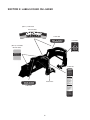
Operator’s
Manual
Front Loader w/60" Bucket
Model 59A40003727
Cub Cadet Yanmar LLC
P.O. Box 361052
Cleveland, Ohio 44136-1052
PRINTED IN U.S.A.
769-03185
(10/7/08)
Table of Contents
Content
Page
Safe Operation Practices................................................................................................................................. 3
Safety Labels found on the Loader ................................................................................................................. 6
Loader Specifications ...................................................................................................................................... 7
To the Dealer.................................................................................................................................................... 8
To the Owner.................................................................................................................................................... 8
Contents .......................................................................................................................................................... 8
Unpacking the Loader ..................................................................................................................................... 9
Initial Installation . ............................................................................................................................................ 10
Dismounting and Mounting the Loader ........................................................................................................... 15
Operation.......................................................................................................................................................... 17
Maintenance..................................................................................................................................................... 23
Troubleshooting................................................................................................................................................ 24
Parts List ......................................................................................................................................................... 26
Finding Model Number
This Operator’s Manual is an important part of your new front-end loader. It will help you assemble, prepare and maintain the unit for best
performance. Please read and understand what it says.
Before you start assembling your new equipment, please locate the model plate on the equipment and copy the information
from it in the space provided below. The information on the model plate is very important if you need help from our Customer
Support Department or an authorized dealer.
• You can locate the model number by looking on the loaders left-hand mast assembly. A sample model plate is shown below. For
future reference, please copy the model number and the serial number of the equipment in the space below.
Model Number
xxxxxxxxxxxxx
Serial Number
xxxxxxxxxxxxx
Cub Cadet/YanmarLLC
P.O. Box 361052
CLEVELAND, OHIO 44136
Copy the model number here:
Copy the serial number here:
www.cubcadetyanmar.com
Dealer Locator Phone Number: 877-282-5055
Calling Customer Support
If you have difficulty with this front-end loader; have any questions regarding the controls, operation or maintenance of this equipment; or
desire additional information not found in this manual, contact your nearest authorized Cub Cadet Yanmar dealer. If you need assistance
in locating a dealer in your area, contact the Customer Dealer Referral Line.
Call 1-(877) 282-5055 to reach the Customer Dealer Referral Line. Please have your unit’s model number and serial number ready when
you call. See previous section to locate this information. For more details about your unit, visit our website at www.cubcadetyanmar.com.
2
section 1: safe operation practices
Warning: This symbol points out important safety instructions which, if not followed, could endanger the personal safety
and/or property of yourself and others. Read and follow all instructions in this manual before attempting to operate this
machine. Failure to comply with these instructions may result in personal injury. When you see this symbol—HEED ITS
WARNING.
Danger: This machine was built to be operated according to the rules for safe operation in this manual. As with any type
of power equipment, carelessness or error on the part of the operator can result in serious injury. Failure to observe the
following safety instructions could result in serious injury or death.
TRAINING
PREPARATION
1. Safety instructions are important! Read this manual and the
tractor’s Operator’s Manual; follow all safety rules and safety
label information. (Replacement labels are available through
your Cub Cadet Yanmar dealer.) Failure to follow instructions
or safety rules can result in serious injury or death.
1. Check that all hardware is tight and properly installed. Always
tighten to torque specifications as instructed in this manual.
2. Air in hydraulic systems can cause erratic operation and
allows loads or equipment components to drop unexpectedly.
3. Before operating or allowing anyone to approach the equipment, purge any air in the system by operating all hydraulic
functions several times after connecting equipment, connecting hoses, or doing any hydraulic maintenance.
2. If you do not understand any part of this manual and need
assistance, contact your Cub Cadet Yanmar dealer.
3. Know your controls and how to stop engine and attachment
quickly in an emergency.
4. After connecting hoses, check that all control lever positions
function as Instructed in this Operator’s Manual. Do not operate until control lever and equipment movements are correct.
4. Operators must be instructed in and be capable of the safe
operation of the equipment, its attachments and all controls.
Do not allow anyone to operate this equipment without proper
instructions.
5. Protective sleeves must be over hydraulic hoses and securely
fastened onto metal hose fittings as described in this manual.
Replace if damaged or if protective sleeve is not properly
positioned or secured.
5. Keep hands and body away from pressurized lines. Use paper
or cardboard, not body parts to check for leaks. Wear safety
goggles. Hydraulic fluid under pressure can easily penetrate
skin and will cause serious injury or death.
6. Make sure all hydraulic hoses, fittings and valves are in good
condition and not leaking before starting power unit or using
equipment. Check and route hoses carefully to prevent damage. Hoses must not be twisted, bent sharply, kinked, frayed,
pinched, or come into contact with any moving parts. Operate
moveable components through full operational range to check
clearances. Replace any damaged hoses immediately.
6. Make sure that all operating and service personnel know
that in the event hydraulic fluid penetrates skin, it must be
surgically removed as soon as possible by a doctor familiar
with this form of injury, or gangrene, serious injury or death
will result. CONTACT A PHYSICIAN IMMEDIATELY IF FLUID
ENTERS SKIN OR EYES. DO NOT DELAY.
7. Always wear relatively tight and belted clothing to avoid
entanglement in moving parts. Wear sturdy, rough-soled work
shoes and protective equipment for eyes, hair, hands, hearing
and head.
7. Do not allow children or untrained persons to operate equipment.
INSTALLATION
8. Avoid injury or death. Never work under a raised loader.
Always lower loader to the ground with bucket or loader
attachment in full roll-back position. Operate valve levers
to release any hydraulic pressure. If loader obstructs tractor
maintenance, loader must be removed from tractor.
1. During installation, the tractor engine should be off, the key
removed and the parking brake engaged.
2. Do not disconnect hydraulic lines until attachments are
removed or lowered to the ground and system pressure is released by operating valve levers. Never operate any hydraulic
cylinders during any phase of the installation process.
9. Do not modify or alter or permit anyone else to modify or alter
the equipment or any of its components in any way.
3. After connecting hoses, check that all control lever positions
function as instructed in this Operator’s Manual. Do not operate until control lever and equipment movements are correct.
3
10.Your Cub Cadet Yanmar dealer can supply original equipment
hydraulic accessories and repair parts. Substitute parts
may not meet original equipment specifications and may be
dangerous.
17.Stop the loader arms gradually when lowering or lifting.
11.Ensure implement is properly attached, adjusted and in good
operating condition.
• Move and turn tractor at low speeds.
18.Use caution when handling loose or shiftable loads.
Avoid Injury or Death from Rollover Accidents:
• Watch for hidden hazards such as holes, ditches, and other
obstructions which may cause tractor and loader to tip over.
12.Power unit must be equipped with ROPS or ROPS CAB and
seat belt. Keep seat belt securely fastened. Falling off power
unit can result in death from being run over or crushed. Keep
foldable ROPS systems in locked up position at all times.
• Carry loads close to the ground to aid visibility and lower
center of gravity for improved stability.
• Balance loads so weight is evenly distributed and load is
stable.
13.Ensure all safety labels are installed. Replace if damaged.
(See Safety Labels later in this section).
• Be extra careful when operating on a slope.
14.Ensure shields and guards are properly installed and in good
condition. Replace if damaged.
• Do not operate on steep slopes.
• Do not stop, start or change directions suddenly on slopes.
OPERATIONAL
• If loader is equipped with round bale attachments, always
approach bale with tractor facing uphill.
1. Do not allow other people in the area when operating, attaching, removing, assembling or servicing equipment.
• Tractor must be equipped with a Roll-Over Protective
Structure (ROPS) and seat belt.
2. Improper use of a loader can cause injury or death.
• Keep seat belt securely fastened and keep foldable ROPS
systems in “locked up” position at all times.
3. Consult local utilities before working. Know location of and
avoid contacting all underground cables, pipelines, overhead
wires and other hazards in working area.
Avoid Injury or Death from Power Lines
4. Do not attempt to lift loads in excess of the loader capacity.
5. Keep bystanders away from equipment.
• Stay away from power lines. Electrocution can occur without
direct contact.
6. Do not walk or work under a raised loader, bucket or attachment.
• Check clearances before raising loader.
7. Never allow anyone to get under the loader bucket or reach
through the lift arms when the bucket is raised.
• Consult local utilities before digging. Know location of and
avoid contacting all underground cables, pipelines, overhead
wires and other hazards in digging area.
8. Do not operate equipment while under the influence of alcohol
or drugs.
• Do not leave the operator’s seat if any part of the tractor or
loader contacts electric lines or underground cables.
9. Operate only in daylight or good artificial light.
Avoid Injury or Death from Falling Objects:
10.Always comply with all state and local lighting and marking
requirements.
• This loader is not equipped with any method to prevent
objects such as round bales, posts, logs, etc. from rolling
back onto operator.
11.Do not allow riders. Do not lift or carry anybody on the loader
or in the bucket or attachments.
• Do not carry large objects that can fall out of loader bucket
into operator zone.
12.Power unit must be equipped with ROPS or ROPS CAB and
seat belt. Keep seat belt securely fastened. Falling off power
unit can result in death from being run over or crushed. Keep
foldable ROPS systems in “locked up” position at all times.
• Never lift loader higher than necessary to clear the ground
when moving.
• Before dismounting tractor or performing any service or
maintenance, disengage the power to the implement, lower
the 3-point hitch and all raised components to the ground,
operate valve lever to release any hydraulic pressure, stop
engine, set parking brake, remove key, and unfasten seat belt.
13.Always sit in tractor seat when operating controls or starting
engine. Securely fasten seat belt, place transmission in
neutral, engage brake and ensure all other controls are
disengaged before starting tractor engine.
14.Look down and to the rear and make sure area is clear before
operating in reverse.
• Never work under a raised loader. Always lower loader to the
ground with bucket or loader attachment in full roll-back position. Shut off tractor, set park brake and remove key. Operate
valve levers to release any hydraulic pressure. If loader
obstructs tractor maintenance, loader must be removed from
tractor.
15.Avoid loose fill, rocks and holes. They can be dangerous for
loader operation or movement.
16.Allow for loader length and width when making turns.
4
MAINTENANCE
9. Ensure all safety labels are installed. Replace if damaged.
(See Safety Labels later in this section)
1. Before dismounting tractor or performing any service or
maintenance, disengage power to implement, lower the 3point hitch and all raised components to the ground, operate
valve levers to release any hydraulic pressure, stop engine,
set parking brake, remove key, and unfasten seat belt.
10.Ensure shields and guards are properly installed and in good
condition. Replace if damaged.
11.Do not disconnect hydraulic lines until all system pressure is
relieved. Lower unit to ground, stop engine, and operate all
hydraulic control levers.
2. Never work under a raised loader. Always lower loader to the
ground with bucket or loader attachment in full roll-back position. Shut off tractor, set park brake and remove key. Operate
valve levers to release any hydraulic pressure.
12.When servicing or replacing pins in cylinder ends, buckets,
etc., always use a brass drift and hammer. Failure to do so
could result in injury from flying metal fragments.
3. Adjustment of system relief pressure should be done by a
qualified, experienced Cub Cadet Yanmar dealer. Incorrect
adjustment can result in system failures and serious personal
injury.
STORAGE
Block equipment securely for storage. Stored loader can fall and
cause serious injury or death. Securely store loader and attachments to prevent falling. To help prevent injury caused by a falling
implement, always:
4. Always wear relatively tight and belted clothing to avoid
entanglement in moving parts. Wear sturdy, rough-soled work
shoes and protective equipment for eyes, hair, hands, hearing
and head.
1. Detach on a hard, level surface.
2. Keep children and bystanders away
.5 Do not allow other people in the area when operating, attaching, removing, assembling or servicing equipment.
3. Engage the tractor’s parking brake before detaching from
storage area.
6. Ensure implement is properly attached, adjusted and in good
operating condition.
To provide necessary balance, loader frame must be equipped
with bucket or attachment before attaching or detaching from
tractor, or when loader is in stored position.
7. Keep all persons away from operator control area while
performing adjustments, service or maintenance.
1. Do not loosen hydraulic fittings or hoses while loader is in
stored position.
8. Tighten all bolts, nuts and screws securely. Check that all
cotter pins are installed securely to ensure equipment is in a
safe condition before operating.
2. Do not climb or lean on equipment stored on stand.
Warning! Your Responsibility
Restrict the use of this attachment to persons who read, understand and follow the warnings and instructions in this manual,
the tractor’s Operator’s Manual and on the tractor and loader attachment. The safety labels found on the loader attachment
are illustrated on the following page.
5
Section 2: labels found on loader
(QTY 2) 777D11290
On Both Sides
777D11356
777I22804
FLOAT
DOWN &
CURL
(QTY 2) 777I22850
3
DOWN &
DUMP
DOWN
1 CURL
On Both Sides
N
DUMP 2
UP
UP &
CURL
4
UP &
DUMP
READ OPERATORS MANUAL BEFORE OPERATING
BUCKET LEVEL
REFERENCE POINT
777S32188
WARNING
1. read and undersTand
operaTor's Manual
before operaTing.
2. keep oTHers aWaY WHen
operaTing loader.
3. do noT alloW CHildren
or unTrained persons
To operaTe eQuipMenT.
4. loWer loader To ground,
sTop engine, seT park
brake and reMove keY before
leaving TraCTor seaT.
5. failure To folloW safeTY
rules Can resulT in
serious inJurY or deaTH.
INSTRUCTIONS
ASSEMBLY FOR FRONT END LOADER
Model Plate
1. park loader on firM
level ground.
2. sloWlY drive THe TraCTor
Close To THe loader. sTop
and seT THe parking brake.
3. ConneCT Color Coded
HYdrauliC QuiCk disConneCT
To loader Hoses.
4. use THe loWer booM
ConTrol To loWer MasTs
onTo reCeivers.
5. ConTinue To loWer booM
unTil all WeigHT is off
THe fronT Tires.
6. loCk loader MounTing
Tube inTo reCeiver WiTH
lYnCH pins.
7. add Hair-pins To lYnCH
pins (iMporTanT To prevenT
lYnCH pin loss).
DISASSEMBLY FOR FRONT END LOADER
1. park TraCTor on firM
level ground.
2. use THe loWer booM
ConTrol To Take all
WeigHT off of fronT Tires.
3. reMove lYnCH pins froM
fronT MounT asseMblY.
4. use THe raise booM
ConTrol unTil MasTs eXiT
THeir reCeivers.
5. disConneCT THe Color
Coded HYdrauliC QuiCk
disConneCTs.
6. sloWlY drive aWaY froM
loader.
777D11357
IMPORTANT
To prevenT possible
TransMission daMage, engage
THe 4Wd onlY WHen addiTional
TraCTion is needed WHile
operaTing in loose soil or on
slipperY surfaCes (e.g. Mud,
snoW), or WHen desCending a
slope. disengage THe 4Wd
WHen operaTing on firM, flaT
surfaCes or WHen operaTing
aT HigH speeds.
6
section 3: model 59A40003727 loader specifications
A Maximum Lift Height................................................................................................... 96”
B Clearance With Attachment Dumped..........................................................................
77”
C Reach At Maximum Height.........................................................................................
26”
D Maximum Dump Angle................................................................................................
45°
E Reach With Attachment On Ground...........................................................................
67”
F Attachment Rollback Angle.........................................................................................
25°
G Digging Depth.............................................................................................................
4”
Overall Height In Carrying Position.............................................................................
54”
Length Of Attachment.................................................................................................
18.06”
Lift Capacity To Full Height.........................................................................................
900 lbs.
Breakout Capacity.......................................................................................................
2500 lbs.
System Pressure Tested.............................................................................................
1900 PSI
Recommended Hydraulic Flow...................................................................................
4-7 GPM
Lift Cylinder Bore.........................................................................................................
1-5/8”
Bucket Cylinder Bore..................................................................................................
2”
Hose Working Pressure..............................................................................................
3000 PSI
Bucket
60”
Bucket Capacity
9.0 cu. ft.
Weight
210 lbs.
d
C
a
b
f
g
e
7
Section 4: TO THE dealer
Assembly and proper installation of this attachment is the responsibility of the Cub Cadet Yanmar dealer. Read the instructions and safety
precautions found in this manual carefully. Any and all front-end attachments installed on the tractor must first be removed in order to
properly install the Front-end Loader.
Section 5: TO THE OWNER
Model 59A40003727 Front-end Loader is designed for use only with specific Cub Cadet Yanmar tractor models. It will NOT fit nor
operate safely or properly on or with any other tractor.
References to LEFT and RIGHT indicate the left and right sides of the tractor when facing forward in the operator’s position. Reference to
the FRONT indicates the grille end; to the REAR the drawbar end.
Section 6: contents
The front loader attachment components are listed below along with their part numbers. Assemblies are made up of more than one part
and do not have a part number. Before beginning installation, lay all components out on a flat surface to assure everything is present.
Throughout the manual the parts in the hardware pack will be identified by name, followed by their callout number in parenthesis, to aid in
installation.
1
3
4
2
5
6
9
7
8
10
Figure 1
1. RH Mount ........................................................... 603-04404
1 pc
2. LH Mount ........................................................... 603-04403
1 pc
3. Front Mount Receiver ...................................... 603-04402
1 pc
4. Hx. Cp. Screw, M16-2.0 x 60 ..........................710-04700
6 pc
5. Hex Cap Screw, M16-2.0 x 100 ...................... 710-04701
4 pc
6. Hex Cap Screw, 1/2-13 x 1.75 GR5 ................710-3067
8 pc
7. Flat Washer .......................................................736-0192
8 pc
8. Hex Lock Nut, 1/2-16 GR5 ..............................712-3083
8 pc
9. Mounting Pin .................................................... 711-04771A
2 pc
10. Klik Pin ............................................................ 714-0143
2 pc
Not Shown - Loader Bucket ................................. 603-04399
1 pc
Not Shown - Complete Mast & Boom Assembly N /A
1 pc
8
Section 7: unpacking the loader
Bucket
Assembly
Boom & Mast
Assembly
RH Mount
LH Mount
Loader Hitch
Bracket
Front Mount Receiver/
Mounting & Lynch Pins
Figure 2
Move the tractor and front loader to an area large enough to accommodate both, and with access to an overhead lift. To uncrate
the loader and all components, refer to Figure 2 and proceed as
follows:
• Carefully remove the top and sides of the shipping crate and
carefully cut off the plastic wrapping.
If Using an Overhead Lift
IMPORTANT: When positioning the lifting devices, use care to
avoid damage to the hydraulic lines, while also maintaining the
balance of the boom and mast assembly.
If using lift straps and an overhead lift, position the straps around
the boom and mast assembly so that the assembly is balanced
when lifted from the shipping pallet.
• Carefully lift the boom and mast assembly off the shipping
pallet.
• Remove the hardware pack from the shipping pallet. Check
the contents of the hardware pack against the list on page 8.
• Carefully remove and discard any banding wire, clamps, or
screws securing the loader bucket, RH and LH mounts, front
mount receiver, and the boom and mast assembly to the
shipping pallet.
• Remove the loader bucket from the pallet, and roll the bucket
so that it sits on its bottom surface.
• Remove the front mount receiver from the shipping pallet.
Remove the two lynch pins and withdraw the mounting pins
from the front mount receiver. Temporarily set aside the front
mount receiver and pins.
If an Overhead Lift is Not Available
• Remove the RH and LH mount assemblies from the pallet and
set aside.
• With the aid of at least one assistant, carefully maneuver the
boom and mast assembly off the shipping pallet.
IMPORTANT: Usage of an overhead lift apparatus is strongly
recommended to support and lift the boom and mast assembly
when performing the initial installation of the front loader. If an
overhead lift is not available, the aid of at least one assistant will
be necessary.
Carefully cut the shipping tie securing the free ends of the loader
hydraulic hoses to the right end of the loader hitch bracket.
Remove the packaging material from the hydraulic fittings on the
ends of the hoses.
• With the aid of at least one assistant, carefully slide the loader
bucket out from between the loader masts, and roll the bucket
so that it sits on its bottom surface.
9
Section 8: Initial Installation
Tractor Preparation
• From the left side of the tractor, locate the mounting holes and
remove the protective plugs.
Remove the front weight bracket from the front of the tractor by removing the six hex screws and nuts securing it to the front frame.
Store the front weight bracket for reinstallation when removing the
loader and attaching rear mounted equipment.
• Lift the LH mount (2) and carefully place against the tractor,
aligning its holes with the holes in the tractors clutch housing
and frame.
• Insert three hex cap screws (5) through the LH mount and
thread into the clutch housing. Insert two hex cap screws (6)
through the front of the mount and thread into the frame. In a
staggered pattern, evenly tighten all hex cap screws to secure
the LH mount. Torque the screws to 145 - 167 ft. lbs. (196-225
N•M). Refer to Figure 3.
Installing the LH and RH Mounts
IMPORTANT: The LH and RH mounts are heavy and awkward
to handle. Usage of a lifting device (e.g. floor jack), or the aid of
an assistant, while positioning the tower mounts for installation is
recommended.
Install the RH and LH mounts as follows:
• Look at the RH mount (1) to note the configuration of the
holes on the mounting plate of the assembly.
Installing the Front Mount Receiver
If not already done, remove the two lynch pins and withdraw the
mounting pins to separate the front mount receiver from the loader
hitch bracket (Refer to Figure 1).
• Slide a flat washer (8) onto each of the eight hex cap screws
(7). Refer to Figure 4.
• From the right side of the tractor, locate the three holes in a
triangular pattern on the tractor’s clutch housing, and the two
vertical holes on the front frame. Remove the protective plugs
from the holes See Figure 3.
• Position the front mount receiver (3) so that its open channel
is facing downward. Then place the front mount receiver
against the front of the tractor frame (where the front weight
bracket was previously removed).
RH Mount
Hex Cap
Screw
• Align the eight holes in the front mount receiver with the
corresponding holes in the front frame. While holding the
front mount receiver in position, insert eight hex cap screws
w/washers through the front mount receiver and tractor frame.
See Figure 4.
Clutch
Housing
Hex Cap
Screw
Front
Frame
Hex Lock Nut
Front Mount
Receiver
Figure 3
IMPORTANT: When positioning the RH mount on the tractor,
be especially careful to avoid damaging the small hydraulic lines
running along the bottom of the frame. Temporarily move the
rubber hose out of the way.
• Lift the RH mount (1) and carefully place against the tractor,
aligning its holes with the holes in the tractors clutch housing
and frame.
Hex Cap
Screw
Front
Frame
• Insert three hex cap screws (5) through the RH mount and
thread into the clutch housing. Insert two hex cap screws (6)
through the front of the mount and thread into the frame. In a
staggered pattern, evenly tighten the five hex cap screws to
secure the RH mount. Torque the screws to 145 - 167 ft. lbs.
(196-225 N•M). Refer to Figure 3.
Flat Washer
Figure 4
• Thread a hex lock nut (9) onto each hex cap screw. In a
staggered pattern, evenly tighten all hex cap screws and lock
nuts. Torque the fasteners to 60-70 ft. lbs. (81-94 N•M)
10
Front Loader Preparation
• Cut and remove the wire (or plastic ties) securing the bucket
cylinder to the boom arm.
Mounting the Bucket
NOTE: The pistons of the two bucket cylinders may be retracted
too far to connect the cylinders to the bucket rear mounting brackets by simply rolling back the bucket and/or manually extending
the cylinder pistons. If the cylinders cannot be connected to the
bucket now, wait until the hydraulic hoses are connected to extend
the cylinder pistons.
To attach the bucket to the boom & mast assembly, make sure the
bucket is sitting on its bottom and proceed as follows:
WARNING: Use care when working on the front
loader. Make certain the loader is adequately
supported and balanced.
• Lift the front of the bucket upward and rollback the bucket
to align the upper holes in the rear mounting brackets with
pistons of the bucket cylinders. Reinsert the two remaining
pins (one on the left and one on the right) to fasten the bucket
cylinders to the rear mounting brackets of the bucket. Secure
the pins with the two remaining screws and hex flange nuts
removed earlier.
• Remove the four pins (two on the left and two on the right)
from the rear mounting brackets of the bucket by removing
the hex flange lock nuts and screws, and withdrawing the pins
from the brackets. See Figure 5.
Hex Flange
Lock Nut
Pin
First installation of Loader
on Tractor
Hex Cap
Screw
The initial installation of the front loader onto the tractor can be
accomplished by utilizing an overhead lift (recommended), or by
pre-charging the loader hydraulic cylinders before beginning the
installation procedures.
The instructions in this sub-section apply only to the initial installation. Once the hydraulic lines and cylinders have been charged
with oil during the initial installation, the dismounting procedure
should leave the loader in position to be re-mounted.
Figure 5
• Position the bucket in front of the boom and mast assembly.
Align the bottom of the left and right hand boom arms with
the lower holes in the rear mounting brackets of the bucket.
Refer to Figure 6. NOTE: It may be necessary to manually roll
the bucket to align the boom arm and rear mounting bracket
holes.
WARNING: Some installation steps require the
tractor to be running and driven. Use caution
when completing these steps. Engage the
parking brake before dismounting the tractor.
If working with an assistant, make certain that
person is made aware that the tractor or any part
of the loader is about to be moved.
• Reinsert two pins (one on the left and one on the right) to
fasten the boom to the bucket mounting brackets. Secure the
pins with the screws and hex flange nuts removed earlier. See
Figure 6.
Using an Overhead Lift For Initial Installation
To complete the initial installation of the loader using an overhead
lift, proceed as follows:
• Using the overhead lift apparatus, raise the loader so that
the bottoms of the masts are high enough to clear the front
axle/tire of the tractor and the tubular bars of the RH and LH
loader mounts. Refer to Figure 7.
• Slowly drive the tractor forward while guiding the bottoms of
masts into the RH and LH mounts. Refer to Figure 8. Carefully
lower the overhead lift to set the notches at the bottom of the
masts partially onto the tubular bars of the mounts.
Bucket Cylinder
Pin
Hex Flange
Lock Nut
Hex Cap
Screw
RH Boom Arm
Figure 6
11
Outlet #3 (upper right) - connect the hydraulic line from the piston
ends of the boom cylinders (lower boom).
Outlet #4 (lower right) - connect the hydraulic line from the
cylinder body ends of the boom cylinders (raise boom).
Loader
Hitch Arms
Hydraulic Outlets
Base of Mast
2
1
3
4
Dump Bucket
(#2-Yellow)
Lower Boom
(#3-Blue)
LH Mount
Tubular Bar
Curl Bucket
(#1-Red)
Raise Boom
(#4-Green)
Figure 8
Figure 7
• Check for ties that may be installed end to end around both of
the boom cylinders. Cut and remove the ties if present.
• Stop the tractor engine and set the tractor’s parking brake
before leaving the operator’s seat. Proceed to “Installing the
Front Loader” in this section.
IMPORTANT: Re-start the tractor and perform the hydraulic test
described below in “Checking Implement Control Lever Operation” to assure that all implement control lever movements result
in the loader movements described. If loader movements do not
respond correctly, turn the tractor’s engine off, set the parking
brake and recheck all hydraulic connections as described above.
Loader control movements must be correct before proceeding.
Pre-Charging Cylinders for Initial Installation
If an overhead lift is not available, the front loader cylinders can be
used to position the loader for installation. To position the loader,
proceed as follows:
• Start the tractor and carefully drive the tractor to position it
along the right side of the front loader, facing in the opposite
direction of the loader.
IMPORTANT: If you were unable to connect the pistons of the
two bucket cylinders to the bucket rear mounting brackets as
instructed earlier, use the tractor’s implement control lever to
extend the pistons as needed and connect the cylinders now.
IMPORTANT: Stop the tractor engine. Set the tractor’s parking
brake before leaving the operator’s seat.
• Remove the four protective caps from the male couplers at
the free ends of the hydraulic hoses.
• Locate the color coded protective plugs in the female
hydraulic couplers on the lower right side of the tractor, just in
front of the right/rear tire. Refer to Figure 8.
• Using the color coded plugs and matching color coded
washers on the loader hoses to guide you, remove the plugs
and connect each loader hose to the appropriate hydraulic
coupler. Refer to Figure 8.
NOTE: If for any reason the color coded plugs of the outlets
and/or caps and washers of the hoses are unavailable or incorrect, follow the routing of each hydraulic hose/tube to the loader
cylinders to determine the loader connection of each hydraulic
line. Use the following information to determine the appropriate
hose to hydraulic outlet connection. Working from the right side of
the tractor, facing the hydraulic outlets, proceed as follows:
Outlet #1 (lower left) - connect the hydraulic line from the piston
ends of the bucket cylinders (roll back bucket).
Outlet #2 (upper left) - connect the hydraulic line from the cylinder
body ends of the bucket cylinders (dump bucket).
WARNING: Use extreme caution when performing the loader boom cylinder charging procedure.
NOTE: For packaging purposes the two boom cylinders are
fully collapsed. This results in the loader masts being positioned
beyond their normal vertical position, which causes the loader’s
center of gravity to be shifted rearward of normal. Consequently
the loader hitch arms may not pivot downward when initially
extending the boom cylinders pistons. When performing the
initial priming of the boom cylinders, it will be necessary to apply
downward force on the front of the bucket (e.g.; placing weight on
bucket shave plate; an assistant applying downward pressure on
the bucket) to pivot the hitch arms downward and raise the loader
masts.
• While observing the hoses to ensure they do not become
pinched or stretched, slowly and carefully move the implement control lever rearward to extent the boom cylinders. The
loader hitch arms should pivot downward toward the ground
and raise the bottoms of the masts.
12
• By SLIGHTLY moving the implement control lever in the various directions, check that all control lever positions correctly
operate the loader movements as indicated in Figure 10.
• Continue to carefully extend the boom cylinders (and roll back
the bucket if necessary) until the center points of the support
plates on the bottom of the loader hitch bracket at the front of
loader hitch arms are resting on the ground (Refer to Figure
13). The support plates and bucket should be supporting the
loader and the bottom of each mast should now be higher
than the tubular bars of the loader mounts.
IMPORTANT: Move the control lever only slightly.
• Stop the tractor engine and engage the parking brake.
Disconnect the loader hoses from the hydraulic couplers
by pushing inward the locking collars of the tractor’s female
hydraulic couplers.
• Start the tractor and drive to the rear of the front loader. Align
with the opening between the loader masts, and slowly drive
the tractor forward while guiding the bottoms of masts into
the RH and LH mounts.
Boom
Float
Lower
Boom
• Stop the tractor engine and engage the parking brake.
Dump
Bucket
Roll Back
Bucket
Checking Implement Control Lever Operation
The tractor’s implement control lever is used to control the movements of the loader. Perform the following test to make certain
that the loader hydraulic hoses and tubes are correctly connected.
All implement control lever movements should result in the loader
movements described in this sub-section.
Raise
Boom
Figure 10
• Using the color coded plugs and matching color coded
washers on the loader hoses to guide you, remove the plugs
and connect each loader hose to the appropriate hydraulic
coupler. If for any reason the color coded plugs of the outlets
and/or washers of the hoses are unavailable or incorrect,
refer to the hose routing information on page 12
• If loader movements do not respond correctly, turn the
tractor’s engine off, set the parking brake and recheck all
hydraulic connections. Loader control movements must be
correct before proceeding.
Initial Installation of Loader on Tractor
The control lever will be used to aid in mounting the loader to the
tractor. To complete the initial installation, proceed as follows:
WARNING: Always comply with all Safety Rules
before starting the tractor.
NOTE: If an overhead lift was used and the pistons of the two
bucket cylinders have not been connected to the bucket rear
mounting brackets as instructed earlier, use the tractor’s implement control lever to extend the pistons as needed to connect the
cylinders now.
• Start the tractor’s engine and operate at a low/safe RPM.
• Shift the tractor’s hydraulic lock lever to the center position.
See Figure 9 and refer to the tractor Operator’s Manual.
• If an overhead lift was used to position the loader, lower the
lift to make certain it is no longer supporting the loader. Do
not remove the attaching devices yet. Re-start the tractor
engine.
• While observing the base of the masts, slowly push the implement control lever forward to lower the boom, and to the right
to dump the bucket. Drive the tractor forward (as needed)
to settle the masts onto the tubular bars of the RH and LH
mounts. Refer to Figure 11.
Hydraulic
Lock Lever
Figure 9
13
LH Mast
Front Mount
Receiver
Mounting
Pin
LH Mount
Lynch Pin
Support
Plate
Loader Hitch
Bracket
Figure 11
• When the masts are firmly settled into the tower mounts,
continue to slowly push the control lever forward, and to the
right, to raise the loader hitch bracket upward into the front
mount receiver. As the loader hitch bracket is raised, the
boom cylinder pivot pins should also rotate back into the
notches of the RH and LH mounts. Refer to Figure 11. Drive
the tractor forward as necessary.
Hose Retainer Rod
NOTE: The loader hitch bracket must fit squarely in the front
mount receiver to allow installation of the mounting pins. If the
hitch bracket does not fit squarely in the channel of the front
receiver, loosen the hex screws and lock nuts fastening the loader
hitch bracket to the RH and LH loader hitch arms. Again, use
the implement control lever to raise the loader hitch bracket fully
upward in the front mount receiver. Re-tighten hex screws and
lock nuts to secure the loader hitch bracket.
• When the strut of the loader hitch bracket is fully up inside the
front mount receiver, re-insert the two mounting pins removed
earlier. Secure the mounting pins with the two lynch pins.
Figure 12
• Disconnect the overhead lift apparatus from the front loader.
• Using the hydraulic control lever, fully cycle all cylinders
several times to purge air from the hydraulic system. After air
has been purged from system, roll the bucket back and lower
to the ground.
• Route the hydraulic hoses forward along the inside of the RH
loader hitch arm and place the hoses between the loader arm
and the hook of the hose retainer rod; then loop the hoses
rearward and place the hoses between the RH loader mast
and the second hose retaining rod. Refer to Figure 12.
• Check the tractor’s transmission oil level as instructed in
tractor Operator’s Manual. Refill the transmission to the full
mark before operating the tractor and/or the loader. When
adding oil to the tractor transmission, always use the type of
oil specified for the tractor. NEVER MIX OIL TYPES.
14
section 9: dismounting and mounting the loader
Dismounting the Loader
• Continue raising the boom until center points of the support
plates on the bottom of the loader hitch bracket are resting
on the ground, the loader hitch arms and bucket are supporting the weight of the loader, and the bottom of the RH and
LH masts have lifted off the tubular bars of the RH and LH
mounts. Refer to Figure 13.
WARNING: A stored loader can fall and cause
serious injury or death. Securely store loader and
attachments on a hard level surface to prevent
falling.
• Stop the tractor engine and engage the parking brake.
WARNING: To provide necessary balance, the
loader bucket must be installed before attaching
or detaching from tractor, or when loader is in
stored position.
• Disconnect the loader hoses from the tractor’s hydraulic
couplers by pushing inward the locking collar on each female
coupler of the tractor. Leave the hoses in the hose retainer
rod.
IMPORTANT: The bucket must be installed to remove and
re-mount the loader.
Move the tractor and loader to a firm, level storage site.
• Re-install the protective plugs in the tractor’s hydraulic couplers, and push the protective caps onto the male couplers of
the loader hoses.
• Using the implement control lever, level the bucket and lower
it to the ground to take the weight off the mounting pins
securing the loader hitch bracket in the front mount receiver.
Set the tractor’s parking brake.
• Re-install the mounting pins in the front mount receiver and
secure with the two lynch pins.
• Re-start the tractor and carefully back the tractor away from
the front loader.
• Remove the two lynch pins and withdraw the two mounting
pins that secure the loader hitch bracket in the front receiver.
Refer to Figure 13.
WARNING: Do not climb or lean on the loader
while it’s in a stored position. Keep children and
bystanders away from the stored loader.
• Carefully use the control lever to raise the boom and lower the
loader hitch bracket out of the front receiver.
LH Mast
Front Mount
Receiver
Mounting
Pin
LH Mount
Lynch Pin
Loader Hitch
Bracket
Center of
Support
Plate
Figure 13
15
Mounting the Loader
• Re-start the tractor engine.
With completion of the initial installation and operation, all loader
cylinders should be filled with hydraulic oil and should maintain the
position of the boom and mast when dismounted.
NOTE: If the loader is in storage for an extended period of time,
it may become necessary to again raise the base of the masts to
re-mount the loader. If this occurs, drive the tractor along the right
side of the loader, connect the loader hoses, and use the control
lever to raise the masts as described in “Pre-Charging Cylinders
for Initial Installation” earlier in this manual.
Mount the loader as follows:
• Start the tractor; then carefully drive the tractor between the
masts, loader hitch arms, and boom assembly. Slowly drive
the tractor forward while guiding the base of each mast into
the RH and LH mounts.
• While observing the base of the masts, slowly push the implement control lever forward to lower the boom and to the right
to dump the bucket. Drive the tractor forward (as needed)
to settle the masts onto the tubular bars of the RH and LH
mounts.
• When the masts are firmly settled into the RH and LH mounts,
continue to slowly push the control lever forward, and/or to
the right, to raise the loader hitch bracket upward into the
front mount receiver. As the hitch bracket is raised, the boom
cylinder pivot pins should also rotate back into the notches of
the RH and LH mounts. Refer to Figure 11. Drive the tractor
forward as necessary.
• When the loader hitch bracket is fully up inside the front
mount receiver, re-insert the two mounting pins removed
earlier. Secure the mounting pins with the two lynch pins.
• Stop the tractor engine and engage the parking brake.
• Place the hydraulic hoses in the hose retainer rod on the RH
loader hitch arm if not already in the retainer.
• Remove the two lynch pins and withdraw the mounting pins
from the front mount receiver. Refer to Figure 11.
• Use the implement control lever to raise the bucket off the
ground.
• Using the color coded plugs and matching color coded
washers on the loader hoses to guide you, remove the plugs
and connect each loader hose to the appropriate hydraulic
coupler.
16
section 10: operation
Pre-Operation Check List
(Operator’s Responsibility)
added to your tires, and for any special maintenance
instructions after the procedure is performed.
The operator should perform the following check list
before operating loader.
• Review and follow all safety rules and safety labels
on pages 3 through 5.
• Check that all safety labels are installed and in
good condition. Replace if damaged.
• Check that equipment is properly and securely
attached to tractor, and that the bucket is securely
attached to the loader using the pins and retaining hardware supplied. Check that all hardware
(including all screws, nuts and pins) are properly
installed and secured.
• Check all lubrication points and grease as instructed on Page 23 of this manual.
• Check that all hydraulic hoses and fittings are in
good condition and not leaking before starting
tractor. Check that hoses are not twisted, bent
sharply, kinked, frayed or pulled tight. Replace any
damaged hoses immediately.
• Make sure tractor ROPS and seat belt are in good
condition. Never operate the loader without the
tractor ROPS installed and in the up position, and
the seat belt securely fastened around you lap.
• Do NOT allow riders.
Using implement control lever
The tractor’s implement control lever is located at the
front/right corner of the operator’s seat and is used
to control the movements of the loader. All implement
control lever movements should result in the loader
movements described below. If loader movements
do not respond correctly, turn the tractor’s engine
off, set the parking brake and recheck all hydraulic
connections as described in “Pre-Charging Cylinders
for Initial Installation” in the “Initial Installation” section
earlier in this manual.
While seated in the operator’s seat of the tractor,
use the implement control lever to control the loader
movements as follows (Refer to Figure 14):
• Move the control lever rearward to raise the loader
boom.
• Move the control lever to the right to dump bucket.
• Move the control lever to the left to roll back
bucket.
• Move the control lever rearward and to the right to
raise the boom and dump the bucket.
• Move the control lever rearward and to the left to
raise the boom and roll back the bucket.
• Move the control lever forward to lower the loader
boom.
• Move the control lever forward and to the right to
lower the boom and dump the bucket.
• Move the control lever forward and to the left to
lower the boom and roll back the bucket.
• Move the control lever fully forward past the
detent to place the boom in the float position. The
boom will float and allow the bucket will follow the
contour of the ground. The bucket control cannot
be used when the lever is in the float position.
Tractor Ballast
If installing only the front loader (without the backhoe),
weight must be added to the rear of the tractor. The
most common methods of adding weight are mounting
the rear weight box (Mod. No. 59A40013727) and/or
filling the rear wheels with liquid ballast.
Rear Weight Box
Requires a minimum total weight of 500 pounds in
a rear weight box, with the center of gravity of the
weight positioned approximately 41" from the center
of rear axle and 20" above ground. If the weight box
is positioned closer to the rear axle or carried higher,
additional weight must be added to effectively counterbalance the front loader.
Boom
Float
Lower/
Roll Back
Liquid Ballast
A water solution of calcium chloride may be used
as liquid ballast in each rear tire. Refer to the tractor
operator’s manual for information on adding liquid
ballast to the rear tires. Liquid ballast alone may not
provide adequate counterbalance to the front loader.
Because special equipment and a familiarity with the
practice is required, only a qualified tire technician
should perform this procedure. Consult with your
Cub Cadet Yanmar dealer about having liquid ballast
Lower
Boom
Dump
Bucket
Roll Back
Bucket
Raise/
Roll Back
Raise
Boom
Figure 14
17
Lower/
Dump
Raise/
Dump
Operating the Loader
NOTE: Do not be concerned if the bucket is not
completely filled during each pass. Maximum productivity is determined by the amount of material loaded
in a given period of time. Time is lost if two or more
attempts are made to fill the bucket on each pass.
WARNING: Do not operate unless all control lever
positions function as instructed in Figure 10.
The loader should be operated with the tractor engine
running at a safe RPM. Excessive speeds are dangerous, and may cause bucket spillage and unnecessary
strain on the tractor and loader.
Lifting the Load
When lifting the load, keep the bucket positioned to
avoid spillage. See Figure 17.
IMPORTANT: To prevent possible damage to the
tractor transmission, engage the 4WD only when
additional traction is needed while operating in loose
soil or on slippery surfaces, or when descending a
slope. Disengage the 4WD when operating on firm,
flat surfaces or when operating at high speeds. Refer
to the tractor operator’s manual for instructions on
using the 4WD feature.
• Approach and enter the pile with a level bucket.
See Figure 15.
Figure 17
WARNING: Do not attempt to lift bucket
loads in excess of the loader capacity.
Figure 15
The lift and rollback of the bucket will increase efficiency because maintaining a level bucket throughout
the lifting cycle resists bucket lift and increases
breakaway effort. See Figure 16.
IMPORTANT: If you should discover that your tractor
requires increased stability for a particular application,
contact your Cub Cadet Yanmar dealer about additional weighting for the rear of the tractor.
Carrying the Load
Correct
Position the bucket below the level of the tractor hood
for maximum stability and visibility, whether the bucket
is loaded or empty. See Figure 18.
NOT Correct
Figure 18
Figure 16
18
Dumping the Bucket
Use extreme care when operating the loader on a
slope; keep the bucket as low as possible. This keeps
the bucket and tractor center of gravity low and will
provide maximum tractor stability. See Figure 19.
Lift the bucket high enough to clear the side of the
vehicle. Move the tractor in as close as possible, then
dump the bucket. See Figure 20.
Correct
NOT Correct
Figure 20
Figure 19
Lowering the Bucket
WARNING: Avoid injury or death from
rollover accidents:
After the bucket is dumped, back away from the
vehicle while lowering and rolling back the bucket.
• Move and turn tractor at low speeds.
• Watch for hidden hazards such as holes, ditches,
and other obstructions which may cause tractor
and loader to tip over.
Lower
• Carry loads close to the ground to aid visibility and
lower center of gravity for improved stability.
• Balance loads so weight is evenly distributed and
load is stable.
• Be extra careful when operating on a slope.
• Do not operate on steep slopes.
• Do not stop, start or change directions suddenly on
slopes.
• Tractor seat belt and Roll-Over Protective Structure
(ROPS) must be present. Keep seat belt securely
fastened and keep ROPS systems in “up” position
at all times.
Roll Back
IMPORTANT: When transporting the load, keep the
bucket as low as possible to avoid tipping, in case a
wheel drops in a rut. Refer to Figure 19.
Figure 21
19
Operating with a Float Control
Peeling and Scraping
During hard surface operation, keep the bucket level
and put the lift control in the float position to permit
the bucket to float on the working surface. If hydraulic
down pressure is exerted on the bucket, it will wear
faster than normal. See Figure 22.
Use a slight bucket angle, travel forward, and hold
the lift control forward to start the cut. Make a five- to
eight-inch angle cut and break-out cleanly. See Figure
24.
Surface Material
Figure 22
Figure 24
NOTE: The float will also prevent the mixing of surface
material with stockpile material. The float position will
reduce the chance of surface gouging when removing
snow or other material.
With the bucket level, start a cut at the notch approximately four inches deep. Hold the depth by feathering
the bucket control to adjust the cutting lip up or down.
When the front tires enter the notch, adjust the lift
cylinder to maintain proper depth. See Figure 25.
Loading from a Bank
Exercise caution when undercutting high banks. Dirt
slides can be dangerous. Load from as low as possible for maximum efficiency. Loader lift and break-away
capacity diminish as loading height is increased.
It’s important to keep the bucket level when approaching a bank or pile. This will help prevent gouging in the
work area. See Figure 23.
Figure 25
Make additional passes until the desired depth is
reached. During each pass, only use the bucket
control while at working depth. This will allow you to
concentrate on controlling the bucket angle to maintain a precise cut.
Figure 23
20
Loading Low Trucks or Spreaders from a Pile
Backblading
For easier loading, minimize the angle of turn and
length of run between pile and spreader. See Figure
26.
Position the bucket at an angle of less than 45º and
backup slowly. See Figure 28
Backgrading or backblading with bucket tilted too far
will result in damage to tilt cylinders and void warranty.
See Figure 28.
Correct
NOT Correct
Figure 26
Backgrading
Backgrade occasionally with a loaded bucket to keep
the working surface free of ruts and holes. Also, hold
the control lever forward so the full weight of the
bucket is scraping the ground. Use the heel of the
bucket. See Figure 27.
Figure 28
Figure 27
21
Backfilling
Handling Objects
Approach the pile with a flat bucket. Do not use
the bucket in the dump position for bulldozing. This
method will impose severe shock loadings on the
dump linkage, the tilt cylinder, and the tractor. Refer to
Figure 29.
WARNING: Avoid injury or death from
falling objects. This loader is not
equipped with any method to prevent
objects such as round bales, posts,
logs, etc. from rolling back onto operator.
• Leave dirt in the bucket because dumping on each
pass wastes time.
• Operate at right angles to the ditch. Take as big
a bite as the tractor can handle without lugging
down.
WARNING: Do not carry large objects
that can fall out of loader bucket into
operator zone.
• Leave dirt which drifts over the side of the bucket
for final clean-up.
WARNING: Never lift loader higher than
necessary to clear the ground when
moving.
• Pile dirt on the high side for easier backfilling on a
slope.
Correct
NOT Correct
Figure 29
22
Section 11: maintenance
Lubrication
- Apply lubrication to the grease fittings at the
each end of both boom lift cylinders.
Daily
- Apply lubrication to the grease fitting in the hub
at the upper end of each bucket cylinder.
• Check the level of hydraulic oil in tractor before
starting each day’s operation. If necessary, add oil
as recommended in your tractor owner’s manual.
- Apply lubrication to the grease fittings in the
outer end of all four pivot pins of the loader
bucket.
IMPORTANT: When adding oil to the tractor reservoir,
always use hydraulic oil as specified in the tractor
operator’s manual.
General Maintenance
After every eight hours of operation, check all hardware and tighten where required.
• Lubricate after every eight hours of operation (See
Figure 30):
Replace hoses immediately if they are damaged by
a cut or scrape, extruded at the fittings, or leaking.
Hydraulic oil leaks should be repaired promptly to
avoid loss of oil and serious personal injury from
escaping oil.
- Apply lubrication to the grease fitting in the hub
at the mast end (rearward end) of each boom
arm.
LUBRICATION
Figure 30
23
Section 12: troubleshooting
PROBLEM
Jerky Operation
Slow Operation
Oil Leaks
Cannot Raise Load
POSSIBLE CAUSE
SOLUTION
• Air in hydraulic system
• Cycle cylinders several times to
purge system of air.
• Cold hydraulic oil
• Run engine to warm oil.
• Low hydraulic oil level
• Add oil to level specified.
• Poor oil circulation
• Change oil filter and clean
screen in tractor hydraulic
system.
• Worn or damaged hydraulic pump
• Repair or replace pump.
• Air leak in pump inlet line
• Check, tighten or replace inlet
line.
• Faulty valve
• Repair or replace valve.
• Air in hydraulic system
• Cycle lift cylinders and bucket
cylinders several times to free
system from air.
• Hydraulic oil too heavy
• Change to proper oil.
• Oil filter plugged
• Clean and replace filter.
• Slow engine speed
• Increase engine speed rate.
• Cylinder piston seals leaking
• Repair (if available) or replace
• Valve out of adjustment or malfunctioning
• Adjust, repair or replace.
• Tractor hydraulic pump malfunctioning
• Repair or replace pump.
• Hydraulic couplers not completely engaged
• Connect hydraulic couplers.
• Loose hose connections
• Tighten fittings.
• Fittings or hoses defective
• Use thread sealer on pipe
(tapered) threads.
• Hydraulic cylinder seals worn or damaged
• Repair seals (if available) or
replace cylinder.
• Valve components worn or damaged
• Repair and/or replace.
• Low oil supply
• Check oil level.
• Bucket overloaded
• Try lighter load.
• Hose fittings not fully engaged in couplers
• Recouple hoses.
• Cylinder piston seal leakage
• Repair or replace.
• Valve out of adjustment or malfunctioning
• Repair or replace.
• Hydraulic pump malfunctioning
• Repair or replace.
• Load is greater than boom lift capacity
• Check loader specifications.
24
PROBLEM
Bucket or Boom Leaks
Down from “Hold”
Position
POSSIBLE CAUSE
SOLUTION
• Leaks in hydraulic circuits
• Tighten loose fittings. Use
thread sealer on pipe threads.
• Cylinder piston seals leaking
• Repair (if available) or replace.
• Remote valve worn or damaged
• Repair.
• Tractor valve worn or damaged
• Repair.
Cannot Lower Boom
• Hydraulic couplers not fully engaged.
• Recouple hoses.
Loss of Bucket Tilt
Control When Lever
is Pushed Completely
Forward
• Tractor lever in “Float” position
• Shift control lever from “Float”
position.
Couplers Hard
to Hook Up
• Pressure in circuit
• Place control levers in “Float”
when connecting.
Boom & Bucket
Operation Does Not
Correspond To Control
Lever Position
• Improperly installed hydraulic couplers
• Install hydraulic couplers
correctly.
• Hoses improperly connected
• Connect hoses properly.
Excessive Wear on
Bucket Cutting Edge
and Wear Pads
• Bucket is tilted too far forward and is riding
on cutting edge.
• Keep bottom of bucket parallel
to ground.
• Excessive down pressure when cleaning
feedlots and working on concrete.
• Use “Float” position on boom
lift control lever.
25
Section 13: Parts list
45
43
31
33
36
42
44
53
61
51
49
31
56
35
55
48
32
59
50
15
34
5
45
30
43
56
46
38
39
40
29
57
44 46
58
42
41
56
37
21
56
59
25
20
25
47
59
47
20
30
6
5
14
47
20
59
47
5
29
20
62
8
10
60
11
21
56
59
20
25
59
11
26
19
4
27
52
20
16
16
24
12
54
23
22
7
28
13
2
17
52
28
9
22
27
3
1
26
18
Parts list
Ref. Part
No. Number
Description
Ref. Part
No. Number
Qty.
Description
Qty.
1
603-04399
Bucket, Loader
1
2
603-04402
Receiver, Front Mount
1
3
603-04403
Mount, LH
1
4
603-04404
Mount, RH
1
5
603-04405
Pin, Loader
6
6
603-04407
Pin, Pivot
2
7
603-04408
Mast, Vertical Support LH
1
8
603-04409
Mast, Vertical Support RH
1
9
603-04411
Bracket, Loader Hitch
1
10
603-04431
Boom Assembly
1
11
603-04444
Pin, Hollow
4
12
703-06067
Arm, Loader Hitch LH
1
13
703-06116
Arm, Loader Hitch RH
1
14
703-06212
Bracket, Tube Cover
1
15
710-0106
Screw, Hex Cap, 1/4-20 x 1.25 Gr5
6
16
710-0376
Screw, Hex Cap, 5/16-18 x 1.0 Gr5
2
17
710-04700
Screw, Hex Cap, M16-20 x 60
6
18
710-04701
Screw, Hex Cap, M16-20 x 100
4
47
19
710-04706
Screw, Hex Cap, 5/8-11 x 1.75 Gr8
10
20
710-3005
Screw, Hex Cap, 3/8-16 x 1.25 Gr5
12
21
710-1652
Screw, Hex Wash. Hd. Tapp
1/4-20 x .625
4
22
710-3067
Screw, Hex Cap, 3/8-16 x 1.25 Gr2
16
23
711-04771A Pin, Mounting
2
24
712-04063
Nut, Hex Flange Lock, 5/16-18 GrF
2
25
712-04065
Nut, Hex Flange Insert Lock
3/8-16 GrF
12
26
712-04143
Nut, Hex Lock, 5/8-11
10
56
737-04185
Fitting, 90˚ Elbow, 3/8 x 3/8 Orb
8
27
712-3083
Nut, Hex Insert Lock, 1/2-13 GrB
16
57
737-04197
Fitting, Branch Tee, 3/8
4
28
714-0143
Pin, Klik
2
58
737-04198
Fitting, Swivel Elbow, 3/8
2
33
727-04187
727-04213
Hose, Hydraulic, 60 inch
Sleeve, Hose
4
1
34
727-04197
Cap, Coupler Protective - Green
1
35
727-04198
Cap, Coupler Protective - Blue
1
36
727-04199
Cap, Coupler Protective - Yellow
1
37
727-04200
727-3262
Cap, Coupler Protective - Red
Cap, Coupler Protective - Black.
Use in place of color coded caps
(34-37) if they are not available.
1
4
38
727-04202
Tube, Hyd., U Shape - Bckt Dump
1
39
727-04203
Tube, Hyd., U Shape - Bucket Curl
1
40
727-04204
Tube, Hyd., U Shape - Boom Raise
1
41
727-04205
Tube, Hyd., U Shape - Boom Lower
1
42
727-04206
Tube, Hydraulic - Bucket Curl RH
1
43
727-04207
Tube, Hydraulic - Bucket Dump RH
1
44
727-04208
Tube, Hydraulic - Boom Raise RH
1
45
727-04209
Tube, Hydraulic - Boom Lower RH
1
46
48
727-04211
726-0230
727-04212
726-0230
731-3374
Hose, Hydraulic, 36 inch
Tie, Cable - Tie hose to cylinders
Hose, Hydraulic, 25.5 inch
Tie, Cable - Tie hose to cylinders
Washer, Color Coded - Red
2
4
6
4
1
49
731-3375
Washer, Color Coded - Yellow
1
50
731-3376
Washer, Color Coded - Green
1
51
731-3377
Washer, Color Coded - Blue
1
52
736-0192
Washer, Flat, .535 x .93 x .09
16
53
736-0211
Washer, Flat, .285 x 1.25 x .06
6
54
736-0366
Washer, Flat, .64 x 1.12 x .125
10
55
737-04179
Fitting, Elbow, 3/8-NPTF
4
29
717-04413
Cylinder, Loader Bucket
2
59
737-3000
Fitting, Lube
12
30
717-04417
Cylinder, Boom Lift
2
60
747-04753
Rod, Hook
1
31
717-04081
Clamp, Tube
24
61
710-04729
Bolt, Stacking, 1/4-20 x 3/4
6
32
727-04183
Coupling, Mail Quick Connect
4
62
731-06400
Plug, Rectangular Tube
2
27