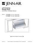
1
INSTALLATION INSTRUCTIONS
HH0005
64000 SERIES
! INTENDED FOR DOMESTIC COOKING ONLY !
READ AND SAVE THESE INSTRUCTIONS
INSTALLER: LEAVE THIS MANUAL TO HOMEOWNER.
HOMEOWNER: USE AND CARE INFORMATION ON PAGES 10 TO 12
Broan-NuTone LLC, 926 West State Street, Hartford, WI 53027 (1-800-637-1453)
NuTone Inc., 4820 Red Bank Road, Cincinnati, OH 45227 (1-800-543-8687)
Broan-NuTone Canada Inc., 1140 Tristar Drive, Mississauga, ON L5T 1H9 (1-888-882-7626)
V03515 rev G
! WARNING
! WARNING
TO REDUCE THE RISK OF FIRE, ELECTRIC
SHOCK OR INJURY TO PERSONS, OBSERVE THE
FOLLOWING:
TO REDUCE THE RISK OF INJURY TO PERSONS
IN THE EVENT OF A RANGE TOP GREASE FIRE,
OBSERVE THE FOLLOWING*:
1.
Use this unit only in the manner intended by the
manufacturer. If you have questions, contact the
manufacturer at the address or telephone
number listed in the warranty.
1.
2.
Before servicing or cleaning unit, switch power
off at service panel and lock service disconnecting
means to prevent power from being switched on
accidentally. When the service disconnecting
means cannot be locked, securely fasten a
prominent warning device, such as a tag, to the
service panel.
3.
Installation work and electrical wiring must be
done by qualified personnel in accordance
with all applicable codes and standards, including
fire-rated construction codes and standards.
4.
Sufficient air is needed for proper combustion
and exhausting of gases through the flue
(chimney) of fuel burning equipment to prevent
backdrafting. Follow the heating equipment
manufacturer’s guidelines and safety standards
such as those published by the National Fire
Protection Association (NFPA), and the
American Society for Heating, Refrigeration and
Air Conditioning Engineers (ASHRAE), and the
local code authorities.
5.
When cutting or drilling into wall or ceiling, do not
damage electrical wiring and other hidden utilities.
6.
Ducted fans must always be vented to the outdoors.
7.
Do not use this unit with any additional solid-state
speed control device.
8.
To reduce the risk of fire, use only steel ductwork.
9.
This unit must be grounded.
TO REDUCE THE RISK OF A RANGE TOP
GREASE FIRE:
a)
Never leave surface units unattended at high
settings. Boilovers cause smoking and greasy
spillovers that may ignite. Heat oils slowly on
low or medium settings.
b)
Always turn hood ON when cooking at high heat
or when cooking flaming foods.
c)
Clean ventilating fans frequently. Grease should
not be allowed to accumulate on fan or filter.
d)
Use proper pan size. Always use cookware
appropriate for the size of the surface element.
SMOTHER FLAMES with a close-fitting lid,
cookie sheet or metal tray, then turn off the
burner. BE CAREFUL TO PREVENT BURNS.
IF THE FLAMES DO NOT GO OUT IMMEDIATELY,
EVACUATE AND CALL THE FIRE DEPARTMENT.
2. NEVER PICK UP A FLAMING PAN – You may
be burned.
3. DO NOT USE WATER, including wet dishcloths or
towels – This could cause a violent steam explosion.
4. Use an extinguisher ONLY if:
A. You own a Class ABC extinguisher and you
know how to operate it.
B. The fire is small and contained in the area
where it started.
C. The fire department has been called.
D. You can fight the fire with your back to an exit.
* Based on “Kitchen Fire Safety Tips” published by
NFPA.
CAUTION
1.
For general ventilating use only. Do not use to
exhaust hazardous or explosive materials and
vapors.
2. To avoid motor bearing damage and noisy
and/or unbalanced impellers, keep drywall
spray, construction dust, etc. off power unit.
3. Your hood motor has a thermal overload which
will automatically shut off the motor if it
becomes overheated. The motor will restart
when it will be cooled down. If the motor continues
to shut off and restart, have the hood serviced.
4. For best capture of cooking impurities, the bottom
of the hood should be at a minimum of 20”
(24” over a gas range) and at a maximum of 30”
above the cooking surface.
5. Two installers are recommended because of the
large size and weight of this hood.
6. To reduce the risk of fire and to properly exhaust
air, be sure to duct air outside – Do not exhaust
air into spaces within walls or ceiling or into
attics, crawl space or garage.
7. This product is equipped with a thermostat
which may start blower automatically. To reduce
the risk of injury and to prevent power from
being switched on accidentally, switch power off
at service panel and lock or tag service panel.
8. Because of the high exhausting capacity of this
hood, you should make sure enough air is entering
the house to replace exhausted air by opening a
window close to or in the kitchen.
9. To reduce the risk of fire and electric shock, the
Rangemaster 64000 Series hood must be
installed with blower models P5, P8, 331H,
332H, 335 or 336 only. Other blowers cannot
be substituted. (Blowers sold separately.)
10. Use with approved cord-connection kit only.
11. Please read specification label on product for
further information and requirements.
-2-
64000 SERIES
RANGE HOOD
SYSTEM
Model 647
(7” Rd wall cap)
Model 634 or 644
(roof cap)
Model 643
(8” Rd wall cap)
Model 634 or 644
(roof cap)
Model 412
transition
(3 1/4” x 10” to 7”)
Model 335 (1200 cfm)
or 336 (1500 cfm)
exterior blower
Model 459 transition
(3 1/4” x 14” to 8”)
Model 418
10” Rd
adjustable elbow
8” Rd
standard
duct
Model 407
(7” Rd x
24’’ section)
Model 331H (600 cfm)
or 332H (900 cfm)
exterior blower
Model 421
(10” Rd. vert.
in-line damper)
Standard
3 1/4” x 14” duct
Model 413
transition
Standard
3 1/4” x 10” duct (3 1/4” x 10” to 8”)
Adapter and damper
3 1/4’’ x 14’’
(supplied with P8 blower)
Adapter and damper
3 1/4’’ x 10’’
(supplied with P5 and P8 blowers)
Model 410
(10” Rd duct - 2ft. sections)
Flow deviator
(vertical exhaust only)
(supplied with P5 and P8 blowers)
64000 SERIES HOOD
Model 332 KR exterior
blower rough-in kit
Rough-in kit
(supplied with P5 and P8 blowers)
Model P8 dual-blower (900 cfm)
for use with 36’’ hoods or wider
Model P5
single-blower
(500 cfm)
NOTE: The dual blower P8 can be
installed either with 3 1/4’’ x 14’’
or 3 1/4’’ x 10’’ ducts.
For optimal air and quiet sound
performance,
use 3 1/4’’x 14’’ducts.
Backsplash
(RMP Series)
HL0020
-3-
1. INSTALL DUCTWORK
2. MEASURE INSTALLATION
Plan where and how the ductwork will be installed.
Install proper-sized ductwork, elbows and roof or
wall cap for the type of blower you are installing. If
using 7” or 8” round ducts, or 3 1/4’’ x 14’’ duct, use
a transition. Use 2” duct tape to seal duct joints.
Dimensions for the most common installations are
shown below.
We recommend you to install the hood at a
minimum of 20” from an electric range and
24” from a gas range.
For optimal performance, the hood should not be
installed more than 30” from cooktop.
STANDARD INSTALLATION
Roof cap
3 1/4" x 14" to 8''
transition if
3 1/4" x 14" duct
Cabinets
3 1/4" x 10" or
3 1/4" x 14" duct
Wall
cap
Hood with
interior blower
Hood
Backsplash
(Optional)
20" minimum
clearance
(24" for gas)
HH0029A
INSTALLATION WITH 7” OR 8” ROUND DUCT
Roof cap
Standard 36" h.
cook top
7" or 8" round duct
Wall
cap
HH0004A
3 1/4" x 10"
to 7" or 8" transition
Hood with
interior blower
Cabinets
HH0015A
INSTALLATION WITH EXTERIOR BLOWER
Hood
External blower
Backsplash
(Optional)
30" maximum
clearance
External
blower
10" round duct
Standard 36" h.
cook top
Hood with
exterior blower
HH0003A
HH0016A
-4-
3. PREPARE THE INSTALLATION
Make sure that the following items are included:
- Range hood
- Accessories:
• Filters
• Bag of parts including:
(4) lock nuts, (1) wire clamp, (8) 1/2” double thread screws, (2) wire connectors,
(2) 1/2” standard screws, (6) 3/8 screws.
Parts sold separately:
- Interior blower Model P5 includes blower, rough-in kit, flow deviator and 3 1/4” x 10” adapter
- Interior blower Model P8 includes blower, rough-in kit, flow deviator and 3 1/4” x 10” adapter
and 3 1/4” x 14” adapter
- Exterior blower Model 331H, 332H, 335 or 336
- Exterior blower rough-in kit Model 332KR (required for all exterior blower models)
- Halogen lights (120V, 50W, PAR 20)
- Heat lamps (120V, IR 175W, PAR 38)
- Backsplash (optional)
- Baffle filters (optional)
- Transitions, duct, elbows, dampers, wall and roof caps. Refer to page 3 for a complete list of venting
options and model numbers.
NOTE: For cabinets with recessed bottom, attach wood filler strips (not included) on each sides, as
shown below. Use two (2) 2-inch wide strips for 30’’ wide hoods, and four (4) 2-inch wide strips for
wider hoods, cut to length. See below for wood filler strip locations.
HOOD
WIDTHS
30’’
36’’
42’’
48’’
A
2’’
2’’
2’’
4’’
LOCATIONS
B
C
N/A
N/A
4 1/2’’ 4 1/2’’
7 1/4’’ 8 1/4’’
10 1/4’’ 11 1/4’’
A
HD0079
A
B
C
4. INSTALL BACKSPLASH (OPTIONAL)
Backsplash must be installed before the hood shell because the hood shell covers the backsplash top
mounting screws. In order to be able to install the backsplash, make sure you have at least 18’’ clearance
between bottom of hood and range control panel or cooktop. (See instructions packed with backsplash.)
5. SELECT BLOWER OPTION (EXTERIOR OR INTERIOR)
INTERIOR BLOWER: Follow all subsequent steps of this manual.
EXTERIOR BLOWER: Refer to instructions packed with exterior blower and follow steps 7, 10, 13, 14
and 15 of the present manual.
-5-
6. CHOOSE THE OPENING (INTERIOR BLOWER)
Remove the knockout for the chosen opening (horizontal at the back of the hood or vertical on rough-in
plate). See pictures below.
CAUTION
When using P5 blower, remove the 10’’ wide knockout (smaller part). If using P8 blower, remove
the knockout corresponding to the ducting installed (10’’ or 14’’).
UT
CKO
NO
14’’ K
14’’ KNOCKOUT
10’’ KNOCKOUT
OUT
OCK
KN
10’’
HD0076
HD0077
Removing horizontal knockout opening on back of hood
Removing vertical knockout opening on rough-in plate
7. INSTALL THE ROUGH-IN PLATE (INTERIOR & EXTERIOR BLOWER)
INTERIOR BLOWER: Secure the rough-in plate (provided with the P5 and P8 blower) inside the hood with
four (4) lock nuts. See picture below.
HD0042
EXTERIOR BLOWER: Purchase Model 332KR separately. Refer to instructions included with the rough-in
kit. Secure the rough-in plate inside the hood with (4) lock nuts.
8. INSTALL THE DEVIATOR (INTERIOR BLOWER)
YOU MUST install the deviator if you choose to vent the hood
vertically. Install the deviator as shown.
NOTE: If installed correctly, the deviator will protrude about 1/8”
above the rough-in plate.
HD0003
-6-
Inserting deviator into hood vertical opening
9. INSTALL THE ADAPTER (INTERIOR BLOWER)
Using two (2) standard 1/2’’ screws, secure the adapter to the top (or back) of the hood. Seal the adapter
to the hood using duct tape.
HD0005
HD0006
10. INSTALL THE HOOD (INTERIOR & EXTERIOR BLOWER)
INTERIOR BLOWER: Run power cable to installation location. Place the hood to its location. Mark the position
of the screws (smaller part of the key holes) with a pen. Remove the hood and install the (8) 1/2” double
thread screws leaving a 1/8” gap (4 screws for 30” hood). Remove wiring cover, place the wire clamp, insert
the cable in the hood and tighten the wire clamp to secure the cable. Place the hood under the cabinet
and slide it in position. Make sure the adapter/damper assembly enters the ducting. Secure the hood by
tightening the screws completely.
HD0043
EXTERIOR BLOWER: Run power cable to installation location. Place the hood to its location. Mark the
position of the screws (smaller part of the key holes) with a pen. Remove the hood and install the (8) 1/2”
double thread screws leaving a 1/8” gap (4 screws for 30” hood). Remove wiring cover on top of the hood
and connect wiring (see instructions included with exterior blower). Place the hood under the cabinet and
slide it in position. Secure the hood by tightening the screws completely.
-7-
11. CONNECT WIRING (INTERIOR BLOWER)
0
! WARNING
Risk of electrical shock. Electrical wiring must be done by qualified personnel in accordance with
all applicable codes and standards. Before connecting wires, switch power off at service panel
and lock service disconnecting means to prevent power to be switched on accidentally.
Connect cable into wiring box using wire connectors.
Connect wires as follow: BLACK to BLACK, WHITE to WHITE
and GREEN wire under ground screw. Reinstall wiring cover. DO
NOT FORGET TO CONNECT THE GROUND.
HD0007
1
1) Ground screw
12. INSTALL THE BLOWER (INTERIOR BLOWER)
The blower must be installed to the rough-in plate using (4) 3/8” screws for the single blower unit and (6)
3/8” screws for the dual blower unit. Remove the cover from the blower assembly. Remove the impeller(s)
by pulling them out gently (see pictures below).
HD0022
HD0021
-8-
12. INSTALL THE BLOWER (INTERIOR BLOWER) (CONT’D)
Install screws into the location as shown in the pictures below (single blower or dual blower). Do not tighten
screws down fully, leave a 1/8” gap. Hang blower unit onto blower plate (screws through the large part of
the keyhole). Slide the blower to its position (screws in the small part of the keyhole). Tighten the screws.
HD0044
HD0044
Dual blower (P8)
Single blower (P5)
Secure the blower by installing 2 more screws into the locations shown in the pictures below (single blower
or dual blower). Reinstall impeller(s) and cover.
HD0080
HD0081
Dual blower (P8)
Single blower (P5)
FRONT
FOR DUAL BLOWER UNIT, MAKE
SURE THE IMPELLERS ARE
CORRECTLY INSTALLED, THE
HOOD WILL NOT WORK PROPERLY
IF REVERSED. Both impellers are
different in the dual blower, one
rotates clockwise and the other
counterclockwise. Each wheel and
motor have an arrow and a number
on them, you have to match them
correctly (see drawing beside).
2
1
HD0023
! WARNING
Never plug the 2-prong blower cord to the 3-prong power supply cord.
Plug the power supply to the 3-prong male connector (A)
and the blower unit into the 2-prong female receptacle
(B) inside the hood.
A
HE0003
-9-
B
13. LIGHT BULBS
This range hood uses 50W halogen lamps. (120V, 50W, PAR 20)
Install the lamps by rotating them clockwise into their socket holder.
14. HEAT LAMPS
The heat lamps required are 120V, 175W max, infrared bulbs. (120V, IR 175W, PAR 38)
You can use white halogen lights if warming shelves are not used. (120V, 90W, PAR 38)
Install the lamps by rotating them clockwise into their socket holder.
15. INSTALL FILTERS
It is recommended to install side filters first and finish with center one(s).
1.
2.
3.
4.
Insert upper end of filter into the hood (tab end).
Raise lower end toward the inside of hood.
Position lower end of filter into channel and pull.
While pulling the filter, slide it under the inner retaining piece.
Baffle filters are available as an option (see instruction sheet included with baffle filters).
HD0009
HD0010
16. USE AND CARE
Grease filters and impeller(s).
The grease filters, impeller(s) and grease rail should be cleaned frequently. Use a warm detergent
solution. Grease filters and impeller are dishwasher safe.
Remove filters by pushing filters towards the back of hood and rotating filters downward.
- 10 -
16. USE AND CARE (CONT’D)
Hood cleaning
Stainless steel cleaning: How to maintain its « BRIGHT LOOK »
Do:
- Regularly wash surfaces with clean cloth or rag soaked with warm water and mild soap or liquid
dish detergent.
- Always clean in the direction of original polish lines.
- Always rinse well with clear water (2 or 3 times) after cleaning. Wipe dry completely.
- You may also use a specialized household stainless steel cleaner.
Don’t:
- Do not use any steel or stainless steel wool or any other scrapers to remove stubborn dirt.
- Do not use any harsh or abrasive cleansers.
- Do not allow dirt to accumulate.
- Do not let plaster dust or any other construction residues reach the hood. During construction or
renovation, cover the hood to make sure no dust sticks to stainless steel surface.
Avoid: when choosing a detergent
- Any cleaners that contain bleach will attack stainless steel.
- Any products containing : chloride, fluoride, iodide, bromide will deteriorate surfaces rapidly.
- Any combustible products used for cleaning such as acetone, alcohol, ether, benzol, etc., are
highly explosive and should never be used close to a range.
Enamel finish:
Clean with warm water and mild detergent only. When discoloration occurs, use a good enamel polish
such as automotive polish. (DO NOT use rough abrasive cleaner or porcelain cleaner.)
17. OPERATION
Always turn your hood on before you begin cooking to establish an air flow in the kitchen. Let the blower
run for a few minutes to clear the air after you turn off the range. This will help keep the whole kitchen cleaner
and brighter.
1
1
HD0013
2
3
4
1) Warming lamp switches
2) Halogen light switches
3) ON/OFF blower switch
4) Blower speed control
BLOWER
The blower is operated using two (2) controls.
Use the red, lighted on/off switch to start and stop the blower. When turned on, the blower will operate at
the previous setting of the speed control.
Turn the speed control knob clockwise to decrease blower speed – counterclockwise to increase speed.
COOKTOP LIGHTING (HALOGEN)
A double set of ON/OFF switches controls the halogen lights.
The front rocker controls the center light (for 42” and 48” hoods). The rear rocker controls both side lights
(each switch controls one light for 30” and 36” hood). Select one, two or three lights for best cooking lighting.
Use PAR 20, 50W halogen bulbs.
- 11 -
17. OPERATION (CONT’D)
0
! WARNING
Never place highly flammable material under warming lamps.
WARMING LAMPS (INFRARED)
Each warming lamp is controlled with its own ON/OFF switch.
Use infrared light bulbs (120V, IR175W, PAR38) or white halogen bulbs (120V, 90W, PAR38) if food warming
shelves are not used.
HEAT SENTRY™
This hood is equipped with a Heat Sentry™ thermostat. This thermostat is a device that will turn on or
speed up the blower if it senses excessive heat above the cooking surface.
1) If blower is OFF - it turns blower ON to HIGH speed.
2) If blower is ON at a lower speed setting – it turns the blower up to HIGH speed.
! WARNING
The HEAT SENTRY™ can start the blower even if the hood is turned OFF. In this case, it is impossible
to turn the blower OFF with blower switch. If you must stop the blower, do it from the main
electrical panel.
When the temperature level drops to normal, the blower will return to its original setting.
WARRANTY
BROAN-NUTONE LLC ONE-YEAR LIMITED WARRANTY
Broan-NuTone LLC warrants to the original consumer purchaser of its products that such products will
be free from defects in materials or workmanship for a period of one year from the date of original
purchase. THERE ARE NO OTHER WARRANTIES, EXPRESS OR IMPLIED, INCLUDING, BUT NOT
LIMITED TO, IMPLIED WARRANTIES OR MERCHANTABILITY OR FITNESS FOR A PARTICULAR
PURPOSE.
During this one-year period, Broan-NuTone LLC will, at its option, repair or replace, without charge,
any product or part which is found to be defective under normal use and service.
This warranty does not cover (a) normal maintenance and service or (b) any products or parts which
have been subject to misuse, negligence, accident, improper maintenance or repair (other than by
Broan-NuTone LLC), faulty installation or installation contrary to recommended installation instructions.
The duration of any implied warranty is limited to the one-year period as specified for the express
warranty. Some states or provinces do not allow limitation on how long an implied warranty lasts, so
the above limitation may not apply to you.
BROAN-NUTONE LLC’S OBLIGATION TO REPAIR OR REPLACE, AT BROAN-NUTONE LLC’S
OPTION, SHALL BE THE PURCHASER’S SOLE AND EXCLUSIVE REMEDY UNDER THIS
WARRANTY. BROAN-NUTONE LLC SHALL NOT BE LIABLE FOR INCIDENTAL, CONSEQUENTIAL
OR SPECIAL DAMAGES ARISING OUT OF OR IN CONNECTION WITH PRODUCT USE OR
PERFORMANCE. Some states or provinces do not allow the exclusion or limitation of incidental
or consequential damages, so the above limitation or exclusion may not apply to you.
This warranty gives you specific legal rights, and you may also have other rights, which vary from state
to state or province to another. This warranty supersedes all prior warranties.
To qualify for warranty service, you must (a) notify Broan-NuTone LLC at one of the addresses or telephone
number stated below, (b) give the model number and part identification and (c) describe the nature of any
defect in the product or part. At the time of requesting warranty service, you must present evidence of
the original purchase date.
Broan-NuTone LLC, 926 West State Street, Hartford, WI 53027 (1-800-637-1453)
NuTone Inc., 4820 Red Bank Road, Cincinnati, OH 45227 (1-800-543-8687)
Broan-NuTone Canada Inc., 1140 Tristar Drive, Mississauga, ON L5T 1H9 (1-888-882-7626)
- 12 -
WIRING DIAGRAMS
HALOGEN LAMP
(50W PAR20)
HALOGEN LAMP
(50W PAR20)
GANG SPST
ROCKER SWITCH
Rangemaster
30” and 36”
HEAT LAMP 175W OR
HALOGEN LAMP 90W
SPST
ROCKER
SWITCH
HEAT LAMP 175W
OR HALOGEN LAMP
90W
TERMINAL BLOCK
8 POSITIONS
SPST
ROCKER
SWITCH
ACT SMC1270PT
SPST
ROCKER SWITCH
WITH NEON
HS
THERMOSTAT
SOLID
STATE
CONTROL
MOTOR SOCKET
(FEM. 2 POSITIONS)
SUPPLY PLUG
(MALE 3 POSITIONS)
LINE
(BLACK)
NEUTRAL
(WHITE)
HE0001
HALOGEN LAMP
(50W PAR20)
HALOGEN LAMP
(50W PAR20)
HALOGEN LAMP
(50W PAR20)
GANG SPST
ROCKER SWITCH
Rangemaster
42” and 48”
HEAT LAMP 175W OR
HALOGEN LAMP 90W
SPST
ROCKER
SWITCH
HEAT LAMP 175W
OR HALOGEN LAMP
90W
TERMINAL BLOCK
8 POSITIONS
SPST
ROCKER
SWITCH
ACT SMC1270PT
SOLID
STATE
CONTROL
SPST
ROCKER SWITCH
WITH NEON
HS
THERMOSTAT
MOTOR SOCKET
(FEM. 2 POSITIONS)
SUPPLY PLUG
(MALE 3 POSITIONS)
LINE
(BLACK)
HE0015
- 13 -
NEUTRAL
(WHITE)
SERVICE PARTS
64000 Series
1
2
18
2
20
17
17
19
3
7
12
6
5
13
4
15
16
14
17
17
17
8
2
9
10 11
2
8
HL0002
KEY
#
1
2
3
4
5
6
7
8
9
10
11
12
13
14
15
16
17
18
19
20
PART NUMBER
V03493
V02264
V02773
V02772
V03435
V03436
V03501
V03507
V03502
V03503
V03504
V03505
V03517
V03518
V03519
V03520
V00673
V02512
V01869
V01582
V00606
V03509
V03510
V13216
V13217
V13218
V13219
V03686
V02544
V03598
V03515
V13278
DESCRIPTION
"RANGEMASTER" LOGO
SOCKET LAMP
MALE CONNECTOR
FEMALE CONNECTOR
THERMOSTAT
THERMOSTAT BRACKET
SPEED CONTROLLER
SPST SINGLE SWITCH FOR WARMING LAMP
SPST DOUBLE SWITCH FOR HALOGEN LIGHT
SPST LIGHTED SINGLE SWITCH FOR BLOWER
SPEED CONTROL BUTTON
TERMINAL STRIP
10" POWER CORDS
10" CORDS FOR HEAT LAMP
10" CONTROL WIRE
10" LIGHTED SWITCH WIRE
LOCK NUT #8-32
SCREW #8-32 x 1/2" QUADREX
MACHINE SCREW #6-32 x 1/4"
LOCK NUT #6-32
SCREW #8-3/8"T/B #8 HEAD
RANGEMASTER FILTER 8.930” x 9.800”
RANGEMASTER FILTER 11.930” x 9.800”
GREASERAIL 30"
GREASE RAIL 36"
GREASE RAIL 42"
GREASE RAIL 48"
FILTER CLIP
HALOGEN LAMP PAR 20 50 W
HEAT LAMP
INSTALLATION GUIDE
PARTS BAG ((4) lock nut #10--32, (1) wire clamp LP16-AP, (2) wire connectors #74B,
(8) double thread screw 6-12 x 0.5, (6) #8 x 3/8” screws, (2) #6 x 1/2" screws)
- 14 -
QTY (hood width)
30” 36” 42” 48”
1
1
1
1
4
4
5
5
1
1
1
1
1
1
1
1
1
1
1
1
1
1
1
1
1
1
1
1
2
2
2
2
1
1
1
1
1
1
1
1
1
1
1
1
1
1
1
1
1
1
1
1
2
2
2
2
1
1
1
1
1
1
1
1
2
2
2
2
2
2
2
2
1
1
1
1
1
1
1
1
7
7
8
8
2
2
1
3
2
4
1
1
1
1
3
3
4
4
2
2
3
3
2
2
2
2
1
1
1
1
1
1
1
1
SERVICE PARTS
SINGLE BLOWER/ROUGH-IN
(Model P5)
1
20
21
2
23 22
19
3
4
17
5
6
8
7
18
16 15
14
13
6
12
9
11
10
HL0021
KEY
#
1
2
3
4
5
6
7
8
9
10
11
12
13
14
15
16
17
18
19
20
21
22
23
PART NUMBER
V13296
V03500
V12997
V03577
V02160
V01869
V01857
V01582
V14973
V01810
V03400
V01766
V00871
V02001
V01831
V11705
V11614
V01927
V03495
V03494
V13230
V03496
V00660
V05520
V00613
DESCRIPTION
ADAPTER AND DAMPER 3 1/4’’ x 10’’
AIR DEFLECTOR
SINGLE BLOWER ROUGH-IN PLATE ASSEMBLY
FOAM 1/2” X 1/2” X 12”
CAPACITOR 15MFD
MACHINE SCREW #6-32 X 1/4”
WIRE COVER
LOCK NUT #6-32
SINGLE BLOWER ASSEMBLY
IMPELLER RING
BLOWER IMPELLER 7.094” X 3.375” CW
MOTOR 165W CW
WASHER 3/16”ID X 3/4 OD
MOTOR GROMMET G-431-1
8” TIE WRAP
MOTOR MOUNT
WIRE #18 TEW BROWN X 10”
METRIC SCREW M4 X 6MM PAN QDRX
STRAIN RELIEF FOR BLOWER POWER CORD
36” BLOWER POWER CORD
OUTLET BOX COVER
POWER CORD, 120 VOLTS
STRAIN RELIEF FOR POWER CORD
SCREW #8 X 3/8”, T/B, #8 HEAD
SCREW #10-32 X 3/8, TF, GREEN
- 15 -
QTY
1
1
1
1
1
4
1
1
1
1
1
1
3
3
2
1
1
4
1
1
1
1
1
2
2
SERVICE PARTS
DUAL BLOWER/ROUGH-IN
(Model P8)
2
1
25
3
4
24
23
22
21
5
19
18
17
16
15
14
6
7
8
11
20
9
13
10
12
HL0022
KEY
#
1
2
3
4
5
6
7
8
9
10
11
12
13
14
15
16
17
18
19
20
21
22
23
24
25
PART NUMBER
V14971
V13296
V03500
V14975
V03577
V01582
V02160
V01857
V01766
V03400
V14974
V01810
V03399
V03457
V00871
V01831
V11705
V11614
V02001
V01927
V03495
V03494
V14960
V00660
V03496
V05520
V00613
DESCRIPTION
ADAPTER AND DAMPER 3 1/4 ‘’ x 14’’
ADAPTER AND DAMPER 3 1/4 ‘’ x 10’’
AIR DEFLECTOR
DUAL BLOWER ROUGH-IN PLATE ASSEMBLY
FOAM 1/2” X 1/2” X 12”
LOCK NUT #6-32
CAPACITOR 15MFD
WIRE COVER
MOTOR 165W CW
BLOWER IMPELLER, HOOD 7.094” X 3.375” CW
DUAL BLOWER ASSEMBLY
IMPELLER RING
BLOWER IMPELLER, HOOD 7.094” X 3.375” CCW
MOTOR 165W CCW
WASHER 3/16”ID X 3/4 OD
8” TIE WRAP
MOTOR MOUNT
WIRE #18 TEW BROWN X 10”
MOTOR GROMMET G-431-1
METRIC SCREW M4 X 6MM PAN QDRX
STRAIN RELIEF FOR BLOWER POWER CORD
36” BLOWER POWER CORD
OUTLET BOX COVER
STRAIN RELIEF FOR POWER CORD
POWER CORD, 120 VOLTS
SCREW #8 X 3/8”, T/B, #8 HEAD
SCREW #10-32 X 3/8”, TF, GREEN
- 16 -
QTY
1
1
1
1
1
1
2
2
1
1
1
2
1
1
6
4
2
2
6
8
1
1
1
1
1
4
2
GUIDE D’INSTALLATION
HH0005
SÉRIE 64000
! CONÇUE POUR LA CUISSON DOMESTIQUE SEULEMENT !
LIRE ET CONSERVER CES INSTRUCTIONS
INSTALLATEUR : LAISSER CE MANUEL AU PROPRIÉTAIRE
PROPRIÉTAIRE : INSTRUCTIONS D’UTILISATION ET D’ENTRETIEN EN PAGES 26 À 28
Broan-NuTone LLC, 926 West State Street, Hartford, WI 53027 (1-800-637-1453)
NuTone Inc., 4820 Red Bank Road, Cincinnati, OH 45227 (1-800-543-8687)
Broan-NuTone Canada Inc., 1140 Tristar Drive, Mississauga, ON L5T 1H9 (1-888-882-7626)
V03515 rév. G
!
AVERTISSEMENT
! AVERTISSEMENT
AFIN DE RÉDUIRE LES RISQUES D’INCENDIE,
D’ÉLECTROCUTION OU DE BLESSURES CORPORELLES,
SUIVEZ LES INSTRUCTIONS SUIVANTES :
AFIN D’ÉVITER TOUT RISQUE DE BLESSURES
DANS LE CAS D’UN FEU DE CUISINIÈRE, SUIVEZ
CES INSTRUCTIONS* :
1.
N’utilisez cet appareil que de la façon prévue par
le manufacturier. Si vous avez des questions,
contactez le manufacturier à l’adresse et au
numéro de téléphone indiqués sur la garantie.
1.
2.
Avant de réparer ou de nettoyer l’appareil, coupez
l’alimentation électrique en verrouillant le panneau de
service afin d’éviter sa remise en marche accidentelle.
Si le panneau de service ne peut être verrouillé, y
fixer un avertissement en évidence.
3.
Les travaux d’installation et de raccordement
électrique doivent être effectués par une personne
qualifiée, conformément aux codes et standards
de construction, incluant ceux concernant le feu.
4.
Une quantité d’air adéquate est requise afin d’assurer
une bonne combustion et l’évacuation des gaz par
la cheminée dans le cas des équipements alimentés
au gaz, afin de prévenir les retours de cheminée.
Conformez-vous aux instructions et aux standards
de sécurité des manufacturiers d’équipement de
chauffage, tel que publiés par le National Fire
Protection Association (NFPA), et l’American
Society for Heating, Refrigeration and Air
Conditioning Engineers (ASHRAE), ainsi que les
responsables des codes locaux.
5.
Lorsque vous coupez ou perforez un mur ou un
plafond, prenez garde de ne pas endommager
les fils électriques ou tout appareil cachés.
6.
Les ventilateurs avec conduits doivent toujours
être ventilés à l’extérieur.
7.
Ne pas utiliser cet appareil avec une commande
de vitesse à semiconducteur additionnelle.
8.
Afin de réduire les risques d’incendie, n’utilisez
que des conduits de métal.
9.
Cet appareil doit être mis à la terre.
AFIN DE RÉDUIRE
DE CUISINIÈRE :
a)
b)
LES
RISQUES
Étouffez les flammes avec un couvercle hermétique,
une tôle à biscuits ou un plateau métallique et
ensuite, éteindre le brûleur. PRENEZ SOIN
D’ÉVITER LES BRÛLURES. SI LES FLAMMES
NE S’ÉTEIGNENT PAS IMMÉDIATEMENT,
ÉVACUEZ LES LIEUX ET APPELEZ LES POMPIERS.
2.
NE PRENEZ JAMAIS UNE CASSEROLE EN
FLAMMES DANS VOS MAINS – Vous pourriez
subir des brûlures.
3.
N’UTILISEZ PAS D’EAU, incluant linge à vaisselle
ou serviette mouillés – ceci pourrait occasionner
une violente explosion.
4.
N’utilisez un extincteur QUE DANS LE CAS OÙ:
A. Vous savez qu’il s’agit d’un extincteur de classe ABC
et que vous en connaissez le fonctionnement.
B. L’incendie est petit et limité à l’endroit où il a débuté.
C. Les pompiers ont été avisés.
D. Vous pouvez combattre l’incendie en ayant
accès à une sortie de secours.
*Tirées du “Kitchen Fire Safety Tips” publié par la NFPA.
ATTENTION
1.
2.
3.
4.
DE
FEU
Ne jamais laisser les appareils de cuisson sans
surveillance lorsqu’ils sont réglés à feu vif. Les
débordements engendrent de la fumée et des
déversements graisseux pouvant s’enflammer.
Chauffez l’huile lentement, à feu doux ou moyen.
Toujours mettre la hotte en marche lorsque vous
cuisinez à feu vif ou que vous cuisinez des
mets flambés.
c)
Nettoyez régulièrement la (les) roue(s) du ventilateur.
Ne laissez pas la graisse s’accumuler sur le ventilateur
ou les filtres.
d)
Utilisez le bon format de casserole. Servez-vous
toujours de casseroles et d’ustensiles appropriés à
la dimension de la surface chauffante.
5.
6.
7.
8.
9.
10.
11.
- 18 -
Pour usage domestique seulement. Ne pas utiliser
pour évacuer des vapeurs ou des produits
dangereux ou explosifs.
Afin d’éviter tout dommage au moteur et de débalancer
ou de rendre bruyante la roue du moteur, garder
votre appareil à l’abri des poussières de placoplâtre
et de construction/rénovation, etc.
Le moteur de votre hotte possède une protection
thermique qui éteindra automatiquement le moteur s’il
devient surchauffé. Le moteur repartira automatiquement
une fois refroidi. Si le moteur continue à arrêter et
à repartir, faites-le vérifier.
Pour une meilleure évacuation des odeurs de cuisine,
le bas de votre hotte devrait être à un minimum de
20’’ (24” d’une cuisinière au gaz) et un maximum
de 30’’ au dessus de la surface de cuisson.
Deux installateurs sont recommandés lors de
l’installation du à la grande dimension et au poids
de cette hotte.
Afin de réduire les risques d’incendie, assurezvous d’évacuer l’air à l’extérieur – Ne pas évacuer
l’air dans des espaces restreints comme l’intérieur
des murs ou plafond ou dans le grenier, faux
plafond ou garage.
Cet appareil est équipé d’un thermostat pouvant
faire démarrer le ventilateur automatiquement. Afin
de réduire le risque de blessure, couper le courant
à partir du panneau électrique et verrouiller ou
apposer un avertissement sur le panneau afin de
prévenir que la hotte soit mise en marche automatiquement.
À cause de la grande capacité d’évacuation de
cette hotte, il est recommandé d’ouvrir une fenêtre dans
ou près de la cuisine afin de remplacer l’air évacué.
Afin de réduire les risques d’incendie et d’électrocution,
la hotte Rangemaster Série 64000 doit être installée
uniquement avec un des ventilateurs suivants : P5,
P8, 331H, 332H, 335 ou 336 (vendus séparément).
Aucun autre ventilateur ne doit être utilisé.
Cette hotte ne doit être utilisée qu’avec un ensemble
de cordon d’alimentation approuvé.
Veuillez consulter l’autocollant apposé à l’intérieur de
la hotte pour plus d’information ou autres exigences.
SÉRIE 64000
SYSTÈME DE HOTTE
DE CUISINIÈRE
Modèle 634 ou 644
(Capuchon de toit)
Modèle 647
(Capuchon de
mur 7” rond)
Modèle 643
(Capuchon de
mur 8” rond)
Modèle 634 ou 644
(Capuchon de toit)
Ventilateur extérieur
modèle 331H (600 pcm)
ou 332H (900 pcm)
Ventilateur extérieur
modèle 335 (1200 pcm)
ou 336 (1500 pcm)
Modèle 459
transition
(3 1/4” x 14” à 8”)
Modèle 407
(Conduit de
7” rond
section
de 24’’)
Modèle 418
(Coude ajustable
de 10”)
Conduit
standard de
8” rond
Modèle 412
transition
(3 1/4” x 10” à 7”)
Conduit standard
3 1/4” x 10”
Modèle 413
transition
(3 1/4” x 10” à 8”)
Modèle 421
(Volet intérieur
10” rond vert.)
Conduit standard
3 1/4” x 14”
Modèle 410
(Conduit de 10” rond
standard sections de 2’)
Adaptateur
et volet 3 1/4” x 14”
(fourni avec ventilateur P8)
Adaptateur
et volet 3 1/4” x 10”
(fourni avec ventilateurs P5 et P8)
Déviateur d’air (sortie verticale seulement)
(fourni avec les ventilateurs P5 et P8)
HOTTE SÉRIE 64000
Modèle 332 KR
plaque ventilateur
extérieur
Plaque ventilateur fournie
avec ventilateurs P5 et P8
Modèle P8 ventilateur double
(900 pcm) pour hottes de 36’’
ou plus
Modèle P5 ventilateur
simple (500 pcm)
NOTE : Le ventilateur double P8 peut
être installé autant avec des
conduits de 3 1/4” x 14” que des
conduits de 3 1/4” x 10”. Pour une
Dosseret
performance optimale au niveau
(Série RMP)
sonore et de la ventilation, utiliser
des conduits de 3 1/4” x 14”.
HL0020
- 19 -
1. INSTALLER LES CONDUITS
2. MESURER L’INSTALLATION
Déterminer à quel endroit et de quelle façon les
conduits seront installés.
Installer des conduits de bonnes dimensions,
coude(s) et capuchon de mur ou de toit selon le
type de ventilateur. Si des conduits circulaires de
7” ou 8” sont utilisés, ou un conduit de 3 1/4’’ x 14’’,
employer une transition. Utiliser du ruban adhésif à
conduits pour assurer l’étanchéité des joints.
Voici les dimensions pour les installations les
plus courantes.
INSTALLATION STANDARD
Nous recommandons que vous installiez la
hotte à un minimum de 20” d’une cuisinière
électrique et 24” d’une cuisinière au gaz.
Pour des performances optimales, la hotte ne doit
jamais être installée à plus de 30” de la surface
de cuisson.
Capuchon de toit
Transition de
3 1/4" x 14" à 8''
si conduits de 3 1/4" x 14''
Armoires
Conduits de
3 1/4" x 10"ou
de 3 1/4" x 14"
Capuchon
de mur
Hotte
Hotte avec
ventilateur intérieur
Dosseret
(Optionnel)
Distance
minimale de 20"
(24" cuisinière
au gaz)
HH0029F
INST. AVEC CONDUITS DE 7” OU 8” RONDS
Surface de
cuisson standard
de 36" de hauteur
Capuchon
de toit
HH0004F
Capuchon
de mur
Conduits ronds
de 7" ou 8"
Transition de
3 1/4" x 10" à 7" ou 8"
Hotte avec
ventilateur intérieur
Armoires
Hotte
HH0015F
INST. AVEC VENTILATEUR EXTÉRIEUR
Ventilateur extérieur
Dosseret
(Optionnel)
Distance
maximale de 30"
Ventilateur
extérieur
Conduits ronds 10"
Surface de
cuisson standard
de 36"de hauteur
Hotte avec
ventilateur extérieur
HH0003F
HH0016F
- 20 -
3. PRÉPARER L’INSTALLATION
S’assurer que les items suivants sont inclus :
- Hotte
- Accessoires :
• Filtres
• Sac de pièces incluant:
(4) écrous dentelés, (1) serre-fils, (8) vis 1/2” à doubles filets, (2) connecteurs (genre “marette”),
(2) vis 1/2” standards, (6) vis 3/8’’ standards
Pièces vendues séparément:
- Ventilateur interne modèle P5 incluant ventilateur, plaque ventilateur, déviateur et adaptateur 3 1/4” x 10”
- Ventilateur interne modèle P8 incluant ventilateur, plaque ventilateur, déviateur et adaptateur 3 1/4” x 10”
et adaptateur 3 1/4” x 14”
- Ensemble ventilateur extérieur modèles 331H, 332H, 335 ou 336
- Plaque ventilateur extérieur modèle 332KR (requise pour tous les modèles de ventilateurs extérieurs)
- Ampoules halogènes (120V, 50W, PAR 20)
- Lampes chauffantes (120V, IR 175W, PAR 38)
- Dosseret (optionnel)
- Filtres à chicanes (optionnels)
- Transitions, conduits, coudes, volets, capuchons de mur ou de toit. Consuler la page 19 pour la liste complète
des accessoires de ventilation et les numéros de modèle.
NOTE: Si le fond de l’armoire est en retrait, fixer des baguettes de bois (non incluses) de chaque côtés.
Pour une hotte de 30’’ de largeur, se servir de deux (2) baguettes de 2’’ de largeur, et pour une
hotte plus large, se servir de 4 baguettes, de longueur appropriée. Voir ci-dessous pour la
localisation des baguettes.
LARGEURS
DE HOTTE
30’’
36’’
42’’
48’’
LOCALISATIONS
A
B
C
2’’
N/A
N/A
2’’ 4 1/2’’ 4 1/2’’
2’’ 7 1/4’’ 8 1/4’’
4’’ 10 1/4’’ 11 1/4’’
A
HD0079
A
B
C
4. INSTALLER LE DOSSERET (OPTIONNEL)
Le dosseret doit être installé avant la hotte puisque celle-ci couvre les vis d’installation du dosseret. Afin
de pouvoir installer le dosseret, assurez-vous d’avoir 18’’ entre le dessous de la hotte et le panneau de
contrôle de la cuisinière ou de la surface de cuisson. (Voir instructions fournies avec le dosseret.)
5. SÉLECTIONNEZ L’OPTION VENTILATEUR (EXTÉRIEUR OU INTÉRIEUR)
VENTILATEUR INTÉRIEUR : Suivre toutes les étapes subséquentes de ce guide.
VENTILATEUR EXTÉRIEUR : Voir les instructions fournies avec le ventilateur extérieur et suivre les étapes
7, 10, 13, 14 et 15 du présent guide.
- 21 -
6. CHOISIR L’OUVERTURE (VENTILATEUR INTÉRIEUR)
Enlever l’ouverture préamorcée choisie pour la sortie d’air de la hotte (horizontale à l’arrière de la hotte ou
verticale sur la plaque du ventilateur). Voir les photos ci-dessous.
ATTENTION
Si un ventilateur P5 est installé, enlever l’ouverture préamorcée de 10’’ de largeur (la plus petite).
Si un ventilateur P8 est installé, retirer l’ouverture préamorcée de largeur correspondante aux
conduits (10’’ ou 14’’).
rture
Ouve 4’’
de 1
Ouverture de 14’’
Ouverture de 10’’
re
ertu
Ouv 10’’
de
HD0076
HD0077
Enlèvement de l’ouverture préamorcée à l’arrière de la hotte
Enlèvement de l’ouverture préamorcée sur la plaque du ventilateur
7. INSTALLER LA PLAQUE VENTILATEUR (VENT. INTÉRIEUR & EXTÉRIEUR)
VENTILATEUR INTÉRIEUR: Installer la plaque (incluse avec les ventilateurs P5 et P8) à l’intérieur de la
hotte en utilisant 4 écrous dentelés. Voir la photo ci-dessous.
HD0042
VENTILATEUR EXTÉRIEUR: Voir les instructions incluses avec l’ensemble de plaque ventilateur de modèle
332KR (vendu séparément), Installer la plaque à l’intérieur de la hotte en
utilisant 4 écrous dentelés.
8. INSTALLER LE DÉVIATEUR (VENTILATEUR INTÉRIEUR)
VOUS DEVEZ aussi installer le déviateur si l’ouverture verticale est
choisie. Installer le déviateur tel qu’illustré.
NOTE : Le déviateur n’entrera pas entièrement dans la hotte, vous
remarquerez qu’il dépasse de 1/8”.
HD0003
- 22 -
Insertion du déviateur dans l’ouverture verticale
9. INSTALLER L’ ADAPTATEUR (VENTILATEUR INTÉRIEUR)
En utilisant les 2 vis standard 1/2’’, installer l’adaptateur sur le dessus (ou à l’arrière) de la hotte. Sceller
ensuite l’adaptateur à l’aide de ruban adhésif à conduit.
HD0005
HD0006
10. INSTALLER LA HOTTE (VENTILATEUR INTÉRIEUR ET EXTÉRIEUR)
VENTILATEUR INTÉRIEUR : Passer l’alimentation électrique jusqu’à l’endroit de l’installation de la hotte.
Placer la hotte à son emplacement. Marquer la position des vis (petite partie du trou en forme de poire) à
l’aide d’un crayon. Retirer la hotte et installer les 8 vis 1/2’’ double filet en laissant un espace de 1/8’’ (4 vis
pour la hotte de 30’’). Enlever le couvercle de la boîte électrique et y insérer le serre-fils. Passer le câble
électrique dans la hotte et serrer la vis du serre-fils à l’entrée de la hotte pour maintenir les fils en place.
Placer la hotte sous l’armoire (les vis passent à travers la grosse partie des trous) et glisser la hotte en
position. S’assurer que l’adaptateur entre dans le conduit. Visser complètement les vis pour maintenir la
hotte en position.
HD0043
VENTILATEUR EXTÉRIEUR : Passer l’alimentation électrique jusqu’à l’endroit de l’installation de la hotte.
Placer la hotte à son emplacement. Marquer la position des vis (petite partie du trou en forme de poire) à
l’aide d’un crayon. Retirer la hotte et installer les 8 vis 1/2’’ double filet en laissant un espace de 1/8’’ (4 vis
pour la hotte de 30’’). Enlever le couvercle de la boîte électrique située sur le dessus de la hotte et effectuer
le branchement électrique (voir les instructions incluses avec le ventilateur extérieur). Placer la hotte
sous l’armoire (les vis passent à travers la grosse partie des trous) et glisser la hotte en position. Visser
complètement les vis pour maintenir la hotte en position.
- 23 -
11. BRANCHEMENTS ÉLECTRIQUES
! AVERTISSEMENT
Risque de chocs électriques. Le raccordement électrique doit être effectué par du personnel qualifié
conforméments aux codes et standards. Avant d’effectuer le branchement, coupez l’alimentation
électrique au panneau de service et verrouillez-le pour éviter une mise en marche accidentelle.
Connecter les fils à la boîte électrique en utilisant les
connecteurs. Connecter le fil NOIR au NOIR, le BLANC au
BLANC et le VERT à la vis de mise à la terre. Refermer le
couvercle. NE PAS OUBLIER DE CONNECTER LA MISE À
LA TERRE.
HD0007
1
1) Vis de mise à la terre
12. INSTALLER LE VENTILATEUR (VENTILATEUR INTERNE)
Le ventilateur doit être installé à la plaque ventilateur en utilisant 4 vis 3/8’’ pour le ventilateur simple et 6
vis 3/8’’ pour le ventilateur double. Enlever le couvercle du ventilateur. Enlever ensuite la ou les roue(s) du
ventilateur en tirant délicatement (voir photos ci-dessous).
HD0022
HD0021
- 24 -
12. INSTALLER LE VENTILATEUR (VENTILATEUR INTERNE) (SUITE)
Installer les vis aux endroits indiqués sur les photos ci-dessous (ventilateur simple ou double) en laissant
un espace d’environ 1/8’’. Accrocher ensuite le ventilateur à la plaque ventilateur (passer les têtes de vis
à travers la grande partie des trous). Glisser ensuite le ventilateur en position (les têtes de vis dans la petite
partie des trous). Serrer les vis complètement.
HD0044
HD0044
Ventilateur double (P8)
Ventilateur simple (P5)
Terminer la fixation du ventilateur à l’aide de 2 autres vis aux endroits indiqués sur les photos ci-dessous
(ventilateur simple ou double). Remettre la ou les roue(s) de ventilateur en place et le couvercle.
HD0080
HD0081
Ventilateur double (P8)
Ventilateur simple (P5)
POUR LE VENTILATEUR DOUBLE,
S’ASSURER QUE LES ROUES
SONT BIEN REPLACÉES; LA
HOTTE NE FONCTIONNERA PAS
NORMALEMENT SI INVERSÉES.
Les deux roues de ventilateur sont
différentes dans le cas d’un ventilateur
double; une doit tourner dans le
sens horaire et l’autre dans le sens
anti-horaire. Chaque roue et moteur
comportent une flèche et un numéro,
vous devez les joindre correctement.
(Voir dessin ci-contre.)
AVANT
2
1
HD0023
! AVERTISSEMENT
Ne jamais brancher le fil élecrique du ventilateur à la prise femelle du cordon d’alimentation.
Brancher le cordon de la boîte électrique (A) et le
ventilateur (B) aux prises derrière le panneau de contrôle
à l’intérieur de la hotte.
A
HE0003
- 25 -
B
13. AMPOULES HALOGÈNES
Cette hotte de cuisinière utilise des ampoules halogènes de 50W. (120V, 50W, PAR 20).
Installer les ampoules en les tournant dans le sens horaire.
14. LAMPES CHAUFFANTES
Les lampes chauffantes requises sont des ampoules infrarouges de 175W max. (120V, IR175W, PAR 38).
Vous pouvez utiliser des ampoules halogènes blanches si les tablettes réchauds ne sont pas utilisées
(120V, 90W, PAR 38).
Installer les ampoules en les tournant dans le sens horaire.
15. INSTALLER LES FILTRES
Il est recommandé d’installer d’abord les filtres situés aux extrémités et de terminer par le(s) filtre(s) du centre.
INSTALLATION DES FILTRES
1. Insérer la partie supérieure du filtre dans la hotte. (côté de la languette)
2. Faire pivoter la partie inférieure vers l’intérieur de la hotte.
3. Placer le filtre sous l’attache située au fond de la hotte.
4. En tirant sur sa languette, glisser le filtre sous la pièce de retenue intérieure.
Des filtres à chicanes sont disponibles en option. (Voir la feuille d’installation incluse avec les filtres à chicane.)
HD0009
HD0010
1
1) Languette
16. ENTRETIEN
Filtres et roue de ventilateur.
Les filtres, la gouttière et la ou les roue(s) de ventilateur doivent être fréquemment nettoyés. Utiliser de
l’eau chaude additionnée de détergent. Les filtres et les roues peuvent être nettoyés au lave-vaisselle.
Pousser les filtres vers l’intérieur de la hotte et les désengager de la gouttière pour ensuite les retirer de
la hotte.
- 26 -
16. ENTRETIEN (SUITE)
Nettoyage de la hotte
Acier inoxydable : Comment maintenir son apparence étincelante
À faire :
- Laver régulièrement les surfaces à l’aide d’un chiffon ou linge propre imbibé d’eau tiède et de savon
doux ou détergent à vaisselle.
- Toujours nettoyer dans la direction des lignes de grains (direction du polissage).
- Toujours bien rincer avec de l’eau propre (2 ou 3 fois) après le nettoyage et essuyer complètement.
- Un nettoyant domestique conçu spécialement pour l'acier inoxydable peut aussi être utilisé.
À ne pas faire :
- N’utiliser aucune laine d’acier ou d’acier inoxydable ou tout autre grattoir pour enlever la saleté tenace.
- N’utiliser aucune poudre nettoyante abrasive ou rugueuse.
- Ne pas laisser la saleté s’accumuler.
- Ne pas laisser la poussière de plâtre ou tout autre résidu de construction/rénovation atteindre la hotte.
Couvrir la hotte pour la durée des travaux pour s’assurer qu’aucune poussière ne colle à la surface de l’acier.
À éviter lors du choix d’un détergent :
- Tous produits nettoyants qui contiennent des agents de blanchiment; ils attaqueront l’acier inoxydable.
- Tous produits contenant du chlorure, fluorure, iode ou bromure; ils détérioreront rapidement les surfaces.
- Tous produits combustibles utilisés pour le nettoyage : acétone, alcool, éther, benzol, etc.; ils sont
hautement explosifs et ne devraient jamais être utilisés près d’une cuisinière.
Surfaces peintes :
Nettoyer avec de l’eau chaude additionnée seulement d’un détergent doux. S’il y a décoloration, utiliser
une bonne cire à peinture telle qu’une cire d’automobile. (NE PAS UTILISER de nettoyant abrasif rugueux
ou de nettoyant à porcelaine.)
17. FONCTIONNEMENT
Toujours mettre en marche la hotte avant de commencer la cuisson afin d’établir une circulation d’air dans
la cuisine. Laisser également la hotte fonctionner quelques minutes après l’arrêt de la cuisinière afin de
nettoyer l’air. Ceci aidera à garder la cuisine plus propre et plus claire.
1
1
HD0013
2
3
4
1) Interrupteurs des lampes chauffantes
2) Interrupteurs des ampoules halogènes
3) MARCHE/ARRÊT du ventilateur
4) Contrôle de la vitesse du ventilateur
VENTILATEUR
Le ventilateur fonctionne à l’aide de deux contrôles.
Utiliser l’interrupteur marche/arrêt muni d’une lumière rouge pour mettre en marche et arrêter le ventilateur.
Lorsque mis sous tension, le ventilateur fonctionnera à la vitesse utilisée la dernière fois.
Utiliser le contrôle de vitesse du ventilateur en tournant dans le sens horaire pour diminuer la vitesse et
dans le sens anti-horaire pour augmenter la vitesse.
AMPOULES HALOGÈNES
Deux interrupteurs marche/arrêt contrôlent les lampes halogènes.
L’interrupteur à bascule avant contrôle la lampe du centre (pour les hottes 42’’ et 48’’). L’interrupteur arrière
contrôle les ampoules de chaque côté (chaque interrupteur contrôle une ampoule pour les hottesde 30’’
et 36’’). Allumer une, deux ou trois ampoules selon vos besoins. Utiliser des ampoules halogènes PAR 20, 50W.
- 27 -
17. FONCTIONNEMENT (SUITE)
! AVERTISSEMENT
Ne jamais placer de matière inflammable sous les lampes chauffantes.
LAMPES CHAUFFANTES (INFRAROUGES)
Chaque lampe est contrôlée indépendamment par son propre interrupteur. Utiliser des ampoules
infrarouges (120V, IR175W, PAR38) ou des ampoules halogènes (120V, 90W, PAR38) si les tablettes servant
au réchaud d’aliments ne sont pas utilisées.
HEAT SENTRYMC
Votre hotte est équipée d’un capteur de température appelé Heat SentryMC. Ce capteur mettra en marche
automatiquement le ventilateur de la hotte ou augmentera sa vitesse s’il détecte de la chaleur excessive
au-dessus de la surface de cuisson.
1) Si le ventilateur n’est pas en marche – il met le ventilateur en marche à haute vitesse.
2) Si le ventilateur est en marche à une vitesse inférieure – il met le ventilateur à vitesse maximum.
! AVERTISSEMENT
MC
Le HEAT SENTRY peut entrer en fonction même si la hotte est arrêtée. Dans ce cas, il est impossible
d’arrêter le ventilateur avec son interrupteur. Si vous devez arrêter la hotte, faites-le à partir du
panneau électrique principal.
Lorsque la température revient à la normale, la vitesse du ventilateur retourne à sa position originale.
GARANTIE
GARANTIE LIMITÉE D’UN AN DE BROAN-NUTONE LLC
Broan-NuTone LLC garantit à l’acheteur consommateur initial de ses produits qu’ils sont exempts de
tous défauts dans les matières premières ou la main-d’œuvre, pour une période d’un an à compter
de la date d’achat par le consommateur initial. IL N’Y A PAS D’AUTRES GARANTIES, EXPRIMÉES
OU IMPLICITES, INCLUANT, MAIS NON LIMITÉES AUX GARANTIES IMPLICITES POUR FIN DE
COMMERCIALISATION ET DE CONVENANCE DANS UN BUT PARTICULIER.
Durant cette période d’un an, Broan-NuTone LLC, à sa discrétion, réparera ou remplacera gratuitement,
tout produit ou pièce qui s’avère défectueux et ayant été utilisé nomalement et d'une manière non abusive.
Cette garantie ne couvre pas (a) l’entretien et le service normal ou (b) tout produit ou pièce endommagé
par suite de mauvais usage, négligence, accident, entretien inapproprié ou réparation (autre que par
Broan-NuTone LLC), mauvaise installation ou installation non conforme au mode d’installation recommandé.
La durée de toute garantie implicite est limitée à une période d’un an tel que spécifiée pour la garantie
exprimée. Certains états ou provinces ne permettent pas de limite de temps sur les garanties
implicites. Si tel est le cas, veuillez ne pas tenir compte de la dernière limite décrite ci-dessus.
L’ENGAGEMENT DE BROAN-NUTONE LLC DE RÉPARER OU DE REMPLACER, AU CHOIX DE
BROAN-NUTONE LLC, SERA LA SEULE OBLIGATION EXCLUSIVE SOUS CETTE GARANTIE.
BROAN-NUTONE LLC NE SE TIENDRA PAS RESPONSABLE DES DOMMAGES DIRECTS,
INDIRECTS OU SPÉCIAUX SURVENANT À CAUSE DE OU EN RAPPORT À L’UTILISATION OU LA
PERFORMANCE DE SES PRODUITS. Certains états ou provinces ne permettent pas l’exclusion ou
la limite relative aux dommages directs, indirects ou spéciaux. Si tel est le cas, veuillez ne pas tenir
compte de l’exclusion ou de la limite ci-dessus.
Cette garantie vous donne des droits légaux spécifiques et il se peut que vous ayez d’autres droits qui
varient d’un état ou d’une province à l’autre. Cette garantie annule toutes les autres garanties précédentes.
Pour le service sous garantie, vous devez (a) aviser Broan-NuTone LLC à l’une des adresses ou
numéros de téléphone mentionnés plus bas, (b) donner le numéro du modèle et l’identification de la
pièce et (c) décrire la nature de tout défaut dans le produit ou la pièce. Au moment de la demande de
service sous garantie, vous devez présenter une preuve de la date d’achat initial du dit produit.
Broan-NuTone LLC, 926 West State Street, Hartford, WI 53027 (1-800-637-1453)
NuTone Inc., 4820 Red Bank Road, Cincinnati, OH 45227 (1-800-543-8687)
Broan-NuTone Canada Inc., 1140 Tristar Drive, Mississauga, ON L5T 1H9 (1-888-882-7626)
- 28 -
SCHÉMAS ÉLECTRIQUES
LAMPE HALOGÈNE
(50W PAR20)
LAMPE HALOGÈNE
(50W PAR20)
INTERRUPTEUR UPST
DOUBLE À BASCULE
INTERRUPTEUR UPST
À BASCULE
LAMPE CHAUFFANTE
175W
OU HALOGÈNE 90W
Rangemaster
30” et 36”
LAMPE CHAUFFANTE 175W
OU HALOGÈNE 90W
BLOC DE JONCTION
8 POSITIONS
INTERRUPTEUR UPST
À BASCULE
ACT SMC1270PT
CONTRÔLE À
VITESSE VARIABLE
INTERRUPTEUR
UPST À BASCULE
AVEC TÉMOIN
LUMINEUX
THERMOSTAT
HS
PRISE MOTEUR
(FEM. 2 POSITIONS)
ALIMENTATION
(MÂLE 3 POSITIONS)
LIGNE
(NOIR)
NEUTRE
(BLANC)
HE0001
LAMPE HALOGÈNE
(50W PAR20)
LAMPE HALOGÈNE
(50W PAR20)
LAMPE HALOGÈNE
(50W PAR20)
INTERRUPTEUR UPST
DOUBLE À BASCULE
Rangemaster
42” et 48”
INTERRUPTEUR UPST
À BASCULE
LAMPE CHAUFFANTE
175W
OU HALOGÈNE 90W
LAMPE CHAUFFANTE
175W
OU HALOGÈNE 90W
BLOC DE JONCTION
8 POSITIONS
INTERRUPTEUR UPST
À BASCULE
ACT SMC1270PT
CONTRÔLE À
VITESSE VARIABLE
INTERRUPTEUR
UPST À BASCULE
AVEC TÉMOIN
LUMINEUX
THERMOSTAT
HS
PRISE MOTEUR
(FEM. 2 POSITIONS)
ALIMENTATION
(MÂLE 3 POSITIONS)
LIGNE
(NOIR)
HE0015
- 29 -
NEUTRE
(BLANC)
PIÈCES DE REMPLACEMENT
Série 64000
1
2
18
2
20
17
17
19
3
7
12
6
5
13
4
15
16
14
17
17
17
8
2
9
10 11
2
8
HL0002
NO.
REF.
1
2
3
4
5
6
7
8
9
10
11
12
13
14
15
16
17
18
19
20
NO. DE LA
PIÈCE
V03493
V02264
V02773
V02772
V03435
V03436
V03501
V03507
V03502
V03503
V03504
V03505
V03517
V03518
V03519
V03520
V00673
V02512
V01869
V01582
V00606
V03509
V03510
V13216
V13217
V13218
V13219
V03686
V02544
V03598
V03515
V13278
DESCRIPTION
LOGO "RANGEMASTER"
DOUILLE
CONNECTEUR MÂLE
CONNECTEUR FEMELLE
THERMOSTAT
SUPPORT POUR THERMOSTAT
CONTRÔLE DE VITESSE
INTERRUPTEUR SIMPLE UPST POUR LAMPE CHAUFFANTE
INTERRUPTEUR DOUBLE UPST POUR LAMPES HALOGÈNES
INTERRUPTEUR SIMPLE ILLUMINÉ UPST POUR VENTILATEUR
BOUTON DE CONTRÔLE DE VITESSE
PLAQUE À BORNES
FILS D’ALIMENTATION 10"
FILS LAMPES RÉCHAUD 10"
FIL DE CONTRÔLE 10"
FIL INTERRUPTEUR ILLUMINÉ 10"
ÉCROU DENTELÉ #8-32
VIS #8-32 x 1/2" QUADREX
VIS MÉCANIQUE #6-32 x 1/4"
ÉCROU DENTELÉ #6-32
VIS #8-3/8"T/B TÊTE #8
FILTRE RANGEMASTER 8.930” x 9.800”
FILTRE RANGEMASTER 11.930” x 9.800”
GOUTTIÈRE 30"
GOUTTIÈRE 36"
GOUTTIÈRE 42"
GOUTTIÈRE 48"
ATTACHE FILTRE
AMPOULE HALOGÈNE PAR 20 50 W
LAMPE CHAUFFANTE
GUIDE D’INSTALLATION
SAC D’INSTALLATION ((4) écrous à bride #10--32, (1) serre-fil LP16-AP, (2) connecteurs #74B,
(8) vis double filets 6-12 x 0.5, (6) vis #8x3/8”, (2) vis #6 x 1/2")
- 30 -
QTÉ (largeur de hotte)
30” 36” 42” 48”
1
1
1
1
4
4
5
5
1
1
1
1
1
1
1
1
1
1
1
1
1
1
1
1
1
1
1
1
2
2
2
2
1
1
1
1
1
1
1
1
1
1
1
1
1
1
1
1
1
1
1
1
2
2
2
2
1
1
1
1
1
1
1
1
2
2
2
2
2
2
2
2
1
1
1
1
1
1
1
1
7
7
8
8
2
2
1
3
2
4
1
1
1
1
3
3
4
4
2
2
3
3
2
2
2
2
1
1
1
1
1
1
1
1
PIÈCES DE REMPLACEMENT
PLAQUE ET VENTILATEUR SIMPLE
(Modèle P5)
1
20
21
2
23 22
19
3
4
17
5
6
8
7
18
16 15
14
13
6
12
9
11
10
HL0021
NO.
REF.
NO. DE LA
PIÈCE
1
2
3
4
5
6
7
8
9
10
11
12
13
14
V13296
V03500
V12997
V03577
V02160
V01869
V01857
V01582
V14973
V01810
V03400
V01766
V00871
V02001
V01831
V11705
V11614
V01927
V03495
V03494
V13230
V03496
V00660
V05520
V00613
15
16
17
18
19
20
21
22
23
DESCRIPTION
ADAPTATEUR ET VOLET 3 1/4’’ x 10’’
DÉFLECTEUR D’AIR
PLAQUE VENTILATEUR SIMPLE ASSEMBLÉE
MOUSSE 1/2” X 1/2” X 12”
CONDENSATEUR 15MFD
VIS MÉCANIQUE #6-32 X 1/4”
CACHE-FILS
ÉCROU DENTELÉ #6-32
VENTILATEUR SIMPLE ASSEMBLÉ
ANNEAU ROUE
ROUE HOTTE 7.094” X 3.375” CW
MOTEUR 165W CW
RONDELLE 3/16”DI X 3/4 DE
OEILLET MOTEUR G-431-1
COLLIER DE SERRAGE 8”
SUPPORT DE MOTEUR
FIL #18 TEW BRUN X 10”
VIS MÉTRIQUE M4 X 6MM PAN QDRX
ARRÊT DE TRACTION CORDON VENTILATEUR
CORDON D’ALIMENTATION VENTILATEUR 36”
PORTE CONNEXION ÉLECTRIQUE
CORDON D’ALIMENTATION 120 VOLTS
ARRÊT DE TRACTION CORDON D’ALIMENTATION
VIS #8 X 3/8”, T/B, TÊTE #8
VIS #10-32 X 3/8, TF, VERTE
- 31 -
QTÉ
1
1
1
1
1
4
1
1
1
3
1
1
3
3
2
1
1
4
1
1
1
1
1
2
2
PIÈCES DE REMPLACEMENT
PLAQUE ET VENTILATEUR DOUBLE
(Modèle P8)
1
2
25
3
4
24
23
22
21
5
19
18
17
16
15
14
6
7
8
11
20
9
13
10
12
HL0022
NO.
RÉF.
1
2
3
4
5
6
7
8
9
10
11
12
13
14
15
16
17
18
19
20
21
22
23
24
25
NO. DE LA
PIÈCE
V14971
V13296
V03500
V14975
V03577
V01582
V02160
V01857
V01766
V03400
V14974
V01810
V03399
V03457
V00871
V01831
V11705
V11614
V02001
V01927
V03495
V03494
V14960
V00660
V03496
V0520
V00613
DESCRIPTION
ADAPTATEUR ET VOLET 3 1/4’’ x 14’’
ADAPTATEUR ET VOLET 3 1/4’’ x 10’’
DÉFLECTEUR D’AIR
PLAQUE VENTILATEUR DOUBLE ASSEMBLÉE
MOUSSE 1/2” X 1/2” X 12”
ÉCROU DENTELÉ #6-32
CONDENSATEUR 15MFD
CACHE-FILS
MOTEUR 165W CW
ROUE HOTTE 7.094” X 3.375” CW
VENTILATEUR DOUBLE ASSEMBLÉ
ANNEAU ROUE
ROUE HOTTE 7.094” X 3.375” CCW
MOTEUR 165W CCW
RONDELLE 3/16”DI X 3/4 DE
COLLIER DE SERRAGE 8”
SUPPORT DE MOTEUR
FIL #18 TEW BRUN X 10”
OEILLET MOTEUR G-431-1
VIS MÉTRIQUE M4 X 6MM PAN QDRX
ARRÊT DE TRACTION CORDON DE VENTILATEUR
CORDON D’ALIMENTATION VENTILATEUR 36”
PORTE CONNEXION ÉLECTRIQUE
ARRÊT DE TRACTION CORDON D’ALIMENTATION
CORDON D’ALIMENTATION 120 VOLTS
VIS #8 X 3/8”, T/B, TÊTE #8
VIS #10-32 X 3/8, TF, VERTE
- 32 -
QTÉ
1
1
1
1
1
1
2
2
1
1
1
2
1
1
6
2
2
2
6
8
1
1
1
1
1
4
2
MANUAL DE INSTALACIÓN
HH0005
SERIE 64000
! CONCEBIDO SÓLO PARA USO DOMÉSTICO !
LEER Y CONSERVAR ESTAS INSTRUCCIONES
INSTALADOR: DEJAR ESTE MANUAL AL PROPRIETARIO.
PROPRIETARIO: INSTRUCCIONES DE UTILIZACIÓN Y MANTENIMIENTO EN LAS
PÁGINAS 42 A 44
Broan-NuTone LLC, 926 West State Street, Hartford, WI 53027 (1-800-637-1453)
NuTone Inc., 4820 Red Bank Road, Cincinnati, OH 45227 (1-800-543-8687)
Broan-NuTone Canada Inc., 1140 Tristar Drive, Mississauga, ON L5T 1H9 (1-888-882-7626)
V03515 rev. G
! ADVERTENCIA
! ADVERTENCIA
PARA REDUCIR EL RIESGO DE INCENDIO,
DESCARGA ELÉCTRICA, O LESIONES A PERSONAS, CUMPLA LOS SIGUIENTES PUNTOS :
PARA EVITAR RIESGO DE LESIONES PERSONALES
EN CASO DE INCENDIO DE GRASA EN LA SUPERFICIE
DE LA ESTUFA, OBSERVE LO SIGUIENTE*:
1.
Solamente use esta unidad de la manera propuesta
por el fabricante. Si tiene alguna pregunta, comuniquese
con el fabricante en la dirección o teléfono anotados
en la garantía.
1.
2.
Antes de limpiar o poner en servicio la unidad,
apague el interruptor en el panel de servicio, y
asegure el panel de servicio para evitar que se
encienda accidentalmente. Cuando el dispositivo
para desconectar el servicio eléctrico no puede ser
cerrado con algún tipo de traba, sujete fuertemente
al panel de servicio, una etiqueta de advertencia
prominente.
3.
El trabajo de instalación y el alambrado eléctrico
deben llevarse a cabo por personal calificado de
acuerdo con todos los códigos y las normas aplicables,
incluyendo los códigos y normas de construcción
contra incendios.
4.
Se requiere una cantidad de aire suficiente para la
combustión y escape de gases por la chimenea
del equipo de quemado de combustible para evitar
salirse de las especificaciones y estándares de
seguridad del fabricante, tales como los publicados
por la Asociación nacional de protección contra
incendios (NFPA por sus siglas en Inglés), y la
Sociedad americana de ingenieros de calefacción,
refrigeración y aire acondicionado (ASHRAE por
sus siglas en Inglés), y los códigos de las
autoridades locales.
5.
Cuando corte o taladre en una pared o techo, no
dañe los cables eléctricos ni otras instalaciones
ocultas.
6.
Los ventiladores con conductos deben siempre
ventilar hacia el exterior.
7.
No use esta unidad con ningún otro control de
velocidad de estado sólido.
8.
Para reducir todo riesgo de incendio, use solamente
conductos en metal.
9.
Esta unidad se debe conectar a tierra.
PRECAUCIÓN
1.
2.
3.
4.
5.
PARA REDUCIR EL RIESGO DE INCENDIO DE
GRASA EN LA SUPERFICIE DE LA ESTUFA:
a)
Cubra y sofoque las llamas con una tapa ajustada,
azafate de hornear galletas, o azafate de metal, y
luego apague el calentador. TENGA CUIDADO
PARA EVITAR QUEMADURAS. Si la llamas no se
apagan inmediatamente, HAY QUE EVACUAR Y
LLAMAR LOS BOMBEROS.
2.
NUNCA ALCE UNA SARTÉN QUE TENGA
LLAMAS – Usted se puede quemarse.
3.
NO USE AGUA, incluyendo trapos, lavaplatos
mojados o toallas - puede que ocurran explosiones
de vapor violentas.
4.
Use un extintor SOLAMENTE si :
A. usted sabe que tiene un extintor ABC y sabe
usarlo.
B. El incendio es pequeño y está restringido al
área donde empezó.
C. Se está llamando los bomberos.
D. Usted puede tratar de apagar el fuego teniendo
una salida detrás suyo.
* Basado en “Kitchen Fire Safety Tips” publicado por la
Asociación National de protección contra Incendios (NFPA).
No deje nunca los aparatos de cocer sin vigilancia
a fuego vivo. Los desbordamientos producen humo
y derrames grasiendos que pueden inflamarse.
Caliente el aceite despacio, a fuego lento o mediano.
b)
Ponga en marcha siempre la campana al cocinar a
temperaturas elevadas o al cocinar alimentos
flameados.
c)
Limpie los ventiladores con frecuencia. No deje
que la grasa se acumule en el ventilador ni en el filtro.
d)
Utilice cacerolas de tamaño apropiado. Emplee
siempre un recipiente adecuado para el tamaño de
la placa.
6.
7.
8.
9.
10.
11.
- 34 -
Sólo para uso de ventilación general. No se use para
extraer materiales o vapores peligrosos o explosivos.
Para evitar daños al cojinete del motor y/o impulsores
ruidosos o desequilibrados, mantenga la fuente de
potencia lejos de rocíos de pared seca, de polvo
de construcción, etc.
El motor de la campana tiene un dispositivo contra
sobrecargas térmicas que apaga el motor en forma
automática si éste se sobrecalienta. El motor
volverá arrancar cuando se enfríe. Si el motor sigue
apagándose, haga verificar campana reciba servicio.
Para lograr una mejor captura de las impurezas
producidas al cocinar, la parte inferior de la campana
deberá estar a un mínimo de 20¨ (24” de una cocina
a gas) y un máximo de 30¨sobre el nivel la superficie
para cocina.
Se recomienda que la instalación la realicen dos
personas, debido al tamaño y peso de esta campana.
A fin de reducir los riesgos de incendio y para bien
evacuar el aire de salida, asegúrese de evacuar el
aire al exterior – No evacue el aire en espacios limitados
como el interior de las paredes o del techo o en el
desván, falso techo o garaje.
Este producto está equipado de un termostato que
puede hacer partir el ventilador automáticamente.
Para evitar los riesgos de daño, apague la corriente
del panel eléctrico y cierre con candado o afiche
una advertancia en el panel para prevenir que la
campana funcione automáticamente.
A causa de la gran capacidad de evacuación de esta
campana, usted debe asegurarse que suficiente
aire entre en la casa para remplazar el aire evacuado
abriendo una ventana a el interior o cerca de la
cocina por ejemplo.
Para reducir el riesgo de incendio y descarga eléctrica,
este campana Rangemaster serie 64000 debe ser
instalada con ventiladores modelos P5, P8, 331H,
332H, 335 o 336 solamente. Otros ventiladores no debe
ser utilisado. (Ventiladores vendidos separadamente.)
Utilíce sólo con un conjunto autorizado de conexión
con cordón.
Lea la etiqueta de especificaciones en el producto
para mayor información y requisitos.
SERIE 64000
SISTEMA DE LA
CAMPANA DE COCINA
Modelo 647
(remate de pared)
7”
Modelo 634 ó 644
Modelo 634 ó 644
Modelo 643
(remate de techo) (remate de pared 8”) (remate de techo)
Modelo 407
(conducto
redondo
de 7”
Sectiones
de 24’’)
Modelo 459
transicíon
3 1/4” x 14” a 8”
Modelo 418
(codo ajustado
de 10”
Conducto
8”
estándar
Modelo 413
transicíon
3 1/4” x 10” a 8”
Modelo 412
transicíon
3 1/4” x 10” a 7”
Ventilador exterior
Ventilador exterior modelo modelo 335
(1200 pcm)
331H (600 pcm)
ó 336 (1500 pcm)
ó 332H (900 pcm)
Conducto estándar
3 1/4” x 10”
Adaptador & compuerta
3 1/4” x 14” (incluye con
ventilador P8)
Adaptador & compuerta
3 1/4” x 10” (incluye con
ventiladores P5 y P8)
Modelo 421
(Compuerta
de tiro en
línea vertical,
redondo 10’’)
Conducto estándar
3 1/4” x 14”
Modelo 410
(conducto de 10” redondo
Sectiones de 2’)
Deflector de aire (abertura vertical solamente)
(incluye con ventiladores P5 y P8)
64000 SERIE CAMPANA
Modelo 332 KR
placa ventilador
exterior
Placa ventilador
(incluye el ventilador P5 y P8)
Modelo P8
ventilador doble (900 pcm) para
campanas de 36’’ o más anchas
Modelo P5 ventilador
simple (500 pcm)
NOTA: El ventilador doble P8 puede ser
instalado con conductos de 3 1/4” x 14’’
o 3 1/4” x 10”. Para prestaciones óptima
a nivel de sonido y del aire, utilizar los
conductos 3 1/4” x 14”.
Placa salpicadura
(Serie RMP)
HL0020
- 35 -
1. INSTALE LOS CONDUCTOS
2. MIDA LA INSTALACIÓN
Planifique dónde y como se van a colocar los
conductos.
Instale los conductos de dimensión adecuada,
codo(s) y remate la pared o el techo. Si usted
elige conductos circulares de 7” ó 8”, o conducto
3 1/4’’ x 14’’, utilice cinta adhesiva a conducto para
asegurarse estanquidad de las coyunturas.
Las dimensiones para las instalaciones mas corrientes.
Le recommendamos que instale la campana a
un mínimo de 20” de una cocina eléctrica y 24”
de una cocina a gas.
Para resultados optímales, la campana jamás
debe ser instalada a mas de 30” de encima de la
cocina.
INSTALACIÓN ESTÁNDAR
Tapa del techo
Transición
3 1/4" x 14" a 8'' si
conducto de 3 1/4" x 14''
Tapa
del muro
Armarios
Conducto estándar
3 1/4" x 10" o
3 1/4" x 14"
Campana
Campana con
ventilador interior
Placa
salpicadura
(Opcional)
20" distancia
minimo
(24" cocina a gaz)
HH0029E
INSTALACIÓN CONDUCTO REDONDO 7” Ó 8”
Tapa del techo
Àrea de la cocina
con horno de 36"
de alto
Conducto redondo
7" o 8"
Tapa
del
muro
HH0004E
Transición
3 1/4" x 10"
a 7" o 8"
Campana con
ventilador interior
Armarios
HH0015E
Campana
INSTALACIÓN VENTILADOR EXTERIOR
Ventilador exterior
Ventilador
exterior
Placa
salpicadura
(Opcional)
30" distancia
máximo
Conducto redondo 10"
Àrea de la cocina
con horno de 36"
de alto
Campana con
ventilador exterior
HH0003E
HH0016E
- 36 -
3. PREPARE LA INSTALACIÓN
Asegúrese que los artículos siguientes están incluidos :
- Campana
- Accesorios:
• Filtros
• Bolsa de piezas incluye:
(4) tuercas dentellado, (1) alambre eléctrico, (8) 1/2” tornillos a doble hilillo (2) conectador de cable,
(2) 1/2” tornillos estàndar, (6) 3/8” tornillos
Piezas separadas:
- Ventilador interno modelo P5 incluye ventilador interno, placa del ventilador, desviador y adaptador 3 1/4” x 10”
- Ventilador interno modelo P8 incluye ventilador interno, placa del ventilador, desviador y adaptador 3 1/4” x 10”
y adaptador 3 1/4” x 14”
- Ventilador exterior 331H, 332H, 335 o 336
- Placa del ventilador modelo 332KR (requerida para todo los ventiladores exteriores)
- Bombillas halógenas (120V, 50W, PAR 20)
- Lámpara termogéna (120V, IR 175W, PAR 38)
- Placa para salpicadura (opcional)
- Transiciónes, conductos, codos, compuertas de tiro, remates de pared o de techo. Consultar la página
35 para la lista completa de los accessorios de ventilation y los números de modelo.
NOTA: Si el fondo del armario está empotrado, fije los listones de madera (no incluidos) en cada lados
tal como ilustrado abajo. Servirse de dos (2) listones de 2’’ de anchura para campana de 30’’ de
anchura, y de cuatro (4) listones de 2’’ de anchura para campana más ancha, de largo apropiado.
Vea abajo por el lugar de los listones.
ANCHURA
DE CAMPANA
30’’
36’’
42’’
48’’
A
2’’
2’’
2’’
4’’
LUGAR
B
C
N/A
N/A
4 1/2’’ 4 1/2’’
7 1/4’’ 8 1/4’’
10 1/4’’ 11 1/4’’
A
HD0079
A
B
C
4. INSTALE LA PLACA PARA SALPICADURAS (OPCIONAL)
La placa para salpicaduras se debe instalar antes que la campana debido a que éste cubre los tornillos
de montaje de la placa para salpicaduras. Para instalar la placa de salpicadura, asegúrese de tener 18’’
entre debajo de la campana y el panel de control de la cocina o encima de la cocina. (Vea las instrucciones
incluidas con la placa salpicaduras.)
5. SELECCIONE LA OPCIÓN VENTILADOR (EXTERIOR O INTERIOR)
VENTILADOR INTERIOR: Siga todas las etapas subsecuentes de este manual.
VENTILADOR EXTERIOR: Se refiere a las instrucciones inclidas con el ventilador exterior. Siga las etapas
7, 10, 13, 14 y 15 del presente manual.
- 37 -
6. ELIJA LA ABERTURA (VENTILADOR INTERIOR)
Rompa la abertura elegida (horizontal detrás de la campana o vertical en la placa del ventilador) de salida
de aire. Ver las fotos de abajo.
PRECAUCIÓN
Si un ventilador P5 es instalado, quite la abertura de 10’’ de anchura (la mas pequeña). Si un ventilador
P8 es instalado, quite la abertura de dimensión correspondiente a los conductos (10’’ o 14’’).
tura
Aber ’’
de 14
Abertura de 14’’
Abertura de 10’’
a
rtur
Abe 0’’
1
de
HD0076
HD0077
Rompación de la abertura horizontal detrás de la campana
Rompación de la abertura vertical en la placa del ventilador
7. INSTALE LA PLACA DEL VENTILADOR (INTERIOR O EXTERIOR)
VENTILADOR INTERIOR: Instalar la placa (incluye con el ventilador interior P5 y P8) al interior de la campana
utilizando 4 tuercas dentelladas. Vea photo abajo.
HD0042
VENTILADOR EXTERIOR: Comprar el Modelo 332KR separadamente. Referirse a los instrucciónes incluye con el
conjunto de la placa del ventilador. Instalar la placa al interior de la campana utilizando
4 tuercas dentelladas.
8. INSTALE EL DEFLECTOR DE AIRE (VENTILADOR INTERIOR)
USTED DEBE también instalar el deflector de aire si usted elige la
abertura vertical. Instale el desviador tal como ilustrado.
NOTA: El deflector no entra completamente en la campana, fíjese que
sobre sale de 1/8”.
HD0003
- 38 -
Inserción del desviador en la campana
9. INSTALE EL ADAPTADOR (VENTILADOR INTERIOR)
Utilizando los dos (2) tornillos estandar 1/2’’, instale el adaptador encima o detrás de la campana. Luego selle
el adaptador con la ayuda de una cinta adhesiva a conducto.
HD0005
HD0006
10. INSTALE LA CAMPANA (VENTILADOR INTERIOR Y EXTERIOR)
VENTILADOR INTERIOR: Pase la alimentación eléctrica hasta el lugar de la instalación de la campana.
Coloque la campana en su posición. Con la ayuda de un lápiz marque la posición de los tornillos (pequeña parte
del hoyo en forma de pera) retire la campana e instale los 8 tornillos de 1/2’’ doble hilillo dejando un espacio de
1/8’’ (4 tornillos para la campana de 30’’). Saque la tapa de la caja eléctrica, inserte el alambre eléctrico. Pase
el cable eléctrico en la campana y apriete el tornillo del alambre eléctrico en la entrada de la campana para
mantener los cables en su posición. Coloque la campana debajo del armario (los tornillos pasan a través de la
parte grande de los hoyos) y deslice la campana en su posición. Asegúrese que adaptador entre en el conducto.
Atornille completamente los tornillos para que la campana se mantenga en su posición.
HD0043
VENTILADOR EXTERIOR: Pase la alimentación eléctrica hasta el lugar de la instalación de la campana.
Coloque la campana en su posición. Con la ayuda de un lápiz marque la posición de los tornillos (pequeña parte
del hoyo en forma de pera) retire la campana e instale los 8 tornillos de 1/2’’ doble hilillo dejando un espacio de
1/8’’ (4 tornillos para la campana de 30’’). Saque la tapa de la caja eléctrica en encima de la campana y conecte
los cables (vea instruciones incluye con el ventilador exterior). Coloque la campana debajo del armario (los
tornillos pasan a través de la parte grande de los hoyos) y deslice la campana en su posición. Atornille
completamente los tornillos para que la campana se mantenga en su posición.
- 39 -
11. CONEXIÓN ELÉCTRICA
! ADVERTENCIA
Peligro de choque eléctrico. La instalación eléctrica debe ser hecha por personal calificado de acuerdo
con todos los códigos aplicables y normas. Antes de efectuar el empalme, cortar la alimentación
eléctrica del interruptor y cerrar con securidad para prevenir una alimentación accidental.
Conecte los cables a la caja eléctrica utilizando los conectadores de
cables. Conecte el cable NEGRO al NEGRO, el BLANCO al BLANCO
y el VERDE al el tornillo que toma de tierra. Reemplace la tapa.
JAMÁS DEBE OLVIDARSE DE CONECTAR LA TOMA DE TIERRA.
HD0007
1
1) Tornillo que toma de tierra
12. INSTALACIÓN DEL VENTILADOR (INTERNO)
El ventilador debe ser instalado a la placa del ventilador utilizando 4 tornillos de 3/8’’ para el ventilador simple y
6 tornillos de 3/8’’ para el ventilador doble. Saque la tapa del ventilador. Saque la o las rueda(s) del ventilador
tirándola delicadamente (ver fotos de abajo).
HD0022
HD0021
- 40 -
12. INSTALACIÓN DEL VENTILADOR (INTERNA) (CONTINUACIÓN)
Instale los tornillos en el lugar que indica la foto de abajo (ventilador simple o doble) dejando un espacio de mas
o menos 1/8’’. Enganche en seguida el ventilador a la placa del ventilador (pase las cabezas de los tornillos a
través de la parte grandedel hoyo). En seguida resbale el ventilador en su posición (las cabezas de los tornillos
a través de la parte pequeña del hoyo). Atornillar los tornillos completamente.
HD0044
HD0044
Ventilador doble (P8)
Ventilador simple (P5)
Terminar la fijación del ventilador con 2 otros tornillos que indica las fotos de abajo (ventilador simple o
doble). Reinstale la o las rueda(s) del ventilador en su posición y la tapa.
HD0080
HD0081
Ventilador doble (P8)
Ventilador simple (P5)
PARA EL VENTILADOR DOBLE,
ASSEGURÉSE QUE LAS RUEDAS
SEAN BIEN REEMPLAZADAS, LA
CAMPANA
NO
FUNCIONARÁ
NORMALMENTE SI ESTÁ AL
RÉVES. Las dos ruedas del ventilador
son diferentes en el caso de un ventilador
doble, una debe girar en el sentido de las
agujas del reloj y la otra en el sentido
contrario de las agujas del reloj. Cada
rueda y motor tiene una flecha y
un número, usted debe juntarlos
correctamente. (Ver dibujo al lado.)
DELANTE
2
1
HD0023
! ADVERTENCIA
Jamás conecte el cable eléctrico del ventilador con el enchufe del cable de alimentación.
Conecte el cable de la caja eléctrica (A) y el cable del
ventilador (B) a los enchufes detrás del panel de control
al interior de la campana.
A
HE0003
- 41 -
B
13. LUCES HALÓGENAS
Esta campana utiliza bombillas halógenas de 50W (120V, 50W, PAR 20).
Instale la bombilla girando en el sentido de las agujas del reloj.
14. LAMPÁRA TERMÓGENA
Las bombillas termógenas necesarias son bombillas infrarrojas de 175W max. (120V, IR175W, PAR 38).
Usted puede utilizar las bombillas halógenas blancas, si las tablas termogénas no son utilizadas.
(120V, IR175W, PAR 38).
Instale la bombilla girando en el sentido de las agujas del reloj.
15. INSTALE LOS FILTROS
Es recomendable de instalar los filtros de lado en primer lugar y de terminar con el o los filtro del centro.
INSTALACIÓN DE LOS FILTROS
1. Deslice la parte superior de los filtros en la campana.
2. Giro la parte inferior hacia el interior de la campana.
3. Instale los filtros debajo del atadero y tire.
4. Cuando este tirando sobre los filtros, deslice debajo de la pieza del retenido interior.
Los filtros de zig zag son disponibles en opción (ver la hoja de instalación que se encuerta incluida con los
filtros a zig zag).
HD0009
HD0010
1
1) Atadero
16. MANTENIMIENTO
Filtros y la(s) rueda(s) del ventilador.
Los filtros, canal y la(s) rueda(s) del ventilador deben ser frecuentemente limpiadas. Use agua tibia y una solución de detergente. Los filtros y la(s) rueda(s) del ventilador se pueden lavar en el lavaplatos.
- 42 -
16. MANTENIMIENTO (CONTINUACIÓN)
Limpieza de la campana
Acero inoxidable: como mantener una apariencia brillante.
Lo que debe hacer:
- Lavar regularmente la superficie con un trapo o un paño empapado de agua tibia y de jabón suave o
detergente a vajilla.
- Siempre limpie en el sentido de las líneas originales de pulimento.
- Siempre enjuague bien con agua limpia (2 a 3 veces) después de haber limpiado seque completamente
la superficie.
- Usted puede utilizar un limpiador doméstico hecho especialmente para el acero inoxidable.
Lo que no debe hacer:
- No utilice ninguna lana de acero o de acero inoxidable o todo otro raspador para quitar la suciedad tenaz.
- No utilice ningún limpiador en polvo abrasivo o riguroso.
- No deje la suciedad acumularse.
- No deje el polvo de yeso o todo otro residuo de construcción que caiga en la campana, cúbrala durante
el trabajo para asegurarse que en ningún caso el polvo se pegue a la superficie del acero.
A evitar cuando elige un detergente:
- Todos los productos de limpieza que contienen agentes de blanqueo; van a deteriorar el acero inoxidable.
- Todos los productos que contienen cloruro, fluoruro, yoduro o bromuro; estos deterioran rápidamente
las superficies.
- Todos los productos combustible utilizados para la limpieza: acetona, alcohol, éter, benzol, etc...;
son extremamente explosivos y no deben ser utilizados cerca de una cocina.
Superficies pintadas:
Limpie con agua caliente agregue solamente un detergente suave. Si hay decoloración, utilice una buena cera
a pintura como una cera para auto. (NO UTILICE un limpiador casero rugoroso o un limpiador a porcelana.)
17. FUNCIONAMIENTO
Siempre hacer funcionar la campana antes de comenzar a cocinar a fin de establecer una circulación de
aire en la cocina. Deje igualmente funcionar la campana algunos minutos después de que pare de cocinar
a fin de limpiar el aire. Esto ayuda a concervar la cocina mas limpia y un aire puro.
1
1
HD0013
2
3
4
1) Lámparas termogénas
2) Luces halógenas
3) Encender/apagar ventilador
4) Control de velocidad del ventilador
VENTILADOR
El ventilador funciona con la ayuda de dos controles.
Utilice el interruptor encender/apagar tiene una luz roja para encender y apagar el ventilador. Cuando está
en tensión, el ventilador funciona a la velocidad utilizada la última vez.
Utilice el control de velocidad del ventilador girando en el sentido de las agujas del reloj para disminuir la
velocidad y en el sentido contrario de las agujas del reloj para aumentar la velocidad.
LÁMPARAS HALÓGENAS
Los dos interruptores de encender/apagar controlan las luces halógenas.
El interruptor a báscula antes, controla la luz del centro (para las campanas 42’’ y 48’’). El interruptor detrás
controla las luces de cada lado. (Cada interruptor controla la luz para las campanas de 30’’ y 36’’.)
Encienda una o dos luces según su necesidad. Utilice las bombillas de halógenas PAR 20, 50W.
- 43 -
17. FUNCIONAMIENTO (CONTINUACIÓN)
! ADVERTENCIA
Jamás dejar materias inflamables debajo de las lámparas termogéna.
LÁMPARAS TERMOGÉNA (INFRARROJAS)
Cada lámpara es controlada independientemente con su propio interruptor. Utilice las bombillas infrarrojas
(120V, IR175W, PAR38) o las bombillas halógenas (120V, 90W, PAR38) si las tablas sirven para recalentar
los alimentos no son utilizadas.
HEAT SENTRY™
Su campana esta equipada con Heat Sentry™. Este termostato tiene un mecanismo que se encenderá o
acelerará el ventilador si se detecta un calor excesivo encima de la cocina.
1.-Si el ventilador esta apagado - el se prenderá a una velocidad máxima.
2.-Si el ventilador esta encendido a una velocidad mínima - el se prenderá a una velocidad máxima.
! ADVERTENCIA
HEAT SENTRY™ puede comenzar a funcionar al igual si la campana esta parada. En este caso,
es imposible parar el ventilador con los interruptores. Si usted para la campana, halago a partir
del panel eléctrico principal.
Cuando la temperatura disminuye a un nivel normal, el ventilador vuelve a la función de origen.
GARANTÍA
BROAN-NUTONE LLC GARANTÍA LIMITADA POR UN AÑO
Broan-NuTone LLC garantiza al consumidor comprador original de sus productos que dichos
productos carecerán de defectos en materiales o en mano de obra por un período de un año a partir
de la fecha original de compra. NO EXISTEN OTRAS GARANTÍAS, EXPRESAS O IMPLÍCITAS,
INCLUYENDO, PERO NO LIMITADAS A, GARANTÍAS IMPLÍCITAS DE COMERCIALIZACIÓN O
ACTITUD PARA UN PROPOSITO PARTICULAR.
Durante el período de un año, y a su propio criterio, Broan-NuTone LLC reparará o reemplazará, sin
costo todo producto o pieza que se encuentre defectuosa bajo condiciones normales de servicio y
uso.
Esta garantía no cubre (a) mantenimiento y servicios normales o (b) cualquier productos o piezas que hayan
sido mantenidas o reparadas en inapropiadamente (por otras compañías que sea Broan-NuTone LLC),
instalación defectuosa, o instalación no conforme a las instrucciones de instalación recomendadas.
La duración de cualquier garantía implícita se limita a un periodo de un año como se especifica en la
garantía expresa. Algunos estados o provincias no permiten limitaciones en cuanto al tiempo de
expiración de una garantía implícita, por lo que la limitación antes mencionada puede no aplicarse a
usted.
LA OBLIGACIÓN DE BROAN-NUTONE LLC DE REPARAR O REEMPLAZAR, SIGUIENDO EL
CRITERIO DE BROAN-NUTONE LLC DEBERÁ SER EL UNICO Y EXCLUSIVO RECURSO LEGAL
DEL COMPRADOR BAJO ESTA GARANTÍA. BROAN-NUTONE LLC NO SERÁ RESPONSABLE
POR DAÑOS ACCIDENTALES, CONSIGUIENTES, O POR DAÑOS ESPÉCIALES SURGIDOS O EN
CONEXIÓN CON EL USO O EL RENDIMIENTO DEL PRODUCTO. Algunos estados o provincias no
permiten la exclusión o limitación de daños accidentales o consiguientes, por lo que la limitación
antes mencionada puede no aplicarse a usted. Esta garantía le proporciona derechos legales específicos,
y usted puede también tener otros derechos, los cuales varían de estado a estado o de provincia a
provincia. Esta garantía reemplaza todas las garantías anteriores. Para calificar en el servicio de
garantía, usted debe (a) notificar a Broan-NuTone LLC al uno domicilio o telephono que menciona
abajo, (b) dar el número del modelo y la identificación de la pieza y (c) describir la naturaleza de
cualquier defecto en el producto o pieza. En el momento de solicitar servicio cubierto por la garantía,
usted debe presentar evidencia de la fecha original de la compra.
Broan-NuTone LLC, 926 West State Street, Hartford, WI 53027 (1-800-637-1453)
NuTone Inc., 4820 Red Bank Road, Cincinnati, OH 45227 (1-800-543-8687)
Broan-NuTone Canada Inc., 1140 Tristar Drive, Mississauga, ON L5T 1H9 (1-888-882-7626)
- 44 -
ESQUEMAS ELÉCTRICOS
LUZ HALÓGEN
(50W PAR20)
LUZ HALÓGEN
(50W PAR20)
Rangemaster
30” y 36”
LÁMPARA
TERMOGÉNA 175W
O HALÓGEN 90W
SPST INTERRUPTOR
DOBLE A BÁSCULA
SPST INTERRUPTOR
A BÁSCULA
LÁMPARA
TERMOGÉNA 175W
O HALÓGEN 90W
TERMINAL DE CONEXIÓN
8 POSISIONES
SPST INTERRUPTOR
A BÁSCULA
ACT SMC1270PT
SPST INTERRUPTOR A
BÁSCULA CON
PRUDEBA LUMINOSA
CONTROL A
VELOCIDAD VARIABLE
ENCHUFE DEL MOTOR
(HEMBRA. 2 POSICIONES)
TERMOSTATO
HS
ALIMENTACIÓN
(MACHO 3 POSICIONES)
LÍNEA
(NEGRA)
NEUTRO
(BLANCO)
HE0001
LUZ HALÓGEN
(50W PAR20)
LUZ HALÓGEN
(50W PAR20)
LUZ HALÓGEN
(50W PAR20)
LÁMPARA
TERMOGÉNA 175W
O HALÓGEN 90W
SPST INTERRUPTOR
DOBLE A BÁSCULA
Rangemaster
42” y 48”
SPST INTERRUPTOR
A BÁSCULA
LÁMPARA
TERMOGÉNA 175W
O HALÓGEN 90W
TERMINAL DE CONEXIÓN
8 POSISIONES
SPST INTERRUPTOR
A BÁSCULA
ACT SMC1270PT
SPST INTERRUPTOR
A BÁSCULA CON
PRUDEBA LUMINOSA
CONTROL A
VELOCIDAD VARIABLE
ENCHUFE DEL MOTOR
(HEMBRA. 2 POSICIONES)
TERMOSTATO
HS
ALIMENTACIÓN
(MACHO 3 POSICIONES)
LÍNEA
(NEGRA)
HE0015
- 45 -
NEUTRO
(BLANCO)
REPUESTOS
Serie 64000
1
2
18
2
20
17
17
19
3
7
12
6
5
13
4
15
16
14
17
17
17
8
2
9
10 11
2
8
HL0002
REF.
#
1
2
3
4
5
6
7
8
9
10
11
12
13
14
15
16
17
18
19
20
#
PIEZA
V03493
V02264
V02773
V02772
V03435
V03436
V03501
V03507
V03502
V03503
V03504
V03505
V03517
V03518
V03519
V03520
V00673
V02512
V01869
V01582
V00606
V03509
V03510
V13216
V13217
V13218
V13219
V03686
V02544
V03598
V03515
V13278
DESCRIPCIÓN
LOGOTIPO "RANGEMASTER"
CASQUETE
CONNECTADOR MACHO
CONNECTADOR HEMBRA
TERMOSTATO
SOPORTE POR TERMOSTATO
CONTROL DE VELOCIDAD
INTERRUPTOR SIMPLE SPST PARA LAMPARA TERMÓGENA
INTERRUPTOR DOBLE SPST PARA LAMPARA HALÓGENA
INTERRUPTOR SIMPLE ILLUMINADO SPST POR VENTILADOR
BOTÓN CONTROL DE VELOCIDAD
TERMINAL DE CONEXIÓN
CABLE DE ALIMENTACIÓN 10"
CABLE LÁMPÁRA TERMOGÉNA 10"
CABLE CONTROL 10"
CABLE INTERRUPTOR ILUMINADO 10"
TUERCA DENTELLADA #8-32
TORNILLO #8-32 x 1/2"
TORNILLO MECÁNICO #6-32 x 1/4"
TUERCA DENTELLADA #6-32
TORNILLO #8-3/8"T/B CABEZA #8
FILTRO RANGEMASTER 8.930” x 9.800”
FILTRO RANGEMASTER 11.930” x 9.800”
CANAL 30"
CANAL 36"
CANAL 42"
CANAL 48"
GRAPA FILTROS
BOMBILLA HALOGENA PAR 20 50 W
LAMPARA TERMOGÉNA
MANUAL DE INSTALACIÓN
BOLSA DE INSTALACIÓN ((4) tuercas a brida #10--32, (1) alambre eléctrico LP16-AP,
(2) conectador de cable #74B, (8) tornillo doble hillilo 6-12 x 0.5, (6) tornillo #8x3/8”,
(2) tornillo #6 x 1/2")
- 46 -
CTD (largo de la campana)
30” 36” 42” 48”
1
1
1
1
4
4
5
5
1
1
1
1
1
1
1
1
1
1
1
1
1
1
1
1
1
1
1
1
2
2
2
2
1
1
1
1
1
1
1
1
1
1
1
1
1
1
1
1
1
1
1
1
2
2
2
2
1
1
1
1
1
1
1
1
2
2
2
2
2
2
2
2
1
1
1
1
1
1
1
1
7
7
8
8
2
2
1
3
2
4
1
1
1
1
3
3
4
4
2
2
3
3
2
2
2
2
1
1
1
1
1
1
1
1
REPUESTOS
PLACA Y VENTILADOR SIMPLE
(Modelo P5)
1
20
21
2
23 22
19
3
4
17
5
6
8
7
18
16 15
14
13
6
12
9
11
10
HL0021
REF.
#
1
2
3
4
5
6
7
8
9
10
11
12
13
14
15
16
17
18
19
20
21
22
23
#
PIEZA
V13296
V03500
V12997
V03577
V02160
V01869
V01857
V01582
V14973
V01810
V03400
V01766
V00871
V02001
V01831
V11705
V11614
V01927
V03495
V03494
V13230
V03496
V00660
V05520
V00613
DESCRIPCIÓN
ADAPTADOR & COMPUERTA 3 1/4 ‘’ x 10’’
DEFLECTOR DE AIRE
MONTAJE DE PLACA DE VENTILADOR SIMPLE
ESPUMA 1/2” X 1/2” X 12”
CONDENSADOR 15MFD
TORNILLO MECÁNICO #6-32 X 1/4”
CUBRE-CABLE
TUERCA DENTELLADA #6-32
MONTAJE DE VENTILADOR SIMPLE
ANILLO RUEDA
RUEDA CAMPANA 7.094” X 3.375” CW
MOTOR 165W CW
ARANDELA 3/16”DI X 3/4’’ DE
OJETE MOTOR G-431-1
ABRAZADERA 8”
SOPORTE MOTOR
CABLE #18 TEW MARRÓN X 10”
TORNILLO METRICO M4 X 6MM (TIPO PAN) QDRX
APAGO DE TRACCIÓN CABLE VENTILADOR
CABLE ALIMENTACIÓN VENTILADOR 36”
PUERTA CONEXIÓN ELÉCTRICA
CABLE ALIMENTACIÓN 120 VOLTIOS
APAGO DE TRACCIÓN CABLE ALIMENTACIÓN
TORNILLO #8 X 3/8”, T/B, CABEZA #8
TORNILLO #10-32 X 3/8, TF, VERDE
- 47 -
CTD
1
1
1
1
1
4
1
1
1
2
1
1
3
3
2
1
1
4
1
1
1
1
1
2
2
REPUESTOS
2
PLACA Y VENTILADOR DOBLE
(Modelo P8)
1
3
25
4
24
23
22
21
5
19
18
17
16
15
14
6
7
8
11
20
9
13
10
12
HL0022
REF.
#.
1
2
3
4
5
6
7
8
9
10
11
12
13
14
15
16
17
18
19
20
21
22
23
24
25
#
PIEZA
V14971
V13296
V03500
V14975
V03577
V01582
V02160
V01857
V01766
V03400
V14974
V01810
V03399
V03457
V00871
V01831
V11705
V11614
V02001
V01927
V03495
V03494
V14960
V00660
V03496
V00606
V00613
DESCRIPCIÓN
ADAPTADOR & COMPUERTA 3 1/4’’ x 14’’
ADAPTADOR & COMPUERTA 3 1/4’’ x 10’’
DEFLECTOR DE AIRE
MONTAJE DE PLACA DE VENTILADOR DOBLE
ESPUMA 1/2” X 1/2” X 12”
TUERCA DENTELLADA #6-32
CONDENSADOR 15MFD
CUBRE-CABLE
MOTOR 165W CW
RUEDA CAMPANA 7.094” X 3.375” CW
MONTAJE DE VENTILADOR DOBLE
ANILLO RUEDA
RUEDA CAMPANA 7.094” X 3.375” CCW
MOTOR 165W CCW
ARANDELA 3/16”DI X 3/4 DE
ABRAZADERA 8”
SOPORTE MOTOR
CABLE #18 TEW MARRÓN X 10”
OJETE MOTOR G-431-1
TORNILLO MÉTRICO M4 X 6MM (TIPO PAN) QDRX
APAGO DE TRACCIÓN CABLE VENTILADOR
CABLE ALIMENTACIÓN VENTILADOR 36”
PUERTA CONEXIÓN ELÉCTRICA
APAGO DE TRACCIÓN CABLE ALIMENTACIÓN
CABLE ALIMENTACIÓN 120 VOLTIOS
TORNILLO #8 X 3/8”, T/B, CABEZA #8
TORNILLO #10-32 X 3/8, TF, VERDE
CTD.
1
1
1
1
1
1
2
2
1
1
1
2
1
1
6
4
2
2
6
8
1
1
1
1
1
4
2