1
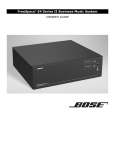
FreeSpace® E4 Series II Business Music System OWNER’S GUIDE Contents 1.0 E4 Introduction . . . . . . . . . . . . . . . . . . . . . . . . . . . . 1.1 The Bose® FreeSpace® E4 Series II business music system . . . . . . . . . . . . . . . . . . . . . . . . 1.2 E4 system accessories . . . . . . . . . . . . . . . . . . . 1.3 FreeSpace Installer™ software . . . . . . . . . . . . . 13 2.0 Designing with the E4 System . . . . . . . . . . . . . . . . . 2.1 Introduction . . . . . . . . . . . . . . . . . . . . . . . . . . . . 2.2 Basic design steps . . . . . . . . . . . . . . . . . . . . . . 2.2.1 Step 1 – Determine source routing . . . . . . 2.2.2 Step 2 – Determine Auto Volume requirements . . . . . . . . . . . . . . . . . . . . 2.2.3 Step 3 – Determine volume control requirements . . . . . . . . . . . . . . . . . . . . 2.2.4 Step 4 – Determine the speaker requirements . . . . . . . . . . . . . . . . . . . . 2.2.5 Step 5 – Determine the E4 requirements . 2.3 Auto Volume layout examples . . . . . . . . . . . . . . 15 15 15 15 3.0 E4 Hardware Description . . . . . . . . . . . . . . . . . . . . 3.1 Front panel . . . . . . . . . . . . . . . . . . . . . . . . . . . . 3.1.1 Controls . . . . . . . . . . . . . . . . . . . . . . . . . . 3.1.2 Indicators . . . . . . . . . . . . . . . . . . . . . . . . . 3.2 Rear panel . . . . . . . . . . . . . . . . . . . . . . . . . . . . . 3.2.1 System controls . . . . . . . . . . . . . . . . . . . . 3.2.2 Audio source inputs . . . . . . . . . . . . . . . . . 3.2.3 Amplifier outputs . . . . . . . . . . . . . . . . . . . 3.2.4 AC power . . . . . . . . . . . . . . . . . . . . . . . . . 23 23 23 23 24 24 24 24 24 4.0 Hardware Installation . . . . . . . . . . . . . . . . . . . . . . . . 4.1 Introduction . . . . . . . . . . . . . . . . . . . . . . . . . . . . 4.2 Included accessories . . . . . . . . . . . . . . . . . . . . 4.3 Placement guidelines . . . . . . . . . . . . . . . . . . . . 4.4 Shelf mounting the E4 unit . . . . . . . . . . . . . . . . 4.5 Rack mounting the E4 unit . . . . . . . . . . . . . . . . 4.6 Installing accessories . . . . . . . . . . . . . . . . . . . . 4.6.1 Sensing microphones . . . . . . . . . . . . . . . . 4.6.2 User interfaces . . . . . . . . . . . . . . . . . . . . . 4.7 System wiring . . . . . . . . . . . . . . . . . . . . . . . . . . 4.7.1 Auto volume microphone inputs . . . . . . . 4.7.2 Serial data communications . . . . . . . . . . . 4.7.3 User interface connections . . . . . . . . . . . . 4.7.4 Remote standby switch . . . . . . . . . . . . . . 4.7.5 LINE 1/LINE 2 source input . . . . . . . . . . . 4.7.6 AUX MIC/LINE 3 source input . . . . . . . . . 4.7.7 PAGE/MIC/LINE 4 source input . . . . . . . . 4.7.8 DIRECT IN/CONTROL source input . . . . . 4.7.9 Amplifier ZONE OUT outputs . . . . . . . . . . 4.7.10 Output voltage setting (70/100V) . . . . . . 4.7.11 ZONE 4 LINE OUT output . . . . . . . . . . . 4.8 AC power connections . . . . . . . . . . . . . . . . . . . 25 25 25 25 25 26 27 27 27 29 29 29 29 29 30 30 31 31 32 32 33 33 13 13 14 15 18 18 19 20 5.0 Using FreeSpace® Installer™ Software . . . . . . . . . . 5.1 Installing the software . . . . . . . . . . . . . . . . . . . . 5.2 Connecting to the E4 system . . . . . . . . . . . . . . 5.2.1 No hardware detected . . . . . . . . . . . . . . . 5.2.2 Incompatible microcontroller code . . . . . 5.2.3 Sample design files . . . . . . . . . . . . . . . . . 5.3 The Installer™ software user interface . . . . . . . 5.4 Set Up Hardware mode . . . . . . . . . . . . . . . . . . 5.5 Set Up Schedule mode . . . . . . . . . . . . . . . . . . . 5.5.1 Setting the clock . . . . . . . . . . . . . . . . . . . 5.5.2 Adding events . . . . . . . . . . . . . . . . . . . . . 5.5.3 Viewing and changing event settings . . . 5.5.4 Removing events from the list . . . . . . . . . 5.6 Service Hardware mode . . . . . . . . . . . . . . . . . . 34 34 34 36 36 36 37 39 40 41 41 42 42 43 6.0 E4 System Setup . . . . . . . . . . . . . . . . . . . . . . . . . . 6.1 Introduction . . . . . . . . . . . . . . . . . . . . . . . . . . . . 6.2 Connecting your PC to an E4 system . . . . . . . . 6.3 System setup procedure . . . . . . . . . . . . . . . . . 6.3.1 Output gain . . . . . . . . . . . . . . . . . . . . . . . 6.3.2 Zone setup . . . . . . . . . . . . . . . . . . . . . . . . 6.3.3 Input gain . . . . . . . . . . . . . . . . . . . . . . . . . 6.3.4 Source assign . . . . . . . . . . . . . . . . . . . . . 6.3.5 Source EQ . . . . . . . . . . . . . . . . . . . . . . . . 6.3.6 Page set up . . . . . . . . . . . . . . . . . . . . . . . 6.3.7 Zone EQ . . . . . . . . . . . . . . . . . . . . . . . . . . 6.3.8 Dynamic EQ . . . . . . . . . . . . . . . . . . . . . . . 6.3.9 Auto Volume . . . . . . . . . . . . . . . . . . . . . . . 44 44 44 45 45 46 47 49 50 50 52 53 53 7.0 User Interface Operation . . . . . . . . . . . . . . . . . . . . . 7.1 Enabling keypad operation . . . . . . . . . . . . . . . . 7.2 Turning the system on . . . . . . . . . . . . . . . . . . . 7.3 Standard user interface operation . . . . . . . . . . 7.4 Auto Volume user interface operation . . . . . . . 7.5 Multi-zone paging user interface operation . . . 59 59 59 59 60 61 8.0 E4 System Troubleshooting . . . . . . . . . . . . . . . . . . 8.1 Introduction . . . . . . . . . . . . . . . . . . . . . . . . . . . . 8.2 E4 hardware indicators . . . . . . . . . . . . . . . . . . . 8.2.1 Normal operation . . . . . . . . . . . . . . . . . . . 8.2.2 System fault . . . . . . . . . . . . . . . . . . . . . . . 8.2.3 Amplifier fault . . . . . . . . . . . . . . . . . . . . . . 8.2.4 Input clipping . . . . . . . . . . . . . . . . . . . . . . 8.2.5 Direct input is active . . . . . . . . . . . . . . . . 8.2.6 No STANDBY and SYSTEM indicators . . 8.3 FreeSpace® E4 system Error Log . . . . . . . . . . . 8.3.1 Contents of the Error Log . . . . . . . . . . . . 8.3.2 Hardware configuration . . . . . . . . . . . . . . 8.3.3 Power-on self-test results . . . . . . . . . . . . 8.3.4 Amplifier alarms . . . . . . . . . . . . . . . . . . . . 8.3.5 Solving faults reported in the Error Log . . 62 62 62 62 62 63 64 64 64 65 65 65 65 66 67 11 of 80 Contents 8.4 Common problems . . . . . . . . . . . . . . . . . . . . . . 8.4.1 Communications port error . . . . . . . . . . . 8.4.2 No audio in zone . . . . . . . . . . . . . . . . . . . . 8.4.3 User interface keypads do not operate correctly . . . . . . . . . . . . . . . . . 8.4.4 Bad sound in a zone . . . . . . . . . . . . . . . . . 8.4.5 Auto Volume does not calibrate . . . . . . . . 8.5 Customer support . . . . . . . . . . . . . . . . . . . . . . . 8.5.1 Technical assistance . . . . . . . . . . . . . . . . 8.5.2 Reporting software bugs and issues . . . . 68 68 68 69 69 70 70 70 70 9.0 Restoring E4 Microcontroller Code . . . . . . . . . . . . . 72 10.0 Technical Specifications . . . . . . . . . . . . . . . . . . . . 10.1 Power amplifier . . . . . . . . . . . . . . . . . . . . . . . . 10.2 Digital signal processing . . . . . . . . . . . . . . . . . 10.3 Front panel indicators and control connections . . . . . . . . . . . . . . . . . . . . . . . . . . 10.4 Rear panel inputs, outputs, and controls . . . . 10.5 E4 system serial data commands . . . . . . . . . . 10.6 FreeSpace® Installer™ Design File Compatibility . . . . . . . . . . . . . . . . . . . . . . . . . 74 74 74 74 74 74 76 12 of 80 5.0 Using FreeSpace® Installer™ Software 5.1 Installing the software 2. Insert the FreeSpace® Installer™ software CD into the CD tray of your laptop PC. Verify that the STANDBY indicator is lit on the E4 front panel. Then press the STANDBY push button to switch the E4 hardware to the operating mode. Set the E4 rear panel POWER switch to ON. If the install program does not start automatically, open “My computer” from the desktop, double-click on the CD-ROM drive icon, and double-click on the “Setup.exe” icon. POWER switch Follow the instructions on the screen to complete the installation. Programmer’s Note: For the Installer™ software to operate properly, your PC must be connected to the E4 hardware. See the following section, “Connecting to the E4 system”. RISK OF ELECTRICA L SHOCK DO NOT OPEN 2 OFF E OUT OUTPU T VOLTAGE 5.2 Connecting to the E4 system 70V geprüfte Sicherheit Bose Corporation, Framingham, MA 01701-9168 Made in the U.S.A. STANDBY push button STANDBY indicator AMPOUTPUTS 1 2 3 4 SYSTEM STATUS STANDBY RS-232 serial data cable (not provided) Laptop PC AUDIO SOURCES 1 E4 system SENSE MICROPHONES ZONE 1 ZONE 2 O Z NE 3 RS232 ZONE 4 WALLPLATE CONNECTIONS 2 REMOT E ON/OF F MUSIC ON HOLD/ PBX OUT ZONE4 LINE OUT 4 12V LINE 2 2 3 4 DIRECT INPUT USB RS232 LINE 1 100/120V~AC T6.25A, L250V 220/240V~AC T3.15A, L250V 50/60Hz 300W MAX FreeSpace Model E4 Series II 400 Watt System Electronics les. Operationis cemay not cause accept any interference ndesiredoperation. Using a serial cable (not supplied), connect the RS-232 serial port of your laptop PC to the RS-232 serial port on the rear panel of the E4 hardware. 3 100V DO NOT SWITCH WHILE POWER IS ON 1. Connect your PC to the E4 hardware. 1 ON POWER 4 To create a design file in FreeSpace Installer™ software, your PC must have an active connection with the E4 system hardware. This means that your PC must first be physically connected to the hardware device with a serial cable and then that connection must be activated using the software. RISQUE DE CHOC ELECTRIQUE NE P AS OUVRI R RING E OUT AUDIO SOURCES AUX MIC/ PAGE/ MIC/ LINE 3 LINE 4 PTT DIRECT IN / CONTROL PTT 34 of 80 5.0 Using FreeSpace® Installer™ Software 3. Programmer’s Note: If you encounter the “Choose COM port” dialog box, immediately follow the displayed recommendations for correcting the problem. DO NOT click the Cancel button until after trying each of the given recommendations. Launch the FreeSpace® Installer™ software. The Installer software splash screen will appear on your screen. Programmer’s Note: Before dismissing the “Choose COM port” dialog, select the COM 2 port and click Try Again. Not doing this will cause the COM 1 port to be locked. After the splash screen, a status dialog will appear and report the status of each installation stage. After your PC successfully connects to the E4 hardware, the Choose COM port dialog should automatically close. If not, close the window manually. 5. If you have connected to a new E4 system, use the E4 front panel window to set up the hardware. Refer to the “E4 System Setup” on page 44. Programmer’s Note: Clicking the Close button on the hardware connection status dialog will cause a communications failure, locking the serial port. At this point in the installation, the software looks for a connected E4 system, and if found, then checks to see what version firmware is running in the E4 system. If you get a “No hardware detected” dialog, see “No hardware detected” on page 36. If you get an Incompatible Microcontroller code dialog, see “Incompatible microcontroller code” on page 36. 4. If prompted, select the correct COM port for the E4 hardware. By default, the Installer software tries to locate a hardware device on the COM 1 serial port. If the E4 hardware is not detected on COM 1, the software displays a “Choose COM port” dialog box asking you to select the correct serial port. 35 of 80 5.0 Using FreeSpace® Installer™ Software 5.2.1 No hardware detected If after launching the Installer™ software a hardware device is not found, the status window reports a failure to detect connected hardware: In this case, clicking the Close button results in a blank hardware setup window. • Click Upgrade to upload the latest version of microcontroller code to the device. When the "Upload Complete" window appears, click Close. Then, finish the installation and configure your hardware device. Programmer’s Note: Upgrading new software does not change any of your current configuration settings. When the upgrade is finished, your current configuration will be restored. • Click Cancel to exit the software and leave the device untouched. In this case you will need to go to http:// pro.bose.com and download Installer™ software version 1.1. You will need to install this version on your PC to be able to configure your hardware device. 5.2.3 Sample design files Two sample design files are included with your FreeSpace® Installer™ software: • sample70V.fsi – for 70V E4 systems • sample100V.fsi – for 100V E4 systems Programmer’s Note: If you are not connected to the E4 hardware, you can see an example of the E4 front panel by opening the sample design file provided on the Installer CD. See “Sample design files” on page 36. They can be used to display an E4 front panel when your PC is not connected to a system hardware device. To open the sample design file: Programmer’s Note: To configure an E4 system, the E4 unit must be powered up. DO NOT switch the E4 unit to STANDBY mode while the Installer software is running. 1. Click the Open file tool in the Installer software window. 2. Select the name of the sample design file in your Installer software directory: C:\Program Files\FreeSpace Installer 2.0. Programmer’s Note: The Installer software does not notify you if there is a loss of communication between the E4 hardware and your PC. 3. Click the Open button in the dialog box. 4. Click on the “Bose FreeSpace E4” system name in the System Overview pane. The E4 front panel will appear in the application window. 5.2.2 Incompatible microcontroller code If the FreeSpace® Installer™ software finds that your system is running an older version of firmware (microcontroller code), the following window appears, giving you the opportunity to upgrade the code. 36 of 80 Programmer’s Note: If you are not connected to the E4 unit when you open a design file, all controls within the software are grayed out and not accessible. 5.0 Using FreeSpace® Installer™ Software 5.3 The Installer™ software user interface The following describes the software user interface. Tool box Mode buttons Window sizing tools Work area Control pane System overview pane 37 of 80 5.0 Using FreeSpace® Installer™ Software Tool box System overview pane – After connecting your PC to a system, this pane will list the hardware device. After you select the device to establish a connection, the name of the hardware device is highlighted. Open File – Displays the file open dialog. Save File – Saves the design file and the current settings of the connected hardware device to your PC’s hard drive. Name of system to which your PC is connected Currently-connected device Flash Hardware Configuration – Sends the design file and current settings from your PC to the memory of the connected hardware device. This determines the default startup state of the device. Detect Hardware – Uploads the design file and configuration settings from the system hardware to your PC. Help – Launches the online help system. Mode buttons Work area – The functions available for each mode are displayed in the work area. Set Up System – Selects the Set Up System mode enabling you to set up the system hardware or create a schedule to automate system operation. Hardware – Selects the Set Up Hardware mode. Schedule – Selects the Set Up Schedule mode. Control pane – The control pane is used to display the controls for the function selected in the work area. Service Hardware – Selects the Service Hardware mode. Window sizing tools Minimize Window – Collapses the application window into the Windows Task bar. Maximize Window – Function not available. Close Application – Closes the application program. 38 of 80 5.0 Using FreeSpace® Installer™ Software 5.4 Set Up Hardware mode Using the Set Up Hardware mode, you can create new system configurations. The following example displays the software front panel for the FreeSpace® E4 Series II system. The hardware setup window consists of three panes: System overview pane – This pane displays the selected hardware device that you are currently configuring. For more information on the system overview pane, see “The Installer™ software user interface” on page 37. Hardware pane – The hardware pane displays a software front panel of the hardware device that you selected in the system overview pane. Reading from left to right, this diagram shows you the functions and signal paths from input sources to output zones. All functions internal to the connected hardware device appear on a gray background. Functions are selected by clicking on a button. When you select a function, all controls for that function appear in the control pane. Control pane – When you select a function in the hardware pane, the controls that affect operation, configuration, or setup of the selected function or device appear in the control pane. On some control panes, you can view additional functions by clicking on More. Selected function Hardware pane Connected hardware System overview pane 39 of 80 Control pane for selected function 5.0 Using FreeSpace® Installer™ Software 5.5 Set Up Schedule mode The Set Up Schedule mode allows you to automate a system by creating up to 64 events. To select the Set Up Schedule mode, click the Schedule button under Set Up System. The features and controls of the Set Up Schedule window are as follows: Event list selection tabs – These tabs determine which list of events is displayed. Click the top tab to display the system event list. Click any one of the ZONE tabs to display the event list for a selected zone. Event list – This list contains all scheduled events for the selected system or zone. Each event entry includes the time of the event, a description of the event, and the days of the week on which the event will occur. Control pane – When you select an event in the event list, this pane displays the settings for that event. Any changes made to these settings are reflected in the event listing. Remove Event button – This button will remove a selected event from the event list. Hardware clock display – The clock display shows the current date and time of the hardware clock. The Set Clock button is used to set or change the clock. System overview pane – This pane displays the selected hardware device that you are automating. For more information on the system overview pane, see “The Installer™ software user interface” on page 37. Add event buttons – The Add Event buttons include On/Off, Mute, Volume, Source, and Auto Volume. The On/Off button is a system event only. Mute, Volume, Source, and Auto Volume are zone events. When you click one of these buttons, the event is added to the list and the controls for the selected event are displayed in the Event control panel. As events occur, the number of remaining events are displayed in parentheses above the On/Off button. Event list Event list selection tabs Add event buttons Hardware clock display System overview pane Control pane Event counter 40 of 80 Remove event button 5.0 Using FreeSpace® Installer™ Software 5.5.1 Setting the clock The date and time of the hardware clock is initially set in Eastern Standard Time. After your PC is connected to the hardware, check the clock and set it as necessary for the time zone and region of your installation. Adds a system Auto On/Off event This event applies only to the whole system. You can select individual on or off times for the day(s) you choose. Or, you can select on and off times in a single statement. Programmer’s Note: One Auto On/Off event specifies both an “On” time and an “Off” time and is counted as two events. To adjust the clock settings manually, click the Set Clock button in the clock panel. The Clock Settings window opens, allowing you to make adjustments to the date and time. Click Apply or OK to set the clock in the hardware, or click Cancel to close the window and leave the clock settings unchanged. Adds a zone Mute event This event allows you to mute/unmute the zone output at a specified time on selected days of the week. 5.5.2 Adding events When you click the On/Off, Volume, Source, or Auto Volume event button, an event of that type is added to the event list. At this point you can change the event settings. When the event list exceeds the length of the pane, the software will add a scroll bar on the right side. A maximum of 64 events may be added to a system. This means that the total number of events from all event lists must not exceed 64. An On-Off event consumes two events, while source change, volume change, and Auto Volume events consume one apiece. A counter is provided in the Schedule mode window to keep track of the number of remaining events. Adds a zone Volume Change event This event allows you to change the volume level at a specified time on selected days of the week. Remaining events counter Programmer’s Note: The maximum/minimum volume stops cannot be adjusted in this pane. To adjust these limit stops, select the Output Gain function in the Set Up Hardware mode. Zone events programmed to occur at the same time as a “System ON” event will not occur. To ensure that zone events will happen, they must be programmed to occur 15 minutes after the “System ON” event. For example, if a “System ON” event is programmed to occur at 8:00 AM, the first zone event should be programmed to occur at 8:15 AM. Installer’s Note: Flashing the Installer software configuration file to the E4 unit sets the default state of the system when it is turned on. Whenever possible the default state of the system should be set to meet the requirements most likely to occur after a scheduled “System ON” event. 41 of 80 5.0 Using FreeSpace® Installer™ Software 5.5.3 Viewing and changing event settings Adds a zone Source Change event This event allows you to change the source at a specified time on selected days of the week. To view any event and change the settings, first click the system or one of the zone tabs. Then select an event in the list to display the event settings in the control pane. Now, you can edit the settings just as when an event is added. 5.5.4 Removing events from the list To remove an event from the list, select the event by clicking on it and then click the (Remove Event) button. Programmer’s Note: After changing any event settings or removing an event from the list, you must flash the hardware in order for the change to take effect. Adds a zone Auto Volume event This event allows you to turn Auto Volume on or off at a specified time on selected days of the week. Programmer’s Note: Do not schedule an Auto Volume event on a zone that is not set up for Auto Volume. Programmer’s Note: Events are only saved to the E4 unit when you click the ration) button. (Flash Hardware Configu- 42 of 80 5.0 Using FreeSpace® Installer™ Software 5.6 Service Hardware mode Service Hardware button The Service Hardware mode provides a list of any system errors that have occurred. To view the Error Log, click the Service Hardware button. If you are already connected to hardware, the Error Log is retrieved from the hardware and displayed in the window. If not yet connected, select the hardware in the System Overview pane and after establishing the connection, click and then click (Detect Hardware) . When the FreeSpace E4 system is powered on, it performs a selftest. Any errors detected during a power-on cycle are appended to the Error Log. Likewise, any errors detected during normal operation are appended to the Error Log. The Error Log provides diagnostic information for repair technicians to help them repair the system. For more information on reported errors, see “FreeSpace® E4 system error log” on page 65. The buttons below the Error Log display allow you to manage the Error Log information: Uploads the current Error Log listing from the hardware. If you recently cleared the log, the Error Log will contain information reported only since the time you cleared it. Error Log Hardware version numbers Exports the Error Log to your hard drive as a text file. Clears the Error Log from the window and the E4 hardware. Type of alarm Name of test Test results 43 of 80 6.0 E4 System Setup 6.1 Introduction POWER switch Rear This section provides instructions on setting up an installed E4 system. To set up an E4 system you need a PC running the FreeSpace® Installer™ software. RISK OF ELECTRICA L SHOCK DO NOT OPEN RISQUE DE CHOC ELECTRIQUE NE P AS OUVRI R ON POWER OFF 6.2 Connecting your PC to an E4 system OUTPU T VOLTAGE 70V Before you can set up the E4 system, your PC must first be physically connected to the E4 unit with a serial cable and then that connection must be activated using the Installer™ software. 1. 100/120V~AC T6.25A, L250V 220/240V~AC T3.15A, L250V 50/60Hz 300W MA X DO NOT SWITCH WHILE POWER IS ON FreeSpace Model E4 Series II 400 Watt System Electronics ce Connect the RS-232 serial port of your PC to the RS-232 serial port on the rear panel of the E4 unit using a straight serial data cable. 100V Bose Corporation, Framingham, MA 01701-9168 Made in the U.S.A. SYSTEM STATUS indicator Green = Operating Red = Fault Front Laptop PC AMPOUTPUTS 1 RS-232 straight serial data cable (not provided) 2 3 4 SYSTEM STATUS RS232 STANDBY AUDIO SOURCES 1 2 3 4 DIRECT INPUT E4 system USB STANDBY indicator Amber = Standby Off = Operating SENSE MICROPHONES ZONE 1 ZONE 2 O Z NE 3 RS232 ZONE 4 STANDBY push button WALLPLATE CONNECTIONS 1 2 REMOT E ON/OF F 3 MUSIC ON HOLD/ PBX OUT ZONE4 LINE OUT CO OR 4 12V LINE 1 LINE 2 AUDIO SOURCES AUX MIC/ PAGE/ MIC/ LINE 3 LINE 4 DIRECT IN / CONTROL ® LISTED 917D AUDIO EQUIPMENT PTT 2. PTT Thisdevic subjectto harmful in received,i Complies 3. Set the E4 rear panel POWER switch to ON. When the E4 unit is powered up and ready, the SYSTEM STATUS indicator is dark (unlit) and the STANDBY indicator is amber. Press the STANDBY push button to switch the E4 hardware to the operating mode. The STANDBY indicator will turn off and the SYSTEM STATUS indicator will be green. (If a system fault condition exists, the indicator will be red.) Programmer’s Note: If the E4 system experiences a brownout or power loss, the E4 hardware will return to power in the STANDBY mode. To return to operation, press the STANDBY button, or press any key on any user Interface. 4. 44 of 80 Launch the Installer™ software. See “Using FreeSpace Installer Software on page 34 for the software launching sequence. 6.0 E4 System Setup 6.3 System setup procedure 6.3.1 Output gain The first time you turn on an E4 system it loads its factory (default) configuration settings. These settings were stored in the E4 when it was manufactured. Once your PC is fully connected to the E4 system, you can use the Installer™ software to make changes to the factory configuration settings. The controls in the Output Gain control panel allow you to control the amplifier output of the E4 system. Page gain setting Max. gain stop Gain Slider (Volume) Clipping indicator The configuration contains the “start-up” settings for the E4 hardware. Once your work is completed and flashed to the E4 hardware, the new settings become the startup configuration. 1. Select Output Gain for each zone and mute the output. This prevents any damage to speakers during this procedure. This also allows you to work without disturbing any other people in your work area. See “Output gain” on this page. 2. Set up the ZONE for each output channel. Choose a Speaker EQ (default is No EQ) for the speakers you are using. You can use the Subzones table to document your subzones. See “Zone setup” on page 46. 3. Set up the Input Gain controls for each source. Choose settings for input type, gain, and source leveling. If the input type is set for microphone use, you can turn phantom power (+12V) on or off. See “Input gain” on page 47. 4. Set up the Output Gain controls for each zone. Set the minimum/maximum gain (volume) limits and the initial gain level. See “Output gain” on this page. 5. Select Source Assign for each zone and assign sources for each. See “Source assign” on page 49. 6. Set up the source EQ for MIC/LINE 3 and MIC/PAGE/LINE 4 inputs. See “Source EQ” on page 50. 7. Select Page Set Up. See “Page setup” on page 50. 8. Select EQ for each zone. See “Zone EQ” on page 52. 9. Select the Dynamic EQ state for each zone. See “Dynamic EQ” on page 53. Page gain button Mute selection Min. gain stop Signal level meter Factory default settings Gain Max. Gain Min. Gain –20 dB 0 dB –60 dB Page Gain –20 dB Mute Off Output gain circuit block diagram Gain adjustment Signal level meter Clipping detector 10. Set up Auto Volume. See “Auto Volume” on page 53. 11. Create a System Schedule. See the “Set Up Schedule mode” on page 40. 12. Click the flash configuration button in the upper toolbox. You will be asked to confirm that you want to save the configuration to the E4 hardware. Once you confirm, the configuration and scheduling settings are sent to the E4 hardware. A copy of the Installer™ software design file is also sent to the hardware. Output gain setup sequence 1. Set the maximum output gain. This sets the maximum allowed volume within a zone. Play a source that will be used in that zone and raise the volume slider to the zero level. If it is too loud, lower the maximum gain stop. Programmer’s Note: If the source still plays too loud at the –30 dB setting, you should lower the tap setting on your speakers for optimal system performance. 45 of 80 6.0 E4 System Setup 2. Set the minimum output gain. This sets the desired minimum volume within a zone. Play a source that will be used in the zone and adjust the volume slider to the desired minimum level. Raise the minimum gain stop up to the volume slider level. 3. Set the initial output gain. When the E4 system is switched from standby to operating mode, it loads its configuration (initial settings). Wherever the volume slider is set when you save the configuration becomes the initial gain setting. Page Gain Setup The Page Gain function allows you to independently define a page level for each of the four output zones of the FreeSpace® E4 system. 1. Select the Out Gain function for the zone with paging. 2. Using the output gain slider, set the gain to the paging level you want for the output zone. 3. Click the Set button. The new Page Gain level is displayed above the Set button. Programmer’s Note: In an Auto Volume zone, the maximum and minimum level stops are disabled once an Auto Volume calibration is run. Mute selection – When checked, the Mute selection quiets the output audio. Signal level meter – The signal level meter displays the output level of the E4 system. Clipping indicator – The clipping indicator tells you when clipping is occurring in the amplifier. When indicated, clipping is caused by a low/reduced AC line voltage. 6.3.2 Zone setup The Zone Setup control panel allows you to select the EQ for the speakers used in a zone and to document (optional) the number of speakers in a subzone and their tap settings. Speaker model drop list Add subzone Delete subzone Programmer’s Note: When working with the Page Gain function, please note the following behaviors: • Moving the maximum gain stop to a point below the current Page Gain setting will set the Page Gain to the level of the new maximum output gain. • Moving the minimum gain stop to a point above the current Page Gain setting will set the Page Gain to the level of the new minimum output gain. Subzone table • If Auto Volume was calibrated for a zone with paging, you will be able to adjust the Output Gain and set the Page Gain when Auto Volume is off. Output gain controls Page Gain – Displays the Page Gain setting for the output zone. Speaker EQ – The Speaker EQ drop-down list contains a list of speakers by model name. The selected loudspeaker equalization settings are sent to the E4 hardware. Page Gain Set Button – Sets the Page Gain to the level defined by the gain slider position. Gain slider – This slide control adjusts the output gain. As you click and drag the slider, you will hear the level change. Release the mouse when you hear the level you want. The output gain is adjusted in an installed system by the Volume up/down buttons on the Standard or Auto Volume user interface. Programmer’s Note: In zones using Auto Volume, the volume may only be adjusted using the Auto Volume interface. Maximum and minimum gain stops – The maximum and minimum gain stops determine the maximum and minimum volume levels. Click and drag each stop to the values you want. If the stop meets the volume slider, the volume slider will move with the stop until the new setting is reached. When a Standard or Auto Volume user interface is used in a zone, the volume control cannot set the gain outside these limits. Mount code Each item in the list indicates a type of mounting: (F) for flush, (S) for surface, and (P) for pendant. Some items are listed more than once because they may be mounted in more than one way. For example, the Model 16 has two entries: one with an (F) for flush, and one with a (P) for pendant. The list also includes commonly used groupings, such as combinations of FreeSpace® 3 bass and mid/high devices. Use these settings when you are using the FreeSpace 3 bass on the same speaker line with other speakers. 46 of 80 6.0 E4 System Setup Programmer’s Note: If you are using the E4 system to drive speakers that are not Bose® products, choose the No EQ setting or one of the four high-pass filter settings at the end of the list. The No EQ setting helps protect the E4 against loudspeaker transformer saturation when non-Bose loudspeakers are connected to the E4 hardware. This setting acts as a band pass filter and allows energy between 80 Hz and 16 kHz to be sent to the amplifier section of the E4 electronics. 6.3.3 Input gain The Input Gain controls allow you to adjust functions related to the input source signal. Gain slider Source type Input signal level meter ® If you change the speaker EQ type, any subzones will be automatically changed to the new Speaker EQ setting, and be given the default loudspeaker tap. Depending on the quantity and tap of speakers, you could receive an error message notifying you that the system exceeds the 400 W limitation of the E4 system. If this problem occurs, delete the subzones from the subzone list. This will allow you to change the speaker EQ type. Subzones table – The Subzones table allows you to document the speakers used in a zone. A zone is a group of speakers that are driven by the same amplifier output channel. A subzone is a group of speakers within a zone that use a common tap or are of a common type. For example, you may have installed ten Model 16 speakers in a dining room and set it up as a zone to be driven by channel 1. In this zone you may have established two subzones, one with five Model 16 speakers tapped at 8W and the other with five tapped at 16W. Mic phantom power On/Off Opti-source input leveling On/Off Factory default settings Input Type Initial Gain Mic 40 dB 80 dB Off Line 0 dB 70 dB Off Mic Page 40 dB 80 dB On Line Page 0 dB 60 dB On Gain Range Opti-source Programmer’s Note: Input gain controls are disabled if the input channel is routed to a zone in which Auto Volume is enabled (on). You will only be able to change/ adjust the input gain by resetting the Auto Volume for the affected zone. To add a subzone Click the Add button. When the Add Subzone window appears, enter a name for the new subzone, select the speaker model installed, enter the quantity, and select a tap setting. The Model Name list will include only speakers that are compatible with the Speaker EQ you selected. Signal present indicator Input gain circuit block diagram Click OK to add the selections to the subzone table. Gain adjustment Signal level meter 3-band equalizer* EQ Opti-source leveling SRC LEVEL Signal detector * Only available for MIC/LINE and MIC/PAGE/LINE inputs. See “Source EQ” on page 50. To delete a subzone In the subzones table, select the subzone to be removed and click the Delete button. 47 of 80 6.0 E4 System Setup Input gain setup sequence Input gain meter – The input gain meter indicates the average input signal level of the hardware. The meter is divided into three color segments: 1. Set Opti-source® to Off. This allows you make the initial gain setting. 2. Select the source Type and determine if Mic Power +12V is needed. Set Mic Power to On if required. Leave it in the Off setting if you are using line inputs. Amber = Low signal level Start your input source and monitor its signal on the gain signal level meter. If the level is green, go to step 4. If the level is yellow, increase the input gain until the level is green. Likewise, if the level is red, reduce the input gain until the level is green. Red = High signal level 3. Green = Good signal level Signal present indicator – The signal present indicator tells you if a signal is being received by the hardware: Inactive = No signal Green = Good signal Programmer’s Note: You may have to repeat step 3 a few times if the input source is a CD player. The output level of a CD player varies based on the program material. 4. Set Opti-source to On. If you are using a source that produces a varying output level due to program material, such as a CD player, Opti-source leveling will compensate for these variances. If your system will be switching among multiple sources, Opti-source leveling will compensate for variances among the different sources. 5. Repeat steps 1 to 4 for the remaining system inputs. Red = Signal clipping Opti-source – This is the on/off control for this function. When on, Opti-source leveling automatically manages the input gain level so that the full output of the amplifier can be achieved. It does this by adjusting the input signal level to obtain the desired amplifier input signal level (+11 dBV). When setting the initial input gain level, check to make sure that Opti-source is Off. If you do not see this setting in the control pane, click on More to display the Opti-source On/Off boxes. Programmer’s Note: The Opti-source state cannot be changed when the Opti-voice® paging system is on. When you turn Opti-source on, you should only hear a small change in volume. If you hear a large increase, raise the input gain. Likewise, if you hear a large decrease, lower the input gain. Input gain controls Type – This setting determines the initial gain and amount of gain available for the input signal. The following table lists the choices for each input line. Input Line Input Type(s) Selection Initial Gain LINE 1 Line 0 LINE 2 Line 0 AUX MIC/ LINE 3 Line (default) Mic 0 40 PAGE/MIC/ LINE 4 Line Mic Line Page Mic Page (default) 0 40 0 40 The following chart shows how Opti-source leveling operates. For sources whose average input signal level is less than –20 dBV, Opti-source leveling will add 20 dB of gain. For sources whose average signal level is between –20 and 0 dBV, Optisource leveling will add the necessary gain so that the average output of the Opti-source function is +11 dBV. Sources whose average level is greater than 0 dBV will have gain reduction applied so that they maintain an average of +11 dBV at the Optisource leveling output. 25 17 9 Gain (dB) -1 Mic power +12V – This setting enables/disables +12V phantom power only for inputs 3 and 4, which are capable of accepting microphone signals. This power source is used for condenser type microphones. Gain slider – Click and drag the gain slider up/down to set the input gain. Changes in the slider's position are continuously sent to the E4 hardware so you will hear the change in gain as it is applied and see the change in the signal level on the meter. The gain range is dependent on the Type setting: 80 dB for Mic; 70 dB for Line. Programmer’s Note: When setting up the system, adjust the input gain slider until the meter is green. Occasional flashes of red are acceptable. Compression (dB) -7 -15 -30 -25 -20 -18 -15 -13 -10 -8 -5 -3 0 3 5 8 10 13 15 18 Input Signal Level (dBV) Input signals from –20 to 0 dBV fall within the ideal operating range for the Opti-source leveling function. This is reflected in the color scale used for the input gain signal level meter. If your input signal level is within the green area of –20 to 0 dBV, Opti-source leveling will effectively manage the input source level. 48 of 80 6.0 E4 System Setup 6.3.4 Source assign When the source appears in the ZONE Sources list, it is assigned to the current zone. Once a source is assigned to a zone, that source is no longer available in the System Sources list and appears grayed out. In the Source Assign control, you can choose which system sources will be available in each zone. The Source Assign control panel lists all system sources on the left and zone sources on the right. Sources are assigned by moving them from the System Sources list to the ZONE Sources list. To unassign a source Factory default settings 1. Select the source in the ZONE Sources list. 2. Click the left arrow () button to move the highlighted selection to the System Sources list. To route a source to a zone LINE 1 input source is assigned and routed to all four zones. Double-click on the source in the ZONE Sources list. When the source is routed, a sounding-speaker icon appears next to the source. Programmer’s Notes: • Because the E4 hardware is a router, at least one source must always be assigned to a zone. • If you try to remove all sources from a zone, the last active source will always remain assigned to the zone. • This function is disabled for zones in which Auto Volume is enabled (On). If you turn Auto Volume off and change source assignments, you will need to recalibrate Auto Volume. • Any source assigned to ZONE 4 will also be sent to the AUX OUT/CONTROL output. To assign a source to a zone 1. 2. Select a source in the System Sources list. Programmer’s Note: The FreeSpace® Installer™ software automatically disables keys of unassigned sources when a Flash Hardware Configuration command is performed. Click the right arrow ( ) button to move the highlighted selection to the ZONE Sources list. 49 of 80 6.0 E4 System Setup To set up paging in a zone 6.3.6 Page setup In order to use paging in a zone, first you must assign the PAGE source to the zone. Then select the appropriate settings in the Page Setup (page 50) control pane. The Page Setup control panel is used to set up the MIC/PAGE/ LINE 4 input for paging. The page setup is available when “Mic/ Page” or “Line/Page” is selected for “Type” in the Input Gain control panel. Paging type Detection type Active page indicator Ducking parameters 6.3.5 Source EQ An input source EQ control panel is available for inputs 3 and 4. This three-band equalizer is used primarily to compensate for microphone response or for handling noise. Page Control Opti-voice® On/Off Page threshold slider Page hold time Fixed-zone paging default settings Paging Type Detection Opti-voice® Fixed-zone PTT On Page setup with Opti-voice on (default) Click and drag each slider to the level you want. The scale on the left side of the panel is expressed in dB. Factory default settings Low Mid Hi 0 dB 0 dB 0 dB Since the Opti-voice paging system implements predetermined settings for ducking depth and release time and source EQ, this is the most efficient setup method. After the Opti-voice paging system is turned on, the rest of the setup depends on the chosen detection method. 1. Set Opti-voice to On in the Page Setup control panel. 2. Select a detection method. If you select PTT, there is no further setup required. If you select Auto, continue. 3. Ask another person to talk into the paging microphone at the lowest volume that will normally be used. 4. Lower the Page Threshold slider to the level where the page active light is constantly on. 5. Check your page threshold setting to make sure that no environmental noise, such as a music source or background noise, triggers the page. Source EQ operation The center frequency and shape of each EQ band is fixed and can be adjusted by ±6 dB. • The low-frequency EQ (LF-EQ) is a low-pass shelf EQ with a corner frequency of 125 Hz and a roll-off of 6 dB per octave. • The mid-frequency EQ (MF-EQ) has a center frequency of 1.6 kHz and a Q of 1. • The high-frequency EQ (HF-EQ) is a high-pass shelf EQ with a corner frequency of 8 kHz and a roll-off of 6 dB per octave below this point. • Increase the page threshold level. • Lower the taps on the speakers near the page mic. • Change the page mic location. LF-EQ MF-EQ If you hear the music source continually ramping up and down, the environmental noise is triggering a page. If this occurs, try one of the following: ∑ HF-EQ 50 of 80 6.0 E4 System Setup Page setup with Opti-voice® off Setting up Multi-zone paging 1. Set Opti-voice to Off in the Page Setup control panel. This enables the Ducking Depth and Release Time controls. 1. Assign the PAGE source to all zones that will be paged. See “To set up paging in a zone” on page 50. 2. Set the Ducking Depth to the amount in dB that the music will be reduced to once a page is triggered. 3. Set the Release Time to the length of time (secs.) it will take for the music to return to its original level. The Release Time can determine the overall quality of a page. 2. Select Multi-zone in the Paging Type drop list. 3. Select the wall plate connection for the page control keypad in the Page Control drop list. • Auto – Automatically senses input signal level. Requires that the Page Threshold level be set. 4. Set the Page Gain for each page zone. See “Page Gain Setup” on page 46. • PTT – Detects contact closure from push-to-talk (PTT) microphones. This disables the Page Threshold slider control. 5. Click the Flash Hardware Configuration button. • If you pause frequently while paging or release the pushto-talk (PTT) button during a page, use a long Release Time. • If the Release Time is too short, the music will quickly return and the level will be reduced once the page continues. Page setup controls Paging Type – Identifies whether you are using fixed-zone or multi-zone paging. • Fixed-zone – Enables paging in all zones that have the PAGE source assigned to them. • Multi-zone – Enables paging in all zones that have the PAGE source assigned to them and allows the user to select each zone independently using a Multi-zone Paging user interface. See “Source assign” on page 49, “Setting up Multi-zone paging” on page 51, and “Multi-zone paging user interface operation” on page 61. Page control – Selects which page keypad is used for paging. Active only when Paging Type is set to Multi-zone. Detection type – Determines the page trigger method: Opti-voice selection – The Bose® proprietary Opti-voice paging system provides the appropriate sound level regardless of variations in speech projection. When on, this feature implements predetermined settings for Ducking Depth and Release Time, and source EQ. Programmer’s Note: When the Opti-voice paging system is on, the Ducking, Source Leveling, and Input EQ controls are unavailable. Only when the Opti-voice paging system is off can these values be changed individually. Page Threshold slider – The Page Threshold slider setting determines the signal level required to trigger a page when Auto Detection is used. Page Active indicator – The Page Active indicator will be green when a page is being sent. Ducking parameters – There are three settings for ducking: • Depth – Determines how much to reduce the level of program material when a page starts. • Release Time – Determines the amount of time to keep program material reduced after a page ends. • Hold Time – Determines the amount of time that the page remains active after the page signal has stopped. Page length and Hold Time determine the point at which the Release Time starts. See “Paging operation” on page 52. 51 of 80 6.0 E4 System Setup Paging operation 6.3.7 Zone EQ When a page signal is triggered, the music signal is ramped down according to the ducking time. The ducking time is preset at 20 ms for Auto detection and 0 ms for PTT triggering. The music level is reduced by the ducking depth which can be adjusted using the ducking depth control. Ducking depth is adjustable from 0 to –40 dB. Once a page is completed and the Hold Time has elapsed, the music volume is ramped up according to the ducking release time, which is adjustable from 0 to 5 seconds in 0.5-second increments. The Zone EQ control panel provides a three-band equalizer for adjusting the sound quality of the zone. Hold Time 0 to 5 secs Click and drag each slider to the level you want. The scale on the left side of the panel is expressed in dB. Music signal Factory default settings Ducking depth 0 to –40dB Low Mid Hi 0 dB 0 dB 0 dB ZONE EQ operation The center frequency and shape of each EQ band is fixed and can be adjusted by ±6 dB. Page signal Ducking Time: Fixed at 20 ms for Auto Detection, 0 ms for PTT Detection. LF-EQ Release Time 0 to 5 secs MF-EQ Programmer’s Note: The attack time for a page is approximately 1 millisecond for a PTT input and 20 milliseconds for a voice-activated input. ∑ HF-EQ • The low-frequency EQ (LF-EQ) is a low-pass shelf EQ with a corner frequency of 125 Hz and a roll-off of 6 dB per octave. • The mid-frequency EQ (MF-EQ) has a center frequency of 1.6 kHz and a Q of 1. • The high-frequency EQ (HF-EQ) is a high-pass shelf EQ with a corner frequency of 8 kHz and a roll-off of 6 dB per octave below this point. 52 of 80 6.0 E4 System Setup 6.3.8 Dynamic EQ • DO NOT USE AUTOTRANSFORMERS: DO NOT use an auto transformer on the speaker line to adjust the speaker volume. Dynamic EQ will not operate properly with this added component. The Dynamic EQ control panel provides an on/off control to enable/disable Dynamic Equalization in the current zone. Volume Adjustment E4 System ZONE OUT 1 Speaker WALL PLATE CONNECTION 1 Dynamic EQ should only be used in either of the following conditions: ZONE 1 Standard or Auto Volume user interface • The system contains extended bass or a FreeSpace® 3 speaker system. • A user interface is being used to control the volume and no autotransformers are being used on the speaker line. When autotransformers are used, the system cannot accurately monitor the output level of the system, and as a result, cannot provide the appropriate response for the current listening level. Factory default settings 6.3.9 Auto Volume The Auto Volume function controls the volume level in a zone in relation to its environmental noise. Using the Auto Volume control pane, you can configure and calibrate this function for each zone. Auto Volume On/Off states Dynamic EQ is set to Off. Auto Volume Tracking settings Dynamic EQ compensates for a perceived loss of bass response at low listening levels. Based on the current output level of the E4 system, additional bass and high frequency will be added. For Dynamic EQ to operate correctly, make sure the hardware is connected properly: • An Auto Volume or Standard wall plate must be connected to the WALL PLATE CONNECTION input connector. • The speaker(s) must be directly wired to the ZONE OUT connector. Auto Volume calibration reset button ZONE 1 Auto Volume calibration button E4 System ZONE OUT 1 Speaker Factory default settings WALL PLATE CONNECTION 1 Standard or Auto Volume user interface 53 of 80 Auto Volume Auto Volume Tracking Off Equal to background noise 6.0 E4 System Setup IMPORTANT: Before you calibrate Auto Volume Auto Volume setup procedure Programmer’s Note: While the Auto Volume calibration is running, • Make sure that the system hardware installation is complete and that all components (sense microphones, speakers, and Auto Volume user interfaces) are properly connected. Remember that speakers must be directly wired to the ZONE OUT connectors on the E4 rear panel. ZONE 1 Sense E4 System Mic ZONE OUT 1 • DO NOT use the paging microphone. • Wait for the Auto Volume calibration to finish before adjusting other system functions. • DO NOT disconnect the RS-232 cable from the E4 unit. Speaker WALL PLATE CONNECTION 1 Auto Volume user interface 1. Click 2. Click More to display the Auto Volume Tracking settings. 3. Select Auto Volume Tracking settings for the type of system used in this zone. See “Auto Volume Tracking settings” on page 58. 4. Click Set Up to start the Auto Volume Setup process. The initial Auto Volume Setup dialog appears in the window. • Make sure that you have selected the correct speaker model in the ZONE setup pane. • Make sure that the output gain is set so that the source can be heard without dropping out. • Check that sources have been assigned to zones. Programmer’s Note: If a source is routed to multiple zones, you need to perform Auto Volume calibration on that source only once. After calibration, the source is “locked” (no adjustments to the source will be allowed) until all zones using that source have been reset. • Check the EQ pane and make any final adjustments. • DO NOT USE AUTOTRANSFORMERS: Speakers must be directly wired to the ZONE OUT connector of the E4 hardware. DO NOT use an autotransformer on the speaker line to adjust the speaker volume. If you lower the volume using an autotransformer, the E4 system will raise the volume. Likewise, if you raise the volume using an autotransformer, the E4 system will lower the volume. Sense Mic E4 System ZONE OUT 1 WALL PLATE CONNECTION 1 Volume Adjustment ZONE 1 Speaker Auto Volume user interface 54 of 80 button for the zone you want to calibrate. 6.0 E4 System Setup 5. 6. Click Continue. Your Auto Volume Tracking settings are confirmed. If the tracking settings are not correct, click the Cancel button, change the settings, and start the setup process again. 7. Click Continue. All sources assigned to the zone are listed in the window. You are asked to confirm that a source is connected and operating. If the source list is wrong, click the Cancel button, use the Source Assign control panel to correct the problem and start the process again. 55 of 80 Click Continue to begin the source calibration setup steps. Wait for the setup steps to be completed. Programmer’s Note: If you attempt to calibrate a source that is already calibrated, the dialog box will tell you that source calibration is being skipped. When the setup steps are done, you are asked to make volume adjustments. The maximum output gain should always be greater than -20 dB for proper Auto Volume operation. If the maximum output is less than -20, the source calibration procedure might fail. If your system is too loud in this range, change the speaker taps to a lower setting. 6.0 E4 System Setup 8. Click Continue to begin the source calibration process. 9. The source calibration process takes about three minutes per source. For each source, the input gain is measured and optimized, and the source level is activated. When this is done, the software displays the following confirmation. 56 of 80 Click Continue to begin the Zone Microphone Calibration. This calibration is performed using a test signal at the maximum zone volume and takes about 5 minutes. 6.0 E4 System Setup Programmer’s Note: If this process fails, a dialog similar to the following will appear. Check the sensing microphone installation and make sure all sources are operating. Following a successful microphone calibration, the software automatically flashes the hardware to save the configuration. 10. At the end of a successful Auto Volume calibration, the software displays a list of controls that are disabled when Auto Volume is on. Click Finish to exit Auto Volume Setup. The Auto Volume function is now On. Resetting a calibrated Auto Volume zone To cancel the calibration in an Auto Volume zone, click the Reset button. The Reset button is available only after a zone is successfully calibrated. When you reset a calibrated Auto Volume zone, the keypad control programming is restored to that of a Standard Wall Plate the next time you perform a hardware flash. Programmer’s Note: Be sure you want to reset the zone before you click the Reset button. If you reset the zone, you will need to run the Auto Volume setup process again before you can use Auto Volume. Click to reset Auto Volume calibration 57 of 80 6.0 E4 System Setup When to repeat the Auto Volume calibration You will need to repeat the Auto Volume process if: Band pass filter ZONE source input • You reset a calibrated zone. • You physically replaced source hardware. • You moved a sensing microphone. • You changed a speaker tap. Auto Volume Algorithm • The source hardware has an output control and you changed its setting after you calibrated Auto Volume. • You have flashed an existing file into a new hardware device in a new installation. The calibration specific to the new installation needs to be performed. ZONE sense mic Gain ZONE output gain Band pass filter • You upgraded the E4 microcontroller code. Auto Volume controls Auto Volume On/Off states – These selections appear grayed if the Auto Volume function is not calibrated. After a successful calibration, these controls are accessible and you can turn Auto Volume on and off. • When the Auto Volume function is on, pressing Volume s or Volume t on the Auto Volume user interface will turn Auto Volume off. To turn Auto Volume on again, press the Auto Auto Volume Tracking settings – These settings determine the ratio between the background noise and the program material. Once calibrated, the Auto Volume function maintains this ratio. These settings can be changed with some restrictions after calibration. See “Changing Auto Volume Tracking after calibrating a zone” on page 58. Set “Program Set “noise For this type of system is …” to by …” to • When you turn Auto Volume off on the user interface, the user interface remembers the volume level setting at the time you turned Auto Volume off. The volume level returns to that level when Auto Volume is turned on again. Background system (music level is less than room noise level) Foreground system (music level equals room noise level) Performance system (music level is greater than room noise level) less than 1, 3, or 6 dB equal to NA more than 1 or 3 dB Volume key . • When Auto Volume is on in two adjacent rooms and they are acoustically coupled, the same source must be played in each room. If this is not the case, each zone with Auto Volume will sense the other source as noise and try to overcome that noise. The result would be a very loud system. Changing Auto Volume Tracking after calibrating a zone Set Up (Auto Volume calibration) button – Clicking this button starts the calibration process. Once calibration is complete, the following functions are disabled for the applicable zone: After a zone is calibrated for Auto Volume, the Auto Volume Tracking settings can be changed according to the following table. • Input Gain controls for all sources routed to the zone If Auto Volume Tracking is It can be changed to more than 3 more than 1 more than 1 more than 3 • Auto Volume Tracking equal to less than 1, less than 3, or less than 6 • Output Gain controls less than 1 equal to, less than 3 or less than 6 Auto Volume reset button – Clears the Auto Volume calibration within the selected zone and enables the functions that were previously disabled. This button is enabled only when the zone is in a calibrated state. See “Resetting a calibrated Auto Volume zone” on page 57. less than 3 equal to, less than 1 or less than 6 less than 6 equal to, less than 1 or less than 3 • Source Type for all sources routed to the zone • Source Assign Auto Volume operation The Auto Volume function monitors the zone source input relative to the zone sensing microphone input. Based on these two inputs, the Auto Volume function determines if the output gain for the zone must be raised or lowered to maintain the predetermined program-to-noise ratio. 58 of 80 7.0 User Interface Operation 7.1 Enabling keypad operation Standard User Interface Example User interface keys for assigned sources are enabled only after flashing the hardware. Keys for any unassigned sources are automatically disabled after flashing the hardware. 7.2 Turning the system on When the E4 hardware is in STANDBY, you can turn the system on by pressing any key on any keypad except keys for unassigned sources on the Standard and Auto Volume user interfaces, and the PAGE key on the Paging Zone user interface. WALL PLATE 1 WALL PLATE 2 WALL PLATE 3 WALL PLATE 4 ZONE OUT 1 ZONE OUT 2 ZONE OUT 3 ZONE OUT 4 ZONE 2 Speakers ZONE 3 Speakers ZONE 4 Speakers 7.3 Standard user interface operation The Standard user interface provides source selection, volume up/down, and Mute controls. Standard User Interface Select LINE 1 input source Volume up (2 dB steps) Select LINE 2 input source Volume down (2 dB steps) ZONE 1 Speakers Select MIC/ LINE 3 input source Mute • Press 1, 2, or 3 to select the audio source connected to the LINE 1, LINE 2, or LINE 3 input, respectively. A green LED indicates the active source. • Press (Volume up) or (Volume down) to increase or decrease the volume in 2 dB steps. Press and hold for continuous increase/decrease. The red LED lights when either button is pressed. • The maximum/minimum volume setting is determined by the min./max. level stop settings in the Output Gain control pane. • Press (mute) to silence the listening area. When muted, a yellow LED flashes. Press again to restore the volume. 59 of 80 7.0 User Interface Operation 7.4 Auto Volume user interface operation Auto Volume User Interface Example The Auto Volume user interface provides source selection, volume up/down, and Auto Volume on/off controls. Auto Volume User Interface Select LINE 1 input source Volume up (2 dB steps) Select LINE 2 input source Volume down (2 dB steps) Select LINE 3 input source Auto Volume on/off • Press 1, 2, or 3 to select the audio source connected to the LINE 1, LINE 2, or LINE 3 input, respectively. A green LED indicates the active source. • Press (Volume up) or (Volume down) to increase or decrease the volume in 2 dB steps. Press and hold for continuous increase/decrease. The red LED lights when either button is pressed. • The maximum/minimum volume setting is determined by the min./max. level stop settings in the Output Gain control pane. • Press (Auto Volume) to turn the Auto Volume function on or off. The yellow LED lights when Auto Volume is on. • When the Auto Volume function is on, pressing or (Volume down) turns Auto Volume off. Press (Volume up) to turn Auto Volume on again. • When you turn Auto Volume off using the wall plate, the system remembers the volume level setting at the time you turned it off. The volume level returns to that level when Auto Volume is turned on again. 60 of 80 WALL PLATE 1 WALL PLATE 2 WALL PLATE 3 WALL PLATE 4 ZONE OUT 1 ZONE OUT 2 ZONE OUT 3 ZONE OUT 4 ZONE 2 Speakers ZONE 3 Speakers ZONE 4 Speakers ZONE 1 Speakers 7.0 User Interface Operation 7.5 Multi-zone paging user interface operation Paging User Interface Example: • The PAGE source is assigned to ZONE OUT 1 and ZONE OUT 4. The Multi-zone paging user interface provides keys to select single paging zones, all paging zones and initiate a page. • In the Page Setup control pane for ZONE 1 and ZONE 4: Paging zones are not the same as output zones. After assigning the PAGE source to the output zones and choosing the appropriate settings in the Page Setup control pane, flashing the hardware maps the paging zone buttons accordingly. Paging Type = Multi-zone PAGE Control = Wall plate 3 • After flashing the hardware, the paging zone 1 button selects ZONE OUT 1 for paging, and the paging zone 2 button selects ZONE OUT 4 for paging. When mapped, the paging zone 1 button will select the lowest numbered output ZONE to which the PAGE source is assigned. The paging zone 2 button will select the next lowest numbered output ZONE to which the PAGE source is assigned, and so forth. Multi-Zone Paging User Interface Select paging zone #1 Select paging zone #2 Select paging zone #3 Select paging zone #4 Select all paging zones Initiate a page • Press 1, 2, 3 or 4 to select a paging zone. A green LED flashes to indicate that the zone is selected for paging. After ending a page the LED turns off. Mapped to select ZONE 1 Mapped to select ZONE 4 Auto Volume Keypad Auto Volume Keypad Paging Keypad Standard Keypad WALL PLATE 1 WALL PLATE 2 WALL PLATE 3 WALL PLATE 4 ZONE OUT 1 ZONE OUT 2 ZONE OUT 3 ZONE OUT 4 ZONE 2 Speakers ZONE 3 Speakers ZONE 4 Speakers • Press ALL to select all paging zones. • Press PAGE to initiate a page in systems that do not use a PTT microphone. ZONE 1 Speakers Paging zone 1 61 of 80 Paging zone 2 Other Rights: Bose® Product Sales Conditions EXCLUSIVE REMEDY: Limited Warranty Policy and Conditions of Sale Bose Corporation The Mountain Framingham, MA 01701 What is covered: All parts defective in material and workmanship. This limited warranty for the Bose Freespace® E4 system (“system”) covers the functionality of the system for its normal, intended use as specified in the Owner’s Guide and does not cover a malfunction that has resulted from improper or unreasonable use or maintenance, accident, excess moisture, improper packing, lightning, power surges, or unauthorized tampering, alteration or modification while not under the control of Bose. Bose systems are not designed to be used in every environment, so please review your Owner’s Guide. WHERE PERMITTED, THE PROVISIONS OF THIS LIMITED WARRANTY ARE IN LIEU OF ANY OTHER WRITTEN WARRANTY, WHETHER EXPRESS OR IMPLIED, WRITTEN OR ORAL, INCLUDING ANY WARRANTY OF MERCHANTABILITY OR FITNESS FOR A PARTICULAR PURPOSE. For how long: In countries where the duration of the warranty is not determined by statute, the Bose Limited Warranty lasts five years from the purchase date. For countries where minimum warranty terms are determined by statute, the warranty term is the longer of the statutory period or the term listed above. What we will do: We will repair or replace any defective parts within a reasonable period of time and free of charge. How you can obtain warranty service: 1. You can ship the system to either a Bose Service Agency or to Bose directly with a proof of purchase from an authorized dealer. Please: A. Properly and carefully pack the product for shipping. If you need a carton for shipping, contact Bose for a new carton. B. Label and ship the product to the appropriate Bose location. C. Please contact Bose to get a return reference number. Place this number prominently on the outside of the carton. 2. You can return the system with proof of purchase from an authorized dealer to a Bose Service Agency or directly to Bose. Proof of purchase is not required where it is excluded by statute. THIS LIMITED WARRANTY IS FULLY TRANSFERABLE PROVIDED THAT THE CURRENT OWNER FURNISHES THE ORIGINAL PROOF OF PURCHASE FROM AN AUTHORIZED BOSE DEALER. THE MAXIMUM LIABILITY OF BOSE SHALL NOT EXCEED THE ACTUAL PURCHASE PRICE PAID BY YOU FOR THE PRODUCT. IN NO EVENT SHALL BOSE BE LIABLE FOR SPECIAL, INCIDENTAL, CONSEQUENTIAL OR INDIRECT DAMAGES. SOME PLACES DO NOT ALLOW LIMITATIONS ON THE EXCLUSION OR LIMITATION OF RELIEF, SPECIAL, INCIDENTAL, CONSEQUENTIAL OR INDIRECT DAMAGES OF THE LIMITATION OF LIABILITY TO SPECIFIED AMOUNTS, SO THE ABOVE LIMITATIONS OR EXCLUSIONS MAY NOT APPLY TO YOU. OTHER CONDITIONS: FOR YOUR BENEFIT, WE RECOMMEND THAT YOU RECORD YOUR SERIAL NUMBERS(S), FOUND ON THE PRODUCT(S), AND OTHER PURCHASE INFORMATION, AND KEEP IT WITH YOUR PERSONAL RECORDS ALONG WITH PROOF OF PURCHASE. IF NECESSARY, THIS INFORMATION WILL ALLOW US TO BETTER SERVE YOUR NEEDS. THIS LIMITED WARRANTY GIVES YOU SPECIFIC RIGHTS SUBJECT TO SPECIFIED CONDITIONS. YOU MAY ALSO HAVE OTHER LEGAL RIGHTS WHICH APPLY TO THE PRODUCT YOU HAVE ACQUIRED. THESE LEGAL RIGHTS VARY FROM STATE TO STATE OR COUNTRY TO COUNTRY. SOME PLACES DO NOT ALLOW THE EXCLUSION, RESTRICTION OR MODIFICATION OF CERTAIN IMPLIED RIGHTS OR THEIR EFFECT. IN THOSE SITUATIONS THIS LIMITED WARRANTY WILL ONLY APPLY TO THE EXTENT THAT THE APPLICABLE LAW ALLOWS. OTHER LAWS PROVIDE YOU WITH A STATUTORY CLAIM AGAINST THE SELLER. The laws of your state or country may provide you with legal claims against the seller or manufacturer of this product. The Limited Warranty does not affect those rights. Remedies: The provisions of this limited warranty are in lieu of any other warranties or conditions, except those provided by law. This Limited Warranty does not affect any legal rights provided to you by law and does not preclude any legal remedy you may have under the law. This Limited Warranty is fully transferable provided that the current owner furnishes the original proof of purchase from an authorized Bose dealer. This Limited Warranty is void if the label bearing the serial number has been removed or defaced. 77 of 78 78 ©2004 Bose Corporation, The Mountain, Framingham, MA 01701-9168 USA 279145 AM Rev.00 CCM-000922