1
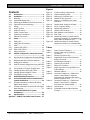
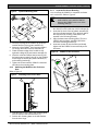
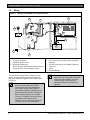
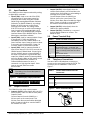
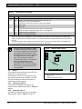
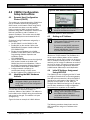
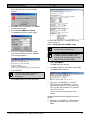
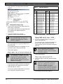
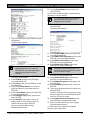
Conettix C900V2
Installation Guide
EN
Dialer Capture Ethernet
Module
Conettix C900V2 | Installation Guide | Trademarks
Trademarks
®
Altronix is a registered trademark of Altronix
Corporation.
Phillips® is a registered trademark of Phillips Screw
Company in the United States and other countries.
Windows® 98, Windows® 2000, and Windows® XP,
are registered trademarks of Microsoft Corporation in
the United States and/or other countries.
UL Listings and Approvals
The Conettix C900V2 Dialer Capture Ethernet Module
is UL Listed under the following standards:
• UL Central Station Burglary (1610), Encrypted
Line Security
• UL Commercial Fire Alarm Signaling (864),
Primary
• UL Police Station Burglar Alarm Units and
Systems (365)
• FCC Part 15 Radiated/Conducted Emissions
• cUL S304-M88, Central and Monitoring Station
Burglar Alarm Units
• C1076, Proprietary Burglar Alarm Units and
Systems
cUL installations approved for Level 3 Line Security
when communicating over a packet-switched data
network (PSDN). Install according to ULC-S302.
Refer to the D6200 Software Operation
and Installation Guide (P/N:
4998154991) for information on how to
prepare the D6600 or D6100i in your
Monitoring Center to receive UL Listed
communications from a Conettix
C900V2 Dialer Capture Ethernet
Module.
2
Bosch Security Systems, Inc. | 8/08 | F01U087780-01
Conettix C900V2 | Installation Guide | Contents
.
Contents
1.0
2.0
2.1
2.1.1
2.1.2
2.1.3
2.2
2.3
2.4
2.5
2.6
2.7
3.0
3.1
3.2
3.3
3.3.1
3.3.2
3.5
4.0
Introduction..................................................4
Installation....................................................4
Mounting ...................................................... 4
Optional Mounting Plate............................... 4
Attaching the Module to the Enclosure Door 5
Separate Enclosure Mounting...................... 5
Wiring........................................................... 6
Input Functions ............................................ 7
Output Functions.......................................... 7
Power Terminal Strip ................................... 7
Telephone Connections ............................... 7
Ethernet Connection .................................... 8
Setup.............................................................8
Setting P3 .................................................... 8
Setting the DIP Switches.............................. 8
LEDs .......................................................... 10
System LED (LED 1).................................. 10
Dialer LED (LED 2) .................................... 10
Dialer Interaction........................................ 12
C900V2 Configuration Setup Instructions
.................................................................... 13
4.1
Dynamic Host Configuration Protocol (DHCP)
................................................................... 13
4.2
Identifying the MAC Hardware Address ..... 13
4.3
Getting an IP Address ................................ 13
4.4
Initial IP Address Assignment Using ARP.EXE
................................................................... 13
4.5
Using Telnet to Finish the Configuration .... 14
4.5.1 Starting Windows 98SE, ME Telnet ........... 14
4.5.2 Starting Windows 2000/XP Telnet.............. 15
4.5.3 Configuration Using Telnet ........................ 16
5.0
Anti-Substitution Protection.................... 18
6.0
UL Standard 1610 and ULC S304 Intrusion
System Installations................................. 19
6.1
Protected Premises Control Panel without
Digital Dialer Backup.................................. 19
6.2
Protected Premises Control Panel with Digital
Dialer Backup............................................. 22
7.0
UL Standard 864 for Fire System
Installations............................................... 23
8.0
Specifications ........................................... 26
Appendix : C900V2 Compatible Data Formats ... 27
Bosch Security Systems, Inc. | 8/08 | F01U087780-01
Figures
Figure 1:
Figure 2:
Figure 3:
Figure 4:
Figure 5:
Figure 6:
Figure 7:
Figure 8:
Figure 9:
Figure 10:
Figure 11:
Figure 12:
Figure 13:
Location of Major Components .............. 4
Optional Mounting Plate ........................ 5
Attaching to Enclosure Door .................. 5
C900V2 in AE2 Enclosure ..................... 5
Wiring to a DS7400Xi in the Same
Enclosure............................................... 6
C900V2 Input, Output, and Power ......... 7
RJ-11 Connector Wiring ........................ 7
C900V2 DIP Switches ........................... 8
C900V2 LED Locations ....................... 10
MAC Address Label Example .............. 13
ARP Table ........................................... 14
C900V2 and Generic Control Panel in
Separate Enclosures (UL Standard 1610,
with or without Telephone Line) ........... 20
C900V2 and Generic Control Panel in
Separate Enclosures (UL Standard 864)
............................................................ 24
Tables
Table 1:
Table 2:
Table 3:
Table 4:
Table 5:
Table 6:
Table 7:
Table 8:
Table 9:
Table 10:
Table 11:
Table 12:
Table 13:
Power Terminal Functions ..................... 7
Control Panel and PSTN RJ-45
Connectors ............................................ 7
Ethernet Connector Pins........................ 8
Digital Dialer Protocol (DIP Switches 1
through 4, and 10) ................................. 9
DIP Switches 5 through 9 .................... 10
System LED Functions ........................ 11
Dialer LED Functions........................... 11
Dialer Interaction Forcing C900V2 into
Fallback Mode ..................................... 12
Netmask Address ................................ 16
Connection Sequence – C900V2 and
Generic Control Panel in Separate
Enclosures (UL Standard 1610, with or
without Telephone Line) ...................... 21
Connection Sequence – C900V2 and
Generic Control Panel in Separate
Enclosures (UL Standard 864)............. 25
Specifications ...................................... 26
Compatible Central Station Receiver
Formats ............................................... 27
3
Conettix C900V2 | Installation Guide | Contents
1.0 Introduction
2.1
Mounting
The C900V2 is static sensitive. Before
handling the circuit board, touch earth
ground to discharge any static electricity
from your body. Use a grounding strap
while installing the circuit board.
The Conettix C900V2 Dialer Capture Ethernet Module
(referred to as the C900V2) links the digital dialer
(data output) from a control panel to an Ethernet
connection on a local area network (LAN) or wide area
network (WAN).
When the dialer sends a message, the C900V2
simulates a public switched telephone network (PSTN)
connection to the central station. The C900V2
decodes the digital dialer message and sends the
decoded signals by Ethernet connection to the
Conettix D6600 or D6100i. Communication
Gateway/Receiver (referred to as the receiver). When
the receiver acknowledges receipt of the message, the
C900V2 sends an acknowledge message to the
dialer. This process maintains true end-to-end
security.
The C900V2 has three modular connectors:
• TELCO connects to the PSTN.
• PANEL connects to a digital dialer.
• Ethernet connects to the network.
In Intercept Mode, the C900V2 connects the digital
dialer to a LAN or WAN. In Fallback Mode, the
C900V2 connects the dialer to the PSTN, which
bypasses the C900V2 from the phone circuit. The
C900V2 stays in Intercept Mode when its CPU is
working (Output 1 open). In Fallback Mode, the
C900V2 connects the dialer directly to the PSTN. The
C900V2 switches to Fallback Mode if there is a CPU
or network failure.
2.0 Installation
Failure to follow these instructions can
result in the system failing to transmit an
alarm. Bosch Security Systems, Inc. is
not responsible for improperly installed,
tested, or maintained devices.
Notify the central station and the local
authority before installing the C900V2 in
an existing system.
Disconnect all power to the control
panel before installing the C900V2.
Figure 1:
Location of Major Components
3
L
2
H
4
1
8
5
7
6
1 – RJ-45 phone jack (to PSTN)
2 – RJ-45 phone jack (to control panel)
3 – High and low voltage selector (refer to
Section 3.1 on page 8)
4 – DIP switch (refer to Section 3.2 on page 8)
5 – RJ-45 Ethernet jack (to LAN or WAN)
6 – Power terminal strip (refer to Section 2.5 on
page 7)
7 – Input and output wiring terminals (refer to
Sections 2.3 and 2.4 on page 7)
8 – Dialer and system LEDs (refer to Section 3.3 on
page 10)
2.1.1
Optional Mounting Plate
Use an optional mounting plate (P/N: 40182) for
mounting the C900V2 on the door of a control panel
(D8103) or a fire control panel enclosure (D8109). You
cannot use the D8108A Attack Resistant Enclosure.
Mounting a C900V2 in a control panel
enclosure is approved by UL only when
used with a DS7400Xi as shown in
Figure 5 on page 6.
For the following procedure, refer to Figure 2 on page
5.
1. Insert the top hook of the supplied top (1) and
bottom plastic standoffs (2) into the mounting
plate brackets (3). Refer to Detail A.
2. Align the holes in the mounting brackets (3) and
the plastic standoffs (1 and 2).
4
Bosch Security Systems, Inc. | 8/08 | F01U087780-01
Conettix C900V2 | Installation Guide | Contents
.
Figure 2:
2.1.3
Optional Mounting Plate
Separate Enclosure Mounting
You can mount the C900V2 in a separate enclosure
such as the AE2. Refer to Figure 4.
A
3
Mount the enclosure on a vertical
surface before you install the C900V2
because the C900V2 covers one of the
mounting holes (9).
1
3
6
2
4
5
6
3. Place the top edge of the C900V2 (4) under the
standoff bracket of the top two standoffs (1).
4. Insert two of the Phillips® head screws provided
(5) through the holes in the top standoffs (3).
5. Lower the bottom edge of the module to rest
against the ledge of the two bottom standoffs (2).
6. Insert the other two Phillips head screws (5) into
the bottom two mounting holes (6) on the C900V2
and through the bottom two plastic standoffs (2)
and mounting bracket (3).
7. Tighten the screws until the C900V2 is attached
securely to the mounting plate.
2.1.2 Attaching the Module to the Enclosure
Door
Refer to Figure 3.
Figure 3:
1. Place the top edge of the C900V2 (1) between the
two slots (2) on the inside top of the enclosure (3).
2. Insert the top hook of the top plastic standoffs (4)
into the mounting brackets (5) on the back wall of
the enclosure (6), showing a side view of the
standoff in the mounting bracket).
3. Align the bottom two mounting holes (7) on the
C900V2 with the plastic standoffs (4) and the
enclosure mounting brackets (5).
4. Insert two screws (8) into the holes and slowly
tighten until the C900V2 is secured firmly to the
enclosure.
Figure 4:
C900V2 in AE2 Enclosure
8
1
2
3
7
4
Attaching to Enclosure Door
9
1
2
6
5
1. Slide the tabs (1) at the top of the mounting plate
over the top lip of the enclosure door (2).
2. Position the mounting plate on the side farthest
from the door hinge.
Bosch Security Systems, Inc. | 8/08 | F01U087780-01
5
Conettix C900V2 | Installation Guide | Contents
2.2
Wiring
Figure 5:
Wiring to a DS7400Xi in the Same Enclosure
3
1
2
10
9
4
6
5
8
7
1–
2–
3–
4–
C900V2
To LAN or WAN port
DS7400Xi Control Panel
Non-power limited area
NOTE: All power limited wiring must be at least
6.4 mm (0.25 in.) from the battery wiring.
You can use the C900V2 with a variety of control
panels. The next sections provide information for
wiring the C900V2 to a generic control panel. Refer
to Figure 5.
The control panel’s phone line monitor
becomes inactive when the C900V2
intercepts the phone line between the
telco service and the control panel. If
phone line monitoring is required, use an
external phone line monitor, such as the
Bosch Security Systems, Inc. DS7481.
5 – Battery
6 – EOL resistor for the control panel, attached to
terminals
7 – DS7481 Single Phone Line Monitor (optional)
8 – Telco jack
9 – RJ31X
10 – House telephone
The DS7400Xi is the only control panel
approved by UL to be wired in the same
enclosure as the C900V2. You must
install any other control panel in a
separate enclosure to receive the UL
approval.
The loss of a network connection closes
the Output 2 relay contact on the
C900V2. You can connect this output to
a 24-hour zone on the control panel.
6
Bosch Security Systems, Inc. | 8/08 | F01U087780-01
Conettix C900V2 | Installation Guide |
.
2.3
Input Functions
The C900V2 has three inputs monitored by analogto-digital (A/D) converters:
• Input 1 (IN1): Used as an end-of-line (EOL)
supervised loop. If input status reports are
enabled by the receiver using the Conettix
D6200 Programming/Administration Software
(referred to as D6200 Software), any voltage
below 1.66 VDC is sent as a short-circuit
message to the D6600. Any voltage above
3.33 VDC is sent as an open-circuit message.
Input 1 must be EOL-terminated with a 10 k
resistor. Refer to the D6600/D6100i Computer
Interface Manual (P/N: 4998122703) for Event
Messages to automation software.
• Input 2 (IN2): Used for Intercept Inhibit. If Input
2 rises above 5.5 VDC, the C900V2 is
immediately forced into Fallback Mode for at
least 2 minutes. Input 2 must go low for at least
5 seconds to be considered low. If Input 2 is
not used, allow it to remain disconnected.
• Input 3 (IN3): Used for Intercept Override. If
Input 3 rises above 5.5 VDC for 5 seconds, the
C900V2 enters Fallback Mode. If Input 3 goes
low, the C900V2 returns to Intercept Mode. If
this input is connected to a ground start relay
output, the C900V2 remains in Intercept Mode,
except to allow the dialer to dial. Input 3 cannot
force Intercept Mode if the C900V2 is in
Fallback Mode because of an error, a
command, or a high signal at Input 2. If this
input is not used, allow it to remain
disconnected.
You cannot use Inputs 1, 2 and 3 for UL
Fire Listing. You can use the inputs for
other purposes.
Figure 6:
C900V2 Input, Output, and Power
0V OUT4 OUT3 OUT2 OUT1 IN3
2.4
IN2 0V IN1 – V +
•
Output 2 (OUT2): Active (open) when the
receiver works properly, and closed when the
receiver does not respond to or acknowledge a
message sent from the C900V2.
Connect Output 2 from the C900V2 to a
24-hour zone on the control panel. This
24-Hour Zone Alarm Report enables the digital
dialer, if used, to indicate or sound a failure if
the network communications path fails.
•
Output 3 (OUT3): Active (open) when the
C900V2 is in Intercept Mode.
Output 4 (OUT4): Controlled by a command
from the D6200 Software or receiver. The
default is open.
•
2.5
Power Terminal Strip
Table 1:
Terminal
V (+)
V (–)
2.6
Power Terminal Functions
Description
Connect regulated 12 to 24 VDC power to
this terminal and the – V terminal. This
power can be supplied by a separate power
supply or auxiliary power from the control
panel.
12 to 24 VDC return.
Connect to earth ground.
Telephone Connections
Use two of the RJ-45 telephone connectors to
connect to the control panel and to the PSTN. The
connector pins are identified in Table 2 and
Figure 7.
Table 2:
Pin
1
4
5
8
Control Panel and PSTN RJ-45
Connectors
Connection
T1
T
R
R1
Output Functions
The C900V2 has four relay contact outputs:
• Output 1 (OUT1): Active (open) when the CPU
works properly. If the CPU fails or loses power,
Output 1 closes.
Connect Output 1 from the C900V2 to a
24-hour zone on the control panel. This
24-Hour Zone Alarm report enables the digital
dialer, if used, to indicate or sound a failure if
the C900V2 CPU fails.
Bosch Security Systems, Inc. | 8/08 | F01U087780-01
Figure 7:
RJ-11 Connector Wiring
8
1
1
7
Conettix C900V2 | Installation Guide | 3.0
2.7
Setup
Ethernet Connection
One of the RJ-45 jacks connects the C900V2 to
the Ethernet Network (LAN or WAN).
The connector pins are listed in Table 3.
Table 3:
Pin
1
2
3
6
Ethernet Connector Pins
Connection
TX+
TX–
RX+
RX–
3.0 Setup
3.1
Setting P3
A shorting link on P3 selects the voltage and
current applied to the alarm panel’s telephone
circuit to simulate the signal from a PSTN
telephone exchange. For most alarm panels, set
the shorting link to the H position (short the middle
and right pins of P3). The L position results in
slightly lower power consumption for the C900V2
but some alarm panels might report a telephone
line failure when dialing the C900V2.
3.2
Setting the DIP Switches
A ten-position DIP switch programs the C900V2.
The programming depends on the application and
dialer format of the control panel connected to the
module.
Figure 8:
1
2
C900V2 DIP Switches
3
4
5
6
7
8
9
10
O
N
1
2
1 – Off
2 – On
Because the C900V2 emulates a phone
line and a digital receiver, you must
program the C900V2 to the format it
receives from the control panel.
DIP Switch positions 1 through 4 and 10 program
the dialer format into the C900V2. Table 4 on page
9 lists the format programming for these DIP
switches.
For UL approved applications, the
shorting link must be set to the H
position.
8
Bosch Security Systems, Inc. | 8/08 | F01U087780-01
Conettix C900V2 | Installation Guide | 3.0
Setup
.
Table 4:
Digital Dialer Protocol (DIP Switches 1 through 4, and 10)
DIP Switches
Dialer Format of Host Alarm Panel
10
1
2
3
4
ON
OFF OFF OFF OFF Radionics Modem IIe and Modem IIIa2
ON
OFF OFF OFF ON
Radionics Modem II
ON
OFF OFF ON
OFF DTMF*
ON
OFF OFF ON
ON
DTMF* (where dialer retransmits quickly)
ON
OFF ON
OFF OFF BFSK (2300Hz ACK Tone)
ON
OFF ON
OFF ON
BFSK (1400Hz ACK Tone)
ON
OFF ON
ON
OFF FBI Superfast DTMF (2300 Hz ACK Tone) †
ON
OFF ON
ON
ON
FBI Superfast DTMF (1400 Hz ACK Tone) †
ON
ON
OFF OFF OFF Pulse 3/1, 3/1 Checksum (2300 Hz ACK Tone)
ON
ON
OFF OFF ON
Pulse 3/1, 3/1 Checksum (1400 Hz ACK Tone)
ON
ON
OFF ON
OFF Pulse 4/2 (Long 2300 Hz ACK Tone)
ON
ON
OFF ON
ON
Pulse 4/2 (Long 1400 Hz ACK Tone)
ON
ON
ON
OFF OFF SIA Bell 103 (110/300 baud, 2016 Hz ACK Tone)
ON
ON
ON
OFF ON
Reserved
ON
ON
ON
ON
OFF ADT-SIA†
ON
ON
ON
ON
ON
Reserved
OFF OFF OFF OFF OFF Reserved
OFF OFF OFF OFF ON
Reserved
OFF OFF OFF ON
OFF Scancom 481, 581, 681 †, ‡
OFF OFF OFF ON
ON
Reserved
OFF OFF ON
OFF OFF Reserved
OFF OFF ON
OFF ON
Reserved
OFF OFF ON
ON
OFF Telim †
OFF OFF ON
ON
ON
Robofon †
OFF ON
OFF OFF OFF Reserved
OFF ON
OFF OFF ON
Reserved
OFF ON
OFF ON
OFF Reserved
OFF ON
OFF ON
ON
Reserved
OFF ON
ON
OFF OFF SIA Bell 103 (110/300 baud, 2083 Hz ACK Tone) †
OFF ON
ON
OFF ON
SIA V.21 (110/300 baud) †
OFF ON
ON
ON
OFF Seriee DTMF †
OFF ON
ON
ON
ON
Seriee FSK †
* DTMF includes Contact ID, High Speed and 4/2 Express
† These formats have not been approved for UL 1610.
‡ Requires firmware version 1.12 or higher.
Bosch Security Systems, Inc. | 8/08 | F01U087780-01
9
Conettix C900V2 | Installation Guide | 3.0
Table 5:
Setup
DIP Switches 5 through 9
Switch
5
6
73
8
9
1
2
3
4
State
Function
ON
Enable auto Fallback Mode after detecting an intercept error.1
OFF
Disable auto Fallback Mode after detecting an intercept error.
ON
Hang-ups do not cause Fallback Mode.
OFF
Third hang-up without receiver ACK causes Fallback Mode.2
ON
240 sec poll
OFF
75 sec poll
ON
C900 sends initial handshake to panel after 6 sec dialing break.
OFF
C900 sends initial handshake to panel after 1 sec dialing break.
ON
Enable Anti-Replay/Substitution.4
OFF
Disable Anti-Replay/Substitution.
If an error occurs in the Intercept Mode, the C900V2 automatically returns (falls back) to the telco line.
If the receiver does not acknowledge a report intercepted by the C900V2 in the specified time, the digital dialer
hangs up and retries the message transmission. The C900V2 switches to Fallback Mode based on the number of
hang-ups.
The time that elapses between polls from the C900V2 when it is idle (not expecting a dialer acknowledgement).
This DIP switch must be set to ON if the receiver is set up for NNC Mode.
Any error forces the C900V2 to switch
to Fallback Mode (phone line backup)
for 2 min the next time the control panel
seizes the line (if DIP Switch 5 is ON,
DIP Switch 6 is OFF, or both, and if the
control panel seizes the line within 2
min). Intercept errors are always
reported to the receiver. If the receiver
does not acknowledge a signal
intercepted by the C900V2 in the
specified time, the control panel digital
dialer hangs up and tries to send the
message again.
3.3
C900V2 LED Locations
L
H
1
2
LEDs
The C900V2 has two dual-color status LEDs: the
system LED and the dialer LED.
The Ethernet connector also includes two LEDs
that indicate the status of the network connection.
The right LED lights or flashes when there is a
valid connection to the network.
3.3.1
Figure 9:
3
1 – System LED
2 – Dialer LED
3 – Ethernet connector LEDs
System LED (LED 1)
The system LED indicates the status of the
receiver and the C900V2 itself. Refer to Table 6 on
page 11.
3.3.2
Dialer LED (LED 2)
The dialer LED indicates the status of the digital
dialer interface. Refer to Table 7 on page 11.
10
Bosch Security Systems, Inc. | 8/08 | F01U087780-01
Conettix C900V2 | Installation Guide | 3.0
Setup
.
Table 6:
Color
None
Green
System LED Functions
State
Off
Solid
Flashing (5 Hz)
Solid
Flashing (5 Hz)
Flashing
(Repeating
Code)
Alternating (5 Hz)
Red
Function
No power.
C900V2 failed.
The receiver is responding normally.
C900V2 failed.
The receiver is not responding.
1 flash: ROM checksum error
2 flashes: RAM test error
Red/
The dialer is off-hook, but the last message was rejected because of a bad checksum or
Green
other logical error.1
1
If the dialer subsequently sends a valid message, the LED returns to a blinking green status. If the dialer hangs up, an
intercept error is generated. The alternating LED also occurs when the line is seized, but no transaction occurs (for
example, the C900V2 is waiting for the dialer to return on-hook). This happens when the C900V2 returns to Intercept
Mode, or while the dialer seizes the line.
Table 7:
Color
None
Green
Dialer LED Functions
State
Off
Solid
Flashing (5 Hz)
Solid
Function
C900V2 is in permanent Fallback Mode due to a command or no power.
C900V2 is in Intercept Mode and the dialer is on-hook.
C900V2 is in Intercept Mode and the dialer is off-hook.
Red
C900V2 is in Fallback Mode due to an error, Intercept Inhibit or Override inputs, or a
command.
Flashing (5 Hz)
An off-hook condition caused an intercept error.1
Red/
Alternating (5 Hz) The dialer is off-hook, but the last message was rejected due to a bad checksum or other
Green
logical error.2
1
If Auto Fallback After Error is enabled (DIP Switch 5 = ON), the C900V2 connects the dialer to the phone line at the
next line seizure. If the dialer does not seize the line, this condition terminates after two min.
2
If the dialer subsequently sends a valid message, the LED returns to a blinking green status. If the dialer hangs up, an
intercept error is generated. The alternating LED also occurs when the line is seized, but no transaction occurs (for
example, the C900V2 is waiting for the dialer to return on-hook). This happens when the C900V2 returns to Intercept
Mode, or while the dialer seizes the line.
Bosch Security Systems, Inc. | 8/08 | F01U087780-01
11
Conettix C900V2 | Installation Guide | 3.0
3.4
Setup
3.5
Fallback Mode
In fallback operation, the C900V2 connects the
PSTN directly to the dialer, bypassing itself from
the phone circuit. Intercept Mode is maintained
only if the C900V2 processor operates and there
are no errors. Fallback Mode is ensured if a CPU
lockup occurs.
Table 8:
Table 8 shows the conditions causing the C900V2
to change to Fallback Mode. The C900V2 returns
to Intercept Mode only when all conditions in the
Intercept Mode Restored column are met.
Dialer Interaction Forcing C900V2 into Fallback Mode
Condition
CPU fails
Receiver fails
Receiver does not respond
to last message
Intercept Disable Command
Intercept Error
Switch to Fallback command
12
Dialer Interaction
Fallback Mode Occurs
Immediately
Immediately
Dialer goes off-hook (disconnected)
Intercept Mode Restored
C900V2 restart
Link restored
Link restored
On receipt of the command
If Fallback after intercept error is enabled, the
dialer goes off-hook within two minutes of the
error
On receipt
Intercept Enable command
After two minutes
One hour or at receipt of Intercept
Enable command
Bosch Security Systems, Inc. | 8/08 | F01U087780-01
Conettix C900V2 | Installation Guide | 4.0
C900V2 Configuration Setup Instructions
.
4.0 C900V2 Configuration
Setup Instructions
4.1
Dynamic Host Configuration
Protocol (DHCP)
The receiver can communicate with a C900V2 that
has an IP address dynamically assigned by a
DHCP server on the network. When using DHCP,
you must set the receiver to use the network
naming convention (NNC) to identify accounts
instead of using static IP addresses. Devices in the
field can have either a static IP address or a
dynamic IP address. The receiver uses the NNC
number to identify the account instead of the IP
address.
For devices having IP addresses assigned by a
DHCP server:
• Set DIP Switch 9 on the C900V2 to ON.
• Enable NNC on the receiver. Refer to the
D6600/D6100i Computer Interface Manual
(P/N: 4998122702).
• Set the Account Database in the D6200
Software to NNC Mode. Refer to the D6200
Programming Software Operation and
Installation Guide
(P/N: 4998154991).
• Use the D6200 Software to enter the eight-digit
NNC number located on the label of the
C900V2 into the Account Database.. Refer to
the D6200 Programming Software Operation
and Installation Guide (P/N: 4998154991).
• Configure network connections to
communicate through a DHCP server.
• Set the IP address of the C900V2 to 0.0.0.0.
4.2
Figure 10: MAC Address Label Example
Identifying the MAC Hardware
Address
If you know the IP address of the
configured C900V2, go to Section 4.5
Using Telnet to Finish the Configuration
on page 14.
You must program the IP address of the C900V2.
The first step is to determine the MAC, or
hardware, address of the C900V2. This address is
hard-coded into the C900V2 during its manufacture
and cannot be changed. This address is 6 bytes
(12 digits) long.
The MAC address label is located on
the top of the Ethernet connector.
Record this number for future reference.
4.3
Getting an IP Address
If you are using Dynamic Host
Configuration Protocol (DHCP), you do
not need an IP address.
If you are not using DHCP, request an
IP address for your C900V2 from your
network administrator. You might have
to provide the MAC address.
An IP address is an identifier for a computer or
device on a TCP/IP network. The IP address is a
32-bit numeric address written as four numbers
separated by periods. Each number can be zero to
255, for example, 190.200.128.111. In an isolated
network, you can assign IP addresses at random if
each one is unique. Connecting a private network
to the Internet requires registered IP addresses
(called Internet addresses) to avoid duplication.
4.4
Initial IP Address Assignment
Using ARP.EXE
The C900V2 you are configuring and the PC used
to configure it must both be on the same gateway
(the device that connects the LAN to the WAN) to
use telnet for configuration of the C900V2. The
gateway can be a router or a hub. After you
configure the C900V2 and assign it an IP address,
you can then use telnet to change configuration
parameters from anywhere on the network.
Read this entire procedure before
starting. Ensure that power is applied to
the C900V2 and the C900V2 is
connected to the LAN or WAN through
the Ethernet connector.
Figure 10 shows an example of a MAC address.
The following procedure shows how to use the
ARP command to assign an IP address to the
C900V2.
Bosch Security Systems, Inc. | 8/08 | F01U087780-01
13
Conettix C900V2 | Installation Guide | 4.0
C900V2 Configuration Setup Instructions
The IP and MAC addresses in this
procedure are examples and are not the
same as those for your C900V2.
Figure 11: ARP Table
1. Select Start Æ Run.
The Run dialog box appears.
2. In the Run dialog box, type COMMAND and
click OK.
A DOS window appears:
3. At the DOS command line, type:
arp -s xxx.xxx.xxx.xxx zz-zz-zz-zz-zz-zz
and press [ENTER].
•
•
xxx.xxx.xxx.xxx is the IP address the
network administrator assigned to the
C900V2
zz-zz-zz-zz-zz-zz is the MAC address
printed on the Ethernet connector label.
For example:
The network uses this table to identify devices and
to route signals. The number of devices and other
types (static and dynamic, as shown in the
example) depends on the network and the number
and type of devices with which this PC
communicates. Identify the MAC address of the
device you are installing and verify that it now has
an IP address linked to it.
4.5
Using Telnet to Finish the
Configuration
Use the telnet program to configure the C900V2.
The procedure for Windows 98SE, ME is different
from the procedure for Windows 2000 and
Windows XP.
4.5.1 Starting Windows 98SE, ME Telnet
1. Select Start Æ Run.
The Run dialog box appears.
2. In the Run dialog box, type telnet and press
[ENTER].
The Telnet application window appears.
The program responds with a prompt to
indicate that the address was accepted.
3. Select Connect Æ Remote System.
The program does not indicate that the
operation was performed properly. The
only indication is the absence of an
error message.
The Connect dialog box appears.
4. Verify that you entered the IP address
correctly. Type:
arp -g
and press [ENTER].
This command displays the IP address
172.17.10.70 temporarily linked to MAC address
00-20-4a-12-04-0e as shown in Figure 11. The
temporary link shows a static entry.
14
a. In the Host Name field, type the IP
address of the C900V2.
b. In the Port, field type 1.
c. Accept vt100 as the TermType field.
d. Click Connect.
Bosch Security Systems, Inc. | 8/08 | F01U087780-01
Conettix C900V2 | Installation Guide | 4.0
C900V2 Configuration Setup Instructions
.
After a few seconds, an error message
appears.
4. Click OK to clear the message. The Telnet
window appears again.
5. Select Connect Æ Remote System.
The Connect dialog box appears again.
Continue with Section 4.5.3 Configuration Using
Telnet on page 16.
4.5.2
Starting Windows 2000/XP Telnet
To do this procedure, you must log in at
an administrator privilege level.
6. This time, change the Port field to 9999,
accept the other fields, and click Connect.
This message appears.
The MAC address, IP address, gateway
IP address, and port number in this
procedure are examples and are not the
same as those for your C900V2.
1. Select Start Æ Run.
The Run dialog box appears.
2. In the Run dialog box, type telnet and click OK.
7. Press [ENTER].
The Telnet window appears.
You must press [ENTER] within five
seconds or the telnet session
disconnects.
The Telnet window shows this information.
3. Type open <IP ADDRESS> 1 and press
[ENTER] (where <IP ADDRESS> is the IP
address of the C900V2). Type a space after
open and after the IP address. For example:
open 172.17.10.70 1.
The connection fails the first time. This is
normal.
Repeat the previous step using 9999 as the port
number:
4. Type open <IP ADDRESS> 9999 and press
[ENTER] (for example, open 172.17.10.70
9999).
Bosch Security Systems, Inc. | 8/08 | F01U087780-01
15
Conettix C900V2 | Installation Guide | 4.0
C900V2 Configuration Setup Instructions
5. Press [ENTER]. The Setup Mode information
appears.
Continue with Section 4.5.3 Configuration Using
Telnet.
4.5.3 Configuration Using Telnet
1. Type 0 (zero) and press [ENTER] to set up the
basic server configuration.
If the C900V2 was previously programmed with
an IP address, the address appears in
parentheses.
2. Type the IP address (for example,
190.200.128.219) and press [ENTER].
If you are using DHCP type 0.0.0.0 and
press [ENTER]. Refer to Section 4.1
Dynamic Host Configuration Protocol
(DHCP) on page 13.
3. If the Gateway address is required, type y,
press [ENTER] and then type the address and
press [ENTER].
If the Gateway address is not required or if you
use DHCP, type n and press [ENTER]
This prompt appears.
The Gateway IP is required only if you
are connecting to a WAN. In a LAN, the
Gateway IP is usually not needed
unless the Gateway IP of the PC is
different from the Gateway to which the
C900V2 is connected.
4. If using DHCP, press [ENTER].
If not, enter the number of bits that correspond
to the netmask your network uses and press
[ENTER]. Refer to Table 9.
Contact your network administrator if you need
more information about the netmask.
16
Table 9:
Host
Bits
1
2
3
4
5
6
7
8
9
10
11
12
13
14
15
16
Netmask Address
Netmask
255.255.255.254
255.255.255.252
255.255.255.248
255.255.255.240
255.255.255.224
255.255.255.192
255.255.255.128
255.255.255.0
255.255.254.0
255.255.252.0
255.255.248.0
255.255.240.0
255.255.224.0
255.255.192.0
255.255.128.0
255.255.0.0
Host
Bits
17
18
18
20
21
22
23
24
25
26
27
28
29
30
31
Netmask
255.254.0.0
255.252.0.0
255.248.0.0
255.240.0.0
255.224.0.0
255.192.0.0
255.128.0.0
255.0.0.0
254.0.0.0
252.0.0.0
248.0.0.0
240.0.0.0
224.0.0.0
192.0.0.0
128.0.0.0
If you are using DHCP, this prompt appears.
5. If you do not want to assign or change the
name, press [ENTER].
If you want to assign a name for this device for
use on a LAN, type y and press [ENTER}.
Type the name, up to 16 characters, and press
[ENTER].
If you do not enter a DHCP device
name, a default name of Cxxxxxx is
used (where xxxxxx is the last six digits
of the MAC address).
This prompt appears.
6. Press [ENTER] to accept the password setting
at none.
In most cases, do not assign a
password. If a password is necessary,
store it in a safe place. If you lose or
forget the password, you cannot
connect to C900V2 using telnet until you
send the unit to the factory for password
removal, and the unit is returned to you.
The Setup Mode information appears.
Bosch Security Systems, Inc. | 8/08 | F01U087780-01
Conettix C900V2 | Installation Guide | 4.0
C900V2 Configuration Setup Instructions
.
15. Type the Port Number for the receiver and
press [ENTER].
If you want to enable encryption, continue with the
next step. If not, go to step 27.
If you enable encryption on the C900V2,
you must enable encryption on the
D6680 with the same key.
16. From the Change Setup menu, type 6 and
press [ENTER].
This information appears.
7. Type 1 and press [ENTER] to set up Channel 1
configuration.
This information appears.
8.
9.
10.
11.
12.
13.
14.
If the default value displayed in your
Telnet window does not match the
value listed in any of the steps below,
type the correct value and press
[ENTER].
At the Baud Rate prompt, press [ENTER] to
accept the default (9600).
At the I/F Mode prompt, press [ENTER] to
accept the default (4C).
At the Flow prompt, press [ENTER] to accept
the default (00).
Type a unique Port Number for the LAN to
which the C900V2 is connected and press
[ENTER].
At the ConnectMode prompt, press [ENTER]
to accept the default (CC).
At the Datagram Type prompt, type 01 and
press [ENTER].
At the IP addr prompt, type the remote IP
address used for the receiver to which the
C900V2 reports and press [ENTER].
Enter the remote IP address using
000.000.000.000 format.
Bosch Security Systems, Inc. | 8/08 | F01U087780-01
17. At the Disable SNMP prompt, press [ENTER]
to accept the default (N).
18. At the SNMP Community Name prompt, press
[ENTER] to accept the default (public).
19. At the Disable Telnet Setup prompt, press
[ENTER] to accept the default (N).
20. At the Disable Port 77FEh prompt, press
[ENTER] to accept the default (N).
21.
22.
23.
24.
25.
Disabling both the telnet and port 77FE
prevents you from accessing the set-up
menu for future changes.
At the Disable Web Server prompt, press
[ENTER] to accept the default (N).
At the Disable ECHO ports prompt, press
[ENTER] to accept the default (Y).
At the Enable Encryption prompt, type y and
press [ENTER].
At the Change keys prompt, type y and press
[ENTER].
Type the key programmed for the receiver and
press [ENTER].
The key is 16 bytes (32 characters) long. Enter
the key using the 01-02-03-04-05-06-07-08-0910-11-12-13-14-15-16 format.
26. At the Enable Enhanced Password prompt,
press [ENTER] to accept the default (N).
27. Type 9 and press [ENTER] to save changes
and exit the telnet session.
To confirm that the IP address is configured
properly, use the ping utility:
17
Conettix C900V2 | Installation Guide | 5.0
Anti-Substitution Protection
28. At the C:\> prompt, type ping <IP Address>
and press [ENTER].
Four reply messages are received, confirming
the C900V2 is communicating on the network.
Configuration of the C900V2 is complete.
18
5.0 Anti-Substitution
Protection
1. Remove power from the C900V2.
2. Set DIP Switch 9 to the ON position (the
factory default). Refer to Section 3.2 Setting
the DIP Switches on page 8.
3. Apply power to the C900V2.
After rebooting the C900V2, the unit exchanges
numeric keys with the receiver, and they become
synchronized. Once they are synchronized, all
subsequent communications sessions numerically
validate the authenticity of the sender and receiver.
Each session generates an entirely new set of
keys, which invalidates the replay of authentic
sessions.
Bosch Security Systems, Inc. | 8/08 | F01U087780-01
Conettix C900V2 | Installation Guide | 6.0
UL Standard 1610 and ULC S304 Intrusion System Installations
.
6.0 UL Standard 1610 and
ULC S304 Intrusion
System Installations
5. Connect Output 1 from the C900V2 to a
24-hour zone on the control panel.
To install the C900V2 to comply with UL Standard
1610 Applications (for Line Security, formerly
“Grade AA”) and ULC S304, you must satisfy all
requirements in this section.
6. Connect Output 2 from the C900V2 to a
24-hour zone on the control panel.
6.1
Protected Premises Control
Panel without Digital Dialer
Backup
1. Use the D6200 Software to set the poll rate on
the C900V2. For UL approved installations, the
maximum interval is 90 seconds to meet the
requirement for polling supervision established
by UL. In most cases, to get a polling
supervision interval of 90 seconds, set the Poll
Rate to 75 and Retry to 13.
Because of differences in packet transmission
time latency within different networks, the poll
rate times vary. Contact Technical Support at
Bosch Security Systems, Inc. for assistance in
establishing the latency time for the network on
which you are installing the C900V2.
Refer to D6200 Software Operation and
Installation Guide (P/N: 4998154991).
2. Set DIP Switch 7 to the OFF position to enable
75-second supervision signals (the factory
default).
Refer to Table 5 on page 10 for the
functions of DIP Switches 5 through 9.
3. Add a telnet password to the communications
protocol of the C900V2 (refer to Section 4.5.3
Configuration Using Telnet, step 6, on
page 16). Retain this password for future
reference.
4. Program the control panel to send a daily test
signal through the digital dialer.
This enables the control panel to locally
annunciate a C900V2 CPU failure.
This enables the control panel to locally
annunciate a network failure.
You must use the C900V2 with a UL Listed
Burglary Alarm Control Unit or a UL Listed
combination Fire/Burglary Alarm Control
Unit with an integral or Listed digital alarm
communicator transmitter (DACT) installed
according to the manufacturer’s
instructions.
7. Install a tamper switch (such as a D110
Tamper Switch, available from Bosch Security
Systems, Inc.) on the control panel enclosure
and connect it to a 24-hour zone on the control
panel. If you use a separate enclosure for the
C900V2, install another tamper switch (D110)
on the enclosure and connect it to the same
24-hour zone.
8. Set DIP Switch 5 to OFF to disable Auto
Fallback.
9. Set DIP Switch 6 to ON to prevent fallback
caused by hang-ups.
Intercept errors are reported to the
receiver. If the receiver does not
acknowledge a signal sent that was
intercepted by the C900V2 in the
programmed time, the control panel
digital dialer hangs up and retries the
message transmission.
10. Set DIP Switch 9 to ON to enable AntiSubstitution/Anti-Replay.
11. Set the shorting link on P3 to the H position.
Refer to Figure 12 on page 20 and Table 10 on
page 21 for the proper connection sequence.
This tests the connection from the control
panel to the C900V2.
Bosch Security Systems, Inc. | 8/08 | F01U087780-01
19
Conettix C900V2 | Installation Guide | 6.0
UL Standard 1610 and ULC S304 Intrusion System Installations
Figure 12: C900V2 and Generic Control Panel in Separate Enclosures (UL Standard 1610, with or
without Telephone Line)
1
3
PANEL
1
2
3
4
5
6
7
8
9
10
O
F
F
2
TELCO
1
6
2
7
4
8
5
9
6
11
5
4
3
3
7
9
10
14
15
13
12
+
-
6
8
1–
2–
3–
4–
5–
Optional telephone line
C900V2
D110 Tamper Switch
LAN or WAN
Metal conduit no longer than 6.1 m (20 ft)
6–
7–
8–
9–
AE2 enclosure
Host control panel
Battery
AC transformer
indicates the connection sequence. Refer to Table 10.
20
Bosch Security Systems, Inc. | 8/08 | F01U087780-01
Conettix C900V2 | Installation Guide | 6.0
UL Standard 1610 and ULC S304 Intrusion System Installations
.
Table 10:
Seq
1
2
3
4
5
6
7
8
Connection Sequence – C900V2 and Generic Control Panel in Separate Enclosures
(UL Standard 1610, with or without Telephone Line)
C900V2 Connection
RJ-45 PANEL connector
RJ-45 ETHERNET
connector
– V terminal
V+
Install an EOL resistor for
the control panel across
OUT2-L and OUT1-R
OUT2-L TO OUT1-L
OUT2-R TO OUT1-R
OUT1-R
Control Panel Connection
to
to
RJ-45 connector (telco dialer)
to
to
–12 to –24 VDC (common)
+12 to +24 VDC output
Other Connection
LAN or WAN
to
9
10
24-hour zone input common
11
OUT2-L
to
24-hour zone input
12
Battery negative input
13
Battery positive input
14
AC input
15
AC input
NOTE: The sequence numbers appear in the diagram in Figure 12.
to
to
to
C900V2 enclosure closed-circuit
tamper switch
C900V2 enclosure closed-circuit
tamper switch to control panel
enclosure closed-circuit tamper
switch
Control panel enclosure closedcircuit tamper switch
Battery negative terminal
Battery positive terminal
AC transformer
AC transformer
The optional telephone line is for programming and diagnostics only.
Bosch Security Systems, Inc. | 8/08 | F01U087780-01
21
Conettix C900V2 | Installation Guide | 6.0
6.2
UL Standard 1610 and ULC S304 Intrusion System Installations
Protected Premises Control
Panel with Digital Dialer Backup
1. Use the D6200 Software to set the poll rate on
the C900V2. For UL approved installations, the
maximum interval is 360 seconds to meet the
requirement for polling supervision established
by UL. In most cases, to get a polling
supervision interval of 360 seconds, set the
Poll Rate to 240 and Retry to 13.
Because of differences in packet transmission
time latency within different networks, the poll
rate times vary. Contact Technical Support at
Bosch Security Systems, Inc. for assistance in
establishing the latency time for the network on
which you are installing the C900V2.
Refer to D6200 Software Operation and
Installation Guide (P/N: 4998154991).
2. Set DIP Switch 7 to the ON position to enable
240-second supervision signals.
Refer to Table 5 on page 10 for the
functions of DIP Switches 5 through 9.
3. Add a telnet password to the communications
protocol of the C900V2 (refer to Section 4.5.3
Configuration Using Telnet, step 6, on
page 16). Retain this password for future
reference.
4. Program the control panel to send a daily test
signal through the digital dialer.
This tests the connection from the
control panel to the C900V2.
5. Connect Output 1 from the C900V2 to a
24-hour zone on the control panel.
This tests the digital dialer if the C900V2
CPU fails.
6. Connect Output 2 from the C900V2 to a
24-our zone on the control panel.
This tests the digital dialer if the network
communications path supervision fails.
You must use the C900V2 with a UL Listed
Burglary Alarm Control Unit or a UL Listed
combination Fire/Burglary Alarm Control
Unit with an integral or Listed digital alarm
communicator transmitter (DACT) installed
according to the manufacturer’s
instructions.
7. Install a tamper switch (such as a D110
Tamper Switch, available from Bosch Security
Systems, Inc.) on the control panel enclosure
and connect it to a 24-hour zone on the control
panel. If you use a separate enclosure for the
C900V2, install another tamper switch (D110)
on the enclosure and connect it to the same
24-hour zone.
8. Set DIP Switch 5 to ON to enable Auto
Fallback.
9. Set DIP Switch 6 to OFF so three hang-ups
cause fallback.
Any error forces the C900V2 to switch
to Fallback Mode for 2 minutes the next
time the alarm panel seizes the line (if
DIP Switch 5 is ON or DIP Switch 6 is
OFF, or both, and the seizure occurs
within 2 minutes). Intercept errors are
always reported to the receiver. If the
receiver does not acknowledge the
signal in the programmed time, the
control panel digital dialer hangs up and
retries the message.
10. Set DIP Switch 9 to ON to enable AntiSubstitution/Anti-Replay.
11. Set the shorting link on P3 to the H position.
Refer to Figure 12 on page 20 and Table 10 on
page 21 for the proper connection sequence.
22
Bosch Security Systems, Inc. | 8/08 | F01U087780-01
Conettix C900V2 | Installation Guide | 7.0
UL Standard 864 for Fire System Installations
.
7.0 UL Standard 864 for Fire
System Installations
To install the C900V2 in compliance with UL 864
for Fire System Installations, you must satisfy all
requirements in this section. You must install the
system in accordance with NFPA-72.
If the control panels are used for fire applications,
test according to NFPA-72.
For UL Listed Fire Installations, shared
on-premises communications
equipment must be UL Listed for
Information Technology Equipment.
Installation at the Protected Premises
1. Use the D6200 Software to set the poll rate on
the C900V2. For UL approved installations, the
maximum interval is 90 seconds to meet the
requirement for polling supervision established
by UL. In most cases, to get a polling
supervision interval of 90 seconds, set the Poll
Rate to 75 and Retry to 13.
(For non-UL approved installations, the
maximum interval is 300 seconds to meet the
requirement for polling supervision set by
NFPA Standard 72, Section 5-5.4.4.1. To get a
polling supervision interval of 300 seconds, set
the Poll Rate to 240 and Retry to 13.)
Because of differences in packet transmission
time latency within different networks, the poll
rate times vary. Contact Technical Support at
Bosch Security Systems, Inc. for help in
establishing the latency time for the network on
which you are installing the C900V2.
Refer to D6200 Software Operation and
Installation Guide (P/N: 4998154991).
2. Set DIP Switch 7 to the OFF position to enable
75-second supervision signals.
Refer to Table 5 on page 10 for the
functions of DIP Switches 5 through 9.
3. Add a telnet password to the communications
protocol of the C900V2 (refer to Section 4.5.3
Configuration Using Telnet, step 6, on
page 16). Retain the password for future
reference.
Bosch Security Systems, Inc. | 8/08 | F01U087780-01
4. Program the control panel to send a daily test
signal through the digital dialer.
This tests the connection from the
control panel to the C900V2.
5. Connect Output 1 from the C900V2 to a
24-hour zone on the control panel.
This enables the control panel to
annunciate a C900V2 CPU failure
locally.
6. Connect Output 2 from the C900V2 to a
24-hour zone on the control panel.
This enables the control panel to
annunciate a network failure locally.
You must use the C900V2 with a UL
Listed Fire Alarm Control Unit or a UL
Listed combination Fire/Burglary Alarm
Control Unit with an integral or UL
Listed digital alarm communicator
transmitter (DACT). Refer to the
C900TTL-E and C900V2 Compatibility
Chart
(P/N: 4998141056).
7. If the C900V2 is installed in a separate
enclosure, you must locate the unit in the same
room within 6.1 m (20 ft) because the control
equipment and the wiring must be enclosed in
conduit (or equivalently protected against
mechanical injury).
Mounting a C900V2 in a control panel
enclosure is approved by UL only when
used with a DS 7400Xi as shown in
Figure 5 on page 6.
8. You must use the C900V2 with a UL Listed
Power Supply (such as Altronix® AL300ULXR).
9. Set DIP Switch 5 to OFF to disable Auto
Fallback.
10. Set DIP Switch 6 to ON to prevent fallback
caused hang-ups.
Intercept errors are reported to the
receiver. If the receiver does not
acknowledge a signal sent that was
intercepted by the C900V2 in the
programmed time, the control panel
digital dialer hangs up and retries the
message transmission.
11. Set DIP Switch 9 to ON to enable AntiSubstitution/Anti-Replay.
12. Set the shorting link on P3 to the H position.
Refer to Figure 13 on page 24 and Table 11 on
page 25 for the proper connection sequence.
23
Conettix C900V2 | Installation Guide | 7.0
UL Standard 864 for Fire System Installations
Figure 13: C900V2 and Generic Control Panel in Separate Enclosures (UL Standard 864)
1
3
PANEL
1
2
3
4
5
6
7
8
9
10
O
F
F
2
TELCO
1
3
11
9
2
6
5
8
7
10
6
12
14
10
4
11
4
10
5
3
7
13
9
17
18
16
15
+
-
6
8
1–
2–
3–
4–
5–
6–
Optional telephone line
C900V2
D110 Tamper Switch
LAN or WAN
Metal conduit no longer than 6.1 m (20 ft)
AE2 enclosure
7 – Host control panel
8 – Battery
9 – AC transformer
10 – Battery
11 – UL Listed power supply (such as Altronix
AL300-ULXR) in separate enclosure
indicates the connection sequence. Refer to Table 11.
24
Bosch Security Systems, Inc. | 8/08 | F01U087780-01
Conettix C900V2 | Installation Guide | 7.0
UL Standard 864 for Fire System Installations
.
Table 11:
Seq
1
2
3
4
5
Connection Sequence – C900V2 and Generic Control Panel in Separate Enclosures
(UL Standard 864)
C900V2 Connection
Control Panel Connection
RJ-45 PANEL connector
RJ-45 ETHERNET connector
– V terminal
V+
to
to
to
to
Install an EOL resistor for the
control panel across OUT2-L
and OUT1-R
OUT2-L to OUT1-L
OUT2-R to OUT1-R
OUT1-R
to
Other Connection
RJ-45 connector (telco dialer)
LAN or WAN
–12 to –24 VDC (common)
+12 to +24 VDC output
Power supply +BAT input to
battery 1 + terminal
Power supply –BAT input to
battery 2 – terminal
Battery 1 – terminal to battery 2 +
terminal (in series)
6
7
8
9
10
11
12
13
24-hour zone input common
14
OUT2-L
to
24-hour zone input
15
Battery negative input
16
Battery positive input
17
AC input
18
AC input
NOTE: The sequence numbers appear in the diagram in Figure 13.
Bosch Security Systems, Inc. | 8/08 | F01U087780-01
to
to
to
C900V2 enclosure closed-circuit
tamper switch
C900V2 enclosure closed-circuit
tamper switch to control panel
enclosure closed-circuit tamper
switch
Control panel enclosure closedcircuit tamper switch
Battery negative terminal
Battery positive terminal
AC transformer
AC transformer
25
Conettix C900V2 | Installation Guide | 8.0
Specifications
8.0 Specifications
Table 12:
Specifications
Voltage Range
Current
Dimensions
Operating
Temperature
Connectors:
Control Panel
Telco
LAN/WAN
Ethernet Cable
Input Protocol
(from control panel)
Output Protocol
(to LAN/WAN)
Ringer Equivalency
Number
Interface
Outputs
26
12 VDC to 24 VDC, nominal
280 mA, maximum
17.8 cm x 11.4 cm (7 in. X 4.5
in.)
0º C to 49º C (32º F to 120º F)
RJ-45 modular jack
RJ-45 modular jack
RJ-45 modular jack
Category 3 or better (10 BaseT) or Category 5 or better
(100 Base-T),
unshielded twisted pair,
100 m (328 ft) maximum
Refer to Table 4 on page 9.
UDP/IP packets
0.0 B
IEEE 802.3
Relay contact type
Bosch Security Systems, Inc. | 8/08 | F01U087780-01
Conettix C900V2 | Installation Guide | Appendix : C900V2 Compatible Data Formats
.
Appendix : C900V2 Compatible Data Formats
Table 13:
Compatible Central Station Receiver Formats
Compatible Receiver Formats
Receive
r Model
D6600
D6100i
Radionics
Modem
Iie, II and
IIIa2
Radionic
s BFSK
SIA Bell
103, 110
& 300
baud
Pulse
3/1
3/1
4/2
Checksum
DTMF
Contact
ID
X
X
X
X
X
X
X
X
X
X
Bosch Security Systems, Inc. | 8/08 | F01U087780-01
X
X
X
X
Ademco
High
Speed
X
X
Ademco 4/2
Express
X
X
27
Bosch Security Systems, Inc.
130 Perinton Parkway
Fairport, NY 14450-9199
(800) 289-0096
© 2008 Bosch Security Systems, Inc.
F01U087780-01