1
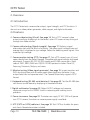
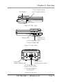
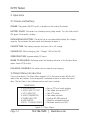
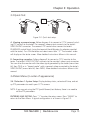
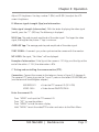
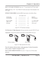
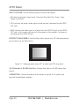
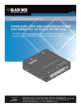
June 2010 CCTVTEST CCTV Tester Tests camera video output, signal strength, and BLACK BOX PTZ functions. Also acts as a video pattern generator, cable mapper, and multimeter. ® Customer Support Information Order toll-free in the U.S.: Call 877-877-BBOX (outside U.S. call 724-746-5500) • FREE technical support 24 hours a day, 7 days a week: Call 724-746-5500 or fax 724-746-0746 • Mailing address: Black Box Corporation, 1000 Park Drive, Lawrence, PA 15055-1018 Web site: www.blackbox.com • E-mail: [email protected] CCTV Tester FEDERAL COMMUNICATIONS COMMISSION AND INDUSTRY CANADA RADIO FREQUENCY INTERFERENCE STATEMENTS This equipment generates, uses, and can radiate radio-frequency energy, and if not installed and used properly, that is, in strict accordance with the manufacturer’s instructions, may cause interference to radio communication. It has been tested and found to comply with the limits for a Class A computing device in accordance with the specifications in Subpart B of Part 15 of FCC rules, which are designed to provide reasonable protection against such interference when the equipment is operated in a commercial environment. Operation of this equipment in a residential area is likely to cause interference, in which case the user at his own expense will be required to take whatever measures may be necessary to correct the i nterference. Changes or modifications not expressly approved by the party responsible for compliance could void the user’s authority to operate the equipment. This digital apparatus does not exceed the Class A limits for radio noise emission from digital apparatus set out in the Radio Interference Regulation of Industry Canada. Le présent appareil numérique n’émet pas de bruits radioélectriques dépassant les limites applicables aux appareils numériques de classe A prescrites dans le Règlement sur le brouillage radioélectrique publié par Industrie Canada. Normas Oficiales Mexicanas (NOM)Electrical Safety Statement INSTRUCCIONES DE SEGURIDAD 1. Todas las instrucciones de seguridad y operación deberán ser leídas antes de que el aparato eléctrico sea operado. Page 2 724-746-5500 | blackbox.com NOM Statement 2. Las instrucciones de seguridad y operación deberán ser guardadas para referencia futura. 3. Todas las advertencias en el aparato eléctrico y en sus instrucciones de operación deben ser respetadas. 4. Todas las instrucciones de operación y uso deben ser seguidas. 5. El aparato eléctrico no deberá ser usado cerca del agua—por ejemplo, cerca de la tina de baño, lavabo, sótano mojado o cerca de una alberca, etc. 6. El aparato eléctrico debe ser usado únicamente con carritos o pedestales que sean recomendados por el fabricante. 7. El aparato eléctrico debe ser montado a la pared o al techo sólo como sea recomendado por el fabricante. 8. Servicio—El usuario no debe intentar dar servicio al equipo eléctrico más allá a lo descrito en las instrucciones de operación. Todo otro servicio deberá ser referido a personal de servicio calificado. 9. El aparato eléctrico debe ser situado de tal manera que su posición no interfiera su uso. La colocación del aparato eléctrico sobre una cama, sofá, alfombra o superficie similar puede bloquea la ventilación, no se debe colocar en libreros o gabinetes que impidan el flujo de aire por los orificios de ventilación. 10. El equipo eléctrico deber ser situado fuera del alcance de fuentes de calor como radiadores, registros de calor, estufas u otros aparatos (incluyendo amplificadores) que producen calor. 11. El aparato eléctrico deberá ser connectado a una fuente de poder sólo del tipo descrito en el instructivo de operación, o como se indique en el aparato. 12. Precaución debe ser tomada de tal manera que la tierra fisica y la polarización del equipo no sea eliminada. 13. Los cables de la fuente de poder deben ser guiados de tal manera que no sean pisados ni pellizcados por objetos colocados sobre o contra ellos, poniendo particular atención a los contactos y receptáculos donde salen del aparato. 724-746-5500 | blackbox.com Page 3 CCTV Tester 14. El equipo eléctrico debe ser limpiado únicamente de acuerdo a las recomendaciones del fabricante. 15. En caso de existir, una antena externa deberá ser localizada lejos de las lineas de energia. 16. El cable de corriente deberá ser desconectado del cuando el equipo no sea usado por un largo periodo de tiempo. 17. Cuidado debe ser tomado de tal manera que objectos liquidos no sean derramados sobre la cubierta u orificios de ventilación. 18. Servicio por personal calificado deberá ser provisto cuando: A: El cable de poder o el contacto ha sido dañado; u B: Objectos han caído o líquido ha sido derramado dentro del aparato; o C: El aparato ha sido expuesto a la lluvia; o D: E l aparato parece no operar normalmente o muestra un cambio en su desempeño; o E: El aparato ha sido tirado o su cubierta ha sido dañada. Page 4 724-746-5500 | blackbox.com Trademarks Used in this Manual Trademarks Used in this Manual Black Box and the Double Diamond logo are registered trademarks of BB Technologies, Inc. Any other trademarks mentioned in this manual are acknowledged to be the property of the trademark owners. 724-746-5500 | blackbox.com Page 5 CCTV Tester Safety Information Precautions when using the CCTV Tester A. Please read this manual before using the product. B. Always be cautious when working around voltage. C. Do not use the tester in damp or explosive environments. D. Areas of strong electromagnetism can cause incorrect measurements. E. Do not expose the tester to dirt or liquid. F. Do not disassemble the tester. G. Operating environment: Temperature: -22 to 158° F (-30 to +70° C) Relative humidity: 30 to 90% Recharging voltage:5 VDC Precautions when charging the battery A. Use only the original, chargeable battery that came with the tester. When charging, use the original power adapter. B. Make sure the batteries are installed correctly (polarity). C. Do not short-circuit or disassemble batteries. Page 6 724-746-5500 | blackbox.com Table of Contents Table of Contents 1. Specifications ........................................................................................... 8 2. Overview ......................................................................................... 10 2.1 Introduction................................................................................... 10 2.2 Features......................................................................................... 10 2.3 What’s Included..............................................................................11 2.4 Hardware Description.....................................................................11 3. Operation ......................................................................................... 14 3.1 Power and Battery......................................................................... 14 3.2 Main Menu Introduction............................................................... 14 3.3 Quick Test....................................................................................... 15 3.4 Main Menu.................................................................................... 15 3.4.1 System Setup.................................................................... 15 3.4.2 Video, Signal Strength, and PTZ Test............................... 16 3.4.3 UTP Cable Testing............................................................ 18 3.4.4 Video Generator.............................................................. 19 3.4.5 RS-485 Data Test............................................................. 20 3.4.6 Multimeter....................................................................... 22 3.5 Provide Power to a 12V Camera.................................................... 23 3.6 Screen Brightness Adjustment....................................................... 23 724-746-5500 | blackbox.com Page 7 CCTV Tester 1. Specifications Table 1-1. CCTV Tester specifications. Feature Video testing Description Signal mode NTSC/PAL compatible LCD display 2.5" LCD screen, 960 x 240 resolution Signal strength Max. Vpp, ave. Vpp, and Sync V Video input 1 channel BNC Video output 1 channel BNC LCD brightness Adjustable from keypad Communication protocol RS-232, RS-422 simplex and RS-485 Includes 20 manufacturer’s protocols Baud rate 2400, 4800, 9600, 19200 DC voltage test AC voltage test Max.: 1000 V, Precision: 0.1 mV Max: 750 V, Precision: 0.1 mV Resistance test Max.: 40 Mohm, Precision: 0.1 ohm PTZ test and control Built-in multimeter Power to camera Voltage 12 VDC Working time 4-5 hours to normal camera Max. current 200 mA UTP cable test Test UTP (CAT5/6) cables Signal generator Test security monitors RS-485 data test Display RS-485 data from device OSD menu English OSD menu Keypad Easy to operate. Uses number buttons. Other functions Power and battery Power adapter 5 VDC Battery 3000 mAh rechargeable battery inside Rechargeable 6 hours recharging time Low consumption Sleep mode. Power status display. Operating time 10 hours Page 8 724-746-5500 | blackbox.com Chapter 1: Specifications Table 1-1 (Continued). CCTV Tester specifications. Other Feature Work humidity Size Description Work temperature Weight -22 to +158° F (-30 to +70° C) 30 to 90% 6.5"H x 3.6"W x 1.9"D (16.6 x 9.1 x 4.8 cm) 0.6 lb. (0.3 kg) 724-746-5500 | blackbox.com Page 9 CCTV Tester 2. Overview 2.1 Introduction The CCTV Tester tests camera video output, signal strength, and PTZ functions. It also acts as a video pattern generator, cable mapper, and digital multimeter. 2.2 Features A. Camera video testing (Visual). See page 16. Test a CCTV camera’s video output visually by displaying it on the tester’s color LCD screen or loop the signal through to a video monitor. B. Camera video testing (Signal strength). See page 17. Perform a signal attenuation test with the touch of a button. The video signal’s voltage (max and average Vpp) is displayed as sync voltage. Perfect for detecting weak signals. Also measures sync voltage. C. Camera motion testing (PTZ). See page 17. Test a PTZ camera’s pan, tilt, and zoom directly from the tester’s keypad. Complete with preset settings and speed adjustment. Supports RS-232, RS-422 simplex and RS-485 connections. Baud rates of 2400, 4800, 9600 and 19,200. RS-485 protocol includes: Pelco D,P, Samsung, Panasonic, Molynx, and more. D. Monitor testing (Video signal generator). See page 15. Inspect monitors and DVRs by driving them with a known good video signal from the tester. It can output color bars and separate colors. The Camera Wizard only supports NTSC format. E. Keyboard testing (RS-485 serial data test). See page 20. Test the RS-485 data sent from a control device by displaying its hexadecimal data. F. Digital multimeter. See page 22. Detect AC/DC voltages and measure resistance using a built-in DMM. Useful in measuring and isolating circuit problems. G. Power to camera. See page 23. The tester can supply 12 VDC (200 mA) power to a CCTV camera. Use when no camera power supply is available. H. UTP (CAT5 or CAT6) cable test. See page 18. Test CAT5 or 6 cables for opens and shorts. Remote terminator included. Page 10 724-746-5500 | blackbox.com Chapter 2: Overview 2.3 What’s Included Your package should include the following items. If anything is missing or damaged, contact Black Box Technical Support art 724-746-5500 or [email protected]. • CCTV Tester with rechargeable battery • Charger • UTP cable terminator • BNC connect cable • BNC to RCA adapter • PTZ terminal block/alligator adapter • DMM test leads • Lanyard • 12-VDC power cable • This user’s manual 2.4 Hardware Description Figures 2-1 through 2-4 illustrate the CCTV Tester and describe its components. 724-746-5500 | blackbox.com Page 11 CCTV Tester Data transmit (PTZ data): Lights Charge LED: when when transmitting on, tester is charging data Data receive (PTZ data): Lights when receiving data Open: Open camera iris (PTZ test); Set: A multipurpose button used to start or enable functions 2.5" LCD screen: 960 x 240 resolution Close/Clear: Close camera and clear setup (PTZ test) Tele: Zooms IN lens (PTZ test); switches generated video to Video Out jack (Video Generator test) Menu: Hold to return to the Main Menu Max. Vpp, Average Vpp, and sync signal: Press during video test for quick, accurate signal analysis Wide: Zooms Out lens (PTZ test); switches generated video to tester display (Video Generator test) Arrow keys: Move camera up, down, right, left (PTZ test). Also menu cursor control Far: Focus lens to far (PTZ test) Near: Focus lens to near (PTZ test) 0–9 number keys: Input numbers for PTZ function P=PST (Call Preset): Recall stored PTZ position (PTZ test) ADDR (address): Set up a PTZ ID (PTZ test Page 12 Power: Lights when power is on Figure 2-1. Faceplate. S-PST (Setup Preset): Setup a preset PTZ position (PTZ test) 724-746-5500 | blackbox.com Chapter 2: Overview 12 VDC power output jack: to power camera RS-232 port Figure 2-2. Side 1 view. CAT5/6 UTP cable test jack 5-VDC power input jack: Connect charger here Power on/off Figure 2-3. Side 2 view. Video output: Video input: connect monitor here connect camera here RS-422/RS-485 port: Connect PTZ to +T and -T; Connect keyboard to +R and -R Figure 2-4. Top view. 724-746-5500 | blackbox.com Page 13 CCTV Tester 3. Operation 3.1 Power and Battery POWER: The power ON/OFF switch is located on the side of the tester. BATTERY SAVER: The tester has a battery-saving sleep mode. Turn the slide switch ON again if the tester is asleep. RECHARGEABLE BATTERY: The tester has a non-removable battery for a larger capacity. Do not open the rear panel and attempt to repair it. CHARGE TIME: The battery requires five hours for a full charge. CHARGE LED: While charging, the “Charge” LED will be ON. OPERATING TIME: Approximately 10 hours. WHEN TO RECHARGE: Recharge when the battery indicator in the System Setup menu shows 25% or less. USE WHILE CHARGING: The tester can be used during charging. 3.2 Main Menu Introduction Turn on the device. The Main Menu appears: #1 is the setup mode. #2 thru #6 selects five test modes. Use the keypad’s numbered buttons to select the menu item. The last item is the software version and serial number. MAIN MENU 1 SYSTEM SETUP 2 VIDEO AND PTZ TEST 3 UTP CABLE TEST 4 VIDEO GENERATOR 5 RS485 DATA TEST 6 MULTIMETER VER:V1.11 S/N:08110910 > Set up PTZ and check battery > Test video and control PTZ > Test UTP cables > Test video monitors > Analyze RS-485 protocol > Measure voltage/resistance > Software version and S/N Figure 3-1. Main Menu. Page 14 724-746-5500 | blackbox.com Chapter 3: Operation 3.3 Quick Test A B Figure 3-2. Quick test setup. A. Viewing a camera image: Follow diagram A to connect a CCTV camera (including PTZ control) to the tester. The camera’s video output connects to the tester’s VIDEO IN BNC connector. The camera’s PTZ control wires connect to tester’s RS-485/422 control block (using the terminal block/alligator clip adapter provided with the tester). Turn ON the tester and select menu item “2.” The camera’s video will display on the tester screen. More detailed instructions follow in this manual. B. Connecting a monitor: Follow diagram B to connect a CCTV monitor to the tester. The tester’s VIDEO OUT BNC connects to the monitor’s video input connector. You can drive the monitor with the video signal generated by the tester (menu item #4, then TELE) or in “looped mode” with a camera’s video connected to the tester’s VIDEO IN BNC (menu item #4, then WIDE). More detailed instructions follow in this manual. 3.4 Main Menu (in order of appearance) 3.4.1 Selection 1: System Setup: Display battery status, set auto-off time, and set up PTZ parameters to match your CCTV camera. NOTE: If you are not using the PTZ (pan/tilt/zoom) test feature, there is no need to set the PTZ parameters. ENTERING AND EXITING: Press “1” to enter the setup screen. Press “MENU” to return to the Main Menu. A typical configuration is as shown in Figure 3-3. 724-746-5500 | blackbox.com Page 15 CCTV Tester PROTOCOL Pelco P COM 485 RATE 4800 SPEED 016 IDLE TIME 000 BATTERY 090 > PTZ protocol of camera > PTZ communication port type > PTZ baud rate: 2400/4800/9600/19200 > PTZ pan and tilt speed > Battery saver turn off time (minutes) > Battery status (%):100/90/75/50/25/5 Figure 3-3. Typical configuration. MODIFYING THE SETTINGS: ENTER SETUP MODE: Press “SET.” In this mode you 1) modify the PTZ settings (Protocol, Com, Rate and Speed) to match the camera you are testing and 2) set the battery saver turnoff time (when no activity). SELECT THE ITEM: Press the “UP and DOWN arrows” to blink the line you wish to modify. Battery status (% remaining) cannot be modified. ADJUST THE PARAMETER: Press the “UP/DOWN/RIGHT arrow.” SAVE/EXIT. Press the “LEFT arrow” to save the setting. Press the “LEFT arrow” again to stop the blinking. Exit by holding the “MENU key” to return to the Main Menu. NOTE: T he CCTVTEST has 20 PTZ protocols and 17 speed settings (1 is the slowest and 16 is the fastest). 3.4.2 Selection 2: Video, Signal Strength, and PTZ Test A. Display a camera’s video signal on the LCD and monitor: CONNECTION: Connect the camera to the tester as shown in Figure 3-1. The camera connects to the tester’s VIDEO IN jack. Display camera video: Press “2” on the keypad to turn ON the tester’s video and PTZ feature. The camera’s video appears on the color LCD display. The camera’s video will also appear on a monitor (if connected to the tester’s VIDEO OUT jack). Study the image for proper focus and viewing angle. Study the voltage readout (below) for proper amplitude. And use the tester’s PTZ feature (below) to control pan, tilt, and zoom. Page 16 724-746-5500 | blackbox.com Chapter 3: Operation Adjust LCD brightness: Use keys number 7 (BR+) and 9 (BR-) to adjust the LCD screen’s brightness. B. Measure signal strength (Vpp) and attenuation: Video signal strength (attenuation): With the tester displaying the video signal (see A), press the “1” (IRE) key. The following is displayed: MAX Vpp: The peak-to-peak amplitude of the video signal. The larger the video signal, the brighter the picture. 1 Vpp is minimum. AVERAGE Vpp: The average peak-to-peak amplitude of the video signal. SYNC SIGNAL: A camera’s sync pulses synchronize the camera with the monitor. NO VIDEO: No signal, “No Video” will be displayed. Example of attenuation: If the Vpp at the camera is 1.25 Vpp, and the Vpp at the end of the cable is 1.15 V, the attenuation is 8%. C. Testing and controlling the camera motion (PTZ): Connection. Connect the camera to the tester as shown in Figure 3-2, diagram A. The camera’s PTZ wires plug into the T+ and T- ports on the tester’s RS-422/485 jack (use the terminal block/alligator adapter). ADDRESS:001 VIDEO: NULL > Enter the PTZ camera’s ID (001–255) > Video format PAL/NTSC/NULL Enter the camera’s ID. Press “ADDR” and input the PTZ camera’s ID. Press “SET” to save the address. Press “MENU” to hide the menu display. Hold “MENU” to exit the video/PTZ function and return to the Main Menu. 724-746-5500 | blackbox.com Page 17 CCTV Tester NOTE: S ee Section 3.4.1, System Setup to match the tester’s PTZ protocol, com type, and baud rate to that of the camera. Controlling the camera’s PTZ (pan/tilt/zoom): Press “UP/DOWN/LEFT/RIGHT” to control the movement. Press “OPEN/CLOSE” to control the iris. Press “FAR/NEAR” to adjust focus. Press “WIDE/TELE” to zoom the camera lens in and out. Saving and Calling Preset positions: The Video Wizard can Save and Call preset positions. To Save: Press “S-PST” and input a position number. Press “SET” to save. To Call: Press “C-PST” and input the position number. Press “SET” to call. Multiple preset positions can be saved. 3.4.3 Selection 3: UTP Cable Testing: Testing a UTP cable (CAT5/6) for proper connection. NOTE: “ UTP” means unshielded twisted pair. UTP is the most common type of CAT5 and 6 cable. CONNECTION: Connect the CAT5/6 UTP cable to the UTP TEST socket on the right side of the tester. Connect the Remote Terminator to the far end of the cable. Testing a CAT5 or CAT6 cable (UTP) Remote terminator Figure 3-4. Testing UTP cable setup. Page 18 724-746-5500 | blackbox.com Chapter 3: Operation SELECT UTP CABLE TEST MODE: Press the “3” key to enter the UTP test mode. START TEST: Press “SET.” The CAT5/6 UTP cable wire map will be displayed on the LCD screen. RETURN TO MAIN MENU: Hold the MENU key to return to the Main Menu. TESTER SIDE PIN NUMBERS Typical CAT5/6 Cable (UTP) Wiremap 1 2 3 4 5 6 7 8 UTP CABLE TEST ----------------------- ----------------------- ----------------------- ----------------------- ----------------------- ----------------------- ----------------------- ----------------------- 1 2 3 0 0 6 7 8 REMOTE PIN NUMBERS ”0” means open Two “0”s is a short circuit Figure 3-5. UTP cable test wiremap. 3.4.4 Selection 4: Video Generator: Testing a monitor using the VIDEO OUT port. Connection. Connect the monitor to the tester using the VIDEO OUT jack: Without camera With camera Figure 3-6. Video generator test setup. Drive the monitor with the tester’s video generator. Or drive the monitor with a camera “looped” through the tester. SELECT VIDEO GENERATOR MODE: Press the “4” key to turn ON the video generator. 724-746-5500 | blackbox.com Page 19 CCTV Tester SELECT OPTIONS: Use the following keys to control the options: • SET selects the tester’s video signal: Color bar, Blue, Red, Pink, Green, Cyan, Yellow, and White. • TELE switches the tester’s video signal to the monitor (connected to the VIDEO OUT jack). • WIDE switches the video signal so it loops from the VIDEO IN jack to the VIDEO OUT jack. In this mode, a picture will only appear on the monitor if a camera is connected to the VIDEO IN jack. ETURN TO MAIN MENU: Hold the Main Menu key to turn OFF the video generaR tor and return to the Main Menu. Figure 3-7. Video generator (press SET to select and TELE to output). 3.4.5 Selection 5: RS-485 Data Test: Analyze data from an RS-485 device (keyboard). CONNECTION. Connect the device to the tester using the +R -R sockets (use terminal block/alligator adapter). Page 20 724-746-5500 | blackbox.com Chapter 3: Operation Figure 3-8. RS-485 keyboard test setup. Display the device’s hexadecimal output on the tester’s LCD. SELECT THE DATA TEST MODE: Press the “5” key to turn ON the RS-485 protocol analyzer. SELECT OPTIONS: Use the following keys to control the options: • SET enables the changing of the Baud rate. • UP/DOWN ARROW KEYS change the tester’s Baud rate. Select the Baud rate that matches the device that is being analyzed. Data transfer will start automatically through the RS-485 port. The hexadecimal data is displayed on the tester’s screen as shown below. Analysis of the data will indicate its protocol. RETURN TO MAIN MENU: Hold the Main Menu key to turn OFF the data flow and return to the Main Menu. A0 00 01 00 00 00 AF 0F A0 00 01 00 00 00 AF 0E A0 00 01 00 00 00 AF 0F A0 00 01 00 00 00 AF 4F A0 00 01 00 00 00 AF EF A0 00 01 00 00 00 AF 2F Figure 3-9. Typical hexadecimal data from an RS-485 device. 724-746-5500 | blackbox.com Page 21 CCTV Tester 3.4.6 Selection 6: Multimeter. Use the tester as a digital multimeter to measure AC/DC voltage and resistance. NOTE: T he tester displays the Vpp of the video signal and sync signal on the LCD without the use of the test leads. See Menu Item #4 on page 14. CONNECTION: Connect the 2 test leads to the bottom of the tester as shown in Figure 3-10. Figure 3-10. DMM test leads attached to bottom of tester. SELECT MULTIMETER MODE: Press “6” on the keypad to turn ON the DMM (digital multimeter). DC: 121.3 MV 1 DC VOLTAGE 2 AC VOLTAGE 3 RESISTANCE Figure 3-11. Digital multimeter menu. SELECT FUNCTION: Press key 1, 2 or 3. DC voltage test range: 0-1000 V, precision: 0.1 mV AC voltage test range: 750 V, precision: 0.1 mV Resistance test range: 0-40 Mohm , precision: 0.1 ohm RETURN TO MAIN MENU: Hold the Main Menu key to return to the Main Menu. NOTE: Exercise caution when voltage is present. If you are not familiar with proper safety techniques, ask for guidance. Do not exceed the testing range (above) or damage may occur. Page 22 724-746-5500 | blackbox.com Chapter 3: Operation 3.5 Provide Power to a 12V Camera The tester can be used to provide power to a 12V camera. CONNECTION: Connect the cable (included) to the tester’s “DC 12V OUTPUT” jack (on the left side of the tester). Connect the other end to the camera’s 12-VDC power input jack. Use only with 12 VDC cameras (200 ma max.). WORKING TIME: The amount of time that the tester powers the camera depends on the camera’s power consumption. If the camera draws less than 100 mA, the tester will power the camera for about four hours. MAXIMUM CURRENT/POWER: The maximum output current from the tester is 200 mA/2400 milliwatts. NOTES: 1. The output voltage of tester is DC12V. Please only connect it to 12V cameras. 2. Do not connect the tester’s DC12V output to the tester’s own 5-VDC input jack. This will damage the tester. Power connected to camera Figure 3-12. Powering a 12 V camera. 3.6 Screen Brightness Adjustment When in the Video and PTZ testing mode (menu item #2) use key number 7 (BR+) and key number 9 (BR-) to adjust the screen’s brightness. 724-746-5500 | blackbox.com Page 23 Black Box Tech Support: FREE! Live. 24/7. Tech support the way it should be. Great tech support is just 20 seconds away at 724-746-5500 or blackbox.com. About Black Box Black Box Network Services is your source for more than 118,000 networking and infrastructure products. You’ll find everything from cabinets and racks and power and surge protection products to media converters and Ethernet switches all supported by free, live 24/7 Tech support available in 20 seconds or less. © Copyright 2010. All rights reserved.