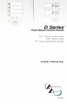
1
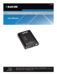
Black Box Tech Support: FREE! Live. 24/7. Tech support the way it should be. Great tech support is just 20 seconds away at 724-746-5500 or blackbox.com. About Black Box Black Box Network Services is your source for more than 118,000 networking and infrastructure products. You’ll find everything from cabinets and racks and power and surge protection products to media converters and Ethernet switches all supported by free, live 24/7 Tech support available in 20 seconds or less. © Copyright 2009. All rights reserved. 724-746-5500 | blackbox.com May 2009 AC1124A AC1125A DVI Matrix Switches Ideal for digital signage! Simplifies signal routing. BLACK BOX ® The AC1124A model routes a video and audio signal from 2 DVI sources (computers, media players, TV tuners, etc.) to 4 DVI displays (projectors, monitors, and so on) and speakers. The AC1125A model routes a video and audio signal from 4 DVI sources to 2 DVI displays and speakers. Control the switch via a wireless remote control within an 11-foot range. Customer Support Information Order toll-free in the U.S.: Call 877-877-BBOX (outside U.S. call 724-746-5500) • For FREE technical support 24 hours a day, 7 days a week: Call 724-746-5500 or fax 724-746-0746 • Mailing address: Black Box Corporation, 1000 Park Drive, Lawrence, PA 15055-1018 • Web site: www.blackbox.com • E-mail: [email protected] FCC and NOM Statements FEDERAL COMMUNICATIONS COMMISSION AND INDUSTRY CANADA RADIO FREQUENCY INTERFERENCE STATEMENTS This equipment generates, uses, and can radiate radio-frequency energy, and if not installed and used properly, that is, in strict accordance with the manufacturer’s instructions, may cause interference to radio communication. It has been tested and found to comply with the limits for a Class A computing device in accordance with the specifications in Subpart B of Part 15 of FCC rules, which are designed to provide reasonable protection against such interference when the equipment is operated in a commercial environment. Operation of this equipment in a residential area is likely to cause interference, in which case the user at his own expense will be required to take whatever measures may be necessary to correct the i nterference. Changes or modifications not expressly approved by the party responsible for compliance could void the user’s authority to operate the equipment. This digital apparatus does not exceed the Class A limits for radio noise emission from digital apparatus set out in the Radio Interference Regulation of Industry Canada. Le présent appareil numérique n’émet pas de bruits radioélectriques dépassant les limites applicables aux appareils numériques de classe A prescrites dans le Règlement sur le brouillage radioélectrique publié par Industrie Canada. Normas Oficiales Mexicanas (NOM)Electrical Safety Statement INSTRUCCIONES DE SEGURIDAD 1. Todas las instrucciones de seguridad y operación deberán ser leídas antes de que el aparato eléctrico sea operado. 2. Las instrucciones de seguridad y operación deberán ser guardadas para referencia futura. 3. Todas las advertencias en el aparato eléctrico y en sus instrucciones de operación deben ser respetadas. 724-746-5500 | blackbox.com Page 1 DVI Matrix Switches 4. Todas las instrucciones de operación y uso deben ser seguidas. 5. El aparato eléctrico no deberá ser usado cerca del agua—por ejemplo, cerca de la tina de baño, lavabo, sótano mojado o cerca de una alberca, etc. 6. El aparato eléctrico debe ser usado únicamente con carritos o pedestales que sean recomendados por el fabricante. 7. El aparato eléctrico debe ser montado a la pared o al techo sólo como sea recomendado por el fabricante. 8. Servicio—El usuario no debe intentar dar servicio al equipo eléctrico más allá a lo descrito en las instrucciones de operación. Todo otro servicio deberá ser referido a personal de servicio calificado. 9. El aparato eléctrico debe ser situado de tal manera que su posición no interfiera su uso. La colocación del aparato eléctrico sobre una cama, sofá, alfombra o superficie similar puede bloquea la ventilación, no se debe colocar en libreros o gabinetes que impidan el flujo de aire por los orificios de ventilación. 10.El equipo eléctrico deber ser situado fuera del alcance de fuentes de calor como radiadores, registros de calor, estufas u otros aparatos (incluyendo amplificadores) que producen calor. 11. El aparato eléctrico deberá ser connectado a una fuente de poder sólo del tipo descrito en el instructivo de operación, o como se indique en el aparato. 12. Precaución debe ser tomada de tal manera que la tierra fisica y la polarización del equipo no sea eliminada. 13. Los cables de la fuente de poder deben ser guiados de tal manera que no sean pisados ni pellizcados por objetos colocados sobre o contra ellos, poniendo particular atención a los contactos y receptáculos donde salen del aparato. 14.El equipo eléctrico debe ser limpiado únicamente de acuerdo a las recomendaciones del fabricante. 15. En caso de existir, una antena externa deberá ser localizada lejos de las lineas de energia. Page 2 724-746-5500 | blackbox.com NOM Statement 16.El cable de corriente deberá ser desconectado del cuando el equipo no sea usado por un largo periodo de tiempo. 17. Cuidado debe ser tomado de tal manera que objectos liquidos no sean derramados sobre la cubierta u orificios de ventilación. 18.Servicio por personal calificado deberá ser provisto cuando: A: El cable de poder o el contacto ha sido dañado; u B: Objectos han caído o líquido ha sido derramado dentro del aparato; o C: El aparato ha sido expuesto a la lluvia; o D: El aparato parece no operar normalmente o muestra un cambio en su desempeño; o E: El aparato ha sido tirado o su cubierta ha sido dañada. 724-746-5500 | blackbox.com Page 3 DVI Matrix Switches TRADEMARKS USED IN THIS MANUAL Black Box and the Double Diamond logo are registered trademarks of BB Technologies, Inc. Any other trademarks mentioned in this manual are acknowledged to be the property of the trademark owners. Page 4 724-746-5500 | blackbox.com Table of Contents Chapter Page 1. Specifications.........................................................................................................6 2. Overview .........................................................................................................7 2.1 Introduction..................................................................................................7 2.2 What’s Included............................................................................................7 2.3 Features.........................................................................................................8 2.4 Front Panel....................................................................................................9 2.5 Rear Panel...................................................................................................10 3. Installation (AC1124A).......................................................................................12 3.1 Input Connection........................................................................................12 3.2 Output Connection.....................................................................................14 4. Installation (AC1125A).......................................................................................17 4.1 Input Connection........................................................................................17 4.2 Output Connection.....................................................................................20 5. Basic Operation (AC1124A)................................................................................21 5.1 Front Panel..................................................................................................21 Route Source 1 or Source 2 to Monitors 1 through 4................................21 5.2 Remote Control...........................................................................................22 Route Source 1 or Source 2 to Monitors 1 through 4................................22 6. Basic Operation (AC1125A)................................................................................24 6.1 Front Panel..................................................................................................24 Route Source 1 through 4 to Monitors 1 or 2............................................24 6.2 Remote Control...........................................................................................25 Route Source 1 through 4 to Monitors 1 or 2............................................25 6.3 Serial Control..............................................................................................28 7. Advanced Operation (AC1124A or AC1125A)...................................................35 7.1 Front Panel..................................................................................................35 7.1.1 Turn the Video On/Off...................................................................35 7.1.2 Turn the Audio On/Off..................................................................36 7.1.3 Turn the Auto Scan On/Off...........................................................37 7.1.4 Set the Auto Scan Time Interval....................................................38 7.1.5 Restore Default Settings.................................................................38 7.2 Unit Stack.....................................................................................................39 7.2.1 Set the Remote Control ID on the System.....................................39 7.2.2 Optimize the Video Signal Strength (for AC1124A Only)..............39 7.2.3 Copy the EDID to the Video Matrix Switch.................................. 40 8. Rackmount Kit (Optional) and Multi-Mode Sensor Kits....................................41 724-746-5500 | blackbox.com Page 5 DVI Matrix Switches 1. Specifications Automatic Scan Interval: 8, 15, 30, 45 seconds DVI Cable Length (Max): 16.4 ft. (5 m) Operating Temperature: 41 to 104–176° F (5 to 40–176° C) Resolution Supported (Maximum): 1600 x 1200 at 60 Hz CE Approval: Yes Connectors: AC1124A: Input: (2) DVI-I, (2) 3.5-mm stereo; Output: (4) DVI-I, (4) 3.5-mm stereo; AC1125A: Input (4) DVI-I, (4) 3.5-mm stereo; Output: (2) DVI-I, (2) 3.5-mm stereo NOTE: The analog pins of these DVI-I connectors are not passed through the switch. The DVI-I connectors are used solely to ensure cable compatibility. Power: Input: 100–240 VAC, 50–60 Hz, autosensing; Output: 12V DC, 1.5A; Remote: Auxiliary power Size: 1.6"H (1U) x 8.7"W x 3.8"D (4.1 x 22 x 9.7 cm) Weight: 1.6 lb. (0.7 kg) Page 6 724-746-5500 | blackbox.com Chapter 2: Overview 2. Overview 2.1 Introduction The 2 x 4 Video Matrix Switch with Audio (AC1124A) routes the video signal and audio signal from 2 DVI sources (computers, media players, TV tuners, etc.) to 4 DVI displays (projectors, monitors, and so on) and 4 speakers. The 4 x 2 Video Matrix Switch with Audio (AC1125A) routes the video signal and audio signal from 4 DVI sources to 2 DVI displays (projectors, monitors, and so on) and 2 speakers. Use the switch as part of a video/audio signal management system in presentation applications to simplify the process of handling signal routing. Control the switch via a wireless remote control unit within the range of 11 feet (5 meters). The switch distributes signals from a range of input sources to various output devices, in essence creating a “matrix” pattern of interconnection possibilities. The switch can route a single computer video output and audio output to one or more monitors and speakers. Each image will be as crisp and clear as if directly connected to the original source. Plus, each video output and audio output is buffered from each input, ensuring signal integrity throughout the system. Use this switch in applications where information from 2 or 4 DVI computers is being presented such as: • Presentations • Classrooms • Exhibits • Trade shows • Business meetings • Entertainment facilities • Courtrooms • Monitor tests • Monitor burn-ins • Command centers • Control rooms 2.2 What’s Included Your package should include the following items. If anything is missing or damaged, contact Black Box Tech Support at 724-746-5500. • 2 x 4 or 4 x 2 DVI Matrix Switch with Audio • Power adapter • AC cord • This user’s manual 724-746-5500 | blackbox.com Page 7 DVI Matrix Switches • Serial Control Cable (2.5-mm plug to DB9 female) (for AC1125A only) • Remote controller • IR Extension Kit (includes [1] mounting plate [magnetic or screw-mount], [1] pivoting sensor holder, [1] 6-foot remote placement cable, and [2] screws) • Set of rubber foot pads 2.3 Features • Routes 2 or 4 different DVI signals as well as the audio sources to 4 or 2 different DVI displays and speakers. • Remote control from up to 11 feet (5 meters) away from the switch. • Switches both video and audio simultaneously. • Supports turning ON/OFF the video of each individual output port respectively. • Supports turning ON/OFF the audio of each individual output port respectively. • Multiple outputs do not cause distortion. • Front buttons for easy switching. • Press front buttons to activate Auto Scan. • Selectable Scan Time interval. • Buzzer sound confirms switching. • Cascade Video Matrix Switches and control them via a single remote controller. • Exclusively control up to 16 switches remotely by using one single remote controller; a unique code is assignable for each unit. • Auto scan is available. • Connect each input independently to any or all outputs. • Each output provides one video signal and one audio signal. • Supports video resolution of 1600 x 1200. • No additional hardware or software is needed. • System settings are automatically retained. Recover your previous settings after power blackouts. Page 8 724-746-5500 | blackbox.com Chapter 2: Overview 2.4 Front Panel Figures 2-1 and 2-2 show the front panel of the 2 x 4 DVI Matrix Switch (AC1124A) and the 4 x 2 DVI Matrix Switch (AC1125A). Table 2-1 describes both switches’ components. 1 2 1 Figure 2-1. AC1124A front panel. 1 2 1 Figure 2-2. AC1125A front panel. Table 2-1. Front panel components. Number Component Description 1 Buttons and LEDs 1–4Press the button to select a port. LED functions are described in Chapters 4–7. 2 Option button and LEDLED and option button functions are described in Chapters 4–7. 724-746-5500 | blackbox.com Page 9 DVI Matrix Switches 2.5 Rear Panel Figures 2-3 and 2-4 show the switch’s rear panels. Tables 2-2 and 2-3 describe the components. 1 2 5 2 4 3 Figure 2-3. AC1124A rear panel. Table 2-2. AC1124A rear panel components. Number Component Description 1 Source 1 and Source 2 connectors (2) DVI-I 2 Source 1 and Source 2 audio connectors (2) 3.5-mm stereo 3 Monitors 1, 2, 3, and 4 connectors (4) DVI-I 4 5 Monitors 1, 2, 3, and 4 audio connectors (4) 3.5-mm stereo Remote control sensor connector 2.5-mm jack Page 10 724-746-5500 | blackbox.com Chapter 2: Overview 1 2 5 2 4 6 3 Figure 2-4. AC1125A rear panel. Table 2-3. AC1125A rear panel components. Number Component Description 1 Monitors 1 and 2 connectors (2) DVI-I 2 Monitors 1 and 2 audio connectors (2) 3.5-mm stereo 3 Source 1, 2, 3, and 4 connectors (4) DVI-I 4 Source 1, 2, 3, and 4 audio connectors (4) 3.5-mm stereo 5 Remote control sensor connector 2.5-mm jack 6 Auxiliary port 2.5-mm jack 724-746-5500 | blackbox.com Page 11 DVI Matrix Switches 3. Installation (AC1124A) Follow these steps to install the 2 x 4 DVI Matrix Switch (AC1124A). 3.1 Input Connection 1. Connect the source’s DVI video port to the switch’s source 1 video port. See Figure 3-1. AC1124A Source 1 Computer DVI video port Figure 3-1. Attaching the source’s DVI port to the switch’s source 1 video port. Page 12 724-746-5500 | blackbox.com Chapter 3: Installation (AC1124A) 2. Connect the source’s speaker port to the switch’s source 1 audio port. See Figure 3-2. Source 1 audio port AC1124A Computer speaker port Source 1 DVI video port Figure 3-2. Linking the source’s speaker port to the switch’s source 1 audio port. 3. Repeat Steps 1 and 2 for source 2. See Figure 3-3. AC1124A Source 2 audio port Source 2 Computer speaker port DVI video port Figure 3-3. Connections for source 2. 724-746-5500 | blackbox.com Page 13 DVI Matrix Switches 3.2 Output Connection 1. Connect your monitor 1 to the switch’s video port 1. See Figure 3-4. Source 2 Source 1 DVI monitor 1 Figure 3-4. Attaching monitor 1 to switch’s video port 1. 2. Connect a pair of speakers to the switch’s audio port 1. See Figure 3-5. NOTE: Speakers may be integrated with the monitor or separate. Speakers Source 2 Source 1 Figure 3-5. Connecting speakers to audio port 1. Page 14 724-746-5500 | blackbox.com DVI monitor 1 Chapter 3: Installation (AC1124A) 3. Repeat Steps 1 and 2 for the switch’s video port 2 and audio port 2. See Figure 3-6. Speakers Source 2 DVI monitors 1 through 4 Source 1 Figure 3-6. Linking video port 2 and audio port 2. 724-746-5500 | blackbox.com Page 15 DVI Matrix Switches 4. Power on the switch. See Figure 3-7. Speakers Power connection Source 2 Source 1 Figure 3-7. Powering on the switch. Page 16 DVI monitors 1 through 4 724-746-5500 | blackbox.com Chapter 4: Installation (AC1125A) 4. Installation (AC1125A) Follow these steps to install the 4 x 2 DVI Matrix Switch (AC1125A). 4.1 Input Connection 1. Connect the source’s DVI video port to the switch’s source 1 video port. See Figure 4-1. AC1125A Source 1 Links to DVI video port Figure 4-1. Attaching the source’s DVI port to the switch’s source 1 video port. 724-746-5500 | blackbox.com Page 17 DVI Matrix Switches 2. Connect the source’s speaker port to the switch’s source 1 audio port. See Figure 4-2. Source 1 audio port AC1125A Source 1 DVI video port Figure 4-2. Linking the source’s speaker port to the switch’s source 1 audio port. Page 18 724-746-5500 | blackbox.com Computer speaker port Chapter 4: Installation (AC1125A) 3. Repeat Steps 1 and 2 for source 2. See Figure 4-3. Source 1 audio port Source 2 audio port Computer Computer speaker port speaker port Source Source 2 1 Figure 4-3. Connections for source 2. 724-746-5500 | blackbox.com Page 19 DVI Matrix Switches 4.2 Output Connection 1. Connect your monitor 1 to the switch’s video port 1. See Figure 4-4. 2. Connect a pair of speakers to the switch’s audio port 1. See Figure 4-4. NOTE: Speakers may be integrated with the monitor or separate. 3. Repeat Steps 1 and 2 for the switch’s video port 2 and audio port 2. See Figure 4-4. DVI monitor 2 Speakers Audio port 2 Video port 2 Power connection Video port 1 Audio port 1 Source 2 Source 1 Speakers DVI monitor 1 Figure 4-4. Connecting video and audio port 1 and port 2 output. 4. Power on the switch. Page 20 724-746-5500 | blackbox.com Chapter 5: Basic Operation (AC1124A) 5. Basic Operation (AC1124A) 5.1 Front Panel Once the unit is powered on, all four red LEDs will light. By default, the AC1124A switch routes source 1 to monitors 1 through 4. When all four LEDs are blinking, source 1 is empty or not detected. When all four LEDS are steady on, the switch detects the video signal from source 1. Route Source 1 or Source 2 to Monitor 1 through Monitor 4 1. Press the desired port button, for example, “4.” See Figure 5-1. Figure 5-1. Port 4 button. 2. LEDs “1” and “2” blink. See Figure 5-2. Figure 5-2. LEDs 1 and 2. “1” represents Source 1. “2” represents Source 2. “Green” means the video signal is detected. “Red” means NO video signal detected. 3. Press 1 or 2 within 3 seconds to select source 1 or source 2. After you select a source, the LED “4” will become either “red” or “orange.” “Red” means Source 1 is selected. “Orange” means Source 2 is selected. 4. Repeat Steps 1 through 3 for routing other ports. 724-746-5500 | blackbox.com Page 21 DVI Matrix Switches 5.2 Remote Control You can control the switch remotely in two ways. When the external sensor is not connected to the switch, the internal sensor works with the remote controller. When the external sensor is connected to the switch, the internal sensor is disabled, and the remote control works with the external sensor. Route Source 1 or Source 2 to Monitor 1 or Monitor 2 1. Connect the external sensor. See Figure 5-3. Figure 5-3. Connecting the external sensor. NOTE: For the AC1125A, only buttons “1” through “4” are activated. Buttons “5” through “16” are reserved for future models. 2. Press the desired port, for example, “4.” See Figure 5-4. Figure 5-4. Monitor 4 button on remote control. Page 22 724-746-5500 | blackbox.com Chapter 5: Basic Operation (AC1124A) 3. Press “S1“ or ”S2” to route source 1 or 2 to monitor 4 (M4). See Figure 5-5. Figure 5-5. S1/S2/S3/S4 buttons on the remote control. 4. Repeat Steps 1 and 3 for routing other ports. To turn the video or audio ON/OFF, simply press the “VIDEO” button or the “AUDIO” button. Figure 5-6. Video and audio buttons on the remote control. 724-746-5500 | blackbox.com Page 23 DVI Matrix Switches 6. Basic Operation (AC1125A) 6.1 Front Panel Once the unit is powered on, all four red LEDs will light. By default, the AC1125A routes source 1 to monitors 1 or 2. When all four LEDs are blinking, source 1 is empty or not detected. When all four LEDS are steady on, the switch detects the video signal from source 1. Route Source 1 through Source 4 to Monitor 1 or Monitor 2 1. Press the desired port button, for example, “4.” See Figure 5-1. Figure 6-1. Port 4 button. 2. All four LEDs blink. See Figure 5-2. Figure 6-2. LEDs 1 through 4. “1” represents Source 1. “2” represents Source 2. “3” represents Source 3. “4” represents Source 4. “Green” means the video signal is detected. “Red” means NO video signal detected. Page 24 724-746-5500 | blackbox.com Chapter 6: Basic Operation (AC1125A) 3. Press 1, 2, 3, or 4 within 3 seconds to select source 1 2, 3, or 4. After you select a source, the LED “2” will become either “red” or “orange.” “Red” means Source 1 is selected. “Orange” means Source 2 is selected. “Yellow” means Source 3 is selected. “Green” means Source 4 is selected. 4. Repeat Steps 1 through 3 for routing other ports. 6.2 Remote Control You can control the switch remotely in two ways. When the external sensor is not connected to the switch, the internal sensor works with the remote controller. When the external sensor is connected to the switch, the internal sensor is disabled, and the remote control works with the external sensor. Route Source 1 through Source 4 to Monitor 1 or Monitor 2 1. Connect the external sensor. See Figure 6-3. Figure 6-3. Connecting the external sensor. NOTE: For the AC1125A, only buttons “1” through “2” are activated. Buttons “3” through “16” are reserved for future models. 724-746-5500 | blackbox.com Page 25 DVI Matrix Switches 2. Press the desired port, for example, “2.” See Figure 6-4. Figure 6-4. Monitor 2 button on remote control. 3. Press “S1/S2/S3/S4” to route source 1/2/3/4 to monitor 2 (M2). See Figure 6-5. Figure 6-5. S1/S2/S3/S4 buttons on the remote control. Page 26 724-746-5500 | blackbox.com Chapter 6: Basic Operation (AC1125A) 4. Repeat Steps 1 and 3 for routing other ports. To turn the video or audio ON/OFF, simply press the “VIDEO” button or the “AUDIO” button. Figure 6-6. Video and audio buttons on the remote control. 724-746-5500 | blackbox.com Page 27 DVI Matrix Switches 6.3 Serial Control The DVI Matrix Switch’s built-in serial interface allows users to control the switch through a PC, serial controller devices, or home theater system. NOTE: Use a 2.5-mm plug to DB9 F connector cable (included). Configure the controller’s serial port as shown below: Baud rate: 9600 Data bits: 8 Parity: None Stop bits: 1 Flow control: None DVI Video & Stereo Radio Signal Management System Home Page V1.0.1 -------------------------------------------------------------------------Monitor 1 <-- Source 1 Video: ON Audio: ON Auto Scan: ON Monitor 2 <-- Source 1 Video: ON Audio: ON Auto Scan: OFF Source 1: Video Signal Detected. Source 2: No Video Signal Detected. Source 3: No Video Signal Detected. Source 4: No Video Signal Detected. Auto Scan Time Interval: 8 seconds. Remote Controlling ID: 1 ------------------------------------------------------------------------------------------------------------------------------------------------0. Display System Status. 1. Configure Monitor 1. 2. Configure Monitor 2. 9. Set Auto Scan Time Interval Choice: _ Figure 6-7. Configuration screen. Page 28 724-746-5500 | blackbox.com Chapter 6: Basic Operation (AC1125A) To select a source device via serial interface, select the number that corresponds to the port it is connected to as shown in Figure 6-8. -------------------------------------------------------------------------0. Display System Status 1. Configure Monitor 1. 2. Configure Monitor 2. 9. Set Auto Scan Time Interval. Choice: 1 Auto Scan Stopped. Monitor 1 <-- Source 1 Video: ON Auto Scan: OFF Monitor 1 Configuration. 0. Display System Status 1. Route Source 1 to Monitor 1. 2. Route Source 2 to Monitor 1. 3. Route Source 3 to Monitor 1.; 4. Route Source 4 to Monitor 1. 7. Set Video ON/OFF 8. Set Audio ON/OFF 9. Set Auto Scan ON/OFF Choice: Figure 6-8. Choosing a source device via the serial interface. 724-746-5500 | blackbox.com Page 29 DVI Matrix Switches Source 4: No Video Signal Detected. Auto Scan Time Interval: 8 seconds. Remote Controlling ID: 1 ---------------------------------------------------------------------------------------------------------------0. Display System Status. 1. Configure Monitor 1. 2. Configure Monitor 2. 9. Set Auto Scan Time Interval. Choice: 2 Monitor 2 Configuration. 0. Display System Status. 1. Route Source 1 to Monitor 2. 2. Route Source 2 to Monitor 2. 3. Route Source 3 to Monitor 2. 4. Route Source 4 to Monitor 2. 7. Set Video ON/OFF 8. Set Audio ON/OFF 9. Set Auto Scan ON/OFF Choice: Figure 6-9. Source 4 screen. Page 30 724-746-5500 | blackbox.com Chapter 6: Basic Operation (AC1125A) Source 1: Video Signal Detected. Source 2: No Video Signal Detected. Source 3: No Video Signal Detected. Source 4: No Video Signal Detected. Auto Scan Time Interval: 8 seconds. Remote Controlling ID: 1 ----------------------------------------------------------------------------------------------------------------------------------------------0. Display System Status 1. Configure Monitor 1. 2. Configure Monitor 2. 9. Set Auto Scan Interval. Choice: 9 Select Auto Scan Time interval 0. Display System Status 1. Represents 8 seconds. 2. Represents 15 seconds. 3. Represents 30 seconds. 4. Represents 45 seconds. Choice: _ Figure 6-10. Press “9” to set the scan time interval. 724-746-5500 | blackbox.com Page 31 DVI Matrix Switches Choice: 1 Monitor 1 Configuration. 0. Display System Status. 1. Route Source 1 to Monitor 1. 2. Route Source 2 to Monitor 1. 3. Route Source 3 to Monitor 1. 4. Route Source 4 to Monitor 1. 7. Set Video ON/OFF 8. Set Audio ON/OFF 9. Set Auto Scan ON/OFF Choice: 1 Monitor 1 <-- Source 1 Video: ON Audio: ON Auto Scan: OFF ------------------------------------------------------------------------0. Display System Status. 1. Configure Monitor 1. 2. Configure Monitor 2. 9. Set Auto Scan Time Interval. Choice: Figure 6-11. Route source 1 to monitor 1. Page 32 724-746-5500 | blackbox.com Chapter 6: Basic Operation (AC1125A) 1. Route Source 1 to Monitor 1. 2. Route Source 2 to Monitor 1.. 3. Route Source 3 to Monitor 1. 4. Route Source 4 to Monitor 1. 7. Set Video ON/OFF 8. Set Audio ON/OFF 9. Set Auto Scan ON/OFF Choice: 9 Monitor 1 <-- Source 1 Video: ON Audio: ON Auto Scan: ON Source 1: Video Signal Detected. Source 2: No Video Signal Detected. Source 3: No Video Signal Detected. Source 4: No Video Signal Detected. Auto Scan Time Interval: 8 seconds ------------------------------------------------------------------------------0. Display System Status. 1. Configure Monitor 1. 2. Configure Monitor 2. 9. Set Auto Scan Time Interval. Choice: _ Figure 6-12. Turn on the auto scan function. 724-746-5500 | blackbox.com Page 33 DVI Matrix Switches When a user plugs or unplugs the Matrix Switch’s DVI cable, the administrator can see it on the terminal window immediately. Source Status Changed. Source 1 text. -----------------------------------------0. Display System Status. 1. Configure Monitor 1. 2. Configure Monitor 2. 9. Set Auto Scan Time Interval. Choice: Source Status Changed: Source 3 Detected. ---------------------------------------------0. Display System Status. 1. Configure Monitor 1. 2. Configure Monitor 2. 9. Set Scan Time Interval. Choice: _ Figure 6-13. DVI cable plugged or unplugged status changed screen. Page 34 724-746-5500 | blackbox.com Chapter 7: Advanced Operation (AC1124A or AC1125A) 7. Advanced Operation (AC1124A or AC1125A) 7.1 Front Panel 7.1.1 Turn the Video ON/OFF 1. Press the desired port button, for example, “2.” Figure 7-1. Port button 2. 2. Press AND hold “Option.” LED 1 lights. LED 1: Green light means the monitor’s video output is turned on. Red light means it is turned off. Figure 7-2. Option button. 3. Press button “1” to turn OFF monitor 2’s video. Figure 7-3. Button 1: power off monitor. 4. If necessary, repeat steps 1 through 3 to turn ON monitor 2’s video. 724-746-5500 | blackbox.com Page 35 DVI Matrix Switches 7.1.2 Turn the Audio ON/OFF 1. Press the desired port, for example, “2.” Figure 7-4. Button 1: power off audio. 2. Press and hold “Option.” LED 2 lights. LED 2: Green light means the monitor’s audio output is turned on. Red light means it is turned off. Figure 7-5. Option button. 3. Press “2” to turn OFF monitor 1’s audio. Figure 7-6. Button 2: power off monitor 1’s audio. 4. If necessary, repeat steps 1 through 3 to turn another monitor’s audio ON. Page 36 724-746-5500 | blackbox.com Chapter 7: Advanced Operation (AC1124A or AC1125A) 7.1.3 Turn the AutoScan ON/OFF In this auto scan mode, the AC1124A switch automatically switches between source 1 to source 2 sequentially in a fixed interval for a particular monitor. 1. Press the desired port, for example, “4.” Figure 7-7. Port button 4. 2. Press AND hold “Option.” Figure 7-8. Option button. 3. Press “3” to turn ON the auto scan mode for monitor 4. Figure 7-9. Button 3: turn on autoscan for monitor 4. 4. If necessary, repeat steps 1 through 3 to turn OFF the auto scan mode of monitor 4. During the auto scan, you can press “4” to turn OFF monitor 4’s auto scan. If necessary, repeat steps 1 through 3 to turn ON the auto scan mode for another monitor. 724-746-5500 | blackbox.com Page 37 DVI Matrix Switches 7.1.4 Set the Auto Scan Time Interval 1. Press buttons “3” and “4” at the same time. Figure 7-10. Buttons 3 and 4. 2. When “1”, ”2”, ”3”, ”4” LEDs start blinking, press one of them to set the auto scan time interval. Figure 7-11. LEDs 1–4. “1” represents 8 seconds. “2” represents 15 seconds. “3” represents 30 seconds. “4” represents 45 seconds. 7.1.5 Restore Default Settings AC1124A: 1. Power OFF the switch. 2. Press AND hold “Option.” 3. Power ON the switch and press “1.” 4. Release “Option.” 5. Power OFF the switch again. 6. Power ON the unit to restore default settings. AC1125A: 1. Power OFF the switch. 2. Press AND hold “Option.” 3. Power ON the switch. 4. Press “1” to restore default settings. Page 38 724-746-5500 | blackbox.com Chapter 7: Advanced Operation (AC1124A or AC1125A) 7.2 Unit Stack This function allows the user to use one remote controller to control up to 16 switch units. 7.2.1 Set the Remote Control ID on the System 1. Power OFF the switch. 2. Press and hold “1” and “2” at the same time. 3. Power ON the switch. 4. Release “1” and “2.” 5. Select any one of the “1” through “16” remote control buttons on the remote control, for example, “4”. This sets the current switch remote control ID to 4. 6. To control this switch, press “SHIFT”+”4” on the remote controller. The unit with remote control ID 4 will beep twice and the Power LED will blink continuously. 7. Repeat steps 1 to 5 if there is more than 1 switch unit cascaded. NOTE: Each unit must be assigned a different remote control ID. More than one switch with the same ID will result in two switches receiving remote control commands simultaneously. The factory default remote control ID is 1. 7.2.2 Optimize the Video Signal Strength (for AC1124A Only) Adjust the optimal video signal strength corresponding to the length or quality of DVI cable since each monitor can be routed to one of the two input sources. As a result, each monitor has two different video strength settings. For example, if you want to change the video strength setting of source 2 for monitor 3, follow these steps: 1. Switch monitor 3 to source 2 (see Chapter 4 for details). 2. Press the desired port, for example, “3.” 3. Press AND hold “Option.” 4. Press “4” to turn ON the video signal strength setting mode for monitor 3. 5. Press “1” once or twice to adjust the selected port’s input video strength. LED 1 lights “green” to indicate normal strength or lights “red” to indicate enhanced strength. or ν Press “3” once or twice to adjust the selected port’s output current. LED 3 lights “green” to indicate normal current or lights “red” light to indicate enhanced current. or 724-746-5500 | blackbox.com Page 39 DVI Matrix Switches ν Press “4” one, two, three, or four times to adjust the selected port’s output priority. LED 4 lights “green” for no priority, lights “yellow” for low priority, lights “orange” for medium priority, or lights “red” for high priority. 5. Once you set the port’s priority, press the “Option” button to exit the setting 7.2.3 Copy the EDID to the Video Matrix Switch (for AC1125A Only) In some cases, display problems may occur because of incorrect EDID communication between the monitor and the PC graphics card or insufficient EDID data programmed by display manufacturers. Follow the steps below to copy the monitor’s EDID to the switch before operation. 1. Power OFF the AC1125A. 2. Press and hold buttons “3” and “4” simultaneously. 3. Power ON the AC1125A. 4. Release button “3” and “4” immediately after the switch is powered ON. 5. Press button “1” to copy the EDID from monitor 1 to the AC1125A. 6. If necessary, repeat Steps 1 through 5 to copy the EDID of monitor 2 to the AC1125A. . Page 40 724-746-5500 | blackbox.com Chapter 7: Advanced Operation (AC1124A or AC1125A) 8. Rackmount Kit (optional) and Multi-Mode Remote Sensor Kits Figure 8-1 shows how to attach optional mounting brackets to the Video Matrix Switch fo the industrial standard 19-inch rack cabinet. The mounting brackets are available by special order only. Mounting bracket DVI Matrix Switch Mounting bracket Figure 8-1. Rackmounting the switch. Figure 8-2 shows the Remote Sensor Kit’s components. Sensor Sensor holder Magnet Screw Figure 8-2. Multi-Mode Remote Sensor kit. 724-746-5500 | blackbox.com Page 41 DVI Matrix Switches Figures 8-3 through 8-5 show the switch in different modes. 1. Wallmount (use screws and the metal plate to fasten the multi-mode stand in its proper position. Figure 8-3. Wallmount sensor. 2. Pedestal (use a metal plate to fasten the multi-mode stand in its proper position. Figure 8-4. Pedestal sensor. 3. Attach (plug the external sensor into the switch. Figure 8-5. Attach sensor. Page 42 724-746-5500 | blackbox.com