1
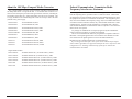
April 2006
LHC001A-R4 - LHC002A-R4
LHC005A-R4 - LHC006A-R4
LHC007A-MT-R3 - LHC008A-R3
LHC009A-R3 - LHC5129A-R3
LHC5130A-R3 - LHC5132A-R3
LHC5133A-R3 - LHC5134A
LHC5135A - LHC037A
LHC038A - LHC039A
100 Mbps
Compact Media Converter
© Copyright 2006. Black Box Corporation. All rights reserved
1000 Park Drive
*
Lawrence, PA. 35055-1018
Document Number 55-80128BB-00 A4
*
724-746-5500
*
Fax 724-746-0746
April 2006
CUSTOMER
SUPPORT
INFORMATION
Order toll-free in the U.S.: 877-877-BBOX (outside U.S. call 724-746-5500)
FREE technical support, 24 hours a day, 7 days a week: Call 724-746-5500 or fax 724-746-0746
Mail order: Black Box Corporation, 1000 Park Drive, Lawrence, PA 15055-1018
Web site: www.blackbox.com • E-mail: [email protected]
Notes:
Notes:
Table of Contents
About the 100 Mbps Compact Media Converter . . . . . . . . .1
LED Indicators . . . . . . . . . . . . . . . . . . . . . . . . . . . . . . . . . . .2
Installing the 100 Mbps Compact Media Converter . . . . . .3
Configuring the 100 Mbps Compact Media Converter . . . .4
About FiberAlert and LinkLoss . . . . . . . . . . . . . . . . . . . . . .5
Specifications . . . . . . . . . . . . . . . . . . . . . . . . . . . . . . . . . . . .7
Black Box Customer Service . . . . . . . . . . . . . . . . . . . . . . . .8
Fiber Optic Cleaning Guidelines . . . . . . . . . . . . . . . . . . . . .8
Electrostatic Discharge Precautions . . . . . . . . . . . . . . . . . . .9
Warranty . . . . . . . . . . . . . . . . . . . . . . . . . . . . . . . . . . . . . . . .9
Federal Communications Commission
Radio Frequency Interference Statement . . . . . . . . . . . . . . .10
European Directive 2002/96/EC (WEEE) requires that any
equipment that bears this symbol on product or packaging
must not be disposed of with unsorted municipal waste. This
symbol indicates that the equipment should be disposed of
separately from regular household waste. It is the consumer's
responsibility to dispose of this and all equipment so marked
through designated collection facilities appointed by government or local authorities. Following these steps through proper disposal and recycling will help prevent potential negative
consequences to the environment and human health. For
more detailed information about proper disposal, please contact local authorities, waste disposal services, or the point of
purchase for this equipment.
11
About the 100 Mbps Compact Media Converter
The Compact Media Converter converts between 100 Mbps twisted pair and
100 Mbps multi-mode or single-mode fiber. It is available with one RJ-45 connector for the twisted pair port and several types of fiber connectors, including ST,
SC and MT, for the fiber port. Single-strand fiber versions are also available. This
1U high, standalone unit includes diagnostic LEDs for each port and a universal
(100/240 VAC) power supply.
LHC001A-R4
TX/FX-MM1300-ST, 2km
LHC002A-R4
TX/FX-MM1300-SC, 2km
LHC005A-R4
TX/FX-SM1310/PLUS-ST, 40km
LHC006A-R4
TX/FX-SM1310/PLUS-SC, 40km
LHC007A-MT-R3
TX/FX-MM1300-MT, 2km
LHC008A-R3
TX/SX-MM850-ST, 300m
LHC009A-R3
TX/SX-MM850-SC, 300m
LHC037A
TX/FX-SM1310/LONG-ST, 80km
LHC038A
TX/FX-SM1310/LONG-SC, 80km
LHC039A
TX/FX-SM1550/LONG-SC, 100km
Federal Communication Commission Radio
Frequency Interference Statement
This equipment has been tested and found to comply with the limits for a
Class B computing device, pursuant to Part 15 of the FCC Rules. These limits
are designed to provide reasonable protection against harmful interference when
the equipment is operated in a commercial environment. This equipment generates, uses and can radiate radio frequency energy and, if not installed and used in
accordance with the instruction manual, may cause harmful interference to radio
communications. Operation of this equipment in a residential area is likely to
cause harmful interference in which the user will be required to correct the interference at his own expense.
Any changes or modifications not expressly approved by the manufacturer
could void the user's authority to operate the equipment.
The use of non-shielded I/O cables may not guarantee compliance with FCC
RFI limits. This digital apparatus does not exceed the Class B limits for radio
noise emission from digital apparatus set out in the Radio Interference
Regulation of the Canadian Department of Communications.
Le présent appareil numérique n’émet pas de bruits radioélectriques dépassant les limites applicables aux appareils numériques de classe B prescrites dans
le Règlement sur le brouillage radioélectrique publié par le ministère des
Communications du Canada.
Single Strand Products:
LHC5129A-R3
TX/SSFX-SM1310-SC, (1310xmt/1550rcv), 20km
LHC5130A-R3
TX/SSFX-SM1550-SC (1550xmt/1310rcv), 20km
LHC5132A-R3
TX/SSFX-SM1310/PLUS-SC (1310xmt/1550rcv), 40km
LHC5133A-R3
TX/SSFX-SM1550/PLUS-SC (1550xmt/1310rcv), 40km
LHC5134A
TX/SSFX-SM1310/LONG-SC (1310xmt/1550rcv), 60km
LHC5135A
TX/SSFX-SM1550/LONG-SC (1550xmt/1310rcv), 60km
1
10
Electrostatic Discharge Precautions
LED Indicators
Electrostatic discharge (ESD) can damage to add-in modules. Always observe
the following precautions when installing or handling an add-in module or any
board assembly.
1) Do not remove unit from its protective packaging until ready to install it.
2) Wear an ESD wrist grounding strap before handling any module or component. If without a wrist strap, maintain grounded contact with the system unit throughout any procedure requiring ESD protection.
3) Hold boards by the edges only; do not touch the electronic components or
gold connectors.
4) After removal, always place the boards on a grounded, static free surface,
ESD pad or in a proper ESD bag. Do not slide the board over any surface.
The Compact Media Converter features four diagnostic LEDs. The diagram
below shows the location of the LEDs.
Warranty
The LED functions are:
Contact Black Box for Warranty information.
FX RCV
TX LNK
FA
Glows yellow when the Converter is receiving data.
Glows green when a twisted pair link is established.
Glows green when FiberAlert is enabled and blinks when
a FiberAlert situation occurs (i.e. the loss of one strand of
fiber).
NOTE
FiberAlert does not apply and does not function on single-strand fiber versions of the 100Mbps Compact Media Converter.
FX LNK
9
Glows green when a fiber link is established.
2
Installing the 100 Mbps Compact Media Converter
While the 100 Mbps Compact Media Converter comes ready to install, all configuration changes should be made after installation. To install the Compact Media
Converter, make sure the unit is placed on a suitably flat surface. Then, attach the
cables between the Compact Media Converter and each device that will be interconnected. Finally, plug the unit into a reliable, filtered power source.
Black Box Customer Service
Order toll-free in the U.S.: Call 877-877-BBOX
(outside U.S. call 724-746-5500)
FREE technical support, 24 hours a day, 7 days a week
Call: 724-746-5500 or Fax: 724-746-0746
Mail order: Black Box Corporation
1000 Park Drive, Lawrence, PA 15055-1018
NOTE
Web site: www.blackbox.com
Since single-strand fiber products use optics that transmit and receive on
two different wavelengths, deploy single-strand fiber products in pairs,
or connect two compatible Black Box single-strand fiber products.
E-mail: [email protected]
INSTALLATION TROUBLESHOOTING
To test the 100 Mbps Compact Media Converter during installation, first test the
fiber and twisted pair connections with all troubleshooting features disabled, then
enable these features, if desired, just before final installation. This will reduce the
features’ interference with testing.
When working with units whose features cannot be disabled, both twisted pair and
fiber cables must be connected before the link LEDs will light.
To test a media converter by itself, first verify that an appropriate fiber patch cable
is being used. Then, follow these steps:
Step 1: Connect the media converter to the twisted pair device
with a twisted pair cable.
Step 2: Loop a single strand of fiber from the transmit port to
the receive port of your media converter.
Step 3: Verify that both twisted pair and fiber link LEDs light
on the Compact Media Converter.
Use the appropriate twisted pair cable, and have the crossover/pass-through switch
set correctly.
If using a high powered device designed for long distance installations in a short
distance installation, an optical attenuator may be needed to prevent data loss on a
connection.
Fiber Optic Cleaning Guidelines
Fiber optic equipment is extremely susceptible to contamination by particles of
dirt or dust which can obstruct the optics and cause performance degradation.
Good system performance requires clean optics and connector ferrules.
1) Only use fiber patch cords (or connectors) from a reputable supplier; lowquality components can cause many hard-to-diagnose problems.
2) Black Box installs dust caps to ensure factory-clean optical devices. These
protective caps should not be removed until the moment of connecting the
fiber cable to the device. Assure that the fiber is properly terminated, polished and free of any dust or dirt and that the location is as free from dust and
dirt as possible.
3) Store spare caps in a dust-free environment such as a sealed plastic bag or
box so reinstalled caps do not introduce any contamination to the optics.
WARNING
Integrated circuits and fiber optic components are extremely susceptible to
electrostatic discharge damage. Only qualified service technicians using tools
and techniques comforming to accepted industry practices should handle these
components.
4) Reinstall the protective caps when disconnecting the fiber device.
5) To clean contaminated optics, alternate between blasting with clean, dry,
compressed air and flushing with methanol to remove particles of dirt.
Contact Black Box for more information.
3
8
What Is Pulsing FiberAlert?
Pulsing FiberAlert provides the same function as FiberAlert but, rather than
ceasing transmission when the receiving unit goes down, Pulsing FiberAlert sends
pulses through the line so that once the receiving unit starts to function, transmission commences. Use Pulsing FiberAlert in the following two situations:
A) When connecting two Compact Media Converter units (or connecting a
PSE-Compact Media Converter to a 100 Mbps Module TX/FX) with
FiberAlert enabled.
B) When connecting one Compact Media Converter with FiberAlert enabled
and one 10/100 Autosensing unit with Link Fault Detection (LFD) enabled.
Converter 1
Converter 2
FiberAlert Enabled
FiberAlert and Pulsing FiberAlert Enabled
FiberAlert Enabled
FiberAlert Disabled
INSTALLATION TIP
Enable FiberAlert and/or Pulsing FiberAlert on only ONE side of a media conversion; enabling it on both sides will keep both transmitters off indefinitely.
Configuring the 100 Mbps Compact Media Converter
The 100 Mbps Compact Media Converter
features an 8-position DIP switch for configuring the unit after installation. This switch is
accessed through a cut-out in the bottom. After
configuring the DIP switch, power cycle the
Compact Media Converter for the changes to
take effect. Default settings for the following
features are shown in the diagram.
• AN ENABLED (Auto-Negotiation)
• MDI/MDI-X (Manual port setting)
• AUTO MDI/MDI-X (AutoCross)
• TX LL (TX LinkLoss)
• FX LL (FX LinkLoss)
• FA ENABLED (FiberAlert)
• FA PULSE (Pulsing FiberAlert)
Some switches are reserved for future development.
Twisted Pair Crossover/Pass-Through Connections
Whether using crossover or straight-through CAT5 twisted pair cabling, the 100
Mbps Compact Media Converter will support both types of connections by one of
the following methods:
Specifications
Environmental
Operating Temperature: 32° - 122° F (0° - 50° C)
Storage Temperature: 0° - 160° F (-20° - 70° C)
Humidity: 5 - 95% (non-condensing)
Power
AC Input Load: 100-240VAC ±10%, 50/60 Hz, 1.5A
Heat generated: 51 BTU/hr.
Dimensions
1.64”H x 4.75”W x 4.95”D (4.17 cm x 12.07 cm x 12.57 cm)
AutoCross (Switch 4): The Compact Media Converter includes AutoCross, a
feature which automatically selects between a crossover workstation or passthrough/ repeater hub connection depending on the connected device. To enable
AutoCross, move the Auto MDI/MDI-X switch to the ON position.
MDI/MDI-X (Switch 3): To manually configure the Compact Media Converter
for a pass-through (MDI) or a crossover (MDI-X) connection, set Switch 4 to OFF
and set Switch 3 to the desired connection type: MDI=OFF and MDI-X=ON. If
unsure about the type of connection, set the DIP switch to a position that makes the
twisted pair LNK (link) LED glow.
Auto-Negotiation
Auto-Negotiation, enabled by default, allows the Compact Media Converter to
communicate at the speed and duplex settings of the device to which it is connected. Therefore, if the device connected to the Compact Media Converter sends and
receives at 100Mbps, Full-Duplex, so will the Compact Media Converter. This will
function within the operating parameters of the Compact Media Converter
(10/100Mbps, Half or Full Duplex).
To make the Compact Media Converter only communicate at one speed or one
duplex setting, Auto-Negotiation will need to be turned off.
7
4
About FiberAlert and LinkLoss
The Compact Media Converter comes with the following troubleshooting features:
•
FX LinkLoss (LinkLoss over a Fiber cable)
•
TX LinkLoss (LinkLoss over a Twisted Pair cable)
•
FiberAlert (including Pulsing FiberAlert)
LinkLoss and FiberAlert are advanced troubleshooting features that can help
locate "silent failures" on a network. Users should understand how FiberAlert and
LinkLoss work, and how they will act in a network environment, before attempting to install the Compact Media Converter.
NOTE
What is FiberAlert?
FiberAlert is a troubleshooting feature that minimizes the problems associated with the loss of one strand of fiber. If a strand is unavailable, the Compact
Media Converter notes the lost link and will stop transmitting data and the link
signal until a signal or link pulse is received. The result is that the link LED
on BOTH sides of the fiber connection will go out indicating a fault somewhere
in the fiber loop. Using
FiberAlert, a local site
administrator is notified
of a fault and can quickly determine the location
of a cable fault.
Without understanding LinkLoss and FiberAlert, the 100 Mbps Compact Media
Converter could appear flawed or even malfunctioning.
Using FiberAlert and LinkLoss
About Link Integrity
During normal operation, link integrity pulses are transmitted by all point-topoint Ethernet devices. When a Compact Media Converter receives valid link pulses, it knows that the device to which it is connected is functioning, and that the copper or fiber cable coming from that device is intact. The appropriate “LINK” LED
is lit to indicate this. The Compact Media Converter also sends out link pulses
from its copper and fiber transmitters, but normally has no way of knowing
whether the cable to the other device is intact and the link pulses are reaching the
other end. FiberAlert and LinkLoss allow this information to be obtained from the
fiber, even when physical access to a remote device (and its link integrity LED) is
not available.
What Is FX LinkLoss?
The following table provides an overview of the troubleshooting features,
their functionality and the recommended settings for a pair of media converters in a typical central/main site to remote site application:
Feature
FX LinkLoss
TX LinkLoss
FiberAlert
LinkLoss/FiberAlert Comparison Table
Fault Location Disabled LEDs Enable At
Fiber
Twisted Pair
Fiber
Twisted Pair
Fiber
Fiber
Main Site Only
Remote Site Only
Remote Site Only
NOTE
FX LinkLoss is a troubleshooting feature that allows users to detect failures over
the fiber connection. When a fault occurs on the fiber segment of a conversion, FX
LinkLoss detects the fault and passes this information to the twisted pair segment.
If a Compact Media Converter is not receiving a fiber link, FX LinkLoss disables
the transmitter on the Compact Media Converter 's twisted pair port. This results
in a loss of link on the device connected to the twisted pair port.
FiberAlert is not available/applicable on single-strand fiber versions of
Compact Media Converter.
What Is TX LinkLoss?
TX LinkLoss is a troubleshooting feature that allows users to detect failures
over the twisted-pair connection. When a fault occurs on the twisted pair segment
of a conversion, TX LinkLoss detects the fault and passes this information to the
fiber segment. If a Compact Media Converter is not receiving a twisted pair link,
TX LinkLoss disables the transmitter on the media converter's fiber port. This
results in a loss of link on the device connected to the fiber port.
5
6