1
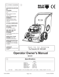
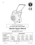
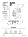
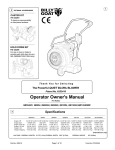
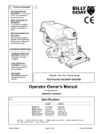
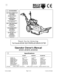
2
OPTIONAL ACCESSORIES
1
SHREDDER KIT
P/N 890209.
Shreds leaves, reducing total
volume.
ON BOARD VACUUM
HOSE KIT
P/N 890041. 4"(102mm) x
7' (2.13m)
For vacuuming in hard to
reach areas.
NOZZLE WEAR PLATES
P/N 890413.
(STD. ON KD512HCS)
Extends nozzle life when
used along curbs and hard
surfaces.
OPTIONAL DEBRIS BAGS
STANDARD TURF PRO
DEBRIS BAG
P/N 890028.
For use in leaves and grass in
non-dusty conditions.
DEBRIS BAG COVER
P/N 900801
Directs dust downward away
from operator.
ZIPPERLESS QUICK BAG
P/N 890309
Thank You for Selecting
The Powerful KD VACUUM
For non dusty conditions that
are damaging to zippers.
Operator Owner's Manual
CASTER KIT
P/N 890412
For use on hard surface
KD512, KD512HC, KD512HCS
Specifications
3
ENGINE: H.P.
ENGINE: TYPE
ENGINE: FUEL CAP
ENGINE: OIL CAP
WEIGHT: UNIT
WEIGHT: SHIPPING
WEIGHT: ENGINE
UNIT SIZE:
Part No. 890033
KD512
KD512HC
KD512HCS
5.0 (3.73 kW)
B&S QUANTUM
1.5qt. (1.4 L)
0.63qt. (0.6 L)
98# (44.5 kg)
120# (54.4kg)
24.38# (11.05 kg)
5.5 (4.11 kW)
HONDA OHC
1.16qt. (1.1 L)
0.58qt. (0.6 L)
99# (45.0 kg)
124# (56.0 kg)
22# (10.0 kg)
5.5 (4.11 kW)
HONDA OHC
1.16qt. (1.1 L)
0.58qt. (0.6 L)
116# (52.6 kg)
138# (63.0 kg)
22# (10.0 kg)
OVERALL LENGTH: 62"(1.57m) OVERALL WIDTH 26.75" (0.68m)
Page 1 of 8
OVERALL HEIGHT 42" (1.07m)
Form No. F042805A
5
IN THE INTEREST OF SAFETY
BEFORE STARTING ENGINE, READ AND UNDERSTAND THE “ENTIRE OPERATOR'S MANUAL &
ENGINE MANUAL.”
THIS SYMBOL MEANS WARNING OR CAUTION. DEATH, PERSONAL INJURY AND/OR PROPERTY
DAMAGE MAY OCCUR UNLESS INSTRUCTIONS ARE FOLLOWED CAREFULLY.
WARNING: The Engine Exhaust from this product contains chemicals known
to the State of California to cause cancer, birth defects or other reproductive harm.
WARNING: DO NOT
13. DO NOT tamper with governor springs,
governor links or other parts which may
change the governed engine speed.
1. DO NOT run engine in an enclosed area.
Exhaust gases contain carbon monoxide, an
odorless and deadly poison.
14. DO NOT tamper with the engine speed
selected by the engine manufacturer.
2. DO NOT place hands or feet near moving
or rotating parts.
15. DO NOT check for spark with spark plug
or spark plug wire removed. Use an
approved tester.
3. DO NOT store, spill or use gasoline near
an open flame, or devices such as a stove,
furnace, or water heater which use a pilot
light or devices which can create a spark.
16. DO NOT crank engine with spark plug
removed. If engine is flooded, place throttle
in “FAST” position and crank until engine
starts.
4. DO NOT refuel indoors where area is not
well ventilated. Outdoor refueling is recommended.
17. DO NOT strike flywheel with a hard
object or metal tool as this may cause
flywheel to shatter in operation. Use proper
tools to service engine.
5. DO NOT fill fuel tank while engine is
running. Allow engine to cool for 2 minutes
before refueling. Store fuel in approved
safety containers.
6. DO NOT remove fuel tank cap while
engine is running.
18. DO NOT operate engine without a
muffler. Inspect periodically and replace, if
necessary. If engine is equipped with
muffler deflector, inspect periodically and
replace, if necessary, with correct deflector.
7. DO NOT operate engine when smell of
gasoline is present or other explosive
conditions exist.
19. DO NOT operate engine with an
accumulation of grass, leaves, dirt or other
combustible material in the muffler area.
8. DO NOT operate engine if gasoline is
spilled. Move machine away from the spill
and avoid creating any ignition until the
gasoline has evaporated.
20. DO NOT use this engine on any forest
covered, brush covered, or grass covered
unimproved land unless a spark arrester is
installed on the muffler. The arrester must
be maintained in effective working order by
the operator. In the State of California the
above is required by law (Section 4442 of
the California Public Resources Code).
Other states may have similar laws. Federal
laws apply on federal lands.
9. DO NOT transport unit with fuel in tank.
10. DO NOT smoke when filling fuel tank.
11. DO NOT choke carburetor to stop
engine. Whenever possible, gradually
reduce engine speed before stopping.
12. DO NOT run engine at excessive
speeds. This may result in injury & /or
damage to unit.
6
TABLE OF CONTENTS
SAFETY INSTRUCTIONS
2
3
GENERAL SAFETY
3
ASSEMBLY
4
PARTS BAG & CONTROLS
LABELS
4
OPERATION
5-7
8-9
MAINTENANCE
PARTS DRAWING & LIST 10 - 12
TROUBLESHOOTING
12
WARRANTY PROCEDURE
○
○
○
○
○
○
○
○
○
○
○
○
○
○
○
○
○
○
○
○
○
○
○
○
○
Part No. 890033
○
○
○
○
○
○
○
○
○
○
22. DO NOT run engine without air cleaner
or air cleaner cover.
23. DO NOT operate during excessive
vibration!
24. DO NOT leave machine unattended
while in operation.
25. DO NOT park machine on a steep grade
or slope.
WARNING: DO
1. ALWAYS DO remove the wire from the
spark plug when servicing the engine or
equipment TO PREVENT ACCIDENTAL
STARTING.
2. DO keep cylinder fins and governor
parts free of grass and other debris
which can affect engine speed.
3. DO pull starter cord slowly until resistance is felt. Then pull cord rapidly to avoid
kickback and prevent hand or arm injury.
4. DO examine muffler periodically to be
sure it is functioning effectively. A worn or
leaking muffler should be repaired or
replaced as necessary.
5. DO use fresh gasoline. Stale fuel can
gum carburetor and cause leakage.
6. DO check fuel lines and fittings frequently
for cracks or leaks. Replace if necessary
7. Follow engine manufacturer operating
and maintenance instructions.
8. Inspect machine and work area before
starting unit.
SOUND
7
8
Sound tests conducted were in accordance with 2000/14/EEC
and were performed on 2/21/2002 under the conditions listed:
NOTE: Sound power level listed is the highest value for any model in this manual. Please
refer to serial plate on the unit for the sound power level for your model.
Sound level of 97 dBA at operator position
GENERAL CONDITION:
TEMPERATURE:
○
○
○
21. DO NOT touch hot muffler, cylinder, or
fins because contact may cause burns.
111 dB
(KD512 MODEL)
WIND SPEED:
WIND DIRECTION:
HUMIDITY:
Sunny
45° F (7.2° C)
5 MPH (8.1 kmh)
South West
60 %
VIBRATION
VIBRATION LEVELS 1.5g
Vibration levels at the operators handles were
measured in the vertical, lateral, and longitudinal
directions using calibrated vibration test equipment.
Tests were performed on 05/19/95 under the
conditions listed:
GENERAL CONDITION:
TEMPERATURE:
62° F (16.7° C)
WIND SPEED:
5 MPH (8.0 kmh)
WIND DIRECTION:
South
HUMIDITY:
67 %
○
BAROMETRIC PRESSURE:
OPERATOR
Page 2 of 8
30.18" Hg (767mm Hg)
Sunny
BAROMETRIC PRESSURE:
30.06" Hg (764mm Hg)
Form No. F042805A
GENERAL SAFETY
9
For your safety and the safety of others, these directions should be followed:
Do not operate this machine without first reading
owner's manual and engine manufacturer's manual.
Use of Ear Protection is recommended while
operating this machine.
Use of Eye and Breathing protection is recommended when using this machine, especially in dry
and dusty conditions. Optional bag cover directs dust
toward ground, away from the operator.
·DO NOT place hands or feet inside nozzle intake opening,
near debris outlet or near any moving parts.
·DO NOT start engine without debris bag and quick disconnect connected firmly in place to exhaust outlet.
·DO NOT start or operate machine with debris bag zipper
open.
10
ASSEMBLY
Read all safety and operating instructions
before assembling or starting this unit.
PUT OIL IN ENGINE BEFORE STARTING
Your Billy Goat is shipped from the factory in one carton,
completely assembled except for the upper handle, debris
bag, and bag quick disconnect.
11
·DO NOT operate during excessive vibration.
·DO NOT remove bag until engine has been turned off and has
come to a complete stop.
·DO NOT remove hose kit cap on nozzle until engine has been
turned off and has come to a complete stop.
·DO NOT operate machine with hose cap, bag or hose removed.
·DO NOT use this machine for vacuuming exclusively sand,
dust, fine dirt, rock, glass, string like material, grain, rags,
cans, metal, bark or water.
·DO NOT operate this machine on slopes greater than 20%.
·DO NOT pick up any hot or burning debris, or any toxic or
explosive material.
·DO NOT allow children to operate this equipment.
1. ASSEMBLE Lift upper handle (item 6), remove items 8, 30, & 32
from lower handle (item 27). Attach and secure upper handle as shown
using same hardware.
2. UNFOLD the debris bag (item 1) and fasten bag neck to bag quick
disconnect (item 64). Attach firmly to housing exhaust (item 52) see
fig. 2.
3. ATTACH bag hanger strap to bag supports (item 11),
preassembled to upper handle.
4. CONNECT spark plug wire.
PACKING CHECKLIST
These items should be
included in your carton.
If any of these parts are
missing, contact your
dealer.
Check
Check
Check
QUICK DISCONNECT
Debris Bag
890022 KD
Literature Assy
890392
Connector
Quick
Disconnect
890176
Per Model
Check
Engine
Manual Per
Model
Check
Briggs & Stratton
5.0 H.P.
Honda 5.5
GCV 160
Fig. 2
Part No. 890033
Page 3 of 8
Form No. F042805A
12
LITERATURE ASSY
P/N 890392
13
CONTROLS
KD512HC/KD512HCS MODELS
Literature Checklist
Check
Owner's
Manual
Choke Control
Owner's
Manual
890033
Fuel Shut Off
Literature
KD
Accessories
890409
Check
Literature
KD
Accessories
Throttle Control
KD512 MODEL
Check
Warranty
Card
EU Declaration
of Conformity
& EU
Distributor List
Throttle Control
Warranty
Card 400972
Choke Control
EU Declaration
of Conformity &
EU Distributor
List 890393
Check
Briggs engines have a primer
button carburetor rather than
choke type carburetor.
14
INSTRUCTION LABELS
15
These labels should be included on your Vacuum. If any of
these labels are damaged, replace them before putting this
equipment into operation. Item and part numbers are given to
help in ordering replacement labels..
Honda
WARNING
READ OWNER’S MANUAL BEFORE OPERATION.
LIRE LE MANUEL D UTILISATEUR AVANT USAGE.
VOR INBETRIEBNAHME UNBEDINGHT BEDIENUNGSANLEITUNG DURCHLESEN.
NO UTILIZAR SINANTES NO HABER LEIDO EL MANUAL
400268
EXPLOSIVE FUEL
STOP ENGINE AND ALLOW T O
COOL BEFORE REFUELING.
Label Danger
Keep Hands
and Feet
Away
Item 29 Part
No.400424
Label Do Not Fill While
Engine Is Hot
Item 63 Part No.400268
ENGINE LABELS
HONDA MOTOR CO. , L TD. MADE IN JAPAN
890254
Briggs & Stratton
Label Ear Eye Breathing
Item No. 86 Part No. 890254
Read and follow Operating
Instructions before running engine.
DANGER
Gasoline is flammable. Allow engine
to cool at least 2 minutes before fueling.
810736
Label Read Owner's
Manual Item 84
Part No.890301
Engines emit carbon monoxide,
DO NOT run in enclosed area.
Label Danger Flying Material
Item 62 Part No.810736
Read Owner’s Manual Before Operating.
Lire le manuel d’utilisation avant la mise en route.
Vor Inbetriebnahme Bedienungs - und Wartungsanleitung lesen.
Favor leer las instrucciones de operacion antes de operar el motor.
Consultare il Manuale Uso e Manutenzione prima dell utilizzo.
Las Skotselinstruktionen Innan Start.
Debris Bag
Label item 1
Part No. 890033
Page 4 of 8
Form No. F042805A
OPERATION
16
INTENDED USE: This machine is designed for vacuuming
leaves, grass clippings and other types of organic litter and
for chipping brush, limbs, corn and sunflower stalks and
palm fronds.
Debris mixed with cans, bottles and small amounts of sand
can be vacuumed; however, it is not this machine's primary
purpose. Vacuuming cans, bottles and sand will affect the
longevity of your machine.
Do not operate if excessive vibration occurs. If excessive
vibration occurs, shut engine off immediately and check for
damaged or worn impeller, loose impeller bolt, loose impeller
key, loose engine or lodged foreign objects. Note: See parts
list for proper impeller bolt torque specifications. (See trouble
shooting section on page 12).
Like all mechanical tools, reasonable care must
be used when operating machine.
Inspect machine work area and machine before operating. Make sure that all operators of this equipment are
trained in general machine use and safety.
PUT OIL IN ENGINE BEFORE STARTING.
16.1
STARTING
ENGINE: See engine manufacturer’s instructions
for type and amount of oil and gasoline used.
Engine must be level when checking and filling oil and
gasoline.
ENGINE SPEED: Controlled by throttle lever on the engine.
Under normal conditions, operate at minimum throttle to
accomplish your current cleaning task.
FUEL VALVE: Move fuel valve to "ON" position (when
provided on engine).
16.4
DEBRIS BAG
Debris bags are normal replaceable wear items.
Note: Frequently empty debris to prevent bag overloading with
more weight than you can lift.
An optional bag and dust cover is available for use where debris will be
vacuumed in dusty conditions (see Optional Accessories shown on
page 1).
DO NOT place bag on or near hot surface, such as engine. Run
engine at 1/2 throttle for first 1/2 hour to condition new bag. Your
new bag requires a break-in period to condition the pores of the
material against premature blockage. The entire bag surface
serves as a filter, and must be able to breath to have good vacuum
performance.
Be sure engine has come to a complete stop before removing
or emptying bag.
This vacuum is designed for picking up trash, organic
material and other similar debris (see Safety Warnings page 2-3).
However, many vacuums are used where dust is mixed with
trash. Your unit can intermittently vacuum in dusty areas. Dust
is the greatest cause of lost vacuum performance. However,
following these rules will help maintain your machine's ability to
vacuum in dusty conditions:
• Run machine at idle to quarter throttle.
• The debris bag must be cleaned more frequently.
A vacuum
with a clean, pillow soft bag will have good pickup performance.
One with a dirty, tight bag will have poor pickup performance. If
dirty, empty debris and vigorously shake bag free of dust.
• Pressure-wash debris bag if normal cleaning does not fully
clean bag. Bag should be thoroughly dry before use.
NOTE: Having one or more spare debris bags is a good way to reduce
down time while dirty bags are being cleaned.
DO NOT leave debris in bag while in storage.
CHOKE: Operated with throttle control (Honda only).
PRIMER: Push primer per engine instructions ( B&S only).
THROTTLE: Move remote throttle control to fast position.
Pull starting rope to start engine.
IF YOUR UNIT FAILS TO START:
See Troubleshooting on page 12.
16.2
VACUUMING OPERATION
VACUUM NOZZLE HEIGHT ADJUSTMENT: is
raised and lowered by pulling slightly upward on handle and
pulling height adjust rod (item 23) up at left rear of machine.
FOR MAXIMUM PICKUP: Adjust nozzle close to
debris, but without blocking airflow into the nozzle. NOTE: Never
bury nozzle into debris.
CLEARING A CLOGGED NOZZLE
& EXHAUST: Turn engine off and wait for impeller to
stop completely and disconnect spark plug wire.
Wearing durable gloves, remove clog. Danger, the
clog may contain sharp materials. Reconnect spark
plug wire.
16.3
HANDLING & TRANSPORTING:
Using two people to lift machine is recommended. Lift holding the
handle and front of nozzle. Secure in place during transport.
Part No. 890033
Page 5 of 8
STORAGE
16.5
Never store engine indoors or in enclosed poorly ventilated
areas with fuel in tank, where fuel fumes may reach an open
flame, spark or pilot light, as on a furnace, water heater, clothes
dryer or other gas appliance.
If engine is to be unused for 30 days or more, prepare as
follows:
Be sure engine is cool. Do not smoke. Remove all
gasoline from carburetor and fuel tank to prevent gum deposits
from forming on these parts and causing possible malfunction of
engine. Drain fuel outdoors, into an approved container, away
from open flame. Run engine until fuel tank is empty and
engine runs out of gasoline.
NOTE: Fuel stabilizer (such as Sta-Bil) is an acceptable alternative in minimizing the
formation of fuel gum deposits during storage. Add stabilizer to gasoline in fuel tank or storage
container. Always follow mix ratio found on stabilizer container. Run engine at least 10 min.
after adding stabilizer to allow it to reach the carburetor.
Do not store with debris in bag.
16.6
COMPOST
Vacuumed leaves, grass and other organic material from your own
yard can be emptied into a pile or composter to provide enriched soil
for later use as fertilizer in gardens and flower beds (see fig. 3).
NOTE:
Allow green chips to dry before spreading around living plants.
Form No. F042805A
17
PARTS DRAWING
KD512, KD512HC,
KD512HCS
Part No. 890033
Page 6 of 8
Form No. F042805A
ITEM
NO.
1
* Denotes
2
standard
3
hardware
4
item that
5
may be
purchased
6
locally.
7
8
9
10
11
12
13
14
15
16
17
18
19
20
21
22
23
24
25
26
27
28
29
30
31
32
33
34
35
36
37
38
39
40
41
42
43
44
45
46
47
48
49
50
51
52
53
18
54
55
56
57
58
59
60
61
62
63
64
65
66
Part No. 890033
PRO DEBRIS BAG (service)
KD512
Part No.
890305
1
KD512HC
KD512HCS
QTY
QTY
Part No.
Part No.
890023
1
890023
1
NUT LOCK (1/4 - 20 )
SCREW CAP ( 1/4 - 20 x 1-1/2 HEX )
HANDLE ASS’Y (incl. items 4(5),5(5),11(2),75(2),76)
AXLE HEIGHT ADJUST
SCREW HANDLE 5/16 - 18 x 1 - 3/4
CLAMP CABLE
SCREW CAP 1/4 - 20 x 1 3/4
BAR BAG SUPPORT
DOOR EXHAUST ASS’Y (incl. item 62 )
PLATE TOP ASS’Y (incl. items 29, 57, 65)
BOLT-CARRIAGE 1/4x3/4
*8160001
*8041008
900054
890389
*8041031
900407
*8041009
900039
890148
890402
*8024021
5
4
1
1
2
2
1
2
1
1
2
*8160001
*8041008
900054
890389
*8041031
900407
*8041009
900039
890148
890402
*8024021
5
4
1
1
2
2
1
2
1
1
2
*8160001
*8041008
900054
890389
*8041031
900407
*8041009
900039
890148
890402
*8024021
5
4
1
1
2
2
1
2
1
1
2
WASHER 1/4 FC ZP
*8171002
2
*8171002
2
*8171002
2
BRACKET - HEIGHT ADJUSTMENT
PLATE UPPER HEIGHT ADJUST
SPRING
TIRE - ONLY (PER ASSY)
PIN - HAIR COTTER
CABLE HEIGHT ADJUSTMENT
BOLT - CARRIAGE 5/16 - 18 x 4 1/2
890021
890005
900136
900507
900471
890019
*8024054
1
1
1
1
1
1
6
890021
890005
900136
900507
900471
890019
*8024054
1
1
1
1
1
1
6
890021
890005
900136
900507
900471
890019
*8024054
1
1
1
1
1
1
6
NUT LOCK 5/16 - 18 HEX
HANDLE LOWER KD510
PLATE HANDLE SUPPORT
LABEL DANGER CUT FINGER
WASHER FLAT CUT 5/16
*8160002
890346
900933
400424
*8171003
4
1
1
2
2
*8160002
890346
900933
400424
*8171003
4
1
1
2
2
*8160002
890346
900933
400424
*8171003
8
1
3
2
6
2
4
0 -1
*8161041
400570
900509
900997
4
2
4
0 -1
DESCRIPTION
QTY
NUT LOCK 5/16 - 18 THIN HT.
GRIP HANDLE
WHEEL ASS’Y (incl. items 21)
WASHER 0.75 “C”
900509
900997
4
0 -1
400570
900509
900997
SCREW SM 1/4x3/4 TYPE A
PLATE SKID (incl. items 54)
SPACER IMPELLER
SCREW CAP 1/4 - 20 x 1 - 1/4
*8041007
4
890616
*8041007
1
4
*8122082
890413
890616
*8041007
4
1
1
4
SCREW SELF TAPPING 10 - 24 x 1/2
NOZZLE MAINFRAME ASS’Y (incl. one of items 29,44,42)
PLUG
LINER HOLD PLATE
*8123086
890391
900146
890618
900215
1
1
1
2
1
*8123086
890391
900146
890618
890615
1
1
1
2
1
*8123086
890391
900146
890618
1
1
1
2
890615
1
900162
400502
900154
890371-S
890404
890408
890359
*8172011
2
1
1
1
1
4
15
4
900162
400502
900154
890371-S
890614
890408
890359
*8172011
2
1
1
1
1
4
15
4
900162
400502
900154
890417-S
890614
8024039
900732-S
890408
890359
*8172011
2
1
1
1
1
4
1
4
15
4
890013
890530
810736
400268
890176
890301
890254
1
4
1
1
1
1
1
890013
890530
810736
400268
890176
890301
890254
1
4
1
1
1
1
1
890013
890530
810736
400268
890176
890301
890254
1
4
1
1
1
1
1
IMPELLER ASS’Y (incl. items 49, 50, 51 )
KEY
WASHER LOCK 3/8 TWISTED TOOTH
SCREW CAP 3/8 -24 x 1 GR 8 (TORQ.50 FT-LBS)(68N.m)
HOUSING ASS’Y (incl. items 12, 14, 15, 16, 66)
ENGINE HONDA 5.5 H.P. GC160
ENGINE BRIGGS & STRATTON 5 H.P. QUANTUM IC
BOLT CARRIAGE 5/16-18x3/4"
LINE PVC
SCREW CAP 3/8 - 1-1/2 TAPTITE
SCREW CAP 1/4 - 20 x 1/2 HWH
WASHER FLAT 1/2 SAE
SCREW SOCKET HD. 5/16 - 18 x 3/4 GR. 8
HGT ADJUST ASSY (INCL. ITEMS 18, 20, 22, 23)
1/2-13 CAP NUT NP W/PATCH
LABEL DANGER FLYING MATERIAL
LABEL DO NOT FILL WHEN ENGINE IS HOT
CONNECTOR BAG QUICK
LABEL READ OWNER'S MANUAL
LABEL EAR/EYE BREATHING
Page 7 of 8
Form No. F042805A
MAINTENANCE
19
continued
19.1
Use only a qualified mechanic for
any adjustments, disassembly or
any kind of repair .
IMPELLER REMOVAL continued
7. Lift impeller upward. If impeller slides freely, proceed to (step 10).
8. Place two crowbars between impeller and housing on opposite sides. Pry impeller away
from engine until it loosens. Using a penetrating oil can help loosen a stuck impeller.
9. If the impeller does not loosen, obtain a 1” (25.4mm) longer bolt of the same diameter
and thread type as the impeller bolt. Thread longer bolt by hand into the crankshaft until
bolt bottoms. Using a suitable gear or wheel puller against the bolt head and the impeller
back-plate (near the blades), remove impeller from shaft.
10. Remove engine mounting screws, bolts, and nuts as required.
11. When impeller is free of the engine shaft, lift impeller and housing assembly off engine.
Align impeller with opening, and diagonally lift impeller out of housing.
12. Using a new impeller bolt and lockwasher, reinstall new impeller in reverse order.
13. Tighten impeller bolt. Torque impeller bolt to 50 Ft. Lbs.(68 N.m) (see item 51 on page 7).
14. Reinstall engine onto housing in reverse order of removal.
15. Gas and oil (0.69 quart).
16. Reinstall spark plug wire.
WARNING: TO AVOID PERSONAL INJURY, ALWAYS
TURN MACHINE OFF, MAKE SURE ALL MOVING
PARTS COME TO A COMPLETE STOP.
DISCONNECT SPARK PLUG WIRE
BEFORE SERVICING UNIT.
ENGINE: See engine manufacturer
operator's instructions.
19.2
DEBRIS BAG: See page 5.
Maintenance Schedule
Maintenance Operation
RECONNECT SPARK PLUG WIRE,
GUARDS, BAG, CAPS AND / OR
HOSE BEFORE STARTING ENGINE.
Follow these hourly maintenance intervals.
Every Use
Every 5 hrs.
or (Daily)
Every 25
hrs.
Engine (See Engine Manual)
Check for excessive vibration
Clean Debris Bag
19.1
IMPELLER REMOVAL
Check bag strap tightness
Inspect for loose parts
1.Wait for engine to cool and disconnect spark plug.
2.Drain fuel and oil from the engine.
3.Remove bag, quick release, and upper handle. Do not kink, stretch, or break control
cables, control housings, or end fittings while removing handles.
4. Remove housing top plate by removing bolts around outside of housing.
5. Leaving engine fastened to top plate, turn it upside down so the impeller is on
top. 6. Remove impeller bolt and lock washer.
TROUBLESHOOTING
20
Problem
Inspect for worn or damaged parts
Lubricate wheels.
Inspect wear on PVC liner (KD511HS model only)
Before Requesting Service Review These Suggestions
Possible Cause
Solution
Will not vacuum or has poor
vacuum performance.
Dirty debris bag. Nozzle height set too high or too low. Hose kit cap
missing. Clogged nozzle or exhaust. Excessive quantity of debris.
Clean debris bag. Shake bag clean or wash. Adjust nozzle height.
Check for hose kit cap. Unclog nozzle or exhaust (see page 5).
Allow air to feed with debris.
Abnormal vibration.
Loose or out of balance impeller or loose engine.
Check impeller and replace if required. Check Engine.
Engine will not start.
Stop switch off. Throttle in off position. Engine not in full choke
position. Out of gasoline. Bad or old gasoline. Spark Plug wire
disconnected. Dirty air cleaner.
Check stop switches, throttle, choke position and gasoline. Connect
spark plug wire. Clean or replace air cleaner. Or contact a qualified
service person.
Engine is locked, will not
pull over.
Debris locked in impeller. Engine problem.
See page 5, Contact an engine servicing dealer for engine
problems.
Nozzle scrapes ground in
lowest height setting.
Nozzle height out of adjustment.
Adjust nozzle height. (See Nozzle height fine adjustment for hard
surface use on page 5).
22.1
21
Engine Service and Warranty
22
Contact your nearest engine manufacturer's authorized
servicing dealer.
workmanship, the owner should make a warranty claim as follows:
Record your machine model, serial number and
date-of-purchase and where purchased
Serial Plate
-The Machine must be taken to the dealer from whom it was purchased
or to an authorized Servicing Billy Goat Dealer.
-The owner must present the remaining half of the Warranty
Registration Card, or, if this is not available, the invoice or receipt.
-The Warranty Claim will be completed by the authorized Billy Goat
Dealer and submitted to their respective Billy Goat Distributor for their
territory. Attention: Service Manager. Any parts replaced under
warranty must be tagged and retained for 90 days.
-The distributor service manager will sign off on the claim and submit
it to Billy Goat for consideration.
-The Technical Service Department at Billy Goat will study the claim
and may request parts to be returned for examination. Billy Goat will
notify their conclusions to the distributor service manager from whom
the claim was received.
-The decision by the Quality / Service department at Billy Goat to
approve or reject a Warranty claim is final and binding.
1803 S.W. Jefferson
St.
Lee's Summit, MO
64082-2312 / USA
Tel (816) 524-9666
Fax (816) 524-6983
R
Model
Serial No.
111 dB
Unit(Weight)
lbs.
Engine Power
kg
kW
rpm
min-1
Purchase
Date
Part No. 890033
WARRANTY PROCEDURE
Should a Billy Goat Machine fail due to a defect in material and / or
Note: To process a Warranty Claim, it is necessary to quote the Model & Serial
Number which are printed on the Billy Goat Serial Plate (See owner’s manual).
BILLY GOAT INDUSTRIES INC.
1803 S.W. JEFFERSON STREET LEE'S SUMMIT, MO 64082-2312 / USA
PHONE: 816-524-9666 FAX: 816-524-6983 www.billygoat.com
Purchased
from
Page 8 of 8
Form No. F042805A