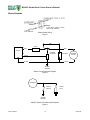
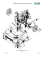
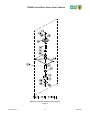
1
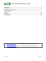
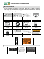
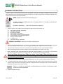
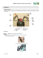
BILLY GOAT ® BC2403 Series Brush Cutter Owner’s Manual Patent Number D386768 Part No 500402 1 Form No F020513A BC2403 Series Brush Cutter Owner’s Manual CONTENTS Specifications and Sound/Vibration .................................................................................................................. 3 Instruction Labels .............................................................................................................................................. 4 Assembly Instructions ....................................................................................................................................... 5-6 Operation ........................................................................................................................................................... 7-9 Maintenance ...................................................................................................................................................... 10-19 Troubleshooting ................................................................................................................................................. 20 Illustrated Parts List ........................................................................................................................................... 21-28 Go to http://www.billygoat.com for French-Canadian translations of the product manuals. Visitez http://www.billygoat.com pour la version canadienne-française des manuels de produits Part No 500402 2 F020513A BC2403 Series Brush Cutter Owner’s Manual BC 2403 SERIES SPECIFICATIONS BC2403IC BC2403ICF BC2403HF BC2403H BC2403HEB Engine Type Briggs and Stratton INTEK OHV Briggs and Stratton INTEK OHV Honda GXV Honda GXV Honda GXV Model Number 21A902-0149-E1 21A902-0149-E1 GXV390UTIDABG GXV390UTIDABG GXV390K1DE33 Horsepower 13.0 (9.7 kW) 13.0 (9.7 kW) 13.0 (9.7 kW) 13.0 (9.7 kW) 13.0 (9.7 kW) Fuel Capacity 3.0 qt (2.80 L) 3.0 qt (2.80 L) 2.3 qt (2.18L) 2.3 qt (2.18L) 2.3 qt (2.18L) Oil Capacity 1.5 qt (1.4L) 1.5 qt (1.4L) 1.2 qt (1.13L) 1.2 qt (1.13L) 1.2 qt (1.13L) Engine Weight 58.0 lb (26.3 kg) 58.0 lb (26.3 kg) 70.5 lb (32.0 kg) 70.5 lb (32.0 kg) 72.5 lb (32.9 kg) Unit Weight 266 lb (120.7 kg) 284 lb (128.8 kg) 294 lb (133.4 kg) 278 lb (126.4 kg) 291 lb (132.3 kg) In accordance with 2000/14/EEC standards 106 dB(a) 106 dB(a) 106 dB(a) 106 dB(a) 106 dB(a) Sound at Operator’s ear 93 dB(a) 93 dB(a) 93 dB(a) 93 dB(a) 93 dB(a) Shipping Weight 315 lb (143.2 kg) 333 lb (151 kg) 348 lb (157.9 kg) 330 lb (150.0 kg) 340 lb (154.7 kg) Overall Length 82.5 in (2.09 m) Overall Width 32.0 in (0.81 m) Overall Height 43 in (1.09 m) Maximum Operating Slope 15 o 15 o 20 o 20 o 20 o SOUND DATA SOUND LEVEL 93 Dba at Operator’s position Sound tests were conducted in accordance with 2000/14/EEC and were performed on 2/21/2002 under the conditions listed below. Sound power level listed is the highest value for any model covered in this manual. Please refer to serial plate on the unit for the sound power level for your model. General Conditions: Temperature: Wind Speed: Wind Direction: Humidity: Barometric Pressure: Sunny o o 80 F (25 C) 2.0 mph (3.2 kph) South 63.5% 29.98” Hg (761mm Hg) VIBRATION DATA 2 VIBRATION LEVEL .5g (4.87 m/s ) Vibration levels at the operator’s handles were measured in the vertical, lateral and longitudinal directions using calibrated vibration test equipment. Tests were performed on 5/19/1995 under the conditions listed below. General Conditions: Temperature: Wind Speed: Wind Direction: Humidity: Barometric Pressure: Part No 500402 Sunny o o 89 F (31.7 C) 6.1 mph (9.9 kph) West 49.7% 29.88” Hg (101.19 kPa) 3 F020513A BC2403 Series Brush Cutter Owner’s Manual INSTRUCTION LABELS The labels shown below were installed on your BILLY GOAT ® Brush Cutter. If any labels are damaged or missing, replace them before operating this equipment. Item numbers from the Illustrated Parts List and part numbers are provided for convenience in ordering replacement labels. The correct position for each label may be determined by referring to the Figure and Item numbers shown. PN 400268 (Item 169) PN 890254 (Item 188) PN 500349 (Item 186) Item No 180 - PN 400424 (Item 180) Item No 184 - PN 810736 (Item 184) Item No 187 - PN 890301 (Item 187) PN 900327 (Item 185) Item No 192 - PN 500177 (Item 192) Item No 191 - PN 500176 (Item 191) Item No 189 - PN 500168 (Item 189) PN 500279 (Item 190) PN 100252 ENGINE LABELS Honda Part No 500402 Briggs and Stratton 4 F020513A BC2403 Series Brush Cutter Owner’s Manual 22 Attach shifter to linkage here 202 100 Brush Cutter Assembly Drawing Figure 1 Part No 500402 5 F020513A BC2403 Series Brush Cutter Owner’s Manual ASSEMBLY INSTRUCTIONS Your BILLY GOAT ® BC Self-Propelled Brush Cutter was shipped in one carton, completely assembled except for the upper handle assembly and the front guard bar. Mounting hardware for the handle and guard bar is temporarily installed on the lower handle and the front of the deck assembly. READ all safety instructions before assembling unit. A CB18, C50, SC50 or MCB50 series dry or wet battery with a 17.2 Ah rating is required when replacing the battery. Numbers in parenthesis ( ) refer to item numbers in the parts list. 1. Remove unit from carton. Make sure the following items that have been packed with unit: Upper Handle Assembly, P/N 500256 Guard Bar, P/N 500356 Bar Skids, P/N 500355 Owner’s Manual, P/N 500402 General Safety and Warnings Manual 100296 Honda or Briggs and Stratton Engine Manual Warranty Card, P/N 400972 Ty-Wraps (4 ea) Tube shifter with grip, P/N 500370 DISCONNECT spark plug wire before assembling unit. 2. Remove mounting hardware (143, 115, 117, and 141) from parts bag. Use this hardware to mount the upper handle (40) to the lower handle (51) and braces (5 and 6). See page 23 for bolt location. Tighten the hardware securely. 3. Tighten bolts and nuts (item 143 and 117) connecting the handle braces (5 and 6) on the transmission linkage. 4. Attach the shifter tube (item 22) with the hardware (100 and 202). Make sure the shifter moves freely. 5. Place a wood block under the deck and attach the skids (155) using the hardware (119, 141, and 117). Use the bottom two holes on the longer end to attach to the front of the deck. The bolts should run from the inside out. Warning: When attaching the Skids be careful of the blade. Wear thick gloves and check the position of the blade before putting your hands into the deck to install the bolts though the Skids. 9. Attach guard bar (31) to Skids by installing with the hardware (33, 141, and 117) into the top two holes on the skids. 10. For electric start models secure the battery in the battery plate (164), hook one side of the strap into the hole then stretch the strap across the top of the battery and hook the opposite side into the opposing hole on the plate. Make sure the battery will not move then connect terminals. Items 117, 119 and 141 secure both front skid attachment and sides of front guard bar. Make sure both are securely attached. 11. Reconnect spark plug wire. Part No 500402 6 F020513A BC2403 Series Brush Cutter Owner’s Manual OPERATION OPERATOR CONTROLS The operator’s station is at the rear of the machine between the handlebars. The operator should STAND in a position to allow both handlebars to be grasped firmly and which allows sufficient leverage to steer the machine. Operator’s controls are shown below. 4 1 5 2 6 7 3 Operator Control Locations 1 2 3 4 Blade Clutch Lever Gear Shift Lever Choke Throttle 5 6 7 ON/OFF Switch Drive Clutch Lever Pull Starter STARTING CHECK engine oil level before operating machine. 1. Place equipment on a level, firm surface that is free of rocks or other debris. 2. Place throttle in START position. Throttle 3. Pull choke out (Honda engine only). Choke Part No 500402 7 F020513A BC2403 Series Brush Cutter Owner’s Manual 4. Units equipped with electric starters: Pull up on the ON/OFF switch until engine starts. ON/OFF (I/O) (Manual start shown) DO NOT START equipment with drive or blade clutch engaged. 5. Units equipped with manual starters: Pull starter rope to start engine. PULL STARTER CORD slowly until resistance is felt. Then pull cord rapidly to avoid kickback. 6. Push choke in (Honda engine only). 7. Pull throttle control back to and allow engine to reach correct operating speed. CUTTING The best performance is achieved when cutting in dry conditions. The quality of the cut is directly related to ground speed during cutting. Under most conditions cutting should be done in first or second gear. Third gear should be reserved for conditions where weeds and brush are thinned out or not very tall. If the quality of the cut is not satisfactory, shift into a lower gear. 1. Move shift lever to correct position (1, 2, 3 or Reverse) for desired gear. Gear Shift Lever Part No 500402 8 F020513A BC2403 Series Brush Cutter Owner’s Manual 2. Press blade clutch handle down to engage blade. Allow blade to spin up to normal operating speed. Blade Clutch Lever 3. Pull drive clutch handle up to engage transaxle. Drive Clutch Lever SHUT DOWN 1. Release drive clutch handle to disengage transaxle. 2. Release blade clutch handle to disengage blade. 3. Pull throttle control all the way back to the STOP position. 4. Place the ON/OFF (I/O) switch in the OFF (O) position. CLEARING A CLOGGED CUTTING DECK DISCONNECT spark plug wire before servicing unit. 1. Shut engine off and wait for blade to stop completely. 2. Disconnect spark plug wire. 3. Remove clog from cutting deck. WEAR durable gloves. Clog may contain sharp materials. 4. Reconnect spark plug wire. Part No 500402 9 F020513A BC2403 Series Brush Cutter Owner’s Manual MAINTENANCE PERIODIC MAINTENANCE Periodic maintenance should be performed at the following intervals: Maintenance Operation Every Use Inspect for worn or damaged parts. Daily or Every 5 Hours Every 25 Hours Every 50 Hours Check for excessive vibration Inspect for loose parts. Sharpen blade. Inspect belts for wear. Lubricate throttle control cable and linkage. Check blade clutch cable tension. Inspect battery for corrosion, damage or leaks (electric start units only). Apply anti-seize compound to rear axles. Check battery strap for excessive wear or rips Every 100-150 Hours Replace blade drive and transaxle drive belts. COMMON REPLACEMENT PARTS - Blade. P/N 500210. Original equipment replacement blade. - High Lift Blade. P/N 500102. Optional replacement blade. - Traction Drive Belt. P/N 500119. Original equipment replacement drive belt. - Blade Drive Belt. P/N 500237. Original equipment replacement drive belt. - Skid. P/N 500355. Side deck skid. - Throttle Control Assembly. P/N 500213. Throttle control assembly, including cable. CLEANING Your BILLY GOAT ® Brush Cutter should be cleaned periodically to ensure optimum performance and service life. Clogs and debris should be removed from the blade area and debris should be removed from the engine cooling fins. A garden hose or pressure washer may be used for cleaning. DO NOT SPRAY WATER DIRECTLY ON THE BLADE CLUTCH WHEN USING A POWER WASHER. SEE FIGURE BELOW. Part No 500402 10 F020513A BC2403 Series Brush Cutter Owner’s Manual BLADE REMOVAL AND SHARPENING READ all safety instructions before servicing unit. Numbers in parenthesis (N) refers to the item number in Illustrated Parts List. Tools required: - 5/8” socket, 1/2” drive - Torque wrench, 1/2” drive - Jack stands or similar device adequate to support weight of machine. DISCONNECT spark plug wire before servicing unit. 1. Disconnect spark plug wire. 2. Lift and support front of unit to allow access to underside. UNIT IS HEAVY. Make sure support is adequate to support weight of machine. 3. Block blade to prevent it from rotating during removal. 4. Remove blade bolt (139), lock washer (140) and friction washer (54). Blade bolt (139) is a standard right-hand thread bolt. 5. Remove blade (50) and install replacement blade. When replacing the blade use BILLY GOAT Industries PN 500210 only. When sharpening blade make sure to sharpen all cutting edges. 6. Attach new blade with bolt (139), lock washer (140) and friction washer (54 removed earlier. Inspect fasteners for wear and replace if necessary. 7. Torque blade bolt to 55-60 ft-lbs. 8. Reconnect spark plug wire. Part No 500402 11 F020513A BC2403 Series Brush Cutter Owner’s Manual BLADE DRIVE BELT TENSION ADJUSTMENT READ all safety instructions before servicing unit. DISCONNECT spark plug wire before servicing unit. Numbers in parenthesis (N) refers to the item number in Illustrated Parts List. 1. Disconnect spark plug wire. 2. Remove two screws holding engine base door (7) and remove door. 3. Examine condition of belt and not position of idler assembly and amount of tension on belt. 4. Loosen, but do not remove, two nuts (116) on top on engine base. 5. Reset belt tension by reaching in through top of engine base with pry bar or long screwdriver and pushing idler pulley against belt to increase tension (see below). Adjusting Blade Drive Belt Tension 6. While holding belt under tension tighten two nuts (116) holding idler pulley in place. 7. Replace engine base door (7) and secure with screws removed earlier. 8. Reconnect spark plug wire. 9. Check belt tension by operating unit under conditions that caused belt slippage. If belt continues to slip it may require replacement before operation may continue. Part No 500402 12 F020513A BC2403 Series Brush Cutter Owner’s Manual BLADE CLUTCH ADJUSTMENT READ all safety instructions before servicing unit. DISCONNECT spark plug wire before servicing unit. 1. Disconnect spark plug wire. 2. As the clutch/brake wears or begins slipping or squealing, adjustment may be required to maintain proper cable tension and clutch engagement. A properly adjusted blade clutch should require 10 lbs of force to depress the end of the clutch lever. The blade clutch cable spring should stretch 1/4” to 3/8” (6.4-9.5 mm). 3. Adjust cable tension by tightening or loosening cable adjustment nut on rear of engine base (see below). Be sure to leave enough slack in cable to allow blade brake to engage. Blade Cable Adjustment If clutch continues to slip or squeal, do not operate equipment until adequate adjustment or repair has been performed. Improper adjustment can cause clutch to overheat and slip, greatly reducing performance and clutch life. 4. Reconnect spark plug wire. Part No 500402 13 F020513A BC2403 Series Brush Cutter Owner’s Manual BLADE DRIVE BELT REMOVAL AND REPLACEMENT READ all safety instructions before servicing unit. Numbers in parenthesis (N) refers to the item number in Illustrated Parts List. Tools required: - 1/2” socket, 3/8” drive - ratchet, 3/8” - drive extension, 3/8” drive - universal joint, 3/8” drive - pry bar or long screwdriver - jack stands or similar device adequate to support weight of machine. DISCONNECT spark plug wire before servicing unit. 1. Disconnect spark plug wire. 2. Lift and support rear of unit to allow access to underside. UNIT IS HEAVY. Make sure support is adequate to support weight of machine. 3. Remove two screws (103) and washers (141) holding engine base door (7) and remove door. 4. Loosen, but do not remove, two nuts (116) holding idler mounting plate (26) to relieve tension on blade drive belt (29). It may be necessary to pry idler pulley (9) away from its original position to release belt. 5. Using drive extension and universal joint, loosen, but do not remove, four screws (107) holding belt guides (149, 150) in place next to crankshaft drive pulley (9) at rear of machine. If extension and universal joint are not available, remove stop bolt (110) and nuts (116, 117) to allow idler arm to swing back and allow access to screws (107). 6. Pull transaxle drive belt (10) from groove on pulley (9). 7. Pull blade drive belt (29) from groove on pulley (9) and down past pulley. 8. Pull belt back through hole in top of engine base and remove it from machine. It will take some force to walk the belt past the front portion of the pulley. 9. Install new blade drive belt (29) on groove in pulley (9). Push remaining length of belt back through engine base toward clutch/brake drive pulley. 10. Install transaxle drive belt (10) on groove in pulley (9). 11. Reach through from rear of machine and pull new belt through and install it in the groove on the clutch/brake drive pulley. Make sure blade drive belt is properly seated in clutch/brake drive pulley (23) and is not resting in gap between clutch/brake drive pulley (23) and transaxle drive pulley (46) Part No 500402 14 F020513A BC2403 Series Brush Cutter Owner’s Manual 12. Tighten four screws (103) to secure belt guides (149, 150). Make sure belt is correctly routed. (See Figure below). 13. Adjust blade drive belt tension by reaching in through top of engine base with pry bar or long screwdriver and pushing idler pulley against belt to increase tension (see below). Adjusting Blade Drive Belt Tension 14. While holding belt under tension tighten two nuts (116) securing idler plate. 15. Check belt tension by applying force on side of belt opposite idler pulley. Belt should deflect 3/16”-1/4” (4.8-6.4 mm) with force applied perpendicular to belt. 16. Replace engine base door (7) and secure with screws (103) and washers (141). 17. Reconnect spark plug wire. FRONT LOOKING THROUGH TOP Blade Drive Belt (with Transaxle Belt not Shown) Blade Drive Belt (Between Transaxle Drive Belt and Deck) Transaxle Drive Belt Belt Routing Diagram (Top View of Machine) Figure 2 Part No 500402 15 F020513A BC2403 Series Brush Cutter Owner’s Manual TRANSAXLE DRIVE CLUTCH ADJUSTMENT READ all safety instructions before servicing unit. DISCONNECT spark plug wire before servicing unit. 1. Disconnect spark plug wire. 2. As the belt wears or begins slipping or squealing, adjustment may be required to maintain proper cable tension and clutch engagement. A properly adjusted transaxle drive clutch should require 3 lbs of force to depress the end of the clutch lever. 3. Adjust cable tension by tightening or loosening cable adjustment barrel on rear of engine base (see below). Moving the cable adjustment barrel IN decreases clutch tension. Moving the barrel OUT increases tension. DECREASE INCREASE Transaxle Cable Adjustment 4. Reconnect spark plug wire. Part No 500402 16 F020513A BC2403 Series Brush Cutter Owner’s Manual TRANSAXLE DRIVE BELT REMOVAL AND REPLACEMENT READ all safety instructions before servicing unit. Numbers in parenthesis (N) refers to the item number in Illustrated Parts List. Tools required: ½” socket and ratchet, ½” universal extension bar, pry bar or long screwdriver, adequate support for machine. - 1/2” socket, 3/8” drive - ratchet, 3/8” - drive extension, 3/8” drive - universal joint, 3/8” drive - pry bar or long screwdriver - jack stands or similar device adequate to support weight of machine. DISCONNECT spark plug wire before servicing unit. 1. Disconnect spark plug wire. 2. Lift and support rear of unit to allow access to underside. UNIT IS HEAVY. Make sure support is adequate to support weight of machine. 3. Using drive extension and universal joint, loosen, but do not remove, four screws (107) holding belt guides (149, 150) in place next to crankshaft drive pulley (9) at rear of machine. If extension and universal joint are not available, remove stop bolt (10) and nuts (116, 117) to allow idler arm to swing back and allow access to screws (107). 4. Pull belt (8-10) from groove on pulley (9) and down past pulley. 5. Slip belt (8-10) up and over pulley (9) and remove belt from machine. 6. Install new belt in grooves on pulley (46) and transaxle drive pulley (9). 7. Tighten four screws (107) to secure belt guides (149, 150). 8. Engage clutch levers and make sure belt guides do not touch belts. 9. Reconnect spark plug wire. Part No 500402 17 F020513A BC2403 Series Brush Cutter Owner’s Manual WIRING DIAGRAMS Starter Switch Wiring Figure 3 RED FUSE B RED RED 20A SWITCH STARTER SOLENOID A1 + BATTERY WHITE STARTER MOTOR - M BLACK BLACK ENGINE GROUND Starter Circuit Schematic Diagram Figure 4 MAGNETO ON/OFF SWITCH SPARK PLUG ENGINE GROUND ON/OFF Switch Circuit Schematic Diagram Figure 5 Part No 500402 18 F020513A BC2403 Series Brush Cutter Owner’s Manual TROUBLESHOOTING Problem Possible Cause Corrective Action Engine will not start. ON/OFF switch is in OFF position. Move switch to START position. Out of gasoline. Fill gas tank. Old or contaminated gasoline. Drain gas tank and fill with fresh gasoline. Spark plug wire disconnected. Connect spark plug wire. Dirty air cleaner. Clean or replace air cleaner. Starter does not turn. Battery low or dead. Charge or replace battery. (Electric start only) Battery cable disconnected or corroded. Clean and secure battery terminals. Defective starter switch or wiring harness. Replace starter switch or wiring harness. Defective starter. Replace starter. Blade drive belt tension incorrect. Adjust blade drive belt tension. Dull blade. Sharpen or replace blade. Clogged deck. Unclog deck. Excessive debris built up on or blocking blade. Clear debris from blade area. Engine RPM set too low. Check engine RPM. Blade loose or out of balance. Check blade for tightness. Rebalance if necessary. Engine loose. Check engine mounting bolts. Blade drive belt worn. Replace blade drive belt. Belt tension too low. Adjust belt tension. Belt worn or stretched. Replace belt. Pulleys worn or damaged. Replace pulleys. Clutch cable tension too low. Adjust clutch tension. Clutch worn or damaged. Replace worn or defective clutch assembly parts. Inadequate slack in clutch cable. Adjust clutch cable. Clutch worn or damaged. Replace clutch/brake assembly. Clutch lever not engaging clutch. Adjust clutch cable. Clutch cable defective. Replace cable. Belt worn or broken. Replace belt. Transaxle will not disengage. Clutch cable out of adjustment. Adjust clutch cable. Engine will not turn over. Defective blade clutch. Replace clutch. Engine problem. Contact an authorized servicing dealer for your engine. Will not cut or cutting performance is poor. Abnormal vibrations. Belt slips or smokes. Clutch slips or squeals. Blade brake will not engage. Transaxle will not engage. Part No 500402 19 F020513A BC2403 Series Brush Cutter Owner’s Manual Battery Care (For Electric-Starting Models) Proper care can extend the life of a battery. Follow these recommendations to ensure your battery’s best performance and long life: • Do not allow the battery charge to get too low. If the machine is not used, charge the battery every 4 – 6 weeks. Operate the engine for at least 45 minutes to maintain proper battery charge. • Store an unused battery in a dry area that does not freeze. • Do not charge an already charged battery. In theory, you cannot overcharge our battery with a trickle charger; however, when a battery is fully charged and the charger is still on, it generates heat that could be harmful to the battery. A fully charged battery will read 12V-13.2V with a voltmeter. • Do not continue to crank your engine when the battery charge is low. Charging the Battery Operate the engine for at least 45 minutes to maintain proper battery charge. If the battery loses its charge, you will need to use a trickle charger to recharge it. Caution: The charger should have an output of 12 volts at no more than 2 amps. Using a charger with higher amps will cause significant damage to the battery. • At 1 amp, the battery may need charging for as long as 48 hours. • At 2 amps, the battery may need charging for as long as 24 hours. NOTE: Using the Recoil Starter and then running the engine will not recharge a dead or significantly discharged battery. WHEN YOU ARE FINISHED CHARGING THE BATTERY, DISCONNECT THE CHARGER FROM THE OUTLET FIRST, THEN DISCONNECT THE BATTERY CHARGER WIRES FROM THE BATTERY. IF YOU LEAVE THE BATTERY CHARGER WIRES CONNECTED TO THE BATTERY, THE BATTERY WILL DISCHARGE ITSELF BACK INTO THE CHARGER. Part No 500402 20 F020513A BC2403 Series Brush Cutter Owner’s Manual ILLUSTRATED PARTS LIST Engine and Engine Base Assembly Figure 6 Part No 500402 21 F020513A BC2403 Series Brush Cutter Owner’s Manual ITEM NO DESCRIPTION BC2403HEB BC2403H BC2403IC Part No QTY Part No QTY Part No QTY 4 Base Assembly with labels 500240 1 500240 1 500240 1 7 Door Base Engine 500233 1 500233 1 500233 1 22 Tube Shift With Grip 500404 1 500404 1 500404 1 23 Clutch Brake 500338 1 500338 1 500338 1 24 Grip 3/4 ID - Black 610102 1 610102 1 610102 1 26 Plate Mount Idler WA 500228 1 500228 1 500228 1 27 Pulley Idler 4.5" OD X 3/8” 500270 1 500270 1 500270 1 32 Bushing Shifter 500130 1 500130 1 500130 1 45 13 HP Honda GXV390 Electric Start 500333 1 - - - - 45 13 HP Honda GXV390 - - 500334 1 - - 45 13 HP OHV B & S - - - - 520046 1 46 Pulley Drive Traction BC 500238 1 500238 1 500238 1 47 Spacer Engine WA 2401 500262 1 500262 1 500262 1 100 Screw cap ¼-20 x 1 1/4 8041007 1 8041007 1 8041007 1 104 Washer Split Lock 5/16” *8177011 2 *8177011 2 *8177011 2 105 Plate Impeller Washer 850443 1 850443 1 850443 1 106 Screw Cap 7/16-20 X 2 3/4" 440285 1 440285 1 440285 1 107 Screw cap 5/16” – 18 x 1” HCS ZP 8041028 6 8041028 6 8041028 6 113 Nut Lock 3/8-16 *8160003 1 *8160003 1 *8160003 1 116 Nut Jam 5/16-18 *8142002 2 *8142002 2 *8142002 2 117 Nut Lock 5/16-18 *8160002 8 *8160002 8 *8160002 10 118 Bolt Carriage 5/16-18 x 1” *8024040 2 *8024040 2 *8024040 2 120 Washer 3/8 FC *8171004 1 *8171004 1 *8171004 1 131 Spacer Engine 830113 1 830113 1 830113 1 141 Washer 5/16” FC *8171003 8 *8171003 8 *8171003 8 143 Screw Cap 5/16-18 x 1-3/4” *8041031 1 *8041031 2 *8041031 4 149 Guide Belt LH 500230 1 500230 1 500230 1 150 Guide Belt RH 500231 1 500231 1 500231 1 151 Screw Cap 5/16-24 x 1” *400164 2 *400164 2 - - 156 Washer lock 7/16" ST Med 8177013 1 8177013 1 8177013 1 162 Cable Battery Red W/Charge 500304 1 - - - - 163 Cable Battery Black 10" 790133 1 - - - 164 Bracket Battery Rear 500347 1 - - - - 165 Strap Hold Down 790303 1 - - - - 166 Washer 1/4” SAE 8172007 2 8172007 2 8172007 2 169 Label Fuel EN/SP - - - - 100261 1 185 900327 2 900327 2 900327 2 520200 1 - - - - 187 Label Guards Battery 12v w/ Label and hardware (Hardware can be found at hardware store) Label Read 890301 1 890301 1 890301 1 188 Label Ear Eye Breathe 890254 1 890254 1 890254 1 189 Label Chock Wheels 500168 1 500168 1 500168 1 190 Label Patent No 500279 1 500279 1 500279 1 193 194 195 196 198 199 Plate Choke Mount BC Screw Machine 10-32 x 3/4" Control Cable Choke BC Ring Retaining External 3/4” Label Outback BC Label Product Decal 500325 430248 500326 520176 500293 890456 1 1 1 1 2 1 520176 500293 890456 1 2 1 520176 500293 890456 1 2 1 200 202 205 206 210 212 Screwcap 5/16 –18 x 2 Nut lock ¼-20 2 way Label Spark Arrester Carriage bolt 5/16”-18 x ¾” ZP Label Made in U.S.A Screwcap 5/16”-18 x 3/4” 8041032 8142004 100252 8024039 520116 8041026 1 1 1 4 1 5 100252 8024039 520116 8041026 1 4 1 5 100252 8024039 520116 8041026 1 4 1 5 186 Part No 500402 22 F020513A BC2403 Series Brush Cutter Owner’s Manual Handlebar Assembly Figure 7 Part No 500402 23 F020513A BC2403 Series Brush Cutter Owner’s Manual ITEM NO DESCRIPTION 5 BC2403HEB BC2403H BC2403IC Part No QTY Part No QTY Part No QTY Handle Brace Left 500196 1 500196 1 500196 1 6 Handle Brace Right 500200 1 500200 1 500200 1 17 Cable Clutch Blade BC2402 500259 1 500259 1 500259 1 18 Cable Clutch Drive BC2402 500327 1 500327 1 500327 1 39 Lever Control Blade 500312 1 500312 1 500312 1 40 Handle Upper BC2403 500383 1 500383 1 500383 1 41 Grip Handle 1” ID x 7.5” 500267 2 500267 2 500267 2 42 Lever Control Clutch 500406 1 500406 1 500406 1 44 Cable Throttle Control 36.0” 440178 1 440178 1 440178 1 48 Control Throttle 440013 1 440013 1 440013 1 51 Handle Lower RH BC2402 500141 1 500141 1 500141 1 52 Handle Lower LH BC2402 500140 1 500140 1 500140 1 55 Guard Hand BC2402 500339 2 500339 2 500339 2 56 Throttle Plate BC2403 500385 1 500385 1 500385 1 100 Screw cap ¼-20 x 1 1/4 8041007 1 8041007 1 8041007 1 102 Nut Lock 1/4-20 *8160001 4 *8160001 4 *8160001 4 108 Screw Cap 5/16-18 x 2-3/4” *8041035 2 *8041035 2 *8041035 2 115 Screw Cap 5/16-18 x 2" *8041032 2 *8041032 2 *8041032 2 117 Nut Lock 5/16-18 *8160002 10 *8160002 10 *8160002 10 119 Screw Cap 5/16-18 x 1-1/2” *8041030 4 *8041030 4 *8041030 4 124 Washer 1/4” FC *8171002 1 *8171002 1 *8171002 1 137 Ty Wrap 900407 2 900407 2 900407 2 141 Washer 5/16” FC *8171003 9 *8171003 9 *8171003 9 142 Bracket Clutch Cable Guard 500321 1 500321 1 500321 1 143 Screw Cap 5/16-18 x 1-3/4” *8041031 6 *8041031 6 *8041031 6 144 Screw Mach Flat HD Phil #10-24 830514 2 830514 2 830514 2 145 Nut Lock LT #10-24 8164005 2 8164005 2 8164005 2 146A Grip Lever Yellow 500378 1 500378 1 500378 1 146B Grip Lever Orange 500379 1 500379 1 500379 1 147 Label Start/Stop Toggle 500329 1 - - - - 154 Screw Cap 1/4-20 x 1 3/4” 8041009 1 8041009 1 8041009 1 157 Switch box BC2403 500384 1 - - - - 158 Switch Toggle, ON/OFF 500307 1 - - - - 159 Harness Assy 500306 1 - - - - 160 Bushing Strain Relief 500282 1 - - - - 161 Label Throttle Pull Start BC 501314 1 501314 1 501314 1 170 Bolt Shoulder 3/8-16 x 1-1/2” 501313 2 501313 2 501313 2 186 Label Shift BC2402 500349 1 500349 1 500349 1 191 Label Clutch Drive 500176 1 500176 1 500176 1 192 Label Clutch Blade 500177 1 500177 1 500177 1 Part No 500402 24 F020513A BC2403 Series Brush Cutter Owner’s Manual Transaxle and Blade Deck Assembly Figure 8 Part No 500402 25 F020513A BC2403 Series Brush Cutter Owner’s Manual ITEM NO 1 3 8 9 10 11 12 13 14 16 19 20 21 29 30 31 33 34 35 36 37 38 49 50 53 54 101 102 103 104 108 109 110 111 112 113 114 115 116 117 119 122 123 124 125 126 128 130 132 133 135 136 138 139 140 141 155 156 180 184 197 200 201 211 212 DESCRIPTION Deck Assembly with Labels Deflector Front BC2402 Transaxle 3 SPD BC2402 Pulley 5.0" OD ‘A’ Section Belt Traction Drive Plate Pivot Idler/Shifter Shifter Pivot WA Pulley Idler Wheel & Tire 16" SP LH Wheel & Tire 16” SP LH Xtrac No flat BC2403HF and ICF only Arm Idler WA Bar Shift T-axle Angle Support T-axle Rod Link Shifter Belt Blade Drive Spacer Spindle BC2402 Bar Guard BC2403 Screw Cap 5/16-18 x 1 ¾” Spindle WA BC2402 Bearing 7/8" ID Sealed Press Shaft Drive Blade Spacer Spindle Bearing Pulley 7" OD x 7/8" Bore Nut Lock 3/8-16 Thin Blade 24" BC2402 Adapter Blade WA Washer Friction Blade Bolt Carriage 1/4-20 x 3/4” Nut Lock 1/4-20 Screw Cap 5/16-18 x 1-1/4” Washer Split Lock 5/16” Screw Cap 5/16-18 x 2-3/4 “ Bolt Carriage 5/16-18 x 3/4 “ Washer Flat 1/2” Pin Cotter 3/32 x 3/4" Bolt Shoulder 1/2 x 1” Nut Lock 3/8-16 Bolt Idler Screwcap 5/16"-18 x 2" HCS ZP Nut Jam 5/16-18 Nut Lock 5/16-18 Screw Cap 5/16-18 x 1-1/2” Screw Cap 1/4-28 x 1/2” GR5 Washer lock 1/4” S/T Med Washer 1/4” FC Screw Self Tap 5/16” Pin Hair Cotter Pin Cotter 3/32 x 3/4” Washer 0.765 x 1.250 x 0.060” Ring Snap 0.750” Key 3/16 x 2-1/8” Screw Cap 7/16-20 x 1-1/4” GR8 Washer 7/8 SAE Key Sq 3/16 x 5/8” Screw Cap 7/16-20 x 2” GR8 Washer Lock 7/16” Washer 5/16 FC Bar Skid BC2403 Washer lock 7/16 S/T Med Label OPEI Label Flying Debris Washer Lock 5/16 twisted tooth Washer Lock 5/16 twisted tooth heavy Snap ring Blade kit Screwcap 5/16”-18 x 3/4” Part No 500402 BC2403HEB Part No QTY BC2403H Part No QTY BC2403IC Part No QTY 500407 500125 500365 830180 500119 500122 500368 800260 500366 500170 500121 500127 500144 500237 500232 500356 8041031 500174 500101 500107 500115 500253 8161042 500210 500191 500108 8024021 *8160001 *8041029 *8177011 *8041035 8024039 900230 *8197016 500114 *8160003 800888 8041032 *8142002 *8160002 *8041030 850408 8177010 *8171002 *8123128 900471 8197016 850238 850230 9201087 800554 350153 9201072 500188 850132 *8171003 500355 8177013 400424 810736 800177 430298 850233 500210-S 8041026 500407 500125 500365 830180 500119 500122 500368 800260 500366 500371 500170 500121 500127 500144 500237 500232 500356 8041031 500174 500101 500107 500115 500253 8161042 500210 500191 500108 8024021 *8160001 *8041029 *8177011 *8041035 8024039 900230 *8197016 500114 *816003 800888 8041032 *8142002 *8160002 *8041030 850408 8177010 *8171002 *8123128 900471 8197016 850238 850230 9201087 800554 350153 9201072 500188 850132 *8171003 500355 8177013 400424 810736 800177 430298 850233 500210-S 8041026 500407 500125 500365 830180 500119 500122 500368 800260 500366 500371 500170 500121 500127 500144 500237 500232 500356 8041031 500174 500101 500107 500115 500253 8161042 500210 500191 500108 8024021 *8160001 *8041029 *8177011 *8041035 8024039 900230 *8197016 500114 *8160003 800888 8041032 *8142002 *8160002 *8041030 850408 8177010 *8171002 *8123128 900471 8197016 850238 850230 9201087 800554 350153 9201072 500188 850132 *8171003 500355 8177013 400424 810736 800177 430298 850233 500210-S 8041026 26 1 1 1 1 1 1 1 1 1 1 1 1 1 1 1 1 4 1 2 1 1 1 1 1 1 1 5 5 6 5 4 2 1 1 1 1 1 1 1 15 6 1 1 1 1 2 1 2 2 2 1 1 2 1 1 22 2 1 2 1 2 4 1 1 1 1 1 1 1 1 1 1 1 1 1 1 1 1 1 1 1 1 4 1 2 1 1 1 1 1 1 1 5 5 6 5 4 2 1 1 1 1 1 1 1 15 6 1 1 1 1 2 1 2 2 2 1 1 2 1 1 22 2 1 2 1 2 4 1 1 1 1 1 1 1 1 1 1 1 1 1 1 1 1 1 1 1 1 4 1 2 1 1 1 1 1 1 1 5 5 6 5 4 2 1 1 1 1 1 1 1 15 6 1 1 1 1 2 1 2 2 2 1 1 2 1 1 22 2 1 2 1 2 4 1 1 1 F020513A BC2403 Series Brush Cutter Owner’s Manual Blade Drive Spindle Assembly Detail Drawing Figure 9 Part No 500402 27 F020513A BC2403 Series Brush Cutter Owner’s Manual ITEM NO DESCRIPTION BC2403HEB Part No QTY BC2403H Part No QTY BC2403IC Part No QTY 134 Spindle Assembly Complete 500242 1 500242 1 500242 1 30 Spacer Spindle BC2402 500232 1 500232 1 500232 1 34 Spindle WA BC2402 500174 1 500174 1 500174 1 35 Bearing 7/8" ID Sealed Press 500101 2 500101 2 500101 2 36 Shaft Drive Blade 500107 1 500107 1 500107 1 37 Spacer Spindle Bearing 500115 1 500115 1 500115 1 38 Pulley 7" OD x 7/8" Bore 500253 1 500253 1 500253 1 53 Adapter Blade WA 500191 1 500191 1 500191 1 54 Washer Friction Blade 500108 1 500108 1 500108 1 135 Screw Cap 7/16-20 x 1-1/4” GR8 800554 1 800554 1 800554 1 136 Washer 7/8 SAE 350153 1 350153 1 350153 1 138 Key Sq 3/16 x 5/8” 9201072 2 9201072 2 9201072 2 139 Screw Cap 7/16-20 x 2” GR8 500188 1 500188 1 500188 1 140 Washer Lock 7/16” 850132 1 850132 1 850132 1 156 Washer lock 7/16 S/T Med 8177013 1 8177013 1 8177013 1 Part No 500402 28 F020513A