1
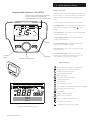
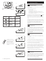
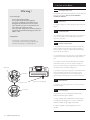
User’s Operating Instructions &
Important Warranty Information
Ecogen 24/1.0
Gas Fired Wall Mounted Condensing Boiler
and Power Generator
Please keep these instructions in a safe place.
If you move house, please hand them over to the next occupier.
© Baxi Heating UK Ltd 2010
Contents
Section
Natural Gas
Page
1.0
Quick Reference Guide
3
2.0
Introduction
4
3.0
The Programmers
5
4.0
Setting the Time
6
5.0
Setting the Central Heating Times
7
6.0
Setting the DHW Times
9
7.0
Mode Selection/Temp Adjustment
11
8.0
Contents of Other Functions
14
9.0
Resetting the Boiler
16
10.0
Clearance
17
11.0
Error Codes
18
The default time for this action is monday 8am every week.
12.0
Care of the boiler
20
If the set point has been reduced to say 40° C for safety reasons, the users must
13.0
Legislation
21
14.0
Notes
22
Baxi Ecogen 24
G.C.No 41 075 60
This appliance contains a small scale embedded generator (SSEG).
Both the District Network Operator and the Electricity Provider
must be informed, this is a legal requirement - see section 12.3.
This appliance contains a pressure vessel filled with Helium to 23 bar.
Do not strike, drop, drill or puncture the vessel.
Do not unbolt any of the covers or flanges.
The vessel contains no user serviceable parts.
Dispose of safely.
Legionella
If the DHW cylinder has been fitted with a control sensor instead of a thermostat
for increased efficiency, the control will recognise this and automatically initiate an
anti-legionella function. In this case the user should be aware that once a week the
DHW set point is overridden and the cylinder is heated to 65° C for 10 minutes.
bear in mind that the temperature around this time may be much hotter than usual.
The time of the function may be altered or the action disabled.
The Benchmark Scheme
Baxi Heating UK Ltd is a licensed member of the Benchmark Scheme which aims
to improve the standards of installation and commissioning of domestic heating
and hot water systems in the UK and to encourage regular servicing to optimise
safety, efficiency and performance.
Benchmark is managed and promoted by the Heating and Hotwater Industry
Council. For more information visit www.centralheating.co.uk
© Baxi Heating UK Ltd 2010 All rights reserved. No part of this publication may
be reproduced or transmitted in any form or by any means, or stored in any
retrieval system of any nature (including in any database), in each case whether
electronic, mechanical, recording or otherwise, without the prior written
permission of the copyright owner, except for permitted fair dealing under
Copyrights, Designs and Patents Act 1988.
Applications for the copyright owner’s permission to reproduce or make other
use of any part of this publication should be made, giving details of the proposed
use, to the following address:
The Company Secretary, Baxi Heating UK Ltd, The Wyvern Business Park,
Stanier Way, Derby, DE21 6BF.
Full acknowledgement of author and source must be given.
WARNING: Any person who does any unauthorised act in relation to a
copyright work may be liable to criminal prosecution and civil claims for damages.
0086
2
© Baxi Heating UK Ltd 2010
Boiler Controls - see opposite page
for Operating Quick Reference Guide
1.0 Quick Reference Guide
The Easy menu button
Programmable Operator Unit (POU)
24 hour time bar for central heating and domestic
hot water - shows active programme times
- Default 6am - 9am, 11am - 12pm & 15pm - 22pm
Commonly required functions are available more quickly via the
easy menu button. To access, press the easy menu button and
scroll through confirm your selection by pressing the dial
button.
Commonly required functions are shown in order below: 1. Standby/operation - the on/off switch - in the off mode frost
protection for the appliance is active: displays
when in
standby.
04. November
Tuesday
2008
2. Hot water boost - The domestic hot water is heated to the
required temperature once.
08:50
3. Central heating mode CH1 - easy access to change the
operating mode see Section 7.1
Standby
4. Room temperature CH1 - The central heating setpoint
temperature can be altered permanently.
5. Hot water mode - easy access to change the operating
mode see Section 7.4
Easy Menu
Button
Menu Button
6. Hot water temp setpoint - The hot water setpoint
temperature can be altered permanently as long as a tank
sensor is fitted. If no sensor is fitted --- appears.
Dial Knob (Turn /Push Select)
Display Descriptions
Burner in Operation 1 - Engine 2 - Supplementary
Heating to the Room temperature Set Point
Heating to the Reduced Set Point
Central Heating Times Active
DHW Time Active
Combustion Check Function Active
Holiday Function Active
Manual Overide
Time Switch Function Active
Communication between POU & PCB Control Established
POU Programmed as Room Unit
Error Message
Standby - Appliance ON/OFF
Text 1
Text 2
Text 3
Outdoor Sensor Connected
System / Appliance Attention Required
Maintenance / Special Mode
Change Battery (only if radio control fitted)
Display showing all available segments
© Baxi Heating UK Ltd 2010
3
2.0 Introduction
2.1
Description
1. The appliance incorporates a Stirling engine which is capable of
generating between 0.4 – 1.0 kW of electrical power depending on
the running conditions of the heating system. High return
temperatures especially above 65°C will reduce the power generation.
It is therefore in the interests of the householder to ensure that the
central heating system is maintained and working as efficiently as
possible. Balance the radiators in the central heating system so that
there is suitable drop in temperature across each radiator. 20°C is
optimum for new systems but some older radiators originally installed
with non condensing appliances may only manage 11°C.
2. The use of a programmable room unit incorporating a room
sensors (as apposed to a room thermostat) will also improve the
power generation.
3. If the return temperature to the appliance gets too hot the engine
burner will switch off to protect the engine – in this case the
supplementary burner will light on its own until the return
temperature has cooled sufficiently and the engine burner will be
enabled again.
4. The electricity generated in this manner if not consumed directly by
the user is fed back into the grid. Arrangements can be made with the
electricity provider to compensate the householder by way of a feedin tariff. See section 13.3.
5. It is your responsibility to contact your electricity supplier and
inform them that you have installed a Baxi Ecogen which will generate
electricity. This is a legal requirement.
6. Operation and control is similar to a domestic boiler and is fully
automatic.
7. All interactions with the appliance are either through the removable
Programmable Operator Unit (POU) on the front of the appliance or
on a remote wall cradle.
2.2
Important Notes
1. Read and follow these instructions thoroughly before switching on
and operating this appliance. These instructions must be followed and
warning labels must be adhered to.
POU
2. As with any domestic boiler, flammable materials MUST NOT be
placed near this appliance and materials emitting flammable vapours
must not be stored in the same room.
Do not position a kettle or toaster directly below the appliance.
3. The appliance MUST NOT be tampered with, abused or any sealed
components adjusted as this may result in a hazardous situation.
4. Please note that because of the high efficiency of the appliance,
condensate (water) is produced from the flue gases. A condensate
‘plume’ (water vapour) may also be seen coming out of the flue.
Gas Connection
5. Your Baxi Ecogen appliance has been installed by a Gas Safe
registered installer– this is both good safe working practice and
complies with the current gas safety regulations.
Electrical Connection
6. Your Baxi Ecogen appliance has been installed in accordance with
the Installation Instructions, this means that:
The appliance has been earthed.
The electricity supply to the appliance is 230V ~ 50Hz.
Wall Cradle (Accessory)
POU
7. Connection to the electricity supply has been made in a way that
allows complete isolation of the electricity supply from the appliance.
The isolation switch is located in an accessible position within your
installation.
8. It is a legal requirement that both the District Network Operator
(DNO) and the electricity provider are informed of the installation of
this appliance - see section 13.3.
NOTE: In the event of a power failure the appliance will turn off
automatically and will not restart for at least 3 minutes after the
power supply has been restored.
4
© Baxi Heating UK Ltd 2010
3.0 The Programmers
3.1
Getting Started
1. Ensure that both gas and electricity are turned on to the
appliance.
2. The Gas Safe registered installer will have set-up the appliance to
a programme of your choice and it should be providing heat and
hot water in line with your requirements. These can be altered via
the wall-mounted room unit or the programmer on the product
fascia, both of which are shown in this section. Section 4.0 and 5.0
detail how the timings and settings for your heating and hot water
can be changed.
3.2
Programmable Operator Unit (POU)
1. This is located at the base of the appliance on the front cover. It
displays important information about how the appliance is working
and allows you to alter settings to configure the operation to your
requirements.
2. It can be removed from the appliance to act as a programmable
room unit (PRU) when mounted in a wall cradle accessory. This
then becomes a temperature sensor and programmer.
3. If your Ecogen appliance has been installed using the existing
room temperature and time controls the installer should have
made sure that the appliance programs for the central heating and
domestic hot water are set to 24hr operation – see sections 7.1
and 7.3 - choose ‘On’ in both cases.
4. Refer to the instructions for the existing programmers for setting
the timed periods and the room temperatures. The programmable
operating unit will display the boiler flow temperature and any
errors see section 9 onwards.
3.3
POU
POU as a Programmable Room Unit (PRU)
1. The Room Unit Wall Cradle accessory is available in two
formats.
a) Hard Wired i.e fixed to a wall, the screen illuminates upon
operation.
b) Radio Frequency, cradle mounted and portable, with no
permanent screen illumination.
2. The Radio Frequency unit is powered by three AA batteries
located in the rear of the unit behind a slide down panel. If battery
power is depleted a warning symbols appears on the display
screen, replace the batteries.
3. The operation of both Radio Frequency and hard wired units is
identical.
3.4
5 LED Unit
1. The 5 LED Unit is fitted when the POU is removed and gives
basic information about the state of the appliance:Wall Cradle (Accessory)
Reset Button
5 LED Unit
© Baxi Heating UK Ltd 2010
1st Green
2nd Green
1st Yellow
2nd Yellow
Red
-
Mains On
Communication Status
Engine Burner On
Supplementary Burner On
Fault Present
2. The Reset Button may be used to reset User Errors - see
Section 11.0.
5
4.0 Setting the Time
04. November
Tuesday
2008
08:50
4.1
The time, day, date and year can be adjusted using the
POU/PRU as shown below.
Menu Button
Dial Knob
Display Screen
STEP 1
The basic display is shown.
If the basic display is not
showing, press the MENU
button.
until the
basic display is shown
Time Setting
STEP 2
Press the MENU button.
04. November
Tuesday
2008
--------------------------------------------------Information
Set time and date
08:50
STEP 3
STEP 4
Turn the Dial Knob clockwise
to highlight ‘Set Time and
Date’.
Press the Dial Knob to
select .
Information
Set time and date
Operator section
Set time and date
Hours / minutes
09:07
STEP 3
STEP 5
STEP 6
Press the Dial Knob and the
hour number flashes. Turn
Dial to the required hour.
Press the Dial Knob and the
minute number flashes. Turn
Dial to the required minute.
Press the Dial Knob.
Set time and date
Hours / minutes
Set time and date
11:07
Hours / minutes
STEP 7
Turn the Dial Knob clockwise
until Day / month is shown.
Press the Dial Knob and the
month number flashes. Turn
Dial to the required month.
11:30
STEP 8
Press the Dial Knob and the
day number flashes. Turn Dial
to the required day. Press the
Dial Knob.
Set time and date
Day / month
Set time and date
05:06
Day / month
STEP 9
Turn the Dial Knob clockwise
until Year is shown. Press the
Dial Knob and the year
number flashes. Turn Dial to
the required year.
03:06
STEP 10
Press the Dial Knob. Time
setting is now complete.
Set time and date
Year
Set time and date
2008
Year
2009
STEP 11
Press the MENU button
twice to return to normal
display screen.
03. June 2009
Wednesday
6
© Baxi Heating UK Ltd 2010
11:30
5.0 Setting the Central Heating Times
04. November
Tuesday
2008
08:50
5.1
Programming the Central Heating Times
The programmar enables control of up to three periods a day,
seven days a week.
Menu Button
Dial Knob
Display Screen
There are 3 time programs preinstalled to aid reprogramming:Time program 1 is the default with 3 time periods - Mon-Sun,
6-9, 11-12 and 15-22.
Time program 2 has two time switch periods - Mon-Sun, 6-9
and 15-22.
Time program 3 has one time switch period 6-22.
‘Preselection’ regimes are: Mon-Sun (Default) Mon-Fri and Sat-Sun
or each day individually.
If there are two heating circuits with two PRU’s each room/floor
must be programmed using the respective PRU. Choose the
relevant heating circuit at STEP 3.
When programming individual days, the opportunity to copy one
day to another is offered (screen 529). Lastly screen 536 enables a
reset to the default values as given above.
STEP 1
The basic display is shown.
If the basic display is not
showing, press the MENU
button.
until the
basic display is shown
STEP 2
Press the MENU button.
04. November
Tuesday
2008
--------------------------------------------------Information
Set time and date
08:50
STEP 3
STEP 4
Turn the Dial Knob clockwise to
highlight ‘Time central heating
CH1’.
Press the Dial Knob to
select .
Operator section
Time central heating CH1
Time hot water
Press the Dial Knob and the
day / days regime flashes.
Turn Dial to the required day
or days Mon-Sun, Mon-Fri,
Sat-Sun
Mon, Tue, Wed,
Thu, Fri, Sat, Sun
Press Dial to
select.
Time central heating CH1
Select days
Mon - Sun
STEP 5
STEP 6
Turn the Dial Knob one click
clockwise.
Time cental heating CH1
Select days
Mon - Sun
Time central heating CH1
Mon - Sun
Select default timings?
STEP 7
Press the Dial Knob and the
time program regime flashes.
Turn Dial to the ‘Time setting
1’. Press Dial to select and the
screen goes back to STEP 6.
STEP 8
Turn the Dial Knob one click
clockwise.
Time central heating CH1
Mon - Sun
Time setting 1
Set to
© Baxi Heating UK Ltd 2010
Time central heating CH1
Mon - Sun: 1st Time ON
06:00
7
5.0 Setting the Central Heating Times
04. November
Tuesday
2008
08:50
5.1
Programming the Central Heating Times (cont)
Menu Button
Easy Menu
Button
Dial Knob
Display Screen
STEP 9
Press the Dial Knob and the
‘1st Time ON’ time will flash.
Turn the Dial Knob to the
required time. Press Dial to
select.
STEP 10
Time central heating CH1
Mon - Sun: 1st Time ON
08:00
Turn the Dial Knob one click
clockwise and then press the
Dial Knob. The ‘1st Time OFF’
time will flash. Turn the Dial to
the required time. Press the
Dial to select.
STEP 11
Time central heating CH1
Mon - Sun: 1st Time OFF
10:00
STEP 12
Press the Dial Knob and the
‘2nd Time ON’ time will flash.
Turn the Dial Knob to the
required time. Press Dial to
select.
Turn the Dial Knob one click
clockwise.
Time central heating CH1
Mon - Sun: 2nd Time ON
Time central heating CH1
Mon - Sun: 2nd Time ON
11:00
11:50
If --:-- appears when adjusting the ON/OFF Time it is
because the ON is the same as OFF. If this is selected the
Time period will disappear. A new Time period can be
introduced by starting from 24.00 and winding backwards.
Turn the Dial Knob one click
clockwise and then press the
Dial Knob. The ‘2nd Time OFF’
time will flash. Turn the Dial to
the required time. Press the
Dial to select.
STEP 13
STEP 14
Turn the Dial Knob one click
clockwise.
Time central heating CH1
Mon - Sun: 2nd Time OFF
Time central heating CH1
Mon - Sun: 3rd Time ON
13:00
STEP 15
Turn the Dial Knob one click
clockwise and then press the
Dial Knob. The ‘3rd Time OFF’
time will flash. Turn the Dial to
the required time. Press the
Dial to select.
Press the Dial Knob and the
‘3rd Time ON’ time will flash.
Turn the Dial Knob to the
required time. Press Dial to
select.
Time central heating CH1
Mon - Sun: 3rd Time ON
17:00
8
© Baxi Heating UK Ltd 2010
15:00
STEP 16
Time central heating CH1
Mon - Sun: 3rd Time OFF
23:00
6.0 Setting the DHW Times
04. November
Tuesday
2008
08:50
6.1
Programming the Domestic Hot Water Times
The programmar enables control of up to three periods a day,
seven days a week.
Menu Button
Dial Knob
Display Screen
There are 3 time programs preinstalled to aid reprogramming:Time program 1 is the default with 3 time periods - Mon-Sun,
6-9, 11-12 and 15-22.
Time program 2 has two time switch periods - Mon-Sun, 6-9
and 15-22.
Time program 3 has one time switch period 6-22.
‘Preselection’ regimes are: Mon-Sun (Default) Mon-Fri and
Sat-Sun or each day individually.
If there are two heating circuits with two PRU’s each room/floor
must be programmed using the respective PRU. Choose the
relevant heating circuit at STEP 3.
When programming individual days, the opportunity to copy one
day to another is offered (screen 529). Lastly screen 536 enables
a reset to the default values as given above.
STEP 1
STEP 2
1. The basic display is shown.
If the basic display is not
showing, press the MENU
button.
Press the MENU button.
04. November
Tuesday
2008
--------------------------------------------------Information
Set time and date
08:50
STEP 3
STEP 4
Turn the Dial Knob clockwise
to highlight ‘Time hot water’.
Press the Dial Knob to
select .
Time central heating CH1
Time hot water
Holidays heating CH1
Press the Dial Knob and the
day / days regime flashes.
Turn Dial to the required day
or days Mon-Sun, Mon-Fri,
Sat-Sun,
Mon, Tue, Wed,
Thu, Fri, Sat, Sun
Press Dial to
select.
Time hot water
Select days
Mon - Sun
STEP 5
STEP 6
Turn the Dial Knob one click
clockwise.
Time hot water
Select days
Time hot water
Mon - Sun
Select default timings?
Mon - Sun
STEP 7
Press the Dial Knob and the
time program regime flashes.
Turn Dial to the ‘Time setting
1’. Press Dial to select and the
screen goes back to STEP 6.
Turn the Dial Knob one click
clockwise.
Set to
© Baxi Heating UK Ltd 2010
STEP 8
Time hot water
Mon - Sun
Time setting 1
Time hot water
Mon - Sun: 1st Time ON
06:00
9
6.0 Setting the DHW Times
04. November
Tuesday
2008
08:50
6.1
Programming the Domestic Hot Water Times (cont)
Menu Button
Easy Menu
Button
Dial Knob
Display Screen
STEP 9
Press the Dial Knob and the
‘1st Time ON’ time will flash.
Turn the Dial Knob to the
required time. Press Dial to
select.
STEP 10
Time hot water
Mon - Sun: 1st Time ON
06:30
Turn the Dial Knob one click
clockwise and then press the
Dial Knob. The ‘1st Time OFF’
time will flash. Turn the Dial
to the required time. Press the
Dial to select.
STEP 11
Time hot water
Mon - Sun: 1st Time OFF
08:30
STEP 12
Press the Dial Knob and the
‘2nd Time ON’ time will flash.
Turn the Dial Knob to the
required time. Press Dial to
select.
Turn the Dial Knob one click
clockwise.
Time hot water
Mon - Sun: 2nd Time ON
Time hot water
Mon - Sun: 2nd Time ON
11:00
11:30
If --:-- appears when adjusting the ON/OFF Time it is
because the ON is the same as OFF. If this is selected the
Time period will disappear. A new Time period can be
introduced by starting from 24.00 and winding backwards.
Turn the Dial Knob one click
clockwise and then press the
Dial Knob. The ‘2nd Time OFF’
time will flash. Turn the Dial to
the required time. Press the
Dial to select.
STEP 13
STEP 14
Turn the Dial Knob one click
clockwise.
Time hot water
Mon - Sun: 2nd Time OFF
Time hot water
Mon - Sun: 3rd Time ON
13:30
STEP 15
Turn the Dial Knob one click
clockwise and then press the
Dial Knob. The ‘3rd Time OFF’
time will flash. Turn the Dial to
the required time. Press the
Dial to select.
Press the Dial Knob and the
‘3rd Time ON’ time will flash.
Turn the Dial Knob to the
required time. Press Dial to
select.
Time hot water
Mon - Sun: 3rd Time ON
17:00
10
© Baxi Heating UK Ltd 2010
15:00
STEP 16
Time hot water
Mon - Sun: 3rd Time OFF
19:30
7.0 Mode Selection/Temp Adjustment
04. November
Tuesday
2008
08:50
7.1
Menu Button
Easy Menu
Button
Dial Knob
STEP 1
The basic display is shown.
If the basic display is not
showing, press the MENU
button.
until the
basic display is shown
04. November
Tuesday
2008
08:50
STEP 2
--------------------------------------------------Information
Set time and date
3. To select the mode required: - from the main screen press
the menu button.
4. Turn Dial to ‘Temps / mode CH1’.
STEP 3
Turn the Dial Knob clockwise to
highlight ‘Temps / mode CH1’.
Press dial to select and scroll between: - Protection – Timed –
Reduced – On, press dial to select.
Holidays heating CH1
Temps / mode CH1
Temps / mode hot water
7.2
Further Information
1. The user must be aware that in the automatic mode the
programmer is not inactive in between the programmed times,
the frost protection/reduced temperature period is constantly in
the background and will cause the appliance to come on if the
room temperature falls below the reduced temperature
setpoint (5° default) or 5°C during frost protection.
STEP 4 - For this example choose Comfort
Temps / mode CH1
Operating mode
On
STEP 5
Turn the Dial Knob until ‘Room
temperature CH1’ is displayed.
Press the Dial Knob and the °C
will flash, turn the Dial to set the
required °C and then press the
Dial Knob to select..
1. There are 4 central heating modes: On
- heating operates to keep the dwelling at
the comfort set point chosen by the
householder continuously ie. 24hr/day,
initially set at 20°C.
Timed
- heating operates to keep the dwelling at
the comfort set point chosen by the
householder according to the
programme times, initially set at 20°C
(min 10°C - max 35°C).
Reduced
- heating operates to keep the dwelling at
the reduced set point chosen by the
householder continuously, initially set at
5°C (min 5°C - max 20°C).
Protection
- heating operates to keep the dwelling
above 5°C continuously.
2. The central heating mode can be set using either the POU
on the appliance or the room unit PRU.
Press the MENU button.
Press the Dial Knob twice and
then turn the Dial Knob to the
required space heating mode i.e.
On or Timed or Reduced or
Protection. Press the Dial Knob
to select.
Selecting the Cental Heating Mode
Temps / mode CH1
Room temperature CH1
18.0 °C
NOTE: Adjustment of the room temperature during these
periods will result in a temporary change to the reduced
temperature setting until the next comfort period is
activated.
2. The central heating may be switched on at any time by
increasing the room temperature setpoint to a greater value
than the indicated room temperature whether in or out of a
programmed period. This setpoint change will remain active
until the next programmed comfort period when the setpoint
will revert to the permanent comfort setpoint.
STEP 6
The Process for setting the
Reduced setpoint is the same.
When STEP 4 is reached
choose Reduced and then
continue with STEP 5 but turn
Dial to ‘Reduced setpoint’.
© Baxi Heating UK Ltd 2010
Temps / mode CH1
Reduced setpoint
10.0 °C
11
7.0 Mode Selection/Temp Adjustment
04. November
Tuesday
2008
08:50
7.3
Menu Button
Easy Menu
Button
Dial Knob
DOMESTIC HOT WATER MODE
STEP 1 - Press the MENU button
and then
turn the Dial Knob clockwise to highlight ‘Domestic
hot water’.
Selecting the Domestic Hot Water (DHW) mode
1. There are 2 DHW modes: Off
- heating operates to keep the domestic
(Protection)
hot water cylinder above 8°C
continuously.
On
- heating operates to keep the domestic
(Timed)
hot water at the comfort set point
chosen by the householder according to
the programme times, initially set at 65°C.
2. The DHW mode can be set using either the POU on the
appliance or the PRU.
Temps / mode CH1
Temps / mode hot water
Diagnostics engine
STEP 2 - Press the Dial
Knob to select .
3. To select the mode required: - from the main screen press the
menu button, scroll down to ‘Domestic hot water’.
Temps / mode hot water
Operating mode
On
STEP 3 - Press the Dial Knob
again and the On Off mode
will flash. While flashing turn
the Dial to toggle between
On and Off. Press Dial to
select.
4. Press dial to select, select Operating mode by pressing the dial
again, scroll between : - Off and On and select by pressing the
dial.
7.4
Adjusting the Room temperature set point
1. From the main screen - turn the dial until the desired
temperature is displayed, press the dial to confirm.
2. If the temperature is being adjusted from the appliance
connected to two heating circuits, the heating circuit must be
chosen first.
ROOM TEMPERATURE SETPOINT
Temporary room setpoint
STEP 1 - Turn the Dial Knob
and the temperature will
appear. Turn the Dial Knob
again and whilst flashing keep
turning the dial to display the
required temperature.
Temporary room setpoint
Valve Confirmed
STEP 2 - Press the Dial Knob
to select.
3. Between the programmed times there is a minimum setback
or reduced temperature which is set to 5°C (see Section 7.1
STEPS 1 to 6). This may be permanently changed to set a higher
minimum temperature ie. 10°C or temporarily changed by
turning the dial knob between a programmed period and
selecting the desired temperature. This facility may be used to
heat the house outside the programmed periods.
4. The reduced temperature setting will revert to the
permanently stored value at the beginning of the next
programmed period.
7.5
Adjusting the DHW Tank Temperature
1. If the tank is fitted with a tank sensor to measure the
temperature, the setpoint temperature may be adjusted using the
POU/PRU as follows:Press the easy menu button
Turn the dial knob to highlight ‘ Hot water temp setpoint’.
Press the dial knob to select.
Turn the dial knob to change the temperature to the
desired temperature.
Press the dial knob to confirm.
The maximum setpoint temperature is 65°C
The main screen will return after a short while, otherwise press
the menu button to return immediately.
12
© Baxi Heating UK Ltd 2010
7.0 Mode Selection/Temp Adjustment
04. November
Tuesday
2008
08:50
7.6
1. Holiday - When the holiday mode is activated the
‘protection’ mode is activated for the selected period see
section 7.1
Menu Button
Easy Menu
Button
Holiday mode
Dial Knob
2. The Holiday mode is activated by using the menu button
scroll down to ‘Holiday heating CH1’, press the dial
HOLIDAY MODE
3. Press again to set the month scroll and select – (the display
will start at 01,01) set the day scroll and select. Scroll again to
‘Operating’ level, scroll between - protection and reduced select the mode required
STEP 1 - Press the MENU button.
7.7
Time hot water
Holidays heating CH1
Temps / mode CH1
Holidays heating CH1
Start
Day / month
STEP 2 - Turn the Dial Knob to highlight
‘Holidays heating CH1’ and press the Dial
to select the start period.
- -.- -
STEP 3 - Press the Dial Knob and the
Day/month starts flashing, turn the Dial to
required month and press Dial to select
and then repeat to select the day.
Holidays heating CH1
End
Day / month
- -.- -
STEP 4 - Turn the Dial Knob to highlight
‘End’ and press the Dial. The Day/month
starts flashing, turn the Dial to required
month and day as in STEP 3 to end the
holiday period.
Programme Lock
1. There is a programme lock function available to stop the
programmer being either tampered with or accidentally altered.
2. After the programme lock has been activate, only the
temporary setpoints, comfort, reduced temperature or the
functions via the easy menu such as standby/operation or HW
push are available for change by the user.
3. To activate the programme lock: a) Press the menu button to access ‘info’, then scroll and press
to choose ‘operator section’, scroll to the programme lock
option, press and scroll from ‘off’ to ‘on’. Confirm by pressing
the dial knob.
b) Accessing programme lines is now still possible but when
attempting to alter any parameters the screen will show
‘programme locked’.
4. To remove the programme lock: a) To temporarily unlock the programmer press the menu
button to access ‘info’ then press and hold the easy menu and
dial button until ‘programme temporarily unlocked’ appears.
b) In this state any alterations can be made until returning to the
standard screen when the programming lock is activated again.
c) To remove the programme lock permanently: - whilst
temporarily unlocked, access the programme lock screen as
described above, and press and scroll from ‘on’ to ‘off’. Confirm
by pressing the dial button.
© Baxi Heating UK Ltd 2010
13
8.0 Contents of Other Functions
8.1
Selecting Information
The following information is also available by pressing the menu
button and selecting ‘information’ by pressing the Dial Knob, any
error is displayed first then : 1. Room temperature – ?C (PRU only).
2. Boiler temperature – ?C.
3. State burner – 1+2 (1=engine, 2= supplementary burner on).
4. Power – Watts.
5. Energy to date – kWh.
6. Head temp actual value (of the Stirling engine) – ?C.
7. Room temperature min (PRU only)
8. Room temperature max PRU only)
9. Hot water temp 1 (set point if tank sensor fitted) – ?C.
10. State Hot Water
11. State heating circuit CH1
12. Telephone customer service
8.2
Selecting Set time and date
The following information is also available by pressing the menu
button and selecting ‘Set time and date’ by pressing the Dial
Knob,
1. Hours / minutes
2. Day / month
3. Year
8.3
Selecting Operator section
The following information is also available by pressing the menu
button and selecting ‘Operator section’ by pressing the Dial Knob,
1. Change language
2. Programme lock – Off/On.
8.4
Selecting Time central heating CH1
The following information is also available by pressing the menu
button and selecting ‘Time central heating CH1’ by pressing the
Dial Knob,
1. Select days
2. Mon-Sun,Mon-Fri,Sat-Sun,Mon,Tue,Wed,Thu,Fri,Sat,Sun
3. Select default timings – programmes 1/2/3
4.1st Time ON -- hrs/mins
5.1st Time OFF -- hrs/mins
5. 2nd Time ON -- hrs/mins
6. 2nd Time OFF -- hrs/mins
7. 3rd Time ON -- hrs/mins
8. 3rd Time OFF -- hrs/mins
9. Copy to Monday/Tuesday/Wednesday/Thursday/Friday/Saturday/Sunday.
14
© Baxi Heating UK Ltd 2010
8.0 Contents of Other Functions
8.5
Selecting Time hot water
The following information is also available by pressing the menu
button and selecting ‘Time hot water’ by pressing the Dial
Knob.
1. Select days
2. Mon-Sun,Mon-Fri,Sat-Sun,Mon,Tue,Wed,Thu,Fri,Sat,Sun.
3. Select default timings – programmes 1/2/3
4.1st Time ON -- hrs/mins
5.1st Time OFF -- hrs/mins
6. 2nd Time ON -- hrs/mins
7. 2nd Time OFF -- hrs/mins
8. 3rd Time ON -- hrs/mins
9. 3rd Time OFF -- hrs/mins
10. Copy to Monday/Tuesday/Wednesday/Thursday/Friday/Saturday/Sunday.
8.6
Selecting Holidays heating CH1
The following information is also available by pressing the menu
button and selecting ‘Holidays heating CH1’ by pressing the
Dial Knob.
1. Start – Day / month
2. End – Day / month
8.7
Selecting Temps / mode CH1
The following information is also available by pressing the menu
button and selecting ‘Temps / mode CH1’ by pressing the Dial
Knob.
1. Operating mode – Protection/Timed/Reduced/On
2. Comfort set point -- ?C.
3. Reduced set point -- ?C.
4. Optimum start control max – mins.
8.8
Selecting Temps / mode hot water
The following information is also available by pressing the menu
button and selecting ‘Temps / mode hot water’ by pressing the
Dial Knob.
1. Operating mode - Off / On
2. Hot water temp setpoint – ?C.
3. Legionella function – Off / Periodically / Fixed weekday
4. Legionella funct periodically - 1 / 2 / 3 / 4 / 5 / 6 / 7
5. Legionella funct weekday Monday/Tuesday/Wednesday/Thursday/Friday/Saturday/Sunday.
6. Legionella funct time -- hrs/mins.
7. Release HW charging – No restrictions / Eng bu only.
8.9
Service/Special operation
1. Time since maintenance - -- months
2. Telephone customer service
8.10
Selecting Diagnostics engine
The following information is also available by pressing the menu
button and selecting ‘Diagnostics engine’ by pressing the Dial
Knob.
1. Power – W
2. Energy to date – kWh
3. Energy since reset - kWh
4. Reset energy counter - no / yes
15
© Baxi Heating UK Ltd 2010
9.0 Resetting the Boiler
04. November
Tuesday
2008
08:50
9.1
Menu
Button
Easy Menu
Button
1. In exceptional cases, the display will show an error screen see
diagram opposite.
Error
20:Boiler sensor 1
Dial Knob
04. November
Tuesday
POU/PRU
5 LED
Reset Type
ERROR
Light Flashes
Auto
ERROR
Light Flashes
User
ERROR
Light Out
Service
2008
Exceptional conditions
08:50
2. With the following information: An error number
a short description of the error
The display may or may not show a flashing spanner, a
flame crossed out or both depending on whether the unit
is on the appliance or the wall.
3. Pressing the menu button will return the POU to the standard
display which will now show the following symbol - E which
indicates that an error or fault has occurred in the appliance.
After 1 minute the display will automatically revert to the error
screen.
4. Press the menu button twice to revert to the error display
immediately. A list of error codes is shown in section 10.1. This
list contains both user reset and automatic rest codes. Automatic
codes are given here as they are capable of clearing
automatically and do not necessarily indicate that a service visit is
required.
9.2
Error
164:Flow press switch HC
Automatic reset
1. If a flashing spanner is shown on the POU the error may reset
once the condition has cleared. Many of these automatic reset
errors are connected with temperature sensors of both the
system and the appliance and once the appliance has cooled it
may restart. If the problem persists where the same error code
is repeatedly displayed or the error will not clear you should call
for a service engineer.
9.3
User reset
1. A user reset can only be carried out on the appliance POU
not on a PRU.
2. To perform a user reset:To reset - Press the Dial
Knob and the Yes / No mode
will appear. While flashing
turn the Dial to toggle
between Yes and No. Select
Yes and press the Dial Knob
to select.
Error
157: Boiler flow thermostat
Reset ?
a) on the 5 LED unit, press the reset button at the bottom of
the unit, after a few seconds the red flashing LED will go out.
b) on the POU reset appears, press the dial knob twice, after a
few seconds the error symbol should disappear.
Error
157: Boiler flow thermostat
Yes
Reset ?
3. The error will clear and the appliance will restart if there is a
demand for heat as long as the error condition has cleared. The
user error codes give an indication of possible problems which
the user may be able to rectify such as accidental isolation of
either the gas supply (error 261and 262) or the central heating
circuit, pump problems etc (error 275 and 276).
4. If the error returns the fault condition is still present.
9.4
Error
266:Fan Fault
16
Service reset
When a flashing spanner is accompanied by a crossed out flame
symbol on the appliance, a fault has occurred which requires the
presence of a service engineer. When ringing the Heateam
Service Department to request a service engineer please quote
the error code and accompanying message.
see also section 17.3 in the Installation and service manual.
© Baxi Heating UK Ltd 2010
5mm Min
60mm Min
10.0 Clearances
450mm
300mm Min
10.1
For your Safety
1. This appliance must have been installed in accordance
with the manufacturer’s instructions and the regulations
in force.
2. Any modification that may interfere with the normal
operation of the appliance without express written
permission from the manufacturer or his agent could
invalidate the appliance warranty. In GB this could also
infringe the Gas Safety (Installation and Use) Regulations.
GB - Heating Industry definition meaning England, Scotland,
Wales, Northern Ireland, Isle of Man and the Channel Isles
950mm
3. Your boiler must not be operated without the casing
correctly fitted.
4. Do not interfere with any sealed components on this
boiler.
5. Take note of any warning labels on your boiler.
6. Your boiler should have the following minimum
clearances for Safety and Maintenance :-
200mm Min
Top
Bottom
Left side
Right Side
Front
- 200mm
- 200mm
- 5mm
- 60mm
- 5mm (In Operation)
- 450mm (For Servicing)
7. If your boiler is installed in a compartment, do not use
it for storage purposes. Do not obstruct any purpose
provided ventilation openings.
8. Flammable materials must not be stored in close
proximity to your boiler.
9. Avoid skin contact when your boiler is in operation, as
some surfaces may get hot e.g. pipework.
10. Ensure that the flue terminal, outside the house,
does not become damaged or obstructed, particularly
by foliage.
11. It is important that the condensate drain system is
not blocked, modified or damaged in any way as this
would affect the operation of your boiler. Your installer
should have insulated any exposed pipework.
450mm Min
For Servicing
Purposes
5mm Min
426mm
In Operation
© Baxi Heating UK Ltd 2010
17
In the table below: - PCB = Main Control Board, BCU = Burner Control Unit.
UR = User Reset, AR = Automatic Reset, ARP = Automatic Reset after Power Down
11.0 Error Codes
11.1
List of Error Codes
NOTE: An automatic reset is only done if the fault condition has cleared.
Error code: Display
Description
10: Outside sensor
20: Boiler flow sensor
40: Boiler return sensor
50: DHW tank sensor
60: Room sensor 1
65: Room sensor 2
83: BSB short-circuit
84: BSB address collision
Fault outside temp sensor1
Fault boiler flow temp sensor
Fault return temp sensor boiler
Fault DHW1 sensor
Fault room temp sensor HC1
Fault room temp sensor HC2
Boiler system bus short-circuit
More then 1 room units are assigned to the same HC
Assign one of them to HC2 or assign QAA7x not as room unit
Communication to radio device interrupted
Failure in Class B-SW: Irreparable data loss in EEPROM
RAM failure, HBC processor register failure, blocking chain
undefined (toggling), safety chain discrepancy.
Reset: Press Service Reset within 20 seconds after Power up
The real time clock unit detected corrupted time of day.
Failure in Class B-SW: Stack overflow or program sequence failure
Failure in EGC-SW which causes non-volatile lock.
Legionella temperature not achieved within 48 hours
Boiler flow overheat thermostat / safety chain open
Condensate switch of safety chain opened
Low flow or faulty flow switch
Fault pack temp sensor
Internal ambient temperature to high
Fault cold junction compensation sensor
No flame after five ignition tries in Engine
No flame after five ignition tries in Supplementary
Multiple communication request of Engine Burner Control Unit
unsuccessful.
1) Failure caused by BCU
2) BCU Communication Timeout on Main Control Board
Multiple communication request of Supp. Burner Control Unit
unsuccessful.
1) Failure caused by BCU
2) BCU Communication Timeout on Main Control Board
Not supported in Main Control Board
Excessive max temperature difference across the heat exchanger
during 5 minutes or excessive limit temperature difference.
If temperature difference fell below (threshold - switching
differential boiler): automatic reset
- when the maximum setting was exceeded immediately
- when the limit value was exceeded after 10 minutes
Flow switch did not close within 4 minutes
Maximum flow temperature rise exceeded, automatic reset after
10 minutes
85: Radio communication
91: Data loss in EEPROM
92: Device electronics error
95: Time of day invalid
96: Minor SW failure
97: SW or HW failure
127: Legionella temperature
157: Boiler Flow Overheat stat
158: Condensate
164: Flow
257: Pack sensor
258: Pack over- temp
259: CJC sensor
261: Loss of Engine flame
262: Loss of Supplementary flame
263: Engine BCU failure
264: Supp. BCU failure
265: BCU failure
270: excessive temp. diff.
274: Dry fire protection
278: Max Temp Rise
• After 10 minutes or after down power (ARP)
+ Will clear message if 65°C is achieved - does not inhibit appliance on.
18
© Baxi Heating UK Ltd 2010
Lockout/Reset action
Eng
Sup
AR
AR
AR
AR
AR
AR
AR
AR
AR
AR
AR
AR
AR
AR
AR
AR•
NRP
AR
AR•
NRP
NRP
NRP
AR
NRP
AR+
UR
UR
AR
AR
NRP
AR+
UR
UR
AR
AR
AR
UR
AR
UR
ARP
AR
ARP
AR
AR
UR
AR
AR 10’
UR
AR 10’
11.0 Error Codes
UR = User Reset, AR = Automatic Reset, ARP = Automatic Reset after Power Down
11.1
List of Error Codes (cont)
NOTE: An automatic reset is only done if the fault condition has cleared.
Error code: Display
Description
280 : Engine dome overtemp
282: G83/ENS/G1M
285: Alternator Short
287: Eng head under temp
Engine dome overtemp has operated
G83/ENS module has detected an unhealthy mains condition
Power monitor IC has detected a short-circuit condition
Engine head temperature thermocouple measurement below
103 degrees C when the CX relay is energised
Ionisation probe of engine burner detected false flame
Ionisation probe of supplementary burner detected false flame
Engine head control temperature less than 150 degrees C when
CX relay is energised
Engine head control temperature greater than 540 degrees C
Magnitude of the difference between the engine head control
and limit thermocouples is greater than 100 degrees C
Engine head control thermocouple failure
Engine head limit thermocouple failure
Power failure to fan detected 24v dc supply
No data received from the power meter IC in the last 10 seconds
or the power monitor failed to register with the EGC
microcontroller within 10 seconds of power up
Communication timeout or communication failure
Engine burner excessive temperature difference across the
heat exchanger
Transmitted state of the engine burner BCU isn’t consistent
Transmitted state of the supplementary burner BCU isn’t consistent
Repeated loss of flame engine burner
repeated loss of flame supplementary burner
298: False flame engine
299: False flame supplementary
300: Eng head under temp
301: Eng head over temp
302: Eng head thermocouple
303: Control thermocouple
304: Limit thermocouple
309: Power fail detection
310: Power monitor comm.
311: EGC comm. failure
421: Eng bu exc temp diff h’ex
422: BCU Eng bu inconsistent
423: BCU Supp bu inconsistent
424: Rep. loss of flame Eng bu
425: Rep. loss of flame Supp bu
Lockout/reset action
Eng
Sup
AR
AR
AR
AR
AR
AR
UR
AR
UR
UR
UR
AR
AR
AR
AR
AR
AR
UR
UR
This is a shortened list of the error codes, which will be displayed on the Programmer or on the room unit. If more than one error is active, the one with the
higher priority or the one that appeared first will be displayed.
Error codes 157,274,261,262 and 300 can be reset by the user by pressing the user reset button for 2 seconds, turning the dial to alter the flashing NO to a YES
and then pressing the OK button. After a few seconds the error should clear enabling a restart of the appliance. Errors 261 and 262 may indicate a problem with
the gas supply.
Errors 157,164,274 and 300 may indicate a problem with the central heating water fill or pump. If the problem persists contact the installer with the error code.
Error 158 indicates a possible blockage in the condense drain.
Error codes 10 through to 99 (except 97) are linked to installation and commissioning of your system and as such you should contact your installer to complete
commissioning.
Error codes that are shown as automatic reset will disappear once the fault has cleared. The appliance will restart if there is a demand except in the case of
errors 263 and 264 when the appliance must be switched off and on again to enable a restart.
All other error codes indicate a fault condition, which will require the attention of a service engineer.
© Baxi Heating UK Ltd 2010
19
12.0 Care of the Boiler
Warning !
12.1
Cleaning the Outer case
The painted panels should be wiped with a damp cloth and
then dried completely. DO NOT USE ABRASIVE
CLEANING AGENTS.
If you smell gas
Do not operate light switches
Do not operate any electrical equipment
Do not use a telephone in the hazardous area
Extinguish any naked flame and do not smoke
Open windows and doors in the hazardous area
Turn off the gas supply at the meter
Warn any other occupants and vacate the premises
Telephone the National Gas Emergency Service on:0800 111 999
12.2
Maintenance
The appliance MUST be serviced annually by a Baxi authorised
engineer.
12.3
Condensate drain
The condensate drain, located at the bottom of the appliance,
must not be modified or blocked. Blockage will cause the
appliance to shut down.
Faulty boiler
If it is known or suspected that a fault exists
on the boiler, it must not be used until the fault
has been corrected by a competent person.
12.4
Protection & Precaution
1. The appliance incorporates frost protection for itself only,
fitted as standard. If the system has a Programmable Room
Unit mounted in a cradle on a wall then the central heating
system will also be protected.
2. In cold weather, if you are going away, turn the appliance off
at the time switch ONLY. Leave the mains supply switched
ON.
3. If a system frost thermostat has been fitted (your installer
will be able to advise you), then to operate correctly and
protect your system, the gas and electricity must be left on and
the appliance set in the central heating mode.
Test Nipple
4. The boiler incorporates an integral pump protection feature
which continually monitors the time since the pump last
operated. To prevent seizure, the pump will operate for
approximately 1 minute if it has not run in the last 24 hours.
Off Position
View from under appliance
12.5
Fault Indication
Gas Service Cock
1. If a fault occurs on the boiler an error code may be shown
on the facia display.
On Position
12.6
In an Emergency
If a gas leak occurs or is suspected, the boiler can be
isolated at the inlet valves as follows;
1. Using a suitable open ended spanner, turn the square
nut on the gas tap through 90° (1/4 turn) in a clockwise
direction to isolate the gas supply at the boiler.
2. Call your Installer or Service Engineer as soon as
possible.
20
© Baxi Heating UK Ltd 2010
13.0 Legislation
13.1
Installation, Commissioning, Service & Repair
1. This appliance must be installed in accordance with the
manufacturer’s instructions and the regulations in force. Read
the instructions fully before installing or using the appliance.
2. In GB, this must be carried out by a competent person as
stated in the Gas Safety (Installation & Use) Regulations.
3. Definition of competence: A person who works for a Gas
Safe registered company and holding current certificates in the
relevant ACS modules, is deemed competent.
4. IN IE (Eire), this must be carried out by a competent person
as stated in I.S. 813 “Domestic Gas Installations”.
All Gas Safe registered engineers carry an ID card with their
licence number and a photograph. You can check your
engineer is registered by telephoning
0800 408 5500 or online at www.GasSafeRegister.co.uk
The boiler meets the requirements of Statutory Instrument
“The Boiler (Efficiency) Regulations 1993 No 3083” and is
deemed to meet the requirements of Directive 92/42/EEC on
the energy efficiency requirements for new hot water boilers
fired with liquid or gaseous fuels:Type test for purpose of Regulation 5 certified by:
Notified Body 0087.
Product/Production certified by:
Notified Bodies 0086.
For GB/IE only.
13.2
Benchmark Commissioning Checklist
1. Please ensure that the installer has fully completed the
Benchmark Checklist on the inside back pages of the
installation instructions supplied with the product and that you
have signed it to say that you have received a full and clear
explanation of its operation. The installer is legally required to
complete a commissioning checklist as a means of complying
with the appropriate Building Regulations (England and Wales).
2. All installations must be notified to Local Area Building
Control either directly or through a Competent Persons
Scheme. A Building Regulations Compliance Certificate will
then be issued to the customer who should, on receipt, write
the Notification Number on the Benchmark Checklist.
3. This product should be serviced regularly to optimise its
safety, efficiency and performance. The service engineer should
complete the relevant Service Record on the Benchmark
Checklist after each service.
4. The Benchmark Checklist may be required in the event of
any warranty work and as supporting documentation relating
to home improvements in the optional documents section of
the Home Information Pack.
13.3
Contact the Electricity Provider
1. Both the District Network Operator (DNO) and your
Electricity Provider need to be informed that an electricity
generator has been installed at your address. Usually the
installer will inform the DNO. As the householder you should
notify the Electricity Provider and arrange for a feed-in tariff to
compensate you for the unused electricity that your appliance
has generated and fed back into the grid. If your electricity
meter does not already register reverse flows then the
provider will have to arrange for new metering.
© Baxi Heating UK Ltd 2010
21
14.0 Notes
22
© Baxi Heating UK Ltd 2010
14.0 Notes
© Baxi Heating UK Ltd 2010
23
Please complete the boxes below
Serial Number
Date of Installation
D D M M Y Y
Installer Details (name, address and contact number(s))
Information Label
All descriptions and illustrations provided in this leaflet have been carefully
prepared but we reserve the right to make changes and improvements in
our products which may affect the accuracy of the information contained in
this leaflet. All goods are sold subject to our standard Conditions of Sale
which are available on request.
BA X I
A Trading Division of Baxi Heating UK Ltd (3879156)
A division of Baxi Group
Brooks House, Coventry Road, Warwick. CV34 4LL
After Sales Service 0844 871 1525 Technical Enquiries 0844 871 1555
Website www.baxi.co.uk
e&oe
© Baxi Heating UK Ltd 2010
UK Comp No 5133684 - Iss 02 - 2/10