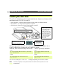
1
Mobile Printing Axis Communications Technical Support Should you require any technical assistance, please contact your Axis reseller. If your questions cannot be answered immediately, your reseller will forward your queries through the appropriate channels to ensure a rapid response. If you are connected to the Internet, you can: ■ Download user documentation and firmware updates. ■ Find answers to previously resolved problems in the FAQ database. Search by product, category or phrases. ■ Report problems to Axis support staff by logging in to your private support area. Visit the Axis Support Web at www.axis.com/techsup/ User’s Manual AXIS 250S Part No: 19194 Revision: 1.0 Date: May 2002 www.axis.com ©2002, Axis Communications AB. Axis and the Axis logo are registered trademarks of Axis Communications AB. All other company names and products are trademarks or registered trademarks of their respective companies. We reserve the right to introduce modifications without notice. Network Video Server U s e r ’s M a n u a l AXIS 250S MPEG-2 Video Server DVD-quality video over networks 2 AXIS 250S User’s Manual About This Document This manual is intended for administrators and operators of the AXIS 250S MPEG-2 Video Server, and is applicable for firmware release 3.0. Later versions of the document will be posted to the Axis Web site, as required. Previous experience of networking will be of use to the reader when installing and using this product. Some knowledge of UNIX or Linux-based systems would also be beneficial, for developing custom programming scripts and applications. Safety Notices Please observe all safety notices when using this product. Caution! - Potential hazard that can damage the product. Important! - Potential hazard that can seriously impair operation. Do not proceed beyond any of the above notices until you have fully understood the implications. Legal Considerations Camera surveillance may be prohibited by laws that vary from country to country. Check the laws in your local region before using the AXIS 250S for surveillance. The AXIS 250S includes 3 viewer licenses. The installation of more than 3 instances of the viewer is prohibited. To purchase further licenses, please contact your Axis reseller. Electromagnetic Compatibility (EMC) USA - This equipment has been tested and found to comply with the limits for a Class B digital device, pursuant to Part 15 of the FCC Rules. These limits are designed to provide reasonable protection against harmful interference in a residential installation. This equipment generates, uses and can radiate radio frequency energy and, if not installed and used in accordance with the instructions, may cause harmful interference to radio communications. However, there is no guarantee that interference will not occur in a particular installation. If this equipment does cause harmful interference to radio or television reception, which can be determined by turning the equipment off and on, the user is encouraged to try to correct the interference by one or more of the following measures: Reorient or relocate the receiving antenna. Increase the separation between the equipment and receiver. Connect the equipment into an outlet on a circuit different from that to which the receiver is connected. Consult the dealer or an experienced radio/TV technician for help. Shielded (STP) network cables must be used with this unit AXIS COMMUNICATIONS <Product Name> Quick User’s to ensure compliance with the class BGuide limits. Europe - The AXIS 250S fulfills the requirements for radiated emission according to limit B of EN55022:1998. When using the Line input, the AXIS 250S also meets the requirements for immunity according to EN55024:1998 residential, commercial, and light industry. The Mic input may be subject to interference from nearby radio transmissions. For best performance, use the Line input. Liability Every care has been taken in the preparation of this manual. Please inform your local Axis office of any inaccuracies or omissions. Axis Communications AB cannot be held responsible for any technical or typographical errors and reserves the right to make changes to the product and manuals without prior notice. Axis Communications AB makes no warranty of any kind with regard to the material contained within this document, including, but not limited to, the implied warranties of merchantability and fitness for a particular purpose. Axis Communications AB shall not be liable nor responsible for incidental or consequential damages in connection with the furnishing, performance or use of this material. Trademark Acknowledgments Acrobat, Adobe, Boa, Ethernet, IBM, Internet Explorer, LAN Manager, Linux, Macintosh, Microsoft, Netscape Navigator, OS/2, UNIX, Windows, WWW are registered trademarks of the respective holders. Java and all Java-based trademarks and logos are trademarks or registered trademarks of Sun Microsystems, Inc. in the United States and other countries. Axis Communications AB is independent of Sun Microsystems Inc. Axis Support Services Should you require any technical assistance, please contact your Axis reseller. If your questions cannot be answered immediately, your reseller will forward your queries through the appropriate channels to ensure a rapid response. If you are connected to the Internet, you can: • Download user documentation and firmware updates. • Find answers to resolved problems in the FAQ database. Search by product, category, or phrases. • Report problems to Axis support staff by logging in to your private support area. Visit the Axis Support Web at www.axis.com/techsup/ AXIS 250S MPEG-2 Video Server User’s Manual. Revision 1.01 Part No: 19194 Dated: August 2002 Copyright © Axis Communications AB, 2002 AXIS 250S User’s Manual Table Of Contents Introduction . . . . . . . . . . . . . . . . . . . . . . . . . . . . . . . . . . . . . . . . . . . . . . . . . . . . . 5 Features and Benefits . . . . . . . . . . . . . . . . . . . . . . . . . . . . . . . . . . . . . . . . . . . . . . . . . . 5 Applications . . . . . . . . . . . . . . . . . . . . . . . . . . . . . . . . . . . . . . . . . . . . . . . . . . . . . . . . . . 7 Product Description . . . . . . . . . . . . . . . . . . . . . . . . . . . . . . . . . . . . . . . . . . . . . . . . 8 AXIS 250S Front Panel . . . . . . . . . . . . . . . . . . . . . . . . . . . . . . . . . . . . . . . . . . . . . . . . . . 8 AXIS 250S Rear Panel . . . . . . . . . . . . . . . . . . . . . . . . . . . . . . . . . . . . . . . . . . . . . . . . . . 8 Hardware Inventory . . . . . . . . . . . . . . . . . . . . . . . . . . . . . . . . . . . . . . . . . . . . . . . . . . . . 9 Installing the AXIS 250S . . . . . . . . . . . . . . . . . . . . . . . . . . . . . . . . . . . . . . . . . . . 10 Client System Requirements . . . . . . . . . . . . . . . . . . . . . . . . . . . . . . . . . . . . . . . . . . . . 11 Installing the AXIS MPEG-2 Viewer (Client) . . . . . . . . . . . . . . . . . . . . . . . . . . . . . . . . . 12 Accessing the AXIS 250S from Internet Explorer . . . . . . . . . . . . . . . . . . . . . . . . . . . . . 13 Configuring the video source and audio equipment . . . . . . . . . . . . . . . . . . . . . . . . . . . 13 Operating the AXIS 250S . . . . . . . . . . . . . . . . . . . . . . . . . . . . . . . . . . . . . . . . . . 14 Accessing and logging on to the AXIS 250S . . . . . . . . . . . . . . . . . . . . . . . . . . . . . . . . 14 Access from a browser . . . . . . . . . . . . . . . . . . . . . . . . . . . . . . . . . . . . . . . . . . . . . . . . . 15 The Live View Page . . . . . . . . . . . . . . . . . . . . . . . . . . . . . . . . . . . . . . . . . . . . . . . . . . . 15 Events and Event Types . . . . . . . . . . . . . . . . . . . . . . . . . . . . . . . . . . . . . . . . . . . . . . . . 17 Upload Servers . . . . . . . . . . . . . . . . . . . . . . . . . . . . . . . . . . . . . . . . . . . . . . . . . . . . . . . 20 Notification Servers . . . . . . . . . . . . . . . . . . . . . . . . . . . . . . . . . . . . . . . . . . . . . . . . . . . 21 Audio & Video Settings . . . . . . . . . . . . . . . . . . . . . . . . . . . . . . . . . . . . . . . . . . . . . . . . 22 Port Status & Devices . . . . . . . . . . . . . . . . . . . . . . . . . . . . . . . . . . . . . . . . . . . . . . . . . 23 Live View Layout . . . . . . . . . . . . . . . . . . . . . . . . . . . . . . . . . . . . . . . . . . . . . . . . . . . . . 25 Administration & System Options . . . . . . . . . . . . . . . . . . . . . . . . . . . . . . . . . . . . 26 Users . . . . . . . . . . . . . . . . . . . . . . . . . . . . . . . . . . . . . . . . . . . . . . . . . . . . . . . . . . . . . . 27 Firewall Settings . . . . . . . . . . . . . . . . . . . . . . . . . . . . . . . . . . . . . . . . . . . . . . . . . . . . . 28 Date & Time . . . . . . . . . . . . . . . . . . . . . . . . . . . . . . . . . . . . . . . . . . . . . . . . . . . . . . . . . 29 TCP/IP Network Settings . . . . . . . . . . . . . . . . . . . . . . . . . . . . . . . . . . . . . . . . . . . . . . . 30 SMTP (email) Network Settings . . . . . . . . . . . . . . . . . . . . . . . . . . . . . . . . . . . . . . . . . 32 Ports & Devices . . . . . . . . . . . . . . . . . . . . . . . . . . . . . . . . . . . . . . . . . . . . . . . . . . . . . . 32 Maintenance . . . . . . . . . . . . . . . . . . . . . . . . . . . . . . . . . . . . . . . . . . . . . . . . . . . . . . . . 33 Support - Logs & Reports . . . . . . . . . . . . . . . . . . . . . . . . . . . . . . . . . . . . . . . . . . . . . . 33 The Factory Default Settings . . . . . . . . . . . . . . . . . . . . . . . . . . . . . . . . . . . . . . . . . . . . 34 Appendix A - Other IP Setup Methods . . . . . . . . . . . . . . . . . . . . . . . . . . . . . . . . . 35 Using the AXIS IP Installer . . . . . . . . . . . . . . . . . . . . . . . . . . . . . . . . . . . . . . . . . . . . . . 35 Appendix B - Troubleshooting . . . . . . . . . . . . . . . . . . . . . . . . . . . . . . . . . . . . . . . 37 PINGing Your IP Address . . . . . . . . . . . . . . . . . . . . . . . . . . . . . . . . . . . . . . . . . . . . . . . 38 3 4 AXIS 250S User’s Manual Appendix C - Updating the Firmware . . . . . . . . . . . . . . . . . . . . . . . . . . . . . . . . . . 41 Obtaining Updated firmware . . . . . . . . . . . . . . . . . . . . . . . . . . . . . . . . . . . . . . . . . . . . 41 Updating the firmware . . . . . . . . . . . . . . . . . . . . . . . . . . . . . . . . . . . . . . . . . . . . . . . . . 41 Appendix D - Customizing The AXIS 250S . . . . . . . . . . . . . . . . . . . . . . . . . . . . . . 42 Modifying the File System . . . . . . . . . . . . . . . . . . . . . . . . . . . . . . . . . . . . . . . . . . . . . . 42 Configuration via FTP . . . . . . . . . . . . . . . . . . . . . . . . . . . . . . . . . . . . . . . . . . . . . . . . . . 42 Custom Web Pages . . . . . . . . . . . . . . . . . . . . . . . . . . . . . . . . . . . . . . . . . . . . . . . . . . . 43 Appendix E - Unit Connections . . . . . . . . . . . . . . . . . . . . . . . . . . . . . . . . . . . . . . 46 The D-Sub Connector . . . . . . . . . . . . . . . . . . . . . . . . . . . . . . . . . . . . . . . . . . . . . . . . . . 46 The I/O Terminal Blocks . . . . . . . . . . . . . . . . . . . . . . . . . . . . . . . . . . . . . . . . . . . . . . . . 46 Connecting Pan/Tilt Devices . . . . . . . . . . . . . . . . . . . . . . . . . . . . . . . . . . . . . . . . . . . . . 48 Controlling and Monitoring . . . . . . . . . . . . . . . . . . . . . . . . . . . . . . . . . . . . . . . . . . . . . 49 Appendix F - Technical Specifications . . . . . . . . . . . . . . . . . . . . . . . . . . . . . . . . . 51 Appendix G - Bandwidth . . . . . . . . . . . . . . . . . . . . . . . . . . . . . . . . . . . . . . . . . . . 53 The Video Bit Rate . . . . . . . . . . . . . . . . . . . . . . . . . . . . . . . . . . . . . . . . . . . . . . . . . . . . 53 Image Quality vs Bit Rate . . . . . . . . . . . . . . . . . . . . . . . . . . . . . . . . . . . . . . . . . . . . . . 53 Other Considerations . . . . . . . . . . . . . . . . . . . . . . . . . . . . . . . . . . . . . . . . . . . . . . . . . . 54 Index . . . . . . . . . . . . . . . . . . . . . . . . . . . . . . . . . . . . . . . . . . . . . . . . . . . . . . . . . . 55 AXIS 250S User’s Manual Introduction Introduction The AXIS 250S MPEG-2 Video Server is a one-port MPEG-2 video server that allows real-time compression and transmission of DVD quality MPEG-2 video streams over a TCP/IP network (LAN). The video stream uses approximately a third of the bandwidth required by a Motion-JPEG stream. The AXIS 250S includes all of the required networking connectivity for distributing analog video over the network. The built-in Web server provides its own application page for direct viewing of the video stream, as well as full web-based control of the management and configuration functions. All of this can be accessed from a browser over the network. TCP/IP, SMTP, HTTP and other Internet-related protocols are supported. The AXIS 250S MPEG-2 Video Server Features and Benefits Complete & independent - The AXIS 250S runs independently of any other server and, apart from a camera and audio equipment, requires no other hardware. To view live video streams and configure the product over the network, all that is needed is Microsoft® Internet Explorer 5.5 or higher, Microsoft Media Player, and DirectX®. These components are all included with Microsoft Windows 2000 and XP. Please see page 11 for the exact versions required. Microsoft Media Player is used with the AXIS MPEG-2 Viewer (included) to view the video stream. The product includes one encoder and three decoder (viewing) licenses. TCP/IP, SMTP, HTTP and other Internet-related protocols are supported. Superior Imaging - MPEG-2 hardware compression and transmission technology uses approximately 1/3 of the bandwidth required by a Motion-JPEG stream of comparative quality. The video stream can be viewed by up to 3 clients on a LAN and full frame rate (25/30 frames per second) is assured, provided that bandwidth is available. Available image resolutions are: 720x576 or 352x288 (PAL) and 720x480, 352x240 (NTSC). The bit rate is configurable. Support for high performance video cards with hardware acceleration on clients. 5 6 Introduction AXIS 250S User’s Manual The on-board AXIS ETRAX 100-LX processor provides up to 25/30 frames/second over 10Mbps or 100Mbps networks. Configurable event types - Remote storage of MPEG-2 video recordings to FTP-servers, and/or activation of external devices. Possible to enable a pre-alarm video buffer, allowing up to 1 minute of video to be buffered in the server and transmitted when the event occurs. Users can also be notified of events by email. External Device Connection - Supporting the RS-232 and RS-485 communication protocols, the AXIS 250S includes the physical interfaces for connecting a variety of external devices; such as, Pan/Tilt/Zoom devices, doorbells, switches and alarm relays. Develop your own programing scripts for creating a variety of security applications triggered on time or alarm-based events. You can even drive annunciators and other audible alarm devices using the relay output. Fully utilizes high quality audio equipment for surveillance. 4 alarm inputs allow connection of e.g. sensors for triggering events and recordings. 1 digital output allows the server to trigger external devices. Audio and Video inputs - 1 BNC composite video input for connecting a CCTV camera. 1 S-Video input for connecting S-Video cameras or other video equipment. 1 stereo microphone input for connection of high quality microphones. 2 discrete amplification steps available. 1 stereo line input for connecting audio sources providing amplified audio signals. Security - Multi-user and multi-level password protection. Administrators can create and modify accounts for authorized users, as well as allow anonymous viewing. The built-in firewall provides IP-filtering, thus preventing unauthorized access. Linux Operating System - The AXIS 250S includes modified versions of the Boa Web server, and Linux operating system - both of which are freely distributed under the GNU General Public License, as published by the Free Software Foundation. This software provides a stable and reliable platform for open-source development of the product. In accordance with the GNU General Public License, Axis has published the kernel for this product at http://developer.axis.com/. AXIS 250S User’s Manual Introduction Applications The AXIS 250S MPEG-2 Video Server can be used in a wide range of surveillance and monitoring applications, and is the perfect choice where an application requires a high-quality video and audio stream to be distributed at a fixed frame rate over a local area network (LAN). The AXIS 250S can also upload video sequences to web/ftp servers, for indirect access over the Internet. With direct access from your browser, you can view live video, and manage and control the AXIS 250S at any time, from anywhere on the network. The AXIS 250S’s sophisticated features make it the ideal tool for intruder detection, industrial process control, public surveillance and visual security. • • • • Live video monitoring by up to 3 clients on LAN Continuous storage of video on external server Event notification Pre-trigger and post-trigger video capture 7 8 Product Description AXIS 250S User’s Manual Product Description Read the following information to familiarize yourself with the AXIS 250S, making particular note of where the connectors and indicators are located. AXIS 250S Front Panel ❶Factory Default Button ❻ - Press this button to restore the factory default settings, as described on page 34. ❶ ❷Microphone Connector ❸Line Connector ❷ ❹Y/C Video Input (S-Video) - Physical connections ❸ ❹ ❺ made using s-video cable. ❺Switch for selecting 75 ohm video termination (for BNC). Usually set to ON. ❻ Video Input (BNC) - coax/BNC connector. Connections using RG59, 75 Ohm coax video cable have a recommended maximum length of 800 feet (250 meters). AXIS 250S Rear Panel ❷ ❶I/O Terminal Block A Provides the physical interfaces to one transistor output, two digital inputs, and GND. Used for connecting external devices typically associated with CCTV equipment. See also page 46. ❸ ❹ ❶ ❷Power Supply Connector - A single socket (PS-K) for connection of the ❺ ❻ AXIS 250S power supply. Alternative power supply = 7-20V DC. ❸RS-232 Serial Connector - Used for connecting Pan/Tilt/Zoom devices, etc. ❹RJ45 Network Connector - Variable data communication speed (10-100 Mbps). ❺Indicator LEDs - The Power LED shows steady green for normal operation, or flashing green or unlit for a malfunction in the power supply. It will also flash amber during a firmware upgrade. The Status LED shows steady green for normal operation, or red for critical errors. The Network LED flashes amber for 10Mbps network activity, flashes green for 100Mbps network activity, or shows solid red for no network connection. An unlit indicator denotes no activity. ❻I/O Terminal Block B - Provides the physical interfaces to RS-485 Pan Tilt devices and 2 digital inputs. See page 46 for pinout information. AXIS 250S User’s Manual Product Description Hardware Inventory Check the items supplied with your AXIS 250S against the following list: Item Title/Variant AXIS 250S MPEG-2 Video Server Part Number 0159-001-01* Item Power Supply (PS-K) ** Title/Variants Part Numbers Europe UK USA Japan Australia Terminal Connectors x2 16817 This Document AXIS 250S User’s Manual v1.0 19194 Warranty Document - 18640 Disk Media AXIS Product CD 1.0 (or later) 19114 License letter - 19331 Mounting kit - 18855 Notes: •*The label on the carton containing your AXIS 250S will show the part number for the country of purchase. •**The power supply for your AXIS 250S is country-specific. Please check that the type you are using is correct. 9 10 Installing the AXIS 250S AXIS 250S User’s Manual Installing the AXIS 250S This section is intended for use by the product administrator. Operators and viewers should read Operating the AXIS 250S, on page 14. • Quick installation - Follow the instructions below to quickly install on an Ethernet network. • Easy installation - See Using the AXIS IP Installer, on page 35. • Other Methods - Please refer to Other IP Setup Methods, on page 35. ❷Connect a video source to the BNC or S-Video connector. (Use a BNC-to-RCA converter if your source is supplied with a phono-type (RCA) connector.) The 75 Ohm selector switch should normally be set to ON. If the unit is connected in parallel (e.g. with a monitor) set this switch to OFF. ❶Connect a microphone to the Mic connector, or an alternative input device to the Line input. ❸Note the Serial number on the underside of the unit. You need to know this to set the IP address. Serial number same as Ethernet address; e.g. 00408c100086 = 00-40-8c-10-00-86 ❹ Using an appropriate method for your operating system, assign your product with a unique IP address from a computer on your network, as follows: Windows only - Start a Command prompt and type these commands: UNIX only - Type this in your command line: Syntax: Syntax: arp -s <Server IP address> <Ethernet address> <my PC IP address> ping -t <Server IP address> arp -s <IP address> <Ethernet address> temp ping <IP address> Example: Example: arp -s 172.21.1.200 00-40-8c-10-00-86 172.21.1.193 ping -t 172.21.1.200 arp -s 172.21.1.200 00:40:8c:10:00:86 temp ping 172.21.1.200 You will now see ‘Request timed out...’ messages repeatedly returned in the window. Note: In some Unix systems, the arp command can be located in a directory that is not on the command path. AXIS 250S User’s Manual Installing the AXIS 250S ❺ Connect an Ethernet cable to the AXIS 250S and attach it to the network. ❻Connect the power cable to the unit and connect it to your main power supply. Power Indicator Network Indicator Status Indicator ❼ Approximately 10-15 seconds after connecting the power supply, the message ‘Reply from 172.21.1.200...’ - or similar, is returned within the window. Ensure that the Power Indicator is permanently lit and that the Network Indicator flashes intermittently. ❽ Exit ping. The installation is now complete. You can now access the server directly from your browser, as described below. Client System Requirements Client computers that will be viewing the video stream from the AXIS 250S MPEG-2 Video Server should meet the following hardware and software requirements: • • • • • • • • Intel Pentium III 500MHz processor, or better 128 MB RAM AGP Graphics card with 16 MB video memory and support for DirectDraw® 32-bit color, if running more than one video stream at a time Windows® 2000 or Windows XP Internet Explorer 5.5 or higher Windows Media Player 7.1 or higher DirectX® v 8.1 or higher 11 12 Installing the AXIS 250S AXIS 250S User’s Manual Installing the AXIS MPEG-2 Viewer (Client) The first time the AXIS 250S is accessed from a browser, the AXIS MPEG-2 Viewer will automatically be installed. This component is required for viewing the video stream in the browser. Simply accept the license agreement displayed in the setup window and the client will install. Important! • The AXIS 250S is supplied with three (3) licenses for the AXIS MPEG-2 Viewer. Installing more than 3 instances of the viewer contravenes the terms of the license agreement and is prohibited. To purchase further licenses, please contact your Axis reseller. • To allow the installation of the AXIS 250S MPEG-2 Viewer, set your browser to allow the installation of signed ActiveX controls. This is the default setting in Internet Explorer. • The AXIS MPEG-2 Viewer can be uninstalled from “Add/Remove programs” in the Windows Control Panel. After the installation has completed restart your computer, if required. After the client is installed, there will be a new icon in the Windows Control Panel. Clicking on this icon opens the properties tool for the client. There are now a number of settings that can be made. These are: Network Connection Timeout - This value is the maximum length of time in seconds that the client will attempt to connect to the server, before displaying an error message. The default setting is 15 seconds. Set the AXIS MPEG-2 decoder as the default viewing codec - selecting this option means that the AXIS MPEG-2 Viewer client will always be used to view MPEG-2 video streams. Note that installing other decoders at a later date may override this setting. AXIS 250S User’s Manual Installing the AXIS 250S Accessing the AXIS 250S from Internet Explorer ❶ Start your browser and enter the IP address of the AXIS 250S in the location/address field. The first time the server is accessed, there will be no need to log in. ❷ The main application page now opens, allowing you proceed with the product’s configuration by clicking on the Setup link. Important! Upon delivery, the AXIS 250S is supplied with one pre-configured Administrator user name and password, set to root and pass, respectively. The Administrator password should be changed as soon as possible, to prevent unauthorized access to the setup tools and/or the video stream. Configuring the video source and audio equipment You should now configure the connected video source and audio equipment: 1. From the administration tools, open the Video settings page. 2. Select the physical connector the camera or other equipment is connected to. 3. Set the Source modulation to the correct type for your camera. NTSC is the standard in the United States and PAL is the standard used in Europe. If unsure, check the documentation supplied with the camera. 4. Open the Audio settings page. 5. Select the audio input you connected your equipment to. 6. Enable audio, set the desired audio quality, and set the Mic Input Sensitivity according to your microphone. Click Save and then return to the Live View page to view the video stream. See also the configuration section for audio and video on page 22. 13 14 Operating the AXIS 250S AXIS 250S User’s Manual Operating the AXIS 250S This section is intended mainly for system Operators, that is, personnel responsible for using the AXIS 250S as part of e.g. an integrated surveillance system or similar. Although the topics covered here relate to the everyday running of the system, product Administrators will also find this section useful reading. The following topics are covered: • • • • • • accessing the AXIS 250S MPEG-2 Video Server adding and modifying event types configuring upload servers editing audio and video settings checking port and device status changing the layout of the Live View page. For more information on configuring the AXIS 250S at the Administrator level, please refer to Administration & System Options, on page 26. Accessing and logging on to the AXIS 250S The AXIS 250S allows several levels of access and generally requires the user to log on. The various types allow different degrees of control and some options/controls are not available at the lower levels. One of the product administrator’s first tasks should be to create and define the users allowed to access the server. For more information on managing users, see Users, on page 27. An operator will have access to the server’s main application page, as well as certain other functions and controls - in short, everything not included in the System Options, which are only available to administrators. The only exception to the logon requirement is if the server has been configured to allow anonymous viewing access and an anonymous user connects to the server. Important! Your system Administrator has installed the AXIS 250S on your computer network, connected a surveillance video camera to the unit, and tailored the functions and look and feel of the system to meet your specific surveillance needs. Consequently, the examples provided here may differ from those displayed in your system. Any problems with your application should be referred to your system administrator. AXIS 250S User’s Manual Operating the AXIS 250S Access from a browser The video stream and the setup tools in the AXIS 250S can be accessed using Microsoft Internet Explorer 5.5 on Windows 2000 or Windows XP. Follow the instructions below to access your images: 1. Start Internet Explorer. 2. Enter the name or IP address of the AXIS 250S into the Address bar: Example! http://172.21.1.200/ The Live View page, similar to the example shown below, is now displayed. Note: To enable the viewing of the MPEG-2 video stream in Microsoft Internet Explorer, you must set your browser to allow signed ActiveX controls and install the AXIS 250S MPEG-2 Viewer onto your workstation. This will be performed automatically the first time the server is accessed. The Live View Page The page available to all user levels when accessing the AXIS 250S MPEG-2 Video Server is known as the Live View page. This page shows the server’s basic application, that is, a live MPEG-2 video stream from the connected camera. If there is a Pan/Tilt/Zoom device connected and configured, it will be possible to control it from this page. The Live View page can be viewed simultaneously by up to 3 clients. Link to setup tools Play/pause button Stop button Volume slider Mute button 15 16 Operating the AXIS 250S AXIS 250S User’s Manual Disconnected Video Source Any problem with the camera or video source is indicated by a blank display. This may indicate a break in the signal transmission or the cable, and any such incident should be immediately referred to your system administrator. Positional Control of the Video Source Video cameras supporting Pan Tilt and Zoom (PTZ) are connected and controlled directly from the server’s ports. A PTZ-configured video source is automatically displayed with Pan, Tilt and Zoom bars, as shown in the illustration below: Notes: •The AXIS 250S can control a range of relative and absolute PTZ devices via the Web interface, or via a third-party application. The positioning tools provided depend on the selected PTZ device. Other functions, not shown in the illustration, may also be available. •PTZ controls can be disabled in the Live View layout settings and may be unavailable in the user interface. •Clicking anywhere on a toolbar’s gradient allows for a “smooth” PTZ adjustment; whereas clicking on the left or right arrows causes a stepped incremental change. Zoom Allows smooth or stepped camera zoom between telescopic and wide viewing. Select Preset Position To enable quick and accurate camera positioning, up to 20 preset camera positions can be set and selected at any time from the drop-down dialog. Pan Allows smooth or stepped horizontal panning of the camera. Tilt Allows smooth or stepped vertical panning of the camera. Home (H) Returns the camera to the ‘Home’ position. AXIS 250S User’s Manual Operating the AXIS 250S Events and Event Types Your AXIS 250S MPEG-2 Video Server is capable of performing various actions when certain types of events occur. The terminology used to describe this is as follows: • Event type - a defined set of parameters that specify how and when something will trigger an action. • Event - one occurrence of an event type. • Action - what occurs when the event triggers. Examples are the upload of video to an FTP server, email notification, etc. • Trigger - the circumstances that start an event. This could be e.g. a pre-programmed time or a signal from an external device, such as a door switch or a motion sensor. Configuring Event Types An event type is a set of parameters describing how and when the server will perform certain actions. An event type may result in one single event, or it may result in many, depending on its configuration. The most common kind of event type will trigger the upload of images to a specified destination. Other actions performed by event types can include the sending of e-mail, the activation of the output port and various types of event notification. Setting up a new event type Click the menu link to Event Types. This opens the list of event types as in the example below. The list shows various information about the event types currently configured. 17 18 Operating the AXIS 250S AXIS 250S User’s Manual Click the Add button. This launches the Event Type Setup dialog. Depending on the event type you require, you will then need to provide some or all of the following information: General • Name - Give the event type a suitable name. Respond to Trigger... This setting determines when the event type can be activated. The options are: • Always - the event type can be activated by the trigger (see below) at any time • Only during time frame - a trigger will only start the event type during the times specified. Triggers at other times will be ignored. Select the days and set the period’s start time and duration. The duration may be set up to a maximum of 168 hours. If a duration of more than 24 hours is required, then only one weekday may be checked. To use two or more trigger time frames longer than 24 hours - two or more event types (one for each period) must be configured. • Never - the event type is disabled and no actions will be performed. Trigger Type The trigger type is what starts the event type. The following options are available: • Input Ports - This describes the states that the 4 inputs must be in before the event type is triggered. One or more inputs can be used together, but note that the states for all the inputs used must first be reached before the event type is triggered. • Timer - whole time frame - This option will simply use the times specified in Respond to Trigger... described above. • Timer - periodically - Use this to trigger the event type at a certain frequency. Configurable in seconds, minutes or hours. It is also possible to specify the time to commence triggering. Note that this setting also uses the times specified in Respond to Trigger... • Loss of Video - If the video signal disappears, this will trigger the event. A notification of the event would be a suitable action for this trigger. If the event type has been configured to upload a video sequence for this trigger, then this will, of necessity, only be the pre-trigger sequence, if this has been enabled. • Server Boot - This can be used to trigger the event type whenever the server is started or restarted. A notification of the event would be a suitable action for this trigger type. • Log Messages - The server can trigger an event type whenever a system event writes an entry to a log file. There are three types of log file; Information, Warning or Critical. Select the level that will trigger the event. Note that the first two alternatives also include messages of a higher importance, so alternative 1 will trigger the event type the most, as it also includes Warning and Critical log messages. AXIS 250S User’s Manual Operating the AXIS 250S • Manual Trigger - This is used for manually starting and stopping the event. It is also possible to use this option to trigger the event via the server’s API. When Triggered... These settings describe the actions to take when the event type is triggered. One or more actions may be selected. • Upload to FTP server - Select the FTP server to upload images to. Note that FTP servers must first be configured in Upload Servers. See page 20. • Upload for - Specify the total time to upload the recording. Configurable in seconds, minutes or hours. This can be used to continue the upload even after the event has ended. • Upload as long as trigger is active - This option will terminate the upload as soon as the event ends. • Split upload into - Use this to split a long video sequence into several shorter sequences. Configurable in seconds, minutes or hours. This is recommended if there is likely to be recordings longer than 30 minutes in duration. The AXIS 250S can easily handle video files of more than 30 minutes, but they may cause problems for some types of FTP server. • Include pre-trigger recording - The AXIS 250S is capable of saving video sequences that originate from the time immediately before the trigger. This can be very useful when checking to see what happened to cause the trigger. Check the box to enable. Important! Note that to use pre-trigger recording in event types, pre-trigger recording must first be enabled in the Video settings. • Base file name - This name will be used for all of the files saved. If suffixes are also used, the file name will take the form filename_suffix. • Add suffix - Add either a date/time suffix, a sequence number (with or without a maximum value), or select Overwrite. This last option will save one file only and will constantly overwrite it, whereas using sequential numbering with a maximum will overwrite the first file as soon as the last file is written. • Activate output port - This box must be checked to enable the use of the output port. The port is used to control external equipment. • Keep active during event - This option allows external equipment to be run/controlled for the entire duration of the event. This might be necessary to e.g. keep extra lighting on while saving/uploading a video sequence. • Keep active for - Specify a fixed length of time the port will be active for. 19 20 Operating the AXIS 250S AXIS 250S User’s Manual Important! Please keep in mind that the output port can be controlled by more than one event type. This may mean that the port is the “wrong” state if one or more event types that activate the port are triggered one after the other. Using more than one event type to control the output is not recommended. • Send email notification to - Check this box to enable the sending of email to notify recipients of events. Enter the email address(es) in the field provided. Multiple addresses must be separated by semicolons (;) To add your own text, check the Include text box and enter your text. Note that a mail server must be configured in the SMTP network settings. • Send HTTP notification - This method sends a notification to an HTTP server. Select the name of the server. Note that the destination server must first be configured in Notification Servers. See the following page. • Send TCP notification - This method sends a TCP/IP notification. The destination server must also first be configured in Notification Servers. Click OK to save the event type setup. Upload Servers Clicking this link will open the list of FTP servers currently configured in the server. The listing shows the name and address of the server, as well as the upload path and user name. Adding an Upload Server Click the Add button. This opens the Upload Server Setup dialog. The following information should then be provided for the new server. • Name - This can be any descriptive name you like. • Network address - Enter the IP address or host name of the server. To use a host name, a DNS server must be specified in the TCP/IP network settings. • Upload path - Specify the path to the directory where the uploaded images will be stored. If this directory does not already exist on the ftp server, there will be an error message when uploading. • Additional information - In this field you can add extra information about the server. For example, if the saved video files can also be accessed via a UNC address (e.g. \\video\file1.mpeg), then you could add text providing this address. This information will be included in email sent by events that use this server. • The user name and password you use to log on to the server. When finished, you can test the setup by clicking the Connect button. The results of the connection test will then be displayed in a message box. AXIS 250S User’s Manual Operating the AXIS 250S Notification Servers To allow your event types to send HTTP and TCP notifications, the necessary servers must first be configured. The Notification Server list shows the servers currently configured. These severs are shown as the alternatives when selecting this type of notification in the event type setup, as described in the preceding section. Note that event notification server settings have nothing to do with the change of IP address notification settings. HTTP Notification An HTTP notification normally requires some sort of script to be located on the destination server. This script reads the parameters sent in the notification and then performs some sort of action. The following information should be provided for an HTTP notification server: • Name - This can be any name you like. • URL - In this field you should provide the IP or host address of the server, the path to your script, and finally the name of the script. For example: http://server/path_to_script/script.cgi • Custom Parameters - Enter your own text here. See also below. • User name/password - If you need to supply a user name and password to access the HTTP server, provide these here. • Proxy/Proxy port - If you must pass a proxy server to access the HTTP server, provide the server’s network address and the port used for access. • Proxy user name/password - The proxy server may require a user name and password. • Retry count - If the connection attempt fails, enter the number of times to retry. • Message - Enter your own text here. This will be displayed in the notification. This is then what is actually included when the HTTP notification is sent: http://server/path/script.cgi?Eventname=MyEvent&Message=MyMessage&Custom For the Custom field the following should be noted: • The field must be named as a parameter for it to work. For example: http://servername/...................&CustomParameter=MyTextHere. • The field must be manually URL-encoded. This means that to use special characters, these must be coded and not simply typed. For example, to include a blank space, type %20 instead. The equal sign (=) can be typed directly. 21 22 Operating the AXIS 250S AXIS 250S User’s Manual The following information should be provided for a TCP notification server: • Name - This can be any descriptive name you like. • Network address - Provide the address of the server here. This may be an IP address or a host name. Note that to use a host name, a DNS server must be configured in the TCP/IP network settings. • Port - Enter the port number used for accessing the TCP host. • Retry count - If the connection attempt fails, enter the number of times to retry. • Message - Enter your own text here. This will be displayed in the notification. Click OK to save the notification server settings. Audio & Video Settings Video The AXIS 250S provides the connection for a single analog camera (or other video source), on either the BNC connector or the S-Video connector. Ensure that the camera is correctly connected and powered up before attempting configuration. • Resolution - the two video resolutions available are CIF and 4CIF. The exact resolution will depend on the type of camera being used, PAL or NTSC. See also Technical Specifications, on page 51. • Color - Select either Color or Black & White. Black & White will provide sharper images at a lower bandwidth than Color. • Bit rate - This setting determines how much of the available bandwidth will be used by the video stream. The bit rate is configurable from 250 to 8000 kBit/s (8 MBit/s). See also Bandwidth, on page 53. • Input - Select the input the video source is connected to. The following options are available: • BNC (composite video) - connects a standard video camera or other video source. • Y/C (S-video) - connects an s-video camera or other video equipment. • Source modulation - The AXIS 250S supports both of today's common video modulation standards. Select the correct standard from the drop-down list. • NTSC - delivering 525 lines of resolution at 60 half-frames per second, this is the common standard in the United States. • PAL - the dominant standard in Europe, delivering 625 lines at 50 half-frames per second. • Enable pre-trigger and/or Post-trigger recording - The AXIS 250S MPEG-2 Video Server is capable of recording directly before and/or after an event occurs. This is achieved by constantly buffering (and overwriting) a certain amount of the video stream into the internal memory. When the event is triggered, the memory contents are added to the actual recording. AXIS 250S User’s Manual Operating the AXIS 250S Exactly how much pre-trigger recording will be produced depends mainly on the bit rate setting. A high-quality video stream will occupy more of the internal memory and thus shorten the duration of the recording. The length of the pre-trigger recording in seconds can be roughly calculated by dividing 16 by the bit rate in Mbit/s. Important! Note that pre-trigger recording must be enabled in the video settings if you wish to use pre-trigger recording in event types. Audio The AXIS 250S provides a fully synchronized audio stream at up to CD quality. The following settings are available: • Quality - Select the bit rate and sample rate to use. Generally speaking, the higher the setting, the better the sound quality, but at the higher levels the difference might not be audible. The default value (128 kbps) provides good quality sound. • Volume Settings - The Master volume control should not normally need any adjustment. However, if you are using some other audio input device on the Line connector, and the audio level is not satisfactory, then this level may need to be changed. Configurable between -30 and 30 dB. • Mic input sensitivity - This setting should be set according to the specifications for the connected microphone. If the correct setting is used, there will be no need to adjust the Master volume level. The volume slider in the web interface will suffice for raising or lowering the volume when viewing the video stream. If you are unsure of the correct setting for your microphone, try both settings. • Audio Input - Select the input to use for the audio input. The options are: • Line - connects other audio input devices • Mic - connects a standard microphone Port Status & Devices Port Status Clicking this link will display a list showing the status for the 4 inputs and the 1 output. The inputs cannot be configured here - this must be done from the System options, which requires administrator access. If an input or the output has not been enabled by the administrator, then the port will be shown as “Not in use”. 23 24 Operating the AXIS 250S AXIS 250S User’s Manual Devices This section allows you to configure and use Pan/Tilt/Zoom devices with your AXIS 250S. Click the Modify button to open a new window allowing you to create/edit preset positions. Note that devices must have previously been added and configured by the product administrator. Preset position setup To add a new position, use the controls to steer the camera so that it points to the desired point. Then enter a descriptive name in the Current Position field and click Apply. You can also set any position as Home, by checking the box provided when that position is current. This position will then be the default position when the video stream is viewed in a browser. It is also possible to go directly to the Home position from any other position simply by clicking the H button at the bottom right corner. To remove a preset position, select it from the drop-down list and click Remove. AXIS 250S User’s Manual Operating the AXIS 250S Live View Layout The home page for the AXIS 250S MPEG-2 Video Server can be altered to your own requirements. Click the link to Live View Layout to open the Personal Settings. Most of the features on the Live View page can be customized. For example, you can quickly change the background color and include your corporate logo. Once you have enabled personal settings by checking the box, you can then change most aspects of the page. Simply select the item to use and then choose whether to use the default setting or to specify your own. For many of the items, selecting Own will also require you to specify the location for the resource, for example, the location of the background picture you wish to use. Note: Unchecking the Show Setup link will mean that the administration tools will then only be accessible by entering the full admin address into the browser’s URL field; for example: http://172.21.1.200/admin/. Please make a note of the address for your server, for future use. When you are satisfied with the new layout, click Save. 25 26 Administration & System Options AXIS 250S User’s Manual Administration & System Options This section lists and describes the administration tools used for the general configuration of the AXIS 250S - the System Options. The topics covered are, for example, network settings, date and time settings, users, etc. For information on general usage and how to set up event types, etc., please see Operating the AXIS 250S, on page 14. The product cannot be configured before it is installed. If you have not yet completed the installation, please refer to Installing the AXIS 250S, on page 10. Only the product’s administrator(s) is allowed access to these settings. Important Notes! • The default password (pass) for the pre-configured user (root) should be changed as soon as possible. Until this has been done, the security features in the product will not be enabled. Furthermore, all Axis products are shipped with the same password by default. For further information, refer to Users, on page 27. • When accessing the AXIS 250S for the first time, you will not be required to log in. • Javascript must be enabled in your browser for the AXIS 250S Web-based interface to work. Accessing The System Options The System Options can be used for configuring the AXIS 250S at any time. Follow the instructions below to access the System Options from your browser: 1. Start your browser and enter the IP address of the AXIS 250S in the address field, e.g. http://172.21.1.200 2. The first time the product is accessed there will be no need to log in. After the Live View page opens, click on the Setup link and then select the item you wish to configure from the System Options. The system is configured and modified directly from these pages. This can be done from any computer on the network that can access the unit. Note: On-line help is stored internally in the AXIS 250S and is available from the pages in the Web interface. Containing comprehensive details on all product parameters, the on-line help is your first point of reference when configuring and managing the unit, and is particularly useful for resolving any administration queries. AXIS 250S User’s Manual Administration & System Options System Options Overview The table below provides a brief overview of the System Options. Each section is explained in more detail in the pages that follow. Administration Security - Users Security - Firewall Settings Description Create and delete users and passwords, and modify the Administrator’s password. Protect your AXIS 250S against unauthorized access, using the built-in firewall. Allowed IP addresses and protocols can be specified. Date & Time Set the system time, manually or automatically. Network - TCP/IP Settings Configure TCP/IP settings, enable BOOTP/DHCP and restrict bandwidth. Network - SMTP (email) Configure SMTP-settings for sending e-mail messages notifying recipients of recordings, error Settings messages, system messages, etc. Ports & Devices - I/O Ports Enable and configure the 4 inputs and 1 output. Ports & Devices - COM Port Configure the COM-port for Generic TCP/IP, Generic HTTP or for a Pan Tilt Zoom device. Maintenance Provides tools for restarting the server and for resetting to the factory default settings. Support - Overview Provides links to various types of useful information, including how to contact Axis support services. Support - Logs & Reports Contains links to various log files and reports. Support - About Displays information about the development of the product. Users To prevent any unauthorized use of the product, the AXIS 250S supports multi-level and multi-user password protected access. A maximum of 20 users may be defined. An Administrator has unrestricted access to the product's administration tools and can determine the registration and rights for all other users. The Users List displays all of the users currently defined. The administrator user name (root) is permanent and cannot be deleted. The default password (pass), however, can and should be changed. See the important notes below. Important! • The default password (pass) for the pre-configured user (root) should be changed as soon as possible. Once this is done, the product’s security features will be enabled, and access to the Live View page and the Administration tools will be restricted to defined users only, unless Anonymous Login is also enabled, in which case anonymous access to the Live View page will be allowed. • Note also that if the root password is not changed, then the Enable anonymous viewer login checkbox will have no effect, checked or not. • The Enable anonymous viewer login checkbox will, after the root password has been changed, be disabled by default. • All Axis products are shipped with the same default Administrator password. • Changing the root password and, later, changing it back to pass will return the security function to its original state. 27 28 Administration & System Options AXIS 250S User’s Manual Adding Users Click Add to add a new user. The following fields must then be completed: • User Name - Must contain at least one, but not more than fourteen characters. • Password - Must contain at least one, but not more than eight characters. • Confirm Password - Repeat the above password here. User Group - Check the appropriate box to define the access rights and privileges for the new user, where the level of access can be described as follows: • Viewer - Provides the lowest level of access, which only allows the user to see live images. If the controls for a PTZ unit and/or the Trigger Event button are displayed on the application page, then a user with viewing rights will also be able to use these. • Operator - An Operator has access to all of the settings not included in the System Options, that is, he/she can add and edit settings for event types, upload servers, audio and video, etc. • Administrator - An Administrator has unrestricted access to the whole server and can consequently determine the registration of all other users. After making the settings for the new user, click the OK button. Editing and Deleting Users To edit or delete a user, highlight the name in the User list and click the Modify or Delete button. Firewall Settings The built-in firewall protects your AXIS 250S against unauthorized access. To restrict access, you can add IP addresses to the list of allowed addresses - no others will be permitted access. Enable/Disable Firewall - Click this button to enable or disable the firewall function. Allowed IP Addresses - This list box shows the currently configured IP addresses. Adding Allowed IP Addresses IP Address - Add a single IP address or a whole range of addresses. This last option can be useful if you have a large number of IP addresses that all need access to the MPEG-2 Video Server. To add a range of addresses type e.g. 192.168.0.* This will add all the addresses in the range 192.168.0.0 to 192.168.0.255. Up to 256 allowed IP addresses can be specified. AXIS 250S User’s Manual Administration & System Options Allowed Ports - Check the boxes for the protocols that the user (IP address) will be allowed to use to access the server. These can be FTP and/or HTTP. If you have particular requirements concerning which ports access will be allowed on, enter these in the Port range fields. To allow access via HTTP, the port value here must correspond to the value set on the TCP/IP Network Settings page. If this is set to some other value than 80 (the default setting), then this value must be added manually in this field. If the setting on the Network Settings page is 80, then nothing needs to be configured here. After adding the above information click the OK button to save the changes. Note: If you are accessing the AXIS 250S via a proxy server, the proxy server's IP address must be added to the list of allowed IP numbers. Deleting and Modifying the Properties for Allowed IP Addresses To delete an IP address, select it in the list and click the Remove button. To modify an IP address, select it from the list of allowed addresses, make the necessary changes and then click OK. Date & Time Click Date and Time to define the time and date settings for your AXIS 250S, either manually or automatically, as described below. Current Server Time Shows the current date and time. New Server Time Time Zone - Select the time zone where the AXIS 250S is located. Automatically adjust for daylight saving time changes - Check this box to automatically update the time changes caused by daylight saving. Synchronize with computer time - Sets the time according to the clock on your computer. Synchronize with NTP Server - This option will cause the AXIS 250S to update the time from an NTP server every 60 minutes. Specify the NTP server's IP address or DNS name and set the appropriate time zone for your server’s location. Note that if using a DNS name, a DNS server must be configured in the TCP/IP settings. Set manually - Using this option allows you to manually enter the time and date. 29 30 Administration & System Options AXIS 250S User’s Manual TCP/IP Network Settings From the Network Settings, configure the TCP/IP network settings as follows: Automatic IP Configuration DHCP - Dynamic Host Configuration Protocol (DHCP) is a protocol that lets network administrators centrally manage and automate the assignment of IP addresses in an organization's network. Check the box to allow a DHCP server on the network to assign the IP address. Important! DHCP should only be enabled if you are using dynamic IP address notification, or if your version of DHCP can update a DNS server, which then allows you to access the AXIS 250S by name. If DHCP is enabled and you cannot access the unit, you may have to reset it to the factory default settings (see page 34) and then perform the installation again (see page 10). BOOTP - Check this box to use BOOTP to automatically assign an IP address. Requires a BOOTP server on your system. BOOTP is enabled by default and is required for installation using the AXIS IP Installer. Dynamic IP Address Notification Settings When the IP address changes by means beyond your control, for example, by DHCP, you can choose to be notified of the change via HTTP, FTP or SMTP. Click the icon to display, edit and refine the settings for address notification. Referring to the table below, configure the dynamic IP address notification settings. Parameter Description HTTP Enabling HTTP means the server will send an HTTP GET request to the specified URL. This can then easily be taken care of by a designated cgi-script, which registers the request by some means. Custom parameters can be used by entering them in the field provided. The fields User Name and Password, should be used if the script is password protected. If you need to pass a proxy server to connect to the URL for the host, provide your user information in the relevant fields. SMTP Enabling SMTP will send an email notification of any change in IP address. Enter the recipient’s address and a sender’s address, as well as any text you want to appear in the subject of the email. Note that you must configure the mail server under Network Settings. FTP Saves a notification file on an FTP server. Provide the connection details for the server and your user name and password. If there is a firewall between the server and the FTP server, it is recommended that Passive Mode is enabled. There are 3 levels of TXT Type to choose from; Short - the IP address only; Extended multi-line file; and HTML - contains the same information as Extended, but includes HTML tags. See also the On-line help for more information. TXT Field Specify your own text to include in the notification. AXIS 250S User’s Manual Administration & System Options Manual IP Configuration IP Address - Specify a unique 32-bit IP address for your server, to establish communication with your network. Written as four numbers separated by periods, each number within the address must be in the range 0 - 255. For example: 172.21.1.200 Note: IP addresses can be assigned at random within isolated networks, provided that each given address is unique. To avoid unnecessary clashes, it is strongly recommended that you contact your network administrator prior to assigning an IP address for your product. Default Router - Specify the default router (Gateway) used for connecting to other networks and network segments. Subnet Mask - Specify the subnet mask for the subnet the AXIS 250S is located on. Host Name - If you are running a DNS server on your network and wish to connect to the AXIS 250S using a name, enter the product’s host name here. The host name is usually the same as the assigned DNS Name. A host name is always the first part of a Fully Qualified Domain Name and is always one word, with no period. For example, myserver is the host name in the Fully Qualified Domain Name myserver.axis.com. DNS Domain Name - Enter the name of the domain your AXIS 250S belongs to. Primary DNS Server - Enter the IP address of the primary DNS server. This specifies the server that normally provides the translation of domain names to IP addresses on your network. If the server is not able to resolve a domain name immediately, it will then distribute the domain name query to other DNS servers on the network. Secondary DNS Server - Specify the IP address of the secondary DNS server. This will be used if the primary DNS server is unavailable. HTTP Port number - Enter the HTTP port the AXIS 250S will use. The default setting is 80. Alterna- tively, any port in the range 1024-65535 may be used, but check first with your system administrator before changing the default setting. See also the special considerations concerning the firewall settings, on page 28. 31 32 Administration & System Options AXIS 250S User’s Manual Network Traffic This can be used to change the network speed for your server. Normally, there is no need to use anything other than Auto-negotiate, which will automatically select the correct media type. However, if you are using a switch or similar device on your network and need to specify the media type, then this can be done by selecting the correct type from the drop-down list. SMTP (email) Network Settings The AXIS 250S can be configured to send event and error email messages to predefined addresses. Primary mail server - Enter the name or IP address of the server providing your mail facilities. Note that to use a host name, a DNS server must be specified in the TCP/IP network settings. Secondary mail server - Enter the name or IP address of a secondary mail server. This will be used if the primary mail server is unavailable. Send test email to - test the setup by clicking the Send button. Ports & Devices IO Ports This page allows you to enable and configure the four inputs and one output supported by the server. Ports can be enabled or disabled, given descriptive names, and their Normal state can be configured. The normal state describes the inactive state for the port. It is also an indication of the function of the connected equipment and how it is activated. For example, if the activation circuit in a door switch connected to an input is normally closed, this means that as long as the door is closed then the state is also closed (inactive). When the door is opened the door sensor will be active and the input will no longer be in its normal state. This is how events based on external equipment are triggered. Thus, in the I/O port list, if the Normal state for an input is set as Open, but the Current state is shown as Closed, then the port has been activated, and vice versa. Important! Please note that some external devices may behave incorrectly in the event of an error condition, e.g. a power cut. AXIS 250S User’s Manual Administration & System Options COM-Port The COM port on the AXIS 250S is accessed via the RS-232 serial connector on the rear of the unit, or via the RS-485 on terminal block B. Select the port from the Physical port drop-down list. Devices connected to the COM-port on the AXIS 250S can be accessed via Generic TCP/IP or Generic HTTP, but the port may also be used for controlling a Pan/Tilt/Zoom device. Settings are managed and configured directly from the user interface. Using the Mode drop-down list, select the required mode, whereupon the relevant settings will be displayed. To make device-specific settings for your PTZ device, click the button provided. For detailed listings of all of the available settings for each mode, supported PTZ devices, as well as more information about the different interface modes and pinout info, please see the on-line help, and Unit Connections, on page 46. Maintenance This section provides tools for the following: • Restart - Clicking this button will restart the AXIS 250S. • Restore - This button will reset the MPEG-2 video server to its factory default settings. Once this has been done, many of the unit’s parameters will need to be re-configured. See also the description of how to manually reset to the factory default settings on page 34. Support - Logs & Reports This section of the System Options provides various log files and reports, which may be useful when troubleshooting or when contacting the Axis support services. The logs can be used as triggers for event types. The following are available: • The Information Log - This log simply records what happens on the server. It registers when events occur, when the server is restarted, etc. • The Warning Log - This log will also include information about errors in the server that may prevent optimum performance. • The Critical Log - Registers serious errors that should be rectified as soon as possible. • The Combined Log - All three logs are shown in one file. 33 34 Administration & System Options AXIS 250S User’s Manual As well as the log files, the following are also available: • The Server Report - The Server Report displays a listing of important information about the AXIS 250S. If you need to contact the Axis Support desk for help with a problem, please include this report with your query. • The Parameter List - This link displays a listing of all of the AXIS 250S's parameters and their current settings. This list should also be included when requesting help from the support desk. The Factory Default Settings In certain circumstances, it may be necessary to reinstate the Factory Default settings for your AXIS 250S. This is performed in one of two ways: • By clicking the Restore button from the Maintenance page under System Options. This action will reset most of the unit’s parameters but will save the IP-address, the Subnet mask, the Default Router and the Mac (Ethernet) address. • By pressing the Factory Default Button, located on the front panel. This option will reset ALL the parameters currently configured in the unit, i.e. network settings, events, etc. Follow the instructions below to reinstate the product factory default settings using the Control Button: 1. Switch off the AXIS 250S by disconnecting the power supply. 2. Press and hold the Factory Default Button pressed, and reconnect the power. 3. Keep the Factory Default Button pressed until the Status Indicator displays yellow (note that this may take up to 15 seconds), then release the button. When the Status Indicator displays green (which can take up to several minutes) the AXIS 250S will then have been reset to its original factory default settings. AXIS 250S User’s Manual Other IP Setup Methods Appendix A - Other IP Setup Methods Important! The AXIS 250S was developed for use with Microsoft Internet Explorer (5.5 or higher) running on Windows XP or 2000. Windows Millennium is not supported, but the video stream may be available. As an alternative to the ARP command (as described on page 10), you can set the IP address for your AXIS 250S using any of the following methods - as appropriate for your network operating system: Method Network OS Refer to... AXIS IP Installer (requires BOOTP or DHCP to be enabled in the AXIS 250S’s TCP/IP settings) Windows Using the AXIS IP Installer, on page 35. DHCP (disabled by default) All Automatic IP Configuration, on page 30. BOOTP (enabled by default) UNIX Requiring a BOOTP daemon on your system, this method operates over the entire network. A request to an active daemon initiates a search of the boot table to find an entry matching the unit’s Ethernet address. The daemon downloads the IP address to the device if a match is found. Notes: • Make sure the AXIS 250S is powered up and connected to the network. • Acquire an unused IP address from your Network Administrator before installing your AXIS 250S. • Although no special privileges are required for Windows XP (Home), you will need Administrator privileges for Windows 2000 and XP (Professional). UNIX systems require Root privileges. • Ethernet Address: The AXIS 250S is pre-configured with a unique Ethernet Address based upon the serial number printed on the underside label of the unit; where the serial number typically follows the format 00-40-8c-xx-yy-zz. You need this Ethernet address to complete the installation. Using the AXIS IP Installer The AXIS IP Installer is a Windows program that is ideal for setting the IP addresses for multiple Axis networking products. Allowing you to conveniently access the home page of any Axis ThinServer device connected to your network, this freely distributed software is available for download from the Axis Web site at www.axis.com. Installing the AXIS IP Installer: 1. Download the latest version of the AXIS IP Installer onto your desktop and run the 35 36 Other IP Setup Methods AXIS 250S User’s Manual Setup_IPInstaller.exe program to start the installation. 2. The AXIS IP Installer - Setup dialog is displayed on the screen. 3. Follow the instructions as they appear. Click Finish to complete the installation. Setting the IP Address with the AXIS IP Installer: 1. Run the AXIS IP Installer from the Start menu. The AXIS IP Installer dialog is displayed on the screen. 2. Restart your AXIS 250S. 3. Select the serial number of your AXIS 250S in the list. The serial number is identical to the unit’s Ethernet address. 4. Enter the IP address. Click Set IP address. The IP address will now be set. 5. To access the home page of the AXIS 250S, click Home page of selected Axis-server... You can now configure the AXIS 250S to your requirements. 6. Click OK to exit the program. For more help during the installation of the IP address, click Help or use the F1 key. AXIS 250S User’s Manual Troubleshooting Appendix B - Troubleshooting This appendix provides useful information to help you to resolve any difficulty you might have with your AXIS 250S. Symptoms, possible causes and remedial actions are provided in a quick reference table. Checking the Firmware One of your first actions when attempting to solve a problem should be to check the firmware version currently installed. An updated version may contain a correction that fixes your particular problem. For more information, please see Updating the Firmware, on page 41. Support Should you require any technical assistance, please contact your Axis reseller. If your questions cannot be answered immediately, your reseller will forward your queries through the appropriate channels to ensure a rapid response. If you are connected to the Internet, you can: • Download user documentation and firmware updates • Find answers to resolved problems in the FAQ database. Search by product, category, or phrases. • Report problems to Axis support staff by logging in to your private support area Visit the Axis Support Web at www.axis.com/techsup/ Server Report The server report contains important information about the server and its software, as well as a list of the current parameters. Viewing the Log Files The AXIS 250S log files records events within the unit and can prove a useful diagnostic tool when attempting to resolve any problems that might occur. Please see Support - Logs & Reports, on page 33. 37 38 Troubleshooting AXIS 250S User’s Manual PINGing Your IP Address By sending a packet to the specified address and waiting for a reply, the PING utility can determine whether a specific IP address is accessible. It also provides a useful method for confirming addressing conflicts with your AXIS 250S on the network. Follow the instructions below in association with Symptoms, Possible Causes and Remedial Actions, on page 39: 1. Start a Command window and type ping x.x.x.x, where x.x.x.x is the IP address of the AXIS 250S. 2. If you receive the reply destination host unreachable, then the AXIS 250S is not accessible on your subnet. You must obtain a new IP address and reinstall the unit. 3. If this does not solve the problem, disconnect the AXIS 250S from the network and run PING again. See the table below for an interpretation of the results. PING Reply Interpretation and recommendation Reply from <IP address>: bytes = 32; time = 10 ms..... The IP address is already used and cannot be used again. You must obtain a new IP address. Request timed out This IP address is not used and is available for use with your AXIS 250S. If you already installed the unit using this IP address, the installation may have failed. Reinstall the unit. Also check all cabling. AXIS 250S User’s Manual Troubleshooting Symptoms, Possible Causes and Remedial Actions Symptoms The AXIS 250S cannot be accessed from a browser. Possible causes Remedial actions The IP address is already being Run the PING utility (as described above) and follow the appropriate used by another device. recommendations. The IP address is located on a different subnet. Run the PING utility (as described above). If you get “no response” or similar, the diagnosis is probably correct. In Windows, check that the IP address for your AXIS 250S is on the same subnet as your workstation. Exactly how this is done varies from one version of Windows to another. See Windows’ help for more information. If the AXIS 250S and your workstation are on different subnets, you will not be able to set the IP address. Contact your network administrator. The IP address has changed. Move the AXIS 250S to an isolated network or to one with no DHCP or BOOTP servers. Set the IP address again, using the arp command. Access the unit and disable BOOTP and DHCP in the TCP/IP settings. Return the unit to the main network. Note: The AXIS IP Installer will not work with DHCP running on the network. Other networking problems. Test the network cable by connecting it to some other network device and then PINGing that device from your workstation. Test the unit’s network interface by connecting a local computer to the AXIS 250S, using a standard network cable. A crossover cable is not required. The Power indicator is not Faulty power supply. constantly lit. Verify that you are using an Axis PS-K power supply. The Network indicator displays red. No network connection or faulty cabling. See Other networking problems, above. The Status indicator is flashing red rapidly. Hardware failure. Contact your Axis dealer. Solid red Video indicator. Lost video signal. Check the cabling, the power to the camera and the camera settings. The AXIS 250S works Firewall protection. locally, but not externally. Default routers required. Check the Internet firewall with your system administrator. Check if you need to configure the default router settings. No video. Check all connections. In Display Properties, adjust the color settings to at least 16-bit color. If running more than one video stream, you must use 32-bit color. No network connection. Display incorrectly configured on your workstation. 39 40 Troubleshooting AXIS 250S User’s Manual Symptoms Slow video Possible causes Outdated drivers for graphics card. Remedial actions Obtain and install the latest device driver for your graphics card from the manufacturer’s web site. Also check that DirectDraw acceleration is enabled. This can be done by running the program DxDiag.exe (click Start - Run and then type dxdiag.exe) Check on the Display tab that DirectDraw acceleration is enabled. Another application is using Close the other application, and then re-open the AXIS 250S’s Live DirectDraw acceleration, View page. Examples of other applications that use DirectDraw making this unavailable to the acceleration are: video conferencing software, Web TV, video playback AXIS 250S. software and video editing software. Insufficient free memory on Lower the resolution/color depth for the monitor. Right-click on the graphics card for using the desktop and select Properties - Settings. hardware acceleration capabilities. Poor quality video (image hopping, etc.), wrong image format (b/w, inverted, etc.) Outdated drivers for graphics card. See Slow video above. Incorrect line termination. If the AXIS 250S is connected in parallel with other equipment, disable the input termination by setting video termination switch to OFF. Inversely, when not using other equipment, set the Termination dip-switch to ON (default setting). The AXIS MPEG-2 Viewer repeatedly attempts to install. A new version of the viewer is Empty the cache in Internet Explorer, by selecting Tools - Internet attempting to install, but Options - Delete files. there is an older version stored in Internet Explorer’s cache. Poor quality audio Outdated drivers for sound card. Ensure that you are using the latest device driver for your sound card. Check the manufacturer’s web site for new drivers. Triggering difficulties Unable to trigger on both with programming scripts. positive and negative transitions of the Control Button and/or I/O ports (double-edged triggering). Repetitive trigger conditions that occur in quick succession can be missed. This is because the command initiated by the first trigger event may not have been fully executed before the second event starts. This scenario is demonstrated in the illustration below: Command Command ? Command T1 T2 T3 Time Trigger This feature has particular significance when using commands that take a relatively long time to process, e.g. mail or FTP, especially if they are transmitting a pre/post alarm buffer. Note: If you still have a problem after reading this information, please contact your reseller or visit the Axis Support Web at www.axis.com/techsup/ AXIS 250S User’s Manual Updating the Firmware Appendix C - Updating the Firmware The AXIS 250S firmware is stored in Flash memory. This memory is provided by a silicon chip that, just like any other ROM device, retains data content even after power is removed. Flash memory is unique because it allows its data to be erased and re-written. This means you can install firmware updates for your AXIS 250S as they become available - without having to replace any parts. New firmware can be simply loaded into the AXIS 250S over the network. Obtaining Updated firmware The latest version of the AXIS 250S firmware is available free of charge from the Axis web site at www.axis.com or from your local distributor. Updating the firmware The AXIS 250S Flash memory is updated over the network using FTP. See the detailed instructions supplied with each new firmware release. Important! • Always read the upgrade instructions available with each new release, before updating the firmware. • Upgrading normally takes between 30 seconds and 10 minutes, although it can take longer. After starting the process, you should always wait at least 20 minutes before power-cycling the AXIS 250S - even if you suspect the procedure has failed. • In controlled environments, flash memory updates provide a very safe way of updating the firmware. However, flash products can become damaged if the update is not performed correctly. Your dealer reserves the right to charge for any repair attributable to faulty updating by the user. 41 42 Customizing The AXIS 250S AXIS 250S User’s Manual Appendix D - Customizing The AXIS 250S Modifying the File System The Linux-based operating system and flash memory file system make it possible for advanced users and application developers to customize the AXIS 250S by adding additional files to the read-write area of the flash memory. Important! • Modification of the flash file system is NOT supported by Axis. In practice, this means that Axis will not answer questions relating to custom script or Web page development, but merely wishes to inform potential application developers of the possibilities afforded by the Linux-based file structure of the AXIS 250S. • When attempting to modify the product, you may inadvertently create a problem that will require you to return the AXIS 250S to its factory default settings. At worst, you may even cause permanent damage to the unit that renders it unusable. Consequently, Axis strongly recommends that inexperienced users DO NOT modify the file system. Although modification of the file system is not supported, the Axis web at www.axis.com does maintain various documents designed to assist third-party development. These include detailed information such as: • The Axis Camera API, HTTP-Interface Specification • Descriptions of useful scripting technologies Configuration via FTP As an alternative to configuring the AXIS 250S using a browser, the configuration parameters of your unit can be modified using the File Transfer Protocol (FTP). FTP is supported by most operating environments and is a useful method for quickly downloading standard pre-configurations to one or more servers. AXIS 250S User’s Manual Customizing The AXIS 250S Custom Web Pages The AXIS 250S contains a re-writable flash memory file system that allows some directories and files to be changed by the root user, using FTP. This strictly non-supported product functionality, makes it possible for advanced users and application developers to add their own Web pages, scripts, and other files to the Axis product. Customizing Procedures The existing Administration pages are stored in a compressed read-only area of the file system. If you intend to try changing them you must adhere strictly to the instructions provided here and ensure that you DO NOT inadvertently change any files other than those featured in this section. Failure to comply with this notice may render your product unusable. All files stored in the /etc/httpd/html directory are available through the product Web server in the virtual directory /local/. The URL to resident pages in the /etc/httpd/html directory is http://IP/local/<filename>.htm. Editing and Storing Your Web pages Follow the instructions below to create and save customized pages to the AXIS 250S: 1. Using an html editor, create your html file and store it on your local PC hard drive. 2. Now use ftp to upload the file to the AXIS 250S. Enter the following on the command line: ftp <server ip address > Example! ftp 172.21.1.200 3. Log on as root with the root password pass. 4. Change to the correct directory within the AXIS 250S by entering the following command: cd /etc/httpd/html 5. For binary storage of the files (not absolutely necessary, but good practice), type bin. 6. Upload your html files by entering: put <filename.html> 43 Customizing The AXIS 250S 44 7. AXIS 250S User’s Manual Start your browser and view the Web pages you uploaded, by entering the following URL in the location/Address field: http://<server ip address>/local/<filename.html> Example! http://172.21.1.200/local/index.html The images are now updated in your browser. 8. Enter bye in the command window to exit the ftp program. Note: You can change the html files as and when you like, but remember that the available flash memory is limited. AXIS 250S User’s Manual Customizing The AXIS 250S Creating a New Home Page Having created and stored your new custom Web pages in product memory, proceed to assign one of these pages as your default Home page in the AXIS 250S, as described below: Caution! Adding a new Web page to your AXIS 250S is not something that should be undertaken lightly. Remember: Axis does not support the personalization of product Web pages and strongly recommends that inexperienced users DO NOT perform such modifications. 1. Start a new ftp session to the AXIS 250S, by entering: ftp <server ip address > 2. Type bin 3. Navigate your way to the appropriate directory, entering: cd /etc/httpd/conf/ 4. Fetch the boa.conf file, by typing: get boa.conf 5. Edit boa.conf with a text editor (Notepad is not recommended) and add the following line to the end of the file: Alias /index.html /etc/httpd/html/index.html Alias / /etc/httpd/html This will create an alias to your own “homemade” index.html file stored in the /etc/httpd/html/ directory and redirect access to it. Replace the edited boa.conf in the video server, by using the Put command. Note: As an alternative to the above, you might like to edit the line starting with Document Root so that it points directly to the local directory. However, after doing this you will then be unable to access the original Home pages - so be warned! 6. After making these changes, you will not be able to automatically access the default index page. Instead you must type in the complete URL to access it: http://IP#/view/index.shtml or, if PTZ is enabled: http://IP#/view/ptzFrame.shtml 45 46 Unit Connections AXIS 250S User’s Manual Appendix E - Unit Connections The D-Sub Connector The AXIS 250S provides one 9-pin D-sub connector, providing the physical interface for an RS-232 port, used for connecting accessory equipment; such as stand-alone Pan/Tilt devices for the remote positioning of connected video cameras. A diagram of the RS-232 connector, complete with pin assignment table, is shown below. Pin Function 1 CD 2 - RXD 3 - TXD 4 DTR 5 GND 6 DSR 7 RTS 8 CTS 9 RI 1 2 6 3 7 4 8 5 9 The I/O Terminal Blocks The two 4-pin I/O Terminal Blocks, A and B, are located on the rear panel and provide the interface to: a single transistor output, four digital inputs, an RS-485 interface and GND. This section describes the pinout, interface support and the control and monitoring functions provided by the terminal blocks. Note that the wiring for the pins on incoming plug connectors is not identical, but instead on opposite sides in relation to each other. Check the rear panel before wiring. Connector Pinout - Terminal Blocks A & B Pin Function Description A1 GND A2 Digital Input 1 To activate, connect to GND. A3 Digital Input 2 To activate, connect to GND. A4 Digital output With a maximum load of 100mA and maximum voltage of 24V DC, this output has an open-collector NPN transistor with the emitter connected to pin 1. If it is to be used with an external relay, a diode must be connected in parallel with the load for protection against any voltage transients. B1 Digital Input 3 To activate, connect to GND B2 Digital Input 4 To activate, connect to GND B3 RS485A RS-485/422 - A (non-inverting). A half-duplex RS-485/422 interface for controlling auxiliary equipment. B4 RS485B RS-485/422 - B (inverting) AXIS 250S User’s Manual Unit Connections 47 Schematic Diagram - Terminal Connectors A & B AXIS 250S ! o ! ! PS-K 9W o ! ! A2 A3 o ! o ! External power supply o o ! ! o + ! A1 + Infrared Sensor ! - o ! o o ! Center pin + Ring - o 3.3V Switch Mode Power Supply ! - ! A4 o ! ! o o o B1 ! ! ! B2 o ! RS-485 (e.g. door switch) A B3 B B4 o o o o GND PIN 5! o ! ! Device ! oo COM o 48 Unit Connections AXIS 250S User’s Manual Connecting Pan/Tilt Devices The AXIS 250S supports a range of Pan Tilt device drivers. The driver is selected from the COM Port settings, which are found under System options - Ports & Devices. Please see the online help or www.axis.com for a complete list of supported devices. The diagram below illustrates how the AXIS 250S connects to your workstation, video cameras and/or Pan Tilt device. Computer Browser Administration Tools Camera 1 Network RS-232 Pan Tilt Device Driver RS-485 AXIS 250S 1 2 External Pan Tilt Device Camera Pan Tilt Device 2 Example of a camera positioned remotely using an External Pan Tilt device. Example of a PTZ-supported camera connected directly to the COM port. Installation Procedure 1. Attach the Pan/Tilt device to the RS-232 port (serial connector) or the RS-485 port on Terminal Block B of the AXIS 250S, using the appropriate cable. 2. On the AXIS 250S Home Page, click Setup and provide your Admin password. 3. Under Ports & Devices - COM Port, select the physical port the device is connected to. Then select Pan/Tilt/Zoom as the Usage for that port. 4. Now select the driver for your Pan/Tilt/Zoom device from the drop-down list. Click Save. To make device-specific settings, click the button provided. 5. You can now configure preset positions for your device from the Devices page, under Port Status & Devices. Note: •Advanced users and application developers can also use the Axis Application Programming Interface and HTTP specification for generic control of pan tilt devices using CGI parameters or a TCP/IP client. Please refer to the Axis Web site for further information. AXIS 250S User’s Manual Unit Connections Controlling and Monitoring By entering http requests in your browser’s URL field, you can: • drive the transistor output high or low • monitor the status of the 4 digital inputs This requires you to have root access to the AXIS 250S and consequently, to supply a user name and password. Login as root and supply the root password (default = pass). Tip! Developers wishing to create applications incorporating sophisticated alarm conditioning using the transistor output and digital inputs are encouraged to read the Camera API, HTTP-Interface Specification, available from the Axis Web at www.axis.com. Transistor Output You can use the supported output to directly drive a maximum load of 24V DC at 100mA. By connecting additional relay circuitry, it can also drive heavier loads. The transistor output is controlled using http requests, as shown in the following examples: Example 1: - Set output 1 ON http://myserver/axis-cgi/io/output.cgi?action=1:/ Example 2: - Set two 300ms pulses with 500ms delay between the pulses on output 1. http://myserver/axis-cgi/io/output.cgi?action=1:/300\500/300\ Example 3: - Wait 1 second before setting output 1 ON. http://myserver/axis-cgi/io/output.cgi?action=1:1000/ Digital Inputs Four digital inputs allow the AXIS 250S to be configured for device triggered events. For example, by connecting a motion detector to a digital input, it is a relatively simple procedure to trigger an event each time the detector is activated. Querying the Status of Digital Inputs The status of the four supported digital inputs can be queried in exactly the same way as the relay output. Simply enter the following URL to query the status of the digital inputs: Example: - Monitor data on input ports 1, 2, 3, and 4 http://myserver/axis-cgi/io/input.cgi?check=1,2,3,4 49 50 Unit Connections AXIS 250S User’s Manual The AXIS 250S then displays the status of the inputs, as follows: Input Input Input Input 1 2 3 4 = = = = 0 1 0 0 AXIS 250S User’s Manual Technical Specifications Appendix F - Technical Specifications System Requirements - The AXIS 250S uses the standard Internet TCP/IP suite of protocols and can be used with Windows 2000 or XP. Microsoft Internet Explorer 5.5, DirectX 8.1 and Windows Media Player 7.1 are required for viewing video streams. Installation - Physical network connection using RJ-45 twisted pair cable. 10baseT or 100baseTX Fast Ethernet. Management - Remote configuration and status using Web-based tools. Compression - MPEG-2. User-controlled compression level. Video Features - Configurable resolution, color and bit rate settings. Video Input BNC - Input for composite video with no termination or 75 Ohm. NTSC and PAL. Video Input Y/C - Input for S-Video. NTSC and PAL. Audio Inputs - One 3.5mm microphone input for stereo or mono microphone. One 3.5mm stereo input for connecting line-in stereo or mono signal. Stereo microphone input - High sens. Max:-39.0 dBu (25 mVpp) Stereo microphone input - Low sens. Max:-18.1 dBu (270 mVpp) Line input - Max:+2.7 dBu (3.0 Vpp) Supported Network protocols - TCP/IP, HTTP, FTP, SMTP, NTP, ARP, DHCP, BOOTP. Terminal block connector A - 2 digital inputs (max 12V in) and 1 transistor output (max 24V, 0.1 A). 1 pin for ground. Terminal block connector B - 2 digital inputs (max 12V in), 2 pins for RS-485 serial communication. Pre/Post Alarm Buffer - Approximately 3 MByte memory allows up to 1 minute (at low bit rate) of pre/post alarm video storage. Serial Connector - One 9-pin D-Sub RS-232, max 115 Kbps. Pan/Tilt/Zoom - PTZ support via RS-232 or RS-485 for remote camera control. See www.axis.com or the on-line help for information about supported devices. Security - Multi-user and multi-level password protection. Operating Conditions: - Temp: 40o to 125oF (5o to 50oC), Humidity: 8-80% RH. 51 52 Technical Specifications AXIS 250S User’s Manual Approvals - EMC • EN 55022:1998 (CISPR 22:1997), Class B - Emission, Europe. • EN 55024:1998 - Immunity, Europe. (Line input only. The Mic input may be subject to interference from nearby radio transmitters.) • EN 61000-3-2:1995+A1+A2+Corrig.+A14 - Power, Harmonic current emission. • EN 61000-3-3:1995+A1 - Power, Flicker and inrush current. • EN 61000-6-2:1999 • FCC part 15, Subpart B, Class B demonstrated by compliance with EN 55022 (CISPR 22) • VCCI Regulations 2001 - Japan. • C-Tick AS/NZS 3548 - Australia. Approvals - Safety - EN60950, CSA. Metrics: - Height: 1.1” (27mm), Width: 4.4” (112mm), Length: 5,2” (133mm), Weight: 1.52lb (0.69kg) excluding Power Supply. Hardware - MPEG-2 compression chip, ETRAX-100LX, 32-bit RISC, 100 MIPS CPU, 16 MB RAM, 4 MB FLASH PROM. Power - PS-K, (included) 9V DC, 9W. Alternative supply 7-20V DC, min 7W. Complimentary Software - AXIS MPEG-2 Viewer (Axis ActiveX component software for Microsoft Internet Explorer - supplied with the product). AXIS IP Installer - for quick installation of multiple units - available from the Axis web site. File size - The file sizes delivered by the AXIS 250S can be calculated as follows: (Ba + Bv) x 1000 x 60 = file size in bytes/minute 8 Bv = Bit rate for video (kbit/s), Ba = Bit rate for audio (kbit/s, 0 if not enabled). All specifications are subject to change without prior notice. AXIS 250S User’s Manual Bandwidth Appendix G - Bandwidth As different networks have different characteristics and different amounts of bandwidth available, the AXIS 250S’s video and audio settings may need to be adjusted to suit the prevailing conditions. The Video Bit Rate The video bit rate describes how much video data is transferred per second, and can be configured from 0.25 - 8 Mbit/s. Whether or not you should use the available highest rate depends on the answers to a few questions: Does your application actually need a video stream at the highest quality? Try viewing the live video stream and uploading MPEG-2 files using several different bit rates. Using the lowest acceptable bit rate is recommended. Are there other bandwidth-dependent services running on the same network? Will the bit rate used by the AXIS 250S cause problems for these services? How many clients are likely to be viewing the video stream at any one time? The maximum number of viewing clients on a 100 Mbit switched local area network is 3. Image Quality vs Bit Rate The quality of the video stream in relation to the bit rate can be roughly illustrated by the graph below. 53 54 Bandwidth AXIS 250S User’s Manual Other Considerations • Event types that perform uploads should be kept to the absolute minimum required for your application. There is a limit of 3 simultaneous uploads at any one time, although more may be configured. • If installing multiple units on the same network, the bandwidth requirements will be significantly higher. AXIS 250S User’s Manual Index A Actions 17 Activate output port 19 Adding Allowed IP addresses 28 Notification servers 21 Upload servers 20 Users 27 Additional information - upload servers 20 Administrator - user group 28 Allowed IP addresses 28 Anonymous viewers 27 Audio Equipment 13 Audio input 13 Automatic IP Configuration 30 AXIS IP Installer 35 AXIS MPEG-2 Viewer 12 B Index D Date & time settings 29 Daylight saving time 29 DHCP 30 Digital inputs 49 Digital output 46 Disconnected Video Sources 16 DNS 31 D-Sub Connector 46 E Email event notification 20 Ethernet address 35 Events and event types 17 F Factory Default Settings 34 Firewall 28 Firmware 37 Front Panel 8 FTP - IP address notification 30 FTP upload servers 20 Bandwidth 53 Base file names 19 BOOTP 35 G C H Clients 11 COM-Port 32, 33 Configuration Event types 17 Firewall 28 Network 30 Notification servers 21 SMTP 32 Upload servers 20 Users 27 Connecting PTZ devices 48 Connectors 46 Critical Log 33 Custom Parameters - HTTP notifications 21 Customizing the server 42 Graphics card 11 Hardware Inventory 9 HTTP - IP address notification 30 HTTP event notification 20 HTTP notification server 21 HTTP port number 31 I I/O Terminal Blocks 46 Image quality 53 Information Log 33 Inputs 32 Installation 10 Installing PTZ devices 48 Internet Explorer 11 IO Ports 32 55 Index 56 IP address notification 30 IP addresses - allowed 28 IP setup methods 35 K Keep active during event 19 Keep active for 19 L Log files 33, 37 Log files - event triggering 18 Loss of video - event triggering 18 M Mail settings 32 Maintenance 33 Manual IP Configuration 31 Manual trigger 19 Microsoft Internet Explorer 35 N Network settings 30 Network Traffic 32 Notification servers 21 NTP Server 29 O Operating the video server 14 Operator - user group 28 Other IP setup methods 35 Output 32 Output port 19 P Pan/Tilt/Zoom 16 Pan/Tilt/Zoom devices 48 Parameter List 34 Passwords 27 Pinout - I/O connectors 46 Ports & devices 32 Positional control 16 Pre-trigger recording 19 AXIS 250S User’s Manual PTZ devices 16 R Reports 33 Respond to trigger... 18 Restarting the server 33 Restoring the factory default settings 33 Retry count - HTTP notifications 21 Root password 27 RS-232 serial interface 46 S Schematic diagram 47 Server boot - event triggering 18 Server Report 37 Setting up event types 17 SMTP - IP address notification 30 SMTP network settings 32 Specifications 51 Splitting uploads 19 Suffixes 19 Support 33, 37 System options 26 System Requirements 11 T TCP event notification 20 TCP notification servers 22 TCP Port number 29 TCP/IP - network settings 30 Technical specifications 51 Terminal blocks 46 Time Zone 29 Transistor output 49 Trigger types 18 Triggers 17 Troubleshooting 37 U Updated firmware 41 Upload path - upload servers 20 Upload servers 20 AXIS 250S User’s Manual Uploading to FTP servers 19 User groups 28 Users 27 Using the Video Server 35 V Video bit rate 53 Video Sources 13 Viewer - user group 28 W Warning Log 33 When triggered... 19 Windows 11 Index 57