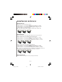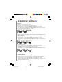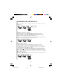
1
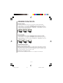
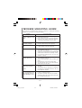
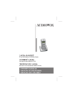
2.4GHz Digital Spread Spectrum
Dual Handset Cordless Phone
Téléphone numérique sans fil 2.4GHz
à identification de l'appelant et haut-parleur
Teléfono inalámbrico con dos auriculares y
espectro digital de 2.4GHz
OWNER'S MANUAL
MANUEL D'UTILISATION
MANUAL DEL USUARIO
CONTENTS
IMPORTANT SAFETY INSTRUCTIONS ............................ 2-3
BATTERY CAUTIONARY INSTRUCTIONS .......................... 3
IMPORTANT ELECTRICAL CONSIDERATIONS ............... 4 - 6
• Telephone line problems • FCC Part 15 regulation • Customer information
• Applicable for coin or pay phone only
INTRODUCTION ............................................................. 7
INSTALLATION ........................................................... 8 - 9
• Line cord connection • AC power connection • Battery installation and
charging • Placing the battery • Low battery voltage warning • Install base
unit & additional handset in a location
LOCATION OF CONTROLS ............................................ 10
• Handset section • Base section • Accessories • Icon explanations
USING THE MENU SYSTEM ............................................. 11
TELEPHONE OPERATION ......................................... 12 - 13
• Answering an incoming call • Making a call • Transferring an external call
MEMORY OPERATION ..............................................14 -15
• Adding a new entry to memory • Editing a memory entry • Delete a
memory entry
CALLER ID OPERATION ........................................... 16 - 17
• Dial from call record • Save the call record to phonebook • Delete the
call record • Delete all call record
TELEPHONE SETTINGS ............................................ 18 - 20
• Ringer volume • Ringer melody • Receiver volume • Keypad • Setting
clock • Format setting (12 hour) • Daily alarm setting
WALKIE-TALKIE FUNCTION ...................................... 21 - 22
OTHER FUNCTION ........................................................ 23
• Dialing mode • Auto answer • Speaker phone mode
TROUBLE SHOOTING GUIDE ........................................ 24
E-1
9038_2_ib_e.p65
1
10/31/03, 12:20 PM
IMPORTANT SAFETY INSTRUCTIONS
Please take a few moments to read the following instructions for your safety and to
ensure that you get the maximum benefit from your product.
When using your telephone equipment, basic safety precautions should always be
followed to reduce the risk of fire, electric shock, and injury to persons, including the
following :
1)
Read and understand all instructions.
2)
Follow all warnings and instructions marked on the product.
3)
Unplug this product from the wall outlet before cleaning. Do not use liquid cleaners
or aerosol cleaners. Use a dry cloth for cleaning.
4)
Do not use this product near water, for example, near a bath tub, wash bowl, kitchen
sink, laundry tub, in a wet basement, or near a swimming pool.
5)
Do not place this product on an unstable cart, stand, or table. The telephone may
fall, causing serious damage to the telephone.
6)
Slots and openings on the sides and back of the base of the phone are provided for
ventilation. These openings must not be blocked or covered. The opening should
never be blocked by a built-in installation unless proper ventilation is provided.
7)
This product should be operated only from the type of power source indicated on the
marking label. If you are not sure of the type of power supply to your home, consult
your dealer or local power company.
8)
Do not allow anything to rest on the power cord. Do not locate this product where
the cord will be abused by persons walking on it.
9)
Do not overload wall outlets and extension cords as this can result in the risk of fire
or electric shock.
10) Never push objects of any kind into this product through phone base slots as they
may touch dangerous voltage points or short out parts that could result in a risk of
fire or electric shock. Never spill liquid of any kind on the product.
11) To reduce the risk of electric shock, do not disassemble this product. Take it to a
qualified service personnel when some service or repair work is required. Opening
or removing covers may expose you to dangerous voltages or other risks. Incorrect
reassembly can cause electric shock when the appliance is subsequently used.
12) Unplug this product from the wall outlet and refer servicing to qualified service
personnel under the following condition.
a) When the power supply cord plug is damaged of frayed.
b) If liquid has been spilled into the product.
c) If the product has been exposed to rain or water.
E-2
9038_2_ib_e.p65
2
10/31/03, 12:20 PM
IMPORTANT SAFETY INSTRUCTIONS
d) If the product does not operate normally by following the operating instructions.
Adjust only those controls that are covered by the operating instructions. Improper
adjustment of other controls may result in damage, and will often require
extensive work by a qualified technician to restore the product to normal
operation.
e) If the product has been dropped of the cabinet has been damaged.
f) If the product exhibits a distinct change in performance.
13) Do not use the telephone to report a gas leak in the vicinity of the leak.
14) Avoid using a telephone (other than a cordless type) during an electrical storm.
There may be a remote risk of electric shock from lightning.
+
USE ONLY WITH CLASSE 2 POWER SOURCE 7.5V DC 450mA
7.5V DC 150mA
+
!
(For Base)
(For Charger)
BATTERY CAUTIONARY INSTRUCTIONS
CAUTION
Risk of explosion if battery is replaced by an incorrect type.
Replace only with the same type recommended by the manufacturer.
Dispose of used batteries according to the manufacturer’s instructions.
1) Use only the following type and size battery : type no. SHIDA BATTERY CO. LTD.,
AP55AAAH3 NIMH 3.6V 550mAH.
2) Do not dispose of the battery pack in a fire. The cell may explode. Check with state
and local codes for possible special disposal instructions.
3) Do not open and mutilate the battery pack. Released electrolyte is corrosive and may
cause damaged to the eyes or skin. It may be toxic if swallowed.
4) Exercise care in handling the battery to prevent shorting it with conducting materials
such as rings, bracelets, and keys. The battery or conductor may overheat and cause
burns.
5) Charge the battery pack provided with or identified for use with this product only in
accordance with the instructions and limitations specified in the instruction manual
provided for this product.
6) Observe proper polarity orientation between the battery pack and battery charger.
7) Keep batteries out of the reach of children.
SAVE THESE INSTRUCTIONS
E-3
9038_2_ib_e.p65
3
10/31/03, 12:20 PM
IMPORTANT ELECTRICAL CONSIDERATIONS
Unplug all electrical appliances when you know an electrical storm is approaching.
Lighting an pass through your household wiring and damage any device connected to it.
This telephone is no exception.
Warning : Please do not attempt to unplug any appliance during an electrical storm.
Caution : Changes or modifications to this product not expressly approved,or operation
of this product in any way other than as detailed by this Operating Guide,
could void your authority to operate this product as well as void they product’s
warranty.
Telephone Line Problems
The FCC has granted the telephone company the right to disconnect service in the event
that your phone causes problems on the telephone line. Also, the telephone may make
changes in facilities and services which may effect the operation of your unit. However,
your telephone company must give adequate notice in writing prior to such actions to
allow you time for making necessary arrangements to continue uninterrupted service.
If you are having trouble with your telephone service, you must first disconnect your
phone to determine if it is the cause of your problem. If you trouble has been corrected.
FCC Part 15
Warning : Changes or modifications to this unit not expressly approved by the party
responsible for compliance could void the user's authority to operate the
equipment.
Caution : To maintain compliance with the FCC’s RF exposure guidelines place the
base unit at least 20 cm from nearby persons.
Note : This equipment has been tested and found to comply with the limits for a Class
B digital device, pursuant to Part 15 of the FCC Rules. These limits are designed to
provide reasonable protection against harmful interference in a residential installation. This equipment generates, uses and can radiate radio frequency energy and, if not
installed and used in accordance with the instructions, may cause harmful interference
to radio communications.
However, there is no guarantee that interference will not occur in a particular installation. If this equipment does cause harmful interference to radio or television reception which can be determined by turning the equipment off and on, the user is encouraged to try to correct the interference by one or more of the following measures.
Increase the separation between the equipment and receiver.
Connect the equipment into an outlet on a circuit different from that to which the
receiver is needed.
Consult the dealer or an experienced radio/TV technician for help.
Customer information
This equipment complies with Part 68 of the FCC rules and the requirements adopted by
the ACTA. On the bottom of this equipment is a label that contains, among other
information, a product identifier in the format US:3W4WI03BTL9035, if requested, this
number must be provided to the telephone company.
E-4
9038_2_ib_e.p65
4
10/31/03, 12:20 PM
IMPORTANT ELECTRICAL CONSIDERATIONS
An applicable certification jacks Universal Service Order Codes (USOC) for the equipment is provided
(i.e., RJ11C) in the packaging with each piece of approved terminal equipment.
A plug and jack used to connect this equipment to the premises wiring and telephone network must
comply with the applicable FCC Part 68 rules and requirements adopted by the ACTA. A compliant
telephone cord and modular plug is provided with this product. It is designed to be connected to a
compatible modular jack that is also compliant. See installation instructions for details.
The REN is used to determine the number of devices that may be connected to a telephone line. Excessive
RENs on a telephone line may result in the devices not ringing in response to an incoming call. In most
but not all areas, the sum of RENs should not exceed five (5.0). To be certain of the number of devices that
may be connected to a line, as determined by the total RENs, contact the local telephone company. [For
products approved after July 23, 2001, the REN for this product is part of the product identifier that has the
format US:3W4WI03BTL9035. The digits represented by ## are the REN without a decimal point (e.g.,
03 is a REN of 0.3). For earlier products, the REN is separately shown on the label.
If this equipment Model TL9038 causes harm to the telephone network, the telephone company will notify
you in advance that temporary discontinuance of service may be required. But if advance notice isn’t
practical, the telephone company will notify the customer as soon as possible. Also, you will be advised
of your right to file a complaint with the FCC if you believe it is necessary.
The telephone company may make changes in its facilities, equipment, operations or procedures that
could affect the operation of the equipment. If this happens the telephone company will provide advance
notice in order for you to make necessary modifications to maintain uninterrupted service.
Please follow instructions for repairing if any (e.g. battery replacement section); otherwise do not alternate or repair any parts of device except specified.
Connection to party line service is subject to state tariffs. Contact the state public utility commission,
public service commission or corporation commission for information.
The equipment is hearing aid compatible.
NOTICE: If your home has specially wired alarm equipment connected to the telephone line, ensure the
installation of this [equipment ID] does not disable your alarm equipment. If you have questions about
what will disable alarm equipment, consult your telephone company or a qualified installer.
Should you experience trouble with this equipment, please contact (Audiovox Electronics Corporation,
150 Marcus Blvd. Hauppauge, New York 11788. Phone: 1-800-252-6123) for repair or warranty information. If the equipment is causing harm to the telephone network, the telephone company may request
that you disconnect the equipment until the problem is resolved.
NOTICE: According to telephone company reports, AC electrical surges, typically resulting from lightning strikes, are very destructive to telephone equipment connected to AC power sources. To minimize
damage from these types of surges, a surge arrestor is recommended.
Applicable for Coin or Pay Phone Only
To comply with state tariffs, the telephone company must be given notification prior to connection for
customer-owned coin or credit card phone. In some states, the state public utility commission, public
service commission or corporation commission must give prior approval of connection.
E-5
9038_2_ib_e.p65
5
10/31/03, 12:20 PM
IMPORTANT ELECTRICAL CONSIDERATIONS
“This product meets the applicable Industry Canada technical specifications.”
Before installing this equipment, users should ensure that it is permissible to be connected to the facilities of the local telecommunications company. The equipment must
also be installed using an acceptable method of connection. In some cases, the
company’s inside wiring associated with a single line individual service may be extended by means of a certified connector assembly (telephone extension cord). The
customer should be aware that compliance with the above conditions may not prevent
degradation of service in some situations.
Repairs to certified equipment should be made by an authorized Canadian maintenance
facility designated by the supplier. Any repairs or alternations made by the user to this
equipment, or equipment malfunctions, may give the telecommunications company
cause to request the user to disconnect the equipment.
Users should ensure for their own protection that the electrical ground connections of
the power utility, telephone lines and internal metallic water pipe system, if present, are
connected together. This precaution may be particularly important in rural areas.
Caution: Users should not attempt to make such connections themselves, but should
contact the appropriate electric inspection authority, or electrician, as appropriate.
“The Ringer Equivalence Number is an indication of the maximum number of terminals
allowed to be connected to a telephone interface. The termination on an interface may
consist of any combination of devices subject only to the requirement that the sum of the
Ringer Equivalence Numbers of all the devices does not exceed five.”
E-6
9038_2_ib_e.p65
6
10/31/03, 12:20 PM
INTRODUCTION
TELEPHONE FEATURES
•
•
•
•
•
•
•
•
•
•
•
•
•
•
•
•
•
•
•
•
•
•
•
•
•
•
•
•
Operating in 2400 MHz ~ 2483 MHz.(ISM band) with 45 Channels
Digital Spread Spectrum Technology (Frequency Hopping)
Up to 4 Handsets operate in one base.
Caller ID with call waiting function (Type II).
Speaker phone function in handset.
60 hours Standby time, 6 hours talk time.
Simultaneous call – a Telephone call & 1 pair of Intercom call (HS 2 & HS3)
Two line Displaying Alphanumeric Characters (2 x 10-digit Dot Matrix LCD) &
functional Icons.
Auto talk (pick up the handset from cradle during call ringing)
Auto standby (place handset on cradle after call conversation)
Call transfer between H/S.
Clear talk Range – Min. 220meter outdoors (line on sight).
Up to 50 phone book memories; 20 digits with 10 characters.
10 dialed number records (20 digits).
7-level Adjustable Receiver Volume
7-level Adjustable Ringer Volume
10 Ringer melody selection
Name to number matching *
Real time clock function
Call timer display
Alarm clock function
Hold function for call transfer
Pre - dial facility.
Low battery indication.
Keypad Lock
Key tone on/off
Walkie-Talkie function
Speaker phone function.
* Function has to work with caller ID feature.
Important: In order to use Caller ID functions, you must subscribe to Caller ID service
from your local access provider. To receive calling number in your display while you are
on the phone, you must subscribe to caller ID and call waiting with your local telephone
provider.
NOTE : The two handsets supplied with this model are already registered with the
main base. All other additional handsets purchased will need to be subscribed to the
main base. (See instructions included with additional handsets for further details).
E-7
9038_2_ib_e.p65
7
10/31/03, 12:20 PM
INSTALLATION
LINE CORD CONNECTION :
Plug the telephone line cord into the modular jack on the back of the telephone base and
the other end into the modular jack of your telephone wall outlet.
AC POWER CONNECTION :
Use only the AC/DC adaptor provided with the telephone. First insert the DC adaptor
plug into the DC adaptor socket provided on the telephone base. Then plug the AC
adaptor into your main power outlet.
BATTERY INSTALLATION AND CHARGING :
This equipment uses Nickel Metal Hydride (NiMH) batteries. To keep the batteries at
full charge you can leave the handset in the base unit at all times for safe trickle
charging. During charge, the charge LED will be on and battery icons will be FLASHING.
PLACING THE BATTERY
Place the battery pack as shown below. Observing correct polarity.
LOW BATTERY VOLTAGE WARNING
At installation the battery voltage will be low and the handset should be placed on the
station for 10 hours continuously to fully charge the batteries.
If the voltage is extremely low then the handset will not function at all, but if there is
sufficient residual voltage then the handset will power up indicating low voltage. This
can be seen from both the battery icon flashing empty.
E-8
9038_2_ib_e.p65
8
10/31/03, 12:20 PM
INSTALLATION
Install base unit & additional handset in a location where:
- Away from electrical appliances, such as computer, TV, microwave ovens, wireless
equipment or another cordless phone.
- In a HIGH and CENTRAL location with no obstructions & barriers,
- For maximum reception & noise free during use the phone, keeping handset as close
to the base unit.
- Being visible at most of your area.
E-9
9038_2_ib_e.p65
9
10/31/03, 12:20 PM
LOCATION OF CONTROLS
HANDSET SECTION
BASE SECTION
1)
2)
3)
4)
5)
6)
7)
8)
9)
10)
11)
12)
13)
16)
17)
18)
19)
RECEIVER
DISPLAY
OFF HOOK / YES / FLASH KEY
INT / REDIAL / PAUSE KEY
ON HOOK / NO KEY
SCROLL KEYS 5/6
DIAL KEYS / ID#’s
SPEAKER KEY
MICROPHONE
STRAP HOLDER
SPEAKER
BATTERY DOOR
HEADSET JACK
PAGE KEY
IN- USE & CHARGER LED
LINE CORD MODULAR JACK
ADAPTOR SOCKET
16
18
17
19
ACCESSORIES
20)
21)
22)
23)
12
MAIN ADAPTOR
CHARGER ADAPTOR
LINE CORD
BATTERY PACK
20
21
CHARGER SECTION
14) CHARGE LED
15) ADAPTOR SOCKET
22
23
15
14
ICON EXPLANATIONS
RECEIVED SIGNAL STRENGTH INDICATOR (RSSI) :
On when registered and in range, flashes when out of range.
RINGER MUTED :
On when ringer volume is set to zero.
LINE INDICATOR :
On when the handset is on line.
BATTERY STRENGTH :
Three segments to indicate state of charge of battery. Flashes when battery
needs recharging.
E - 10
9038_2_ib_e.p65
10
10/31/03, 12:20 PM
USING THE MENU SYSTEM
The user interface has been designed with simplicity of operation in mind. Functions that
are not available from the keyboard directly are found within a shallow menu structure.
The menu is available from the default screen simply by pressing either of the 5/6(6)
arrow keys. All menus wrap around, for example if one presses down from the bottom
item one reaches the top item.
If the user has entered into the menu structure and decides not to complete the operation
that has been selected, then there are two mechanisms that allow the user to recover:
1. Pressing and holding the NO (5) key during a function will return the user to the menu
from which that function was selected. If this key is pressed while in a submenu then
the user is returned to the menu from which that submenu was selected.
2. Menus and memory selections (also navigated via the arrow keys) all have simple
timeouts, so that a phone left in these states will revert to the default screen after a
suitable period.
E - 11
9038_2_ib_e.p65
11
10/31/03, 12:20 PM
TELEPHONE OPERATION
ANSWERING AN INCOMING CALL
Internal call
When the internal call comes ,the display shows the identity (ID) number of the
calling handset. The user answers the call by pressing YES (3) and ends the call by
pressing NO (5).
Pressing NO (5) during ringing rejects the incoming call and both calling and called
handsets return to standby state.
External call
When an external call comes, the display will show the caller’s number and time. If the
handset is on charge unit (i.e. on base station), simply picking up the unit will cause it
to answer. If it is not, then press YES (3) to answer or press NO (5) to stop the ring.
“UNKNOWN” would be displayed during an incoming call if Caller ID service is not
activated, or if a network does not pass on this information, or if callers withhold their
numbers.
MAKING A CALL
Calling an External Number
In this case, the user goes off hook’ using the YES (3) key, then dials the number in the
standard way.
Once the user has chosen to go off-hook, the phone has no way of sensing that the
dialing of the number is finished. Therefore the display will revert to showing the
elapsed call duration after a 5-second timeout.
Pre-dialing
Here the user enters the number and can edit and correct it before going ‘off hook’, at
which point the number is actually dialed.
Calling from Alphanumeric Memory
The user dials a number, which has already been stored in one of the alphanumeric
memories. Entries in the memories are stored in alphabetical order, or in the case where
two memories have the same alpha name, they will be stored in the numeric order.
If a number exceeds 10 digits, the first 10 digits are shown initially.
As with other lists and menus, the memory lists will wrap around.
Calling another Internal Handset
Press and hold INT (REDAIL/PAUSE) (4) button for 1 second to activate an internal call
to call another handset that is registered on the same base. The display will show “INT?”
enter the hand set to call by dialing 1–4.
If the called handset is not subscribed (number has not been allocated), does not respond
or the handset is busy, the user will be given a “busy tone”.
Press NO (5) to end the call.
E - 12
9038_2_ib_e.p65
12
10/31/03, 12:20 PM
TELEPHONE OPERATION
Last Number Redial
In the on hook mode, press the REDIAL (INT/PAUSE) (4) button to show the last dialing
number on display.
The user can select up to last ten external numbers by pressing the 5/6(6) buttons.
These are stored in chronological order, with the most recent being displayed first. Then
press the YES (3) button to dial the selected number.
If there are no numbers in the list, then the redial button will show “NO ENTRIES”.
As with other lists and menus, the redial list will wrap around.
TRANSFERRING AN EXTERNAL CALL
It is not possible to transfer internal calls from one internal extension to another - the
users must redial. The facility to transfer an external call is described here.
Transferring to another registered handset
If the user needs to transfer an outgoing or incoming call to another handset registered
to the same base station, this is done by pressing the INT (REDIAL/PAUSE) (4) key for 1
second, followed by the internal telephone number. The call transfer is completed by
pressing the NO (5) key to return to standby state or aborted by pressing the INT
(REDIAL/PAUSE) (4) key for 1 second again. The call duration timer is not transferred
between internal extensions.
Transferring using the Flash Key
If the base station is connected to a PABX extension, then the OFF HOOK/YES (3) key
may be pressed during a call to send a Flash to the PABX. Call transfer to another PABX
extension is then handled according to the procedure specified by the PABX.
E - 13
9038_2_ib_e.p65
13
10/31/03, 12:20 PM
MEMORY OPERATION
This describes how memory is managed - how numbers are added, removed and edited.
All of these memory functions use the menu system.
ADDING A NEW ENTRY TO MEMORY
• Enter the Phonebook mode by pressing scroll keys 5/6(6), then press YES (3).
• Select the “STORE” then enter the Name and Number respectively.
• Press the YES (3) to confirm the corresponding input item.
Particular points to note are:
• Alpha characters are entered by pressing the number keys, which cycle round the
available characters. For example, pressing the 2 key once shows ‘A’, pressing it
again changes the character to ‘B’, pressing it again gives ‘C’, pressing it again gives
‘2’, then ‘A’ again etc. The user interface waits at each letter position until a key is
pressed, then stays there until no key is pressed for 3 seconds, at which point it moves
on to the next letter position. The user can correct entries using the 5(6) key.
• Pauses in the dialling sequence may be programmed as part of the number by pressing
the Pause (REDIAL/INT) (4) key during the number sequence.
• Holding down the NO (5) key at any point allows the user to abort the procedure.
EDITING A MEMORY ENTRY
Both the alpha name field and the phone number field of a memory entry can be edited.
This allows the user to change entries whose names have been misspelled or when their
contacts move house.
• Select to the “PHONE BOOK” by pressing scroll keys 5/6(6), then press YES (3).
• Select “EDIT” by pressing scroll keys 5/6(6) then press YES (3).
• Press scroll keys 5/6(6) to select the memory item that user need to edit
• Press YES (3) start the editing. (Name then number).
E - 14
9038_2_ib_e.p65
14
10/31/03, 12:20 PM
MEMORY OPERATION
DELETING A MEMORY ENTRY
Memory deletion is considerably simpler than adding new memory entries.
• Enter Phonebook mode by pressing scroll keys 5/6(6) and YES (3).
• Then select “DELETE” by pressing scroll keys 5/6(6) and YES (3).
• Press scroll keys 5/6(6) to select the memory to be deleted from the Phonebook.
• Press YES (3) to confirm the selection. “SURE?” would be shown on.
• Press YES (3) to execute the deletion.
E - 15
9038_2_ib_e.p65
15
10/31/03, 12:20 PM
CALLER ID OPERATION
These calls can also be dialed out and stored into the phone book.
Remark: To use the caller-ID operation, you have to subscribe the caller-ID service from
your operator.
DIAL FROM CALL RECORD
• Press scroll keys 5/6(6) to select “CLI RECORD”, then YES (3) to confirm.
• Press scroll keys 5/6(6) to select “VIEW” then YES (3) to confirm.
• Press scroll keys 5/6(6) to select the record to be dialed then YES (3) to dial it out.
SAVE THE CALL RECORD TO PHONE BOOK
•
•
•
•
Press scroll keys 5/6(6) to select “CLI RECORD”, then YES (3) to confirm.
Press scroll keys 5/6(6) to select “STORE PBK”, then YES (3).
Press scroll keys 5/6(6) to select the record to be stored then YES (3) to store it.
Enter the name then confirm by YES (3).
DELETE ONE CALL RECORDS
• Press scroll keys 5/6(6) to select “CLI RECORD”, then YES (3) to confirm.
• Press scroll keys 5/6(6) to select “DELETE ONE”, then YES (3).
• Press scroll keys 5/6(6) to select the call record to be deleted then YES (3) to confirm.
• Display will show “SURE?” to confirm the deletion.
• Press YES (3) again to execute the deletion.
E - 16
9038_2_ib_e.p65
16
10/31/03, 12:20 PM
CALLER ID OPERATION
DELETE ALL CALL RECORDS
•
•
•
•
Press scroll keys 5/6(6) to select “CLI RECORD”, then YES (3) to confirm.
Press scroll keys 5/6(6) to select “DELETE ALL”, then YES (3).
Display will show “SURE?” to confirm the deletion.
Press YES (3) again to execute the deletion.
CALLER-ID WITH CALL WAITING
During phone conversation, when there is incoming call from a third party, you will hear
beep tone from the handset receiver and the display will show the telephone number of
the third party.
• Simply press YES (3) to switch the line to the third party.
• Press YES (3) again if you want to switch the line back to the original party.
E - 17
9038_2_ib_e.p65
17
10/31/03, 12:20 PM
TELEPHONE SETTINGS
RINGER VOLUME
Ringer volume is set by following procedure.
• Press scroll keys 5/6(6) to select “RINGER” and press YES (3) to confirm.
• Press scroll keys 5/6(6) to select “VOLUME” and press YES (3) to confirm.
• Press scroll keys 5/6(6) to select Volume level (RING * to RING ******)
• Then press YES (3) to confirm the setting.
Note : The ringer volume setting is applied to internal calls, external calls.
RINGER MELODY
The user will be able to choose the ringer melody from a list of pre-set tones.
Set the ringer melody for external call (Incoming call)
• Press scroll keys 5/6(6) to select “RINGER” and press YES (3) to confirm.
• Press scroll keys 5/6(6) to select “EXTERNAL” and press YES (3) to confirm.
• Press scroll keys 5/6(6) to select RING NUMBER and press YES (3) to confirm.
Set the ringer melody for Internal call (Intercom)
• Press scroll keys 5/6(6) to select “RINGER” and press YES (3) to confirm.
• Press scroll keys 5/6(6) to select “INTERNAL” and press YES (3) to confirm.
• Press scroll keys 5/6(6) to select RING NUMBER and press YES (3) to confirm.
Note : When one of the melodies has been selected, the corresponding melody will
sound. However, this melody would not be set until YES (3) is pressed.
RECEIVER VOLUME
Receiver volume is set using the scroll keys during the talk mode.
E - 18
9038_2_ib_e.p65
18
10/31/03, 12:20 PM
TELEPHONE SETTINGS
KEYPAD
There are two user options for the keypad,
The keypad can be locked to prevent unintended operation
• Press scroll keys 5/6(6) to select “KEYPAD” and press YES (3) to confirm.
• Press scroll keys 5/6(6) to select “KEY LOCK” and press YES (3) to lock the key pad.
Once locked, all key presses cause the message ‘UNLOCK?’ to be shown on the LCD.
The user must then press the YES (3) key to unlock.
The Key tone can be used to indicate that a key has been pressed. This beep can be
enabled or disabled.
To disable the key tone:
• Press scroll keys 5/6(6) to select “KEYPAD” and press YES (3) to confirm.
• “KEY TONE” would be displayed and press YES (3) to confirm.
• Press scroll keys 5/6(6) to select “TONE OFF” and press YES (3) to disable the key
tone.
To enable the key tone:
• Press scroll keys 5/6(6) to select “KEYPAD” and press YES (3) to confirm.
• “KEY TONE” would be displayed and press YES (3) to confirm.
• Press scroll keys 5/6(6) to select “TONE ON” and press YES (3) to enable the key tone.
SETTING CLOCK
The clock is set by the user and can be viewed as 24 hour or 12 hour. The default format
is factory set, but the user can then change to the alternative format if preferred.
• Press scroll keys 5/6(6) to select “CLOCK” and press YES (3) to confirm.
• Press scroll keys 5/6(6) to select SET TIME and press YES (3) to confirm.
• “TIME” is displayed, key in the correct time by 24 hour format. (e.g. 10:00pm, press
2200 ) then YES (3) to confirm.
• The set time is displayed on LCD.
E - 19
9038_2_ib_e.p65
19
10/31/03, 12:20 PM
TELEPHONE SETTINGS
Note that if Caller ID service is activated, this service will reset the time at every
incoming call.
FORMAT SETTING (12 HOUR)
• Press scroll keys 5/6(6) to select “CLOCK” and press YES (3) to confirm.
• Press scroll keys 5/6(6) to select “SET FORMAT” and press YES (3) to confirm.
• Press scroll keys 5/6(6) to select “12 - HOUR” and press YES (3) to confirm.
• The clock will be displayed by set format (e.g. 10:00A)
For the 24 hours setting, it is same procedure as above except selecting 24 HOUR at item
3. The clock will be displayed by 24 hour format (e.g. 22:00).
DAILY ALARM SETTING
• Press scroll keys 5/6(6) to select “CLOCK” and press YES (3) to confirm.
• Press scroll keys 5/6(6) to select “SET ALARM” and press YES (3) to confirm.
• “TIME? hh:mm” is displayed, key in the desired alarm time in 24 hour format. (e.g.
10:00pm, press 2200 ) then YES (3) to confirm.
• Press scroll keys 5/6(6) to turn on the ALARM ON and press YES (3) to confirm.
• A clock icon “ “ will be displayed beside the real time clock when the alarm is set.
Note : When the alarm is ringing, it can only be stopped with the YES (3) key. The YES (3)
key only turns off the alarm for that day, it will ring each day at the set time until “ALARM
OFF” is selected as above.
During phone conversation, the alarm tone will only be heard from the handset receiver.
You can press YES (3) to stop it.
E - 20
9038_2_ib_e.p65
20
10/31/03, 12:20 PM
WALKIE-TALKIE FUNCTION
Handset could be set to walkie-talkie mode. In walkie-talkie mode, handset could
communicate with other handset even the base is unavailable.
ENABLE WALKIE-TALKIE MODE
- By manual
• Press scroll keys 6/5(6) to select “W-TALKIE” and press YES (3) to confirm.
• Press 6/5(6) to select walkie-talkie mode on or off (e.g. “MODE ON ) and press
YES (3) to comfirm.
• Press scroll keys 6/5(6) to assign walkie-talkie ID number.
• Press YES (3) to confirm the setting and handset will enter to walkie-talkie mode.
Note : For each handset, a different ID# must be assigned, for example: if you have 2
handsets, the first one should be set to W-T ID1 and the second handset should be set
to W-T ID2 & so on for the additiont of more handsets.
- By short-cut key (For Twins Handsets version only)
• Press and hold ‘
* ‘ key for 1 second in standby mode.
DISABLE WALKIE-TALKIE MODE (BACK TO PHONE MODE)
- By manual
• Press scroll keys 6/5(6) to select “W-TALKIE” and press YES (3) to confirm.
• Press 6/5(6) to select walkie-talkie mode on or off (e.g. “MODE OFF ).
• Press YES (3) to confirm the setting and handset will go back to phone mode.
- By short-cut key (For Twins Handsets version only)
• Press and hold ‘
* ‘ key for 1 second in walkie-talkie mode.
MAKE WALKIE-TALKIE CALL.
• Press the dial keys (7) to enter the ID# for the handset you want to call, then press
YES (3) to call.
• A calling tone could be heard if it is available and within the communication range.
• Press the NO (5) key to end the call.
E - 21
9038_2_ib_e.p65
21
10/31/03, 12:20 PM
WALKIE-TALKIE FUNCTION
ANSWER WALKIE-TALKIE CALL.
• Press YES (3) to answer the call.
Both handsets have to be set to walkie-talkie mode before talking walkie-talkie call.
In walkie-talkie mode, handset could not make & response phone/intercom call.
Note :
Please check battery level in handsets before taking them away for Walkie Talkie
function.
In standby mode, handset’s battery will be consumed very soon IF its base is not
available. Therefore, you are recommended that:
• Unplug batteries from your handsets before taking them away from their Base.
• Connect the batteries back to handsets and switch handsets to Walkie Talkie mode
when you want to use Walkie Talkie function.
or
• Switch your handsets to walkie talkie mode before its Base will be unavailable.
E - 22
9038_2_ib_e.p65
22
10/31/03, 12:20 PM
OTHER FUNCTION
DIALING MODE
The dialing mode (DTMF/ Pulse) in base is decided by handsets independently.
• Press scroll keys 5/6(6) to select “ADVANCED”, then press YES (3) to confirm.
• Press scroll keys 5/6(6) again to select “DIAL MODE”, then press YES (3) to confirm.
• Press scroll keys 5/6(6) to select either “TONE DIAL” or “PULSE DIAL”, then press
YES (3) to confirm the dialing mode.
AUTO ANSWER
The auto answer function could be activated/deactivated by following procedure.
• Press scroll keys 5/6(6) to select “ADVANCED”, then press YES (3) to confirm.
• Press scroll keys 5/6(6) again to select “AUTO ANS”, then press YES (3) to confirm.
• Press scroll keys 5/6(6) to select either “AUTO ON” or “AUTO OFF”, then press
YES (3) to confirm.
SPEAKER PHONE MODE
Enable the speakerphone mode:
While the phone is in off hook mode or in Walkie Talkie mode (handset to handset),
simply press and hold the speaker phone button X))), which is located at # key, for 1 sec
to activate the speaker phone mode. When speakerphone mode is activated, speaker
will sound and symbol “X“ will also show on LCD.
Disable the speakerphone mode.
Press and hold the speakerphone button for 1 sec. Speaker will be turned off.
E - 23
9038_2_ib_e.p65
23
10/31/03, 12:20 PM
TROUBLE SHOOTING GUIDE
In the event of your telephone NOT working or difficulty in opening, the following
suggestion can be help you of solving the problem.
Symptom
Suggested Solution
Base unit doesn't work
(Power "LED" does not
light)
• Ensure the power adaptor is firmly plugged into
power outlet & base unit.
• If power LED on base unit is still NOT lighted up,
make sure the power outlet has power by
connecting another appliance to the outlet.
Base LED doesn’t light up
for battery charging
• Ensure the charging contacts on the handset and
the base cradle are kept clean regularly.
Handset does NOT work at
all
• Ensure the handset battery is correctly connected
& fully charged up 10 hours before use.
No dial tone
• Ensure telephone line is plugged firmly into base
unit & telephone wall jack.
• Make sure your telephone line is operating
normally by unplugging the unit & replacing with
another which is known to be operating correctly.
• If you still don't hear dial tone, call your local
telephone company.
Receiving a call but
handset doesn't ring
• Ensure telephone line is plugged firmly into base
unit & telephone wall jack.
• Make sure handset battery is NOT in battery low
status.
• Handset may be out of range from the base.
• Try disconnecting some of your other extension
phones which you may have.
Interference by other calls
while using your phone
• Replace handset to base's cradle & try your phone
call later.
• This problem may be caused by your telephone
line wiring or local telephone services, call your
local telephone company.
If still
• Probably the phone is out of range, move closer
to base, or relocate the base.
• The phone operating range may be limited or
interfered by the layout of your home environment,
try to relocate the base unit.
Voice background, most of
time inherent with noise,
static OR fading in & out
E - 24
9038_2_ib_e.p65
24
10/31/03, 12:20 PM
9038_2_ib_e.p65
90 DAY LIMITED WARRANTY
AUDIOVOX ELECTRONICS CORPORATION (the Company) warrants to the original retail purchaser of this product that should this product or any part
thereof, under normal use and conditions, be proven defective in material or workmanship within 90 days from the date of original purchase, such defect(s)
will be repaired or replaced with new or reconditioned product (at the Company’s option) without charge for parts and repair labor.
To obtain repair or replacement within the terms of this Warranty, the product is to be delivered with proof of warranty coverage (e.g. dated bill of sale),
specification of defect(s), transportation prepaid, to an approved warranty station. For the location of the nearest warranty station to you, call toll-free to our
control office:
25
1-800-252-6123
This Warranty does not extend to the elimination of externally generated static or noise, to correction of antenna problems, to cost incurred for installation,
removal, or reinstallation of the product, or damage to tapes, compact discs, speakers, accessories or electrical systems.
E - 25
This Warranty does not apply to any product or part thereof which, in the opinion of the Company, has suffered or been damaged through alteration, improper
installation, mishanding, misuse, neglect, accident or by removal or defacement of the factory serial number/bar code label(s). THE EXTENT OF THE
COMPANY’S LIABILITY UNDER THIS WARRANTY IS LIMITED TO THE REPAIR OR REPLACEMENT PROVIDED ABOVE AND, IN NO EVENT, SHALL
THE COMPANY’S LIABILITY EXCEED THE PURCHASE PRICE PAID BY PURCHASER FOR THE PRODUCT.
The Warranty is in lieu of all other express warranties or liabilities. ANY IMPLIED WARRANTIES, INCLUDING ANY IMPLIED WARRANTY OF
MERCHANTABILITY, SHALL BE LIMITED TO THE DURATION OF THIS WRITTEN WARRANTY. ANY ACTION FOR BREACH OF ANY WARRANTY
HEREUNDER INCLUDING ANY IMPLIED WARRANTY OF MERCHANTABILITY MUST BE BROUGHT WITHIN A PERIOD OF 30 MONTHS FROM
DATE OF ORIGINAL PURCHASE. IN NO CASE SHALL THE COMPANY BE LIABLE FOR ANY CONSEQUENTIAL OR INCIDENTAL DAMAGES FOR
BREACH OF THIS OR ANY OTHER WARRANTY, EXPRESS OR IMPLIED, WHATSOEVER. No person or representative is authorized to assume for the
Company any liability other than expressed herein in connection with the sale of this product.
10/31/03, 12:20 PM
Some states do not allow limitations on how long an implied warranty lasts or the exclusion or limitation of incidental or consequential damage so the
above limitations or exclusions may not apply to you. This warranty give you specific legal rights and you may also have other rights which vary from
state to state.
U.S.A.: AUDIOVOX ELECTRONIC CORPORATION, HAUPPAUGE, NEW YORK 11788
CANADA: AUDIOVOX CANADA LTD., MISSISSAUGA, ONTARIO
AUSTRALIA: AUDIOVOX PACIFIC PTY LTD., DOYLE AVENUE, UNANDERRA, NEW 2526 • (042) 718-555
NEW ZEALAND: AUDIOVOX PACIFIC PTY LTD., UNIT B, 6 HEADERSON PLACE, PENROSE, AUCKLAND, AUCKLAND • (09) 645-720
Document Number 128-6930
From No. 128-4648