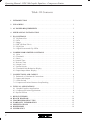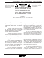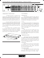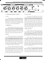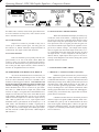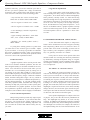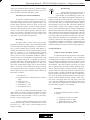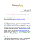
1
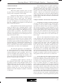
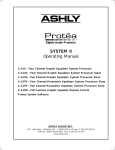
DPX-100 Graphic Equalizer Compressor/Limiter Operating Manual 25 Model DPX-100 Graphic Equalizer Compressor/Limiter 40 63 100 180 250 400 630 1K 1.8K 2.5K 4K Gain 16K 6.3K 10K +6 +4 +2 0 -3 -9 +15 +10 +5 0 -5 -10 -15 -∞ dB Th. 2 Range ±6dB ±15dB HPF -3 In Out -10 -15 -6 +3 +6 -6 EQ Sig Clip 20Hz Out 0 +10 dB +15 Gain -10 -3 4 Clip Input/Output Level (dB) -18 -15 -12 -9 -6 -3 0 +3 +6 +9 +20 Gain Reduction (dB) 6 8 10 12 14 16 18 20 0 +3 5 7 +6 3 +10 +20 2.5 -40 dB +22 2 10 -20 Threshold ∞ Ratio 2 3 1.5 20 1 30 .5 .5 5 10 .2 mS 15 20 Attack .2 -3 -6 -10 1 2 .1 Sec 3 Release 0 +3 Output Input +6 +10 +15 -20 - ∞ dB +20 Output Level In Power ASHLY AUDIO INC. 847 Holt Road Webster, NY 14580-9103 Phone: (585) 872-0010 Toll-Free: (800) 828-6308 Fax: (585) 872-0739 Internet: www.ashly.com Operating Manual - DPX-100 Graphic Equalizer - Compressor/Limiter Table Of Contents 2 1 INTRODUCTION . . . . . . . . . . . . . . . . . . . . . . . . . . . . . . . . . . . . . . . . . . . . . . . . . . . . . . . 3 2 UNPACKING . . . . . . . . . . . . . . . . . . . . . . . . . . . . . . . . . . . . . . . . . . . . . . . . . . . . . . . . . . . . 3 3 AC POWER REQUIREMENTS . . . . . . . . . . . . . . . . . . . . . . . . . . . . . . . . . . . . . . . . . . . 3 4 MECHANICAL INSTALLATION . . . . . . . . . . . . . . . . . . . . . . . . . . . . . . . . . . . . . . . . . 4 5 EQ 5.1 5.2 5.3 5.4 5.5 5.6 CONTROLS . . . . . . . . . . . . . . . . . . . . . . . . . . . . . . . . . . . . . . . . . . . . . . . . . . . . . . . . . EQ Boost/Cut . . . . . . . . . . . . . . . . . . . . . . . . . . . . . . . . . . . . . . . . . . . . . . . . . . . . . . . . Gain . . . . . . . . . . . . . . . . . . . . . . . . . . . . . . . . . . . . . . . . . . . . . . . . . . . . . . . . . . . . . . . . Range . . . . . . . . . . . . . . . . . . . . . . . . . . . . . . . . . . . . . . . . . . . . . . . . . . . . . . . . . . . . . . . HPF (Hi-Pass Filter) . . . . . . . . . . . . . . . . . . . . . . . . . . . . . . . . . . . . . . . . . . . . . . . . . . EQ In/Out . . . . . . . . . . . . . . . . . . . . . . . . . . . . . . . . . . . . . . . . . . . . . . . . . . . . . . . . . . . Signal Present and Clip LEDs . . . . . . . . . . . . . . . . . . . . . . . . . . . . . . . . . . . . . . . . . . 4 4 4 4 4 4 4 6 COMPRESSOR/LIMITER CONTROLS . . . . . . . . . . . . . . . . . . . . . . . . . . . . . . . . . . . 6.1 Gain . . . . . . . . . . . . . . . . . . . . . . . . . . . . . . . . . . . . . . . . . . . . . . . . . . . . . . . . . . . . . . . . 6.2 Threshold . . . . . . . . . . . . . . . . . . . . . . . . . . . . . . . . . . . . . . . . . . . . . . . . . . . . . . . . . . . . 6.3 Ratio . . . . . . . . . . . . . . . . . . . . . . . . . . . . . . . . . . . . . . . . . . . . . . . . . . . . . . . . . . . . . . . . 6.4 Attack Time . . . . . . . . . . . . . . . . . . . . . . . . . . . . . . . . . . . . . . . . . . . . . . . . . . . . . . . . . . 6.5 Release Time . . . . . . . . . . . . . . . . . . . . . . . . . . . . . . . . . . . . . . . . . . . . . . . . . . . . . . . . . 6.6 Output Level . . . . . . . . . . . . . . . . . . . . . . . . . . . . . . . . . . . . . . . . . . . . . . . . . . . . . . . . . 6.7 In/Out Switch . . . . . . . . . . . . . . . . . . . . . . . . . . . . . . . . . . . . . . . . . . . . . . . . . . . . . . . . 6.8 Threshold/Gain Reduction Display . . . . . . . . . . . . . . . . . . . . . . . . . . . . . . . . . . . . . 6.9 Input/Output Meter Display . . . . . . . . . . . . . . . . . . . . . . . . . . . . . . . . . . . . . . . . . . . . 5 5 5 5 5 5 6 6 6 6 7 CONNECTIONS AND CABLES . . . . . . . . . . . . . . . . . . . . . . . . . . . . . . . . . . . . . . . . . . 7.1 Balanced vs Unbalanced Connections . . . . . . . . . . . . . . . . . . . . . . . . . . . . . . . . . . . 7.2 Inputs and Outputs . . . . . . . . . . . . . . . . . . . . . . . . . . . . . . . . . . . . . . . . . . . . . . . . . . . . 7.3 Chain Switch . . . . . . . . . . . . . . . . . . . . . . . . . . . . . . . . . . . . . . . . . . . . . . . . . . . . . . . . 7.4 Compressor/Limiter Detector Loop/Ducking . . . . . . . . . . . . . . . . . . . . . . . . . . . . . 6 6 7 7 7 8 TYPICAL APPLICATIONS . . . . . . . . . . . . . . . . . . . . . . . . . . . . . . . . . . . . . . . . . . . . . . 8.1 Graphic Equalizer Applications . . . . . . . . . . . . . . . . . . . . . . . . . . . . . . . . . . . . . . . . 8.2 Compressor/Limiter Applications . . . . . . . . . . . . . . . . . . . . . . . . . . . . . . . . . . . . . . . 8.3 Special Effects . . . . . . . . . . . . . . . . . . . . . . . . . . . . . . . . . . . . . . . . . . . . . . . . . . . . . . . 7 7 8 9 9 10 11 12 13 14 15 DESIGN THEORY . . . . . . . . . . . . . . . . . . . . . . . . . . . . . . . . . . . . . . . . . . . . . . . . . . . . . . BLOCK DIAGRAM . . . . . . . . . . . . . . . . . . . . . . . . . . . . . . . . . . . . . . . . . . . . . . . . . . . . . TROUBLESHOOTING TIPS . . . . . . . . . . . . . . . . . . . . . . . . . . . . . . . . . . . . . . . . . . . . WARRANTY INFORMATION . . . . . . . . . . . . . . . . . . . . . . . . . . . . . . . . . . . . . . . . . . SPECIFICATIONS . . . . . . . . . . . . . . . . . . . . . . . . . . . . . . . . . . . . . . . . . . . . . . . . . . . . . DIMENSIONS . . . . . . . . . . . . . . . . . . . . . . . . . . . . . . . . . . . . . . . . . . . . . . . . . . . . . . . . . . SCHEMATICS 11 14 14 15 15 16 Operating Manual - DPX-100 Graphic Equalizer - Compressor/Limiter The lightning flash with arrowhead symbol, within an equilateral triangle, is intended to alert the user to the presence of uninsulated "dangerous volt age" within the product's enclosure that may be of sufficient magnitude to constitute a risk of electric shock to persons. CAUTION RISK OF ELECTRIC SHOCK DO NOT OPEN The exclamation point within an eqilateral triangle is intended to alert the user to the presence of import ant operating and maintenance instructions in the literature accompanying the device. TO REDUCE THE RISK OF ELECTRIC SHOCK, DO NOT REMOVE COVER. NO USER SERVICEABLE PARTS INSIDE. REFER SERVICING TO QUALIFIED SERVICE PERSONNEL. TO REDUCE THE RISK OF FIRE OR ELECTRICAL SHOCK, DO NOT EXPOSE THIS APPlIANCE TO RAIN OR MOISTURE. TO REDUCE THE RISK OF FIRE, REPLACE ONLY WITH SAME TYPE FUSE. REFER REPLACEMENT TO QUALIFIED SERVICE PERSONNEL. WARNING: THIS APPARATUS MUST BE EARTHED 1. INTRODUCTION 2. UNPACKING The Ashly DPX-100 combines a 15 band graphic equalizer and full function peak compressor/limiter in a single rack space product. Both equalizer and compressor/limiter can be used as stand-alone processors, or can be automatically chained together with a back panel switch. As a part of our system of quality control, every Ashly product is carefully inspected before leaving the factory to ensure flawless appearance. After unpacking, please inspect for any physical damage. Save the shipping carton and all packing materials , as they were carefully designed to reduce to minimum the possibility of transportation damage should the unit again require packing and shipping. In the event that damage has occurred, immediately notify your dealer so that a written claim to cover the damages can be initiated. The graphic equalizer section uses professional quality 25mm faders for maximum resolution and long life. Ashly graphic equalizers use "Q" enhanced Wein bridge filters with interleaved summing for constant "Q", low ripple, and minimum filter interaction. The Ashly compressor limiter circuit was designed in response to the need for universal peak-sensitive automatic gain control (AGC) devices with exceptional audio performance and rugged durability. The result is a wide-bandwidth, ultra-low-distortion, low noise VCA (voltage controlled amplifier) which is versatile and highly listenable. Premium components are used throughout the DPX-100, and computerized automatic assembly equipment verifies that each component's electrical specifications are within tight tolerances before becoming part of the circuit assembly. Each finished unit is then tested twice before leaving the factory, guaranteeing you a worry-free, professional product for many years. Please read this instruction manual thoroughly before operation so that you may realize all the features and benefits the Ashly DPX-100 has to offer. The right to any claim against a public carrier can be forfeited if the carrier is not notified promptly and if the shipping carton and packing materials are not available for inspection by the carrier. Save all packing materials until the claim has been settled. 3. AC POWER REQUIREMENTS A standard IEC-320 AC inlet is provided on the rear panel to accept the detachable power cord shipped with the unit. Units distributed within the United States are preselected for 120VAC, 60Hz and should be plugged into a standard NEMA 5-15 3-wire grounded AC receptacle. Most units distributed outside the US are preselected and labeled for 240VAC, 50-60Hz and are shipped with the appropriate power cord. The DPX-100 will perform normally from 95 to 125 volts AC. An internal line fuse is used. In the event of fuse failure, refer to a qualified service technician for servicing. Power consumption is less than 20 watts. 3 Operating Manual - DPX-100 Graphic Equalizer - Compressor/Limiter 25 40 63 1 00 1 80 2 50 4 00 6 30 1K 1 .8 K 2 .5 K 4K 1 6K 6 .3 K Gain 1 0K +1 5 +1 0 +5 0 M o del D PX -10 0 Graphic E q ualizer Com pres so r/L imiter -5 -1 0 +6 +4 +2 Range 0 -3 -9 HPF -∞ -1 5 dB ± 6 dB ±1 5d B S ig C lip 2 0 Hz O ut 4. MECHANICAL INSTALLATION 5. EQ CONTROLS The DPX-100 mounts in a standard 19 inch equipment rack. The mounting screw threads vary with different rack manufactures and you should refer to your rack instructions for proper hardware. An oval head or flat head screw with a plastic countersink washer is preferred to protect the finish of the DPX-100 under the screw. 5.1 EQ Boost/Cut The individual equalization faders adjust the boost or cut at each filter frequency. By adjusting a combination of faders, an overall frequency response can be developed and the physical position of the faders will give an approximate visual indication of this response. This unit is housed in a rugged steel case and will tolerate moderate abuse. However, for road systems which may be dropped or otherwise subjected to extreme forces, we recommend some rear support for the chassis to prevent bending the front panel the front panel when these forces occur. 5.2 Gain The gain control adjusts the overall gain of the equalizer when the EQ switch is “in”. It is generally used to compensate for level changes due to the equalization process, but can also allow the equalizer to adjust overall system level and gain structure. Overall gain with this control is from +6dB to -∞. For installations where it is desirable to protect the front panel controls from tampering or accidental misadjustment, use the Ashly security cover. Installation is simple and does not require removal of the equipment from your rack. See your Ashly dealer for details. 5.3 Range This switch selects the operating range of the individual equalization faders to either ±15dB or ±6dB. The ±15dB settings should be used when much equalization is needed. The ±6dB setting allows finer resolution on the fader settings. 5.4 HPF (Hi-Pass Filter) Ashly Security Cover Installation The high-pass filter can be used to supplement the frequency response achieved by the bandpass filters. It’s function is to “roll off” low end response to eliminate subsonic interference like wind noise, floor rumble, and boomy microphone pops. The high-pass frequency is fixed at 20Hz with an 18dB/octave slope. 5.5 EQ In/Out This switches out the boost/cut controls and EQ gain adjustments. This way, the effect of any equalization can be compared to a “flat” response. This switch does not defeat the high-pass filter. 5.6 Sig and Clip LEDs The signal present LED comes on when a signal greater than -20dBu arrives at the EQ input. The clip LED indicates any EQ signal level exceeding +19dBu. 4 EQ In O ut Operating Manual - DPX-100 Graphic Equalizer - Compressor/Limiter Th. 0 -3 -6 +3 +6 -6 -1 0 +1 0 -1 5 dB +1 5 Gain -1 0 -2 0 -4 0 2 -3 C lip Inpu t/ O utpu t L evel (dB ) -1 8 -1 5 -1 2 -9 -6 -3 0 +3 +6 +9 +20 G ain R e ductio n (d B) 6 8 10 12 14 16 18 20 4 0 +3 5 3 +6 +1 0 + 2 0 2 .5 2 dB +22 Threshold 7 10 ∞ Ratio 2 3 .5 5 1 .5 -6 10 20 1 3 0 .5 2 mS 20 Attack .1 S e c 3 Release +3 O utpu t Inpu t +6 -1 0 15 .2 0 -3 1 .2 -2 0 +1 0 - ∞ +1 5 dB +20 Output Level In Power 6. COMPRESSOR/LIMITER CONTROLS 6.4 ATTACK TIME 6.1 GAIN The response of the compressor/limiter to signal levels above threshold is further defined by the attack time control. Attack time is the amount of time it takes to attenuate the output level after threshold has been reached. For very fast transients, such as hand claps, snare drums, or other percussive sounds, a fast attack time is usually desirable so that the limiter can respond in time to control the peak level. On other types of program material, a slower attack time may be preferred. An abrupt attack may, on some material, “square off” the top of a waveform, producing a distorted sound. The DPX-100 provides continuously variable attack times from 200 microseconds to 20 milliseconds. The Gain control is used to adjust incoming signal level to the VCA circuit. It is always active, so switching out the limiter function has no effect on this control. Used in conjunction with the input/output level meter display, this control is useful for setting up optimal system levels. This control should normally be left at "0" to achieve accurate threshold calibration. 6.2 THRESHOLD The threshold control has a range of -40dB to +22 dB, allowing applications from low level compression to high level limiting. The threshold control determines the audio level above which gain reduction occurs. When the threshold LED comes on, that means that gain reduction is beginning to occur, due to input signal peaks exceeding the selected threshold in dB. 6.3 RATIO This control determines the resultant change in output level to changes in input level for all signals above threshold. The numbers printed around the ratio control are calibrated in db and indicate the increase in input (above threshold) required to produce a 1db increase in output. This can be expressed conveniently as a ratio. If the output remains constant no matter how high the input level, we have an infinite (∞) input/output ratio. It should be remembered that the ratio control has no effect on signals which are below threshold. There is a common but incorrect notion that limiting always implies the use of an infinite ratio. Although there are times when an infinite ratio is desirable, there will be situations where infinite, or “hard”, limiting action is neither appropriate nor necessary. In fact, it should be noted that an infinite ratio setting is likely to cause noticeable side effects in the sound, and may not be usable on programs where subtle control is desired. 6.5 RELEASE TIME Another parameter which affects compressor/limiter performance is release time, or the time required to restore system gain to normal after the input signal has fallen below threshold level. Again, proper release time will depend on the type of program material being processed and the way in which the limiter is being used. When subtle limiting is desired, slow release times are often chosen to avoid condition referred to as “pumping” or “breathing”. This occurs when overall gain is modulated up and down by repeated peaks which are followed by quieter intervals. If the release time is set too fast, then the overall level will jump up and down, producing an objectionable and unsettling effect. Note that, in some cases, an individual track or channel which seems to be pumping may sound acceptable when heard in context of a complete mix. A unique feature of Ashly Compressor/Limiters is the incorporation of a double release-time constant. When a conventional compressor/limiter is adjusted for slow release times, transients such as mic “pops” may cause a severe reduction in gain followed by a slow fadeup, making the action of the limiter very obvious. With 5 Operating Manual - DPX-100 Graphic Equalizer - Compressor/Limiter Comp INPUT S ar e Active B a la n c e d . O UTPUT S M a y B e Wir e d B a la n c e d O r Un ba la n c e d . AC Model DPX-100 Made In USA T IP = D e t e c (Use M R ING 3 2 1 X LR Fe m a le S h o wn CAUTION 1 00 -1 2 0VAC 5 0-60 Hz 1 2W R isk o f Elec tric S hock. D o Not Open the double time constant, release from gain reduction after a brief transient is always fast, with a slower release after a sustained overdrive. 6.6 OUTPUT LEVEL Output level control is provided to fully cut or restore up to 18 dB of system gain. For unity gain, set the control to 0. NOTE: When the compressor/limiter is switched out, the output control still functions. 6.7 IN/OUT SWITCH This switch enables you to quickly hear the compressor/limiter in or out of the audio chain. When the switch is in the out position, all limiting and compression controls and functions are bypassed, with the exception of the gain and output controls, which continue to function as straightforward level controls. (+) (-) Output 6.9 INPUT/OUTPUT METER SELECT While the Gain Reduction display accurately represents the action of the limiter, comparing input to output levels in real time is somewhat more intuitive, and is made simple using the input/output meter select switch. The input meter takes its signal just after the gain control, and will indicate input signal level regardless of output levels or limiter settings. The output meter display takes its signal from the actual output of the unit, so every control that affects the output will also have an effect on output meters. Used in conjunction with the gain reduction meters, input/output meters prove to be an extremely useful diagnostic tool when working with system dynamics and level control. 7. CONNECTIONS AND CABLES 6.8 THRESHOLD/GAIN REDUCTION DISPLAY 7.1 Balanced vs. Unbalanced Audio Connections As soon as the threshold level is reached, the yellow LED illuminates. Depending on how far the input level rises above threshold, successive red LED’s will illuminate, indicating gain reduction. Gain reduction can best be described as the difference between input level and the resulting change to output level. For signals below threshold, there will of course be no gain reduction, that is, a 10dB increase in input will yield a 10dB increase in output. For signals above threshold however, output level will increase only to the extent that the ratio control allows. With a high ratio, say 20 or so, it will take 20dB of increased input level to increase output level by 1dB. With a gentler ratio of 3:1, input signals above threshold will be “gain-reduced” at the output by 1/3. In other words, with threshold set at 0dB, a signal peak at +12 dBV that is 3:1 compressed (ratio at 3) will produce only +4 dB (12÷3) at the output, and 8 dB of gain reduction has occurred (12 dBV input minus 4 dBV output=8 dB reduction.) Balanced signal connections are preferred in pro audio applications because of their improved immunity to induced hum and noise. A properly shielded and wired balanced input stage on any audio product will reject most unwanted noise (RFI, EMI) picked up by the cable, as well as minimize ground loop problems. Therefore it is always advantageous to use balanced connections when running signal more than ten or fifteen feet, although particularly noisy environments may require that even short patch cables be balanced. 6 Unbalanced connections are used mostly for short distance, high level signals (0dBu nominal). Most external EMI noise pick-up will be masked under the noise floor of the signal, assuming there is little or no gain following the unbalanced signal. If a gain stage does follow a signal, or if externally sourced noise persists, use balanced connectors. Operating Manual - DPX-100 Graphic Equalizer - Compressor/Limiter mpressor/Limiter Graphic Equalizer PUSH PUSH t e c to r R e tu rn / D u ckin g In p u t Mono Plug For Ducking) ING = D e t e c to r S e n d Chain In O ut Input D e te ctor Output Input 7.2 Inputs and Outputs 7.3 Chain The DPX-100 uses two different audio connector types. 1/4" TRS (tip-ring-sleeve) phone jacks, and three pin XLR connectors will allow interfacing to most professional audio products. Ashly TRS balanced connections use the tip as (+) and the ring as (-) signal, with sleeve used for ground. Ashly XLR connectors use pin 2 (+) and pin 3 (-) with pin 1 ground. Inputs are 20KΩ active balanced using precision 1% metal film resistors, outputs are 200Ω "pseudo-balanced", which means they have balanced impedance with a single-ended signal source, and can be wired balanced or unbalanced. When possible, we recommend balanced connections between all components in your system. The chain button on the back panel allows the output of the equalizer to be fed directly to the input of the compressor/limiter, with no external cable required. When the chain switch is in, the input connectors to the compressor/limiter are removed from the circuit, while the graphic equalizer outputs remain functional. If inputs are used unbalanced, the signal should be on the (+) connection and the (-) connection must be tied to ground, or signal loss will result. While a mono phone plug used as an unbalanced connection will automatically ground the (-) ring of the jack, XLR's will not automatically do this, so attention must be given to proper wiring. Tip (+) R ing (-) S le e ve (G n d) S te re o Ph one Plu g u se d for bala nce d Tip (+) S le e ve (G n d) M ono Phon e Plug u se d for unbalan ce d X LR M ale X LR p ins are n um bere d on the con ne ctor inse rt. 2 = (+ ) 3 = (-) 1 = (g nd ) X LR Fe m a le 7.4 Detector Loop - Ducking The DPX-100 compressor/limiter has a TRS Insert DETECTOR PATCH point which can be used as a "ducking" input, or in conjunction with an equalizer to produce frequency-sensitive limiting. Various uses of the detector patch are discussed under TYPICAL APPLICATIONS. 8. TYPICAL APPLICATIONS By itself, the 15 band graphic EQ is useful for general tone control, feedback control, and room resonance correction. The compressor/limiter provides many solutions where dynamic signal level processing is required. The combination of graphic EQ and compressor/ limiter allows for additional applications, such as a full range speaker processor, 70 volt distributed system processor, mixing console channel insert, and frequency sensitive limiting, to name a few. In most cases, the DPX-100 should be the last device before the power amp or crossover, or right before a recording device or transmitter. 8.1 GRAPHIC EQUALIZER APPLICATIONS General Tone Control The graphic equalizer is a very useful device for general tone shaping because it is intuitive and easy to adjust. The visual reference provided by the slider position gives an approximate idea of the frequency response generated, with the lower frequencies on the left and higher frequencies on the right. To use the power of an Audio Connector Types 7 Operating Manual - DPX-100 Graphic Equalizer - Compressor/Limiter equalizer effectively, you need to translate your idea of the tone you want to produce into a range of numerical frequencies. This is simple after a little practise. Here are a few references which are useful for starting points: - Very low bass (the “wind” in a kick drum, almost felt as much as heard -40Hz-80Hz. - The low register of a male voice - 200Hz - The low register of a female voice - 350Hz - Lower midrange (“warmth” frequencies) 400Hz-1KHz Large Room Equalization Large rooms tend to suffer from multiple reflections with long time delays, long reverberation times, and “ring-modes”, all of which lead to reduced intelligibility and a generally “muddy” sound. As sound travels long distances through the air, high frequencies are attenuated more than low frequencies. In general, large rooms benefit from some low frequency roll-off, high frequency boost, and attenuation of ring mode frequencies. As in the case of feedback control, a graphic equalizer can help reduce an isolated ring-mode or two, but a tunable narrow-band equalizer such as a parametric is more effective here. - Upper midrange (“harshness”, snare drum “bite”, “hot” sound) -2.5KHz-4KHz. 8.2 COMPRESSOR/LIMITER APPLICATIONS - Sibilance (“sss” sounds, cymbal “sizzle”) 8KHz-15KHz. Try using these starting points as a guide when you want more or less of these types of sounds. Adjust by ear from there. It is always a good idea to remember that a little equalization usually works out much better than a lot, and that there are many audio problems which can not be solved with equalization alone. Feedback Control A graphic equalizer can be used to provide some control over moderate feedback problems, but does not have enough flexibility or resolution to handle severe situations. You will achieve the best results when you can eliminate one or two feedback points by setting one or two sliders for no more than a 6dB cut. Often you can find a feedback point by boosting sliders in succession to determine which frequency ranges contain the feedback modes, and then cutting those ranges. Be very careful in this process to avoid explosive feedback and possible system and hearing damage! If you find feedback points with many equalizer bands, remember that cutting every band may not help (all you will do is reduce system gain). The combination of a graphic equalizer for tone control and a parametric equalizer (such as the Ashly PQX-571 or PQX-572) for feedback control is highly recommended. As the functional name implies, a compressor/ limiter can be divided into two basic categories, limiting and compressing. When used as a protective device to prevent audio levels from overloading systems such as tape recorders, power amplifiers, speakers, or transmitters, it is generally referred to as a limiter. It may also be used to create special effects and unusual sounds for recording and musical performance by deliberately reducing the dynamic range of a signal, creating a much louder or fuller sounding signal without increasing the loudness peaks, in which case it is referred to as a compressor. The Limiter As A Protective Device The DPX-100 compressor/limiter section provides fast and accurate gain control for the prevention of sound system overload due to unexpected transients. Sound system distortion is usually the result of amplifiers running out of power, in which case nice round waveforms turn into harsh sounding squared-off waveforms. Looking at it from the perspective of the speaker diaphragm, this means that, whereas in normal operation the diaphragm is required to accelerate, slow down, smoothly change direction, and accelerate again, distorted operation requires an instant acceleration, instant stop, a change of direction, and instant acceleration again. Console Channel Equalization Many mixing consoles provide only simple equalization for individual channels. If your console has channel inserts, you can patch your graphic equalizer into a channel that’s being used for something important and use it to tailor the sound of this channel exactly the way you want. 8 Since speaker diaphragms are subject to the laws of physics, they won’t take this kind of punishment for long. The diaphragm may shatter, or its voice coil may overheat. In addition to the damaged caused by sustained overload, the speaker may also be damaged by occasional, one-shot high level overload, for example, the sound of a microphone falling face-first onto a hardwood floor. Even Operating Manual - DPX-100 Graphic Equalizer - Compressor/Limiter if this type of transient doesn’t destroy a speaker outright, it may damage the speaker surround in such a way as to cause mechanical abrasion and future failure. Alternatives For Sound Installations To install a compressor/limiter in a sound system using a passive crossover, insert it between your mixing console output and the power amplifier input. For systems using electronic crossovers, there are two ways to use a compressor/limiter. It may be inserted between the mixer output and the crossover input, in which case it will act on the entire audio frequency spectrum. Alternately, if the limiter is inserted between an output of the electric crossover and the input of a power amp, it will only affect a specific band of frequencies. Recording The Ashly limiter can be used to prevent tape saturation in analog recording. Also, with modern trends toward inexpensive digital recording, it remains necessary to protect against input overload. With digital recording, the information stored on tape, hard disk, optical disk, etc., is either a 1 or 0, so actual signal level on the tape is not the concern it is with analog recordings, in fact it is not even a user controllable parameter. What is of concern however, is the signal level applied to the A-D (analog to digital) converters. If clipping occurs at the converter input stage, the resulting distortion is most unpleasant, and will be recorded digitally as if they were part of the original audio signal, forever mixed with the audio. To prevent converter distortion while preserving the extended dynamic range of digital recording, look up the max input level of your recorder/converter and set up the limiter as follows: 1. Set Gain to 0. 2. Set Threshold to 2-3 dB below max converter input. 3. Set Ratio to 10. 4. Set Attack to 2 mS. 5. Set Release to .2 Sec. 6. Set Output level to 0. Broadcasting Compression has long been used as a tool to make an audio signal appear louder. A good example is in broadcasting, where competing stations with identical transmitters and power attempt to sound louder than each other. Since they are all restricted with respect to maximum audio level (modulation), their best tactic is to squeeze the dynamic range of their programs to just a few dB. The audio output level of the station virtually never changes, and the listener perceives this continuous high-level sound as being louder than the same material in an uncompressed form. Although both compressed and uncompressed programs reach the same peak levels, the compressed signal stays near peak level more of the time, and thus sounds louder. This technique makes the broadcast more intelligible over ambient noise, and increases the geographical area over which the broadcast is audible to the listener. Additionally, this compression technique is extremely useful for FM and infrared transmission systems for the hearing impaired. 8.3 Special Effects Compression For Feedback Control A common ritual in sound system set-up is equalizing the room to remove feedback. This is generally accomplished by turning up system gain to purposely induce feedback, searching for the center frequency of the feedback, and then equalizing at that frequency to remove the feedback. Once this frequency has been cut, system gain is again increased to induce another feedback point, and the whole procedure is repeated until the engineer is satisfied that the significant problem frequencies have been corrected. The major problem with this approach is that the feedback can easily get out control, and the engineer ends up dashing back and forth between the mixer volume controls and the equalizer controls, while everyone in the room plugs their ears and prays it will end soon. The Ashly DPX-100 can turn this procedure into a fast, painless job, eliminating loud feedback levels and the possibility of speaker or ear damage. Procedure: If you are exceeding threshold frequently, your input signal is probably too high and should be turned down. Of course, every situation is different, so experimentation before final recording is always a good idea, but this is a good starting point. To obtain a gentler limiting action at the expense of some dynamic range, decrease the threshold to -15 and the ratio to 3-5. This is also a good starting point for analog recording. 1. Set up the DPX-100 limiter controls as follows: a. b. c. d. Output level control to -20dB. Input Gain control to 0dB. Threshold control to -30dB. Ratio control to infinity (∞) 9 Operating Manual - DPX-100 Graphic Equalizer - Compressor/Limiter e. Attack time to 5mS. f. Release time to 1 Sec. g. Limit switch IN 2. Using a 1/3 octave (31 band) or parametric equalizer, set the EQ controls to a flat setting, and if the equalizer has an overall volume control, boost it by 10 to 15 dB. 3. Open up several microphone input channels to a normal operating level, with typical EQ settings, and turn the console master fader up to a louder than normal setting. At this point, the system should be well into feedback, but the room volume will be constant due to the action of the limiter. You can listen to the feedback at any level you like by simply varying the limiter output level control, although below a certain monitoring level, the feedback will stop. 4. Try to determine the feedback frequency, and then equalize it by adjusting the center frequency, bandwidth, and boost/cut controls of your parametric equalizer. (Note: a graphic equalizer can also be used, although with less accuracy.) After eliminating the problem frequency, try to further define it by sharpening up the bandwidth, reattacking the frequency control, and making the cut shallower, if possible. 5. As soon as the first feedback frequency has been removed, the compressor/limiter will automatically bring up system gain until another feedback point is induced. Repeat the equalization procedure until it becomes impossible to distinguish individual, predominant feedback frequencies. 6. Write down EQ marks for safekeeping if necessary, and return all mixer, EQ master gain, and compressor/limiter gain controls to normal operational settings. Altering the Texture of Musical Instruments It would be impossible to mention here all the ways that compression is used to create new sounds with familiar instruments. Some typical uses are: 1. Creating a “fatter” kick drum or snare sound. 2. “Thickening” acoustic guitars. 3. Adding punch and sustain to electric bass or guitar. In general, use a gentle compression ratio, say 4:1, with a 10 mS attack time, 0.1 Sec. release time, and a low enough threshold to cause 6 to 10dB of Gain Reduction. Try using this effect to help bring out a lead 10 vocal or instrumental solo in a cluttered mix. The compressor is also a great corrective tool when working with singers whose own dynamic control is less than perfect. A little compression helps to keep their quieter lines from becoming buried in the mix. Experimentation is highly recommended. Voice-Over Compression (“Ducking”) The compressor/limiter can be used to automatically reduce music to a background level when an announcer is speaking. In this scheme, only the music signal is actually gain-reduced by the limiter. However, the detector is connected to respond to an announcer’s voice instead of the music’s peaks. Voice-Over compression assumes you are already using some sort of mixer to combine the music and mic signals. Use the direct out (send) of the mic channel to feed the detector input on the CLX unit. Note: Be sure to use a mono plug for the CLX detector input. Then use the Threshold and Ratio controls to determine when and by how much the announcer’s voice affects the music level. De-Essing A special type of saturation problem often encountered in recording is the sibilant (Ssss) sound of the human voice. High frequency, sibilant sounds can reach very high energy levels, so that a voice that is otherwise undistorted breaks up on the esses, producing a raspy, undesirable sound. With analog recording to magnetic tape, high frequencies tend to saturate the tape sooner, and combined with the internal high frequency boost (record preemphasis) on standard tape decks, the need to control sibilants becomes apparent. The solution is frequency-dependent limiting, which is easily accomplished with the DPX-100. By inserting an equalizer into the Detector Patch point and boosting the equalizer at high frequencies in the vicinity of the sibilant, the limiter’s detector circuit becomes more sensitive to this particular range of frequencies, and so will limit the bothersome sibilants more than other frequencies. Realize that this technique is very different from simple equalization. Equalizing a sibilant vocal by cutting high frequencies would result in a loss of important high frequency information at all times, whereas de-essing has no effect whatsoever on the signal except at the instant of the sibilant. At that moment, the Ashly limiter will reduce overall gain. Frequency response is unaffected, and the sibilant is controlled. Operating Manual - DPX-100 Graphic Equalizer - Compressor/Limiter 9. DESIGN THEORY Graphic Equalizers: The Basics While most graphic equalizers look very much the same, there are several important differences in the circuitry used to implement various designs. Perhaps the major differences are in the filters. Some equalizers use a filter made of a capacitor, an inductor, and a resistor, or “RLC” filter. The advantage here is simplicity, but the real disadvantage is the inductor itself. An inductor is a coil of wire with a core of some sort. Inductors are susceptible to hum fields and they are large and expensive. Other equalizers use the same basic approach, but replace the inductor with a “simulated inductor”, which is actually a circuit comprised of an amplifier, a capacitor, and a couple of resistors. This adds parts but is less expensive than a real inductor. The problem with this approach is that simulation is less than ideal; it produces an inductor with high resistive loss resulting in poor curve shape when used in a filter. Another problem with “RLC” designs is that large capacitors must be used for the lower frequency filters, limiting the choice to large, expensive non-polar types or electrolytic capacitors with poor audio performance. Also, when this filter type is combined with a potentiometer to adjust the equalization, the resistance of this pot affects the “Q” of the filter so that a little equalization produces a much broader curve than a lot of equalization. The other filter approach is a true bandpass filter. This can be made with no inductors and more practical sized capacitors; the “Q” is easily set and remains constant, and the parts count is reasonable. there are several types of bandpass filters suitable for this job. Ashly uses a “Q” enhanced Wein-bridge filter. Because it is a symmetrical design using matched tuning components, the “Q” is easily set and is very stable. In designing a graphic equalizer, a selection of filter sharpness must be made. More sharpness (higher Q) produces less filter overlap and tighter control over an individual band, but also causes ripple in the frequency response when many filters are boost or cut together to produce a flat response. We feel that the graphic equalizer’s primary use is for “voicing” and tone control, and have set our filter sharpness to produce a maximum of 1dB ripple. The summing system in a graphic equalizer is also important. Since there are a number of filters which combine to produce the overall response, it is important that the filters not interact (they WILL overlap, but the response of one filter should not modify the response of another). Ashly uses an “interleaved” summing system where every other filter uses the same summing amplifier so that adjacent filters never share the same drive and feedback signals. This allows the filters to maintain their natural response. Compressor/Limiters: The Need For Gain Control The human ear excels in its ability to detect an extremely wide range of loudness levels, from the quietest whisper to roar of a jumbo jet. When we attempt to reproduce this dynamic range, by means of amplifiers, tape recorders, CD players, or radio transmitters, we run into one of the fundamental limitations of these electronic media: limited dynamic range. Amplifier dynamic range is quite good, and is adequate for most musical program material. However, some types of audio equipment, such as cassette tape recorders, have a very narrow useful dynamic range. What is it that compromises the dynamic range of this equipment? The useful operating region of a piece of audio equipment is squeezed in between noise and distortion. As program level decreases, it approaches what is known as the “noise floor”, and if the volume of the program material goes lower still, it is engulfed by the noise. The noise floor, or minimum constant noise level, will consist of hiss, hum, transistor noise, tape hiss, buzz and whatever noises are inherent in the medium. When the program level is considerably higher than the noise floor, our hearing masks the noise, and it is not a problem. However, when listening to very quiet sections of a program for example, a pause between movements of a string quartet the noise can become very bothersome. At the other end of the loudness spectrum, the limitation on dynamic range is usually distortion, either in the form of amplifier overload, tape saturation, or A to D clipping. In most transistorized equipment, the transition from clean, undistorted operation to severe distortion is very abrupt. Therefore, it is common practice to operate a piece of equipment at a level that is somewhat below the distortion point, leaving a margin of safety for unexpected, transient volume peaks in the music. This safety margin is known as headroom, and may range from 10 to 25 dB. Lowering our standard operating level to leave ourselves some headroom helps prevent distortion, but at the same time it moves our average program level closer to the noise floor, thereby compromising signalto-noise performance. It becomes apparent that to get most 11 Operating Manual - DPX-100 Graphic Equalizer - Compressor/Limiter out of an audio system, you have to keep your standard operating level as high as possible without risking distortion. GAIN RIDING One solution to the noise vs. distortion trade-off is to keep your hand on the level control and manually adjust gain to suit the program. Indeed, there are times when this approach is entirely satisfactory. However, in most types of music there are instantaneous, short duration volume peaks, or transients, which would be difficult to anticipate and impossible to respond to with manual gain riding, you simply could not bring the level down fast enough. In many situations, this can present real problems. For example, in recording, an extra burst of enthusiasm from a lead singer might overload the capabilities of your recording tape, causing ragged distortion and necessitating another take. In sound reinforcement, a sudden burst of energy through the system can blow fuses or even damage loudspeakers. In addition to the problem of response time with manual gain riding, it also requires your constant attention, which takes you away from more important jobs. The need for a fast-acting, reliable, automatic gain control is answered by limiters and compressors. WHAT COMPRESSORS AND LIMITERS DO LIMITING In any musical program are constant changes in loudness. It is the job of a limiter to detect when the volume has exceeded a predetermined maximum safe level, and to then turn down the volume. When the incoming signal returns to its original level, the limiter should respond by restoring the gain to normal. Thus, when the level is within a specified “safe” range, the limiter has no effect. When an occasional peak occurs, the limiter responds. This situation is completely analogous to manual gain riding, except that it occurs faster and more consistently. COMPRESSION A very significant difference in dynamic range is achieved simply by changing the relationship between nominal signal level and threshold, as a result of either increasing the GAIN and/or decreasing the THRESHOLD control. The most interesting effect to be noted, however, is seen by comparing the original input signal with the output signal. The quietest portions of the original signal will be effectively increased in volume while the loudest portions of the original signal will be decreased. In effect, both ends of the 12 dynamic spectrum will be pushed toward the “middle”. This is quite different from simple limiting, where only loud peaks are subjected to gain reduction. More than anything else, it is this double-ended effect which distinguishes compression from limiting. Compression is further differentiated from limiting by careful selection of attack and release times. When limiting is employed to protect an audio system against transient volume peaks and possible overload, attack time is usually set as fast as possible, consistent with distortion-free performance. Release time would also be relatively short, so that the output signal would be restored to normal as quickly as possible after the transient. Compression is frequently used to keep overall signal level within a specific dynamic range, and for this application, slower attack and release times are usually chosen. This approach is analogous to our manual gain riding example, where our operator is fading the music up and down to keep it fairly constant, but is doing it slowly enough so that the listener is unaware that the gain is being altered. Voltage Controlled Amplifiers Early VCA’s were based on vacuum tubes with a “remote cutoff” characteristic. The tube would simply change its gain in response to a changing bias voltage. Tubes developed for this purpose did an excellent job, in fact they could exceed the noise and distortion performance of today’s best solid state VCA’s. Unfortunately, they also had some serious disadvantages peculiar to tubes - change of gain and matching as aging took place, heat, microphonics, high cost, and the need for both high-voltage and filament power supplies. Over the years the need for good, low-cost, solid state VCA brought about many innovative approaches. A good example is the electro-optical attenuator where a photocell is used as one leg of a potentiometer. Since the photocell behaves as a true resistor, distortion and noise are very low. Unfortunately, the response time of photocells is slow and unpredictable so their use in a fast peak-limiter is really not feasible. Also, the matching between units is very poor so that stereo tracking is not possible without tedious hand-matching of photocells. Another approach uses a field-effect transistor (FET) as a variable resistor. Here, at least, the response time is fast (in the nanosecond range), but matching between units is still poor, requiring hand matching for stereo. An additional problem is that a FET will only act as a pure resistor with very small signals applied so it is necessary to attenuate an input Operating Manual - DPX-100 Graphic Equalizer - Compressor/Limiter signal before the gain control FET and then amplify it again. Of course this results in less than ideal noise performance and imposes a frustrating trade-off: less noise = more distortion. A number of VCA’s based on the exponential voltage-current characteristic of a bipolar junction transistor have been used. One of the most common is called a “transconductance amplifier”. Using the inherent matching obtained by integrated circuit technology, these devices have very predictable control characteristics. Tracking within 1dB over a 40dB range is common. Not only do the control characteristics match well from unit to unit, but they can easily be made exponential (logarithmic) so that even increments of control voltage produce even increments of gain change in decibels. The response time is also very fast. The problem with simple transconductance amplifiers is that, like FET VCA’s, they can handle only very small signals so the noise performance is poor. A number of linearizing circuits have been devised to minimize this problem, but even the best transconductance amplifiers have an equivalent input noise of about -80dBv, which compares poorly to straight linear amplifiers. The best analog compromise to date is the “class AB current ratio multiplier.” Early implementation of this circuit used two matched pairs of transistors, one pair of NPN’s and one pair of PNP’s. The problem here is that excellent matched integrated NPN pairs were available, but integrated PNP’s were not. The PNP’s had to be hand-tested and matched. Careful trimming was necessary for low distortion and even minor temperature changes made re-trimming necessary because of differing characteristics between the two types. The Ashly VCA The Ashly VCA is an integrated current ratio multiplier circuit. It has low noise (-90dBv), low distortion (.05%), excellent response time and tracking and does not suffer from thermal drift. The noise and distortion are at state-of-the-art levels and the circuit is consistent in mass production with minimal trimming and no handselection of transistors. Detectors It would seem that, of the two components in a compressor/limiter, the VCA is the more critical since the audio passes through it and the detector only provides it with a control voltage. Experience showed us that both are crucial to the overall sound and that, if anything, the detector’s performance is the harder to judge by conven- tional measuring techniques. While the VCA is doing its job if it has low noise and distortion, the detector must constantly adjust the gain of the audio path in a manner which keeps the level under control while sounding acceptable to the listener. This constantly changing gain is a dynamic action, while conventional audio measurements like noise and distortion checks are Static (at a constant level). We became painfully aware of this problem with some of our earlier limiter prototypes which measured fine and sounded terrible. This led us to use a purely subjective approach in the design of the detector - we did a lot of listening to determine what sounded good and what didn’t. Two important features emerged from this research: 1. We designed the detector to let the attack and release times speed up as more and more limiting occurs. The compression ratio also increases. This lets us maintain peaks fairly close to a constant ceiling level, but allows the illusion of increasing loudness as input level increases, thereby preventing complete loss of dynamics when limiting. 2. We incorporate a double release time constant. When release time was set slow with a single time constant, transients such as mic “pops” caused a quick reduction in gain and a slow fade-up, making the action of the limiter very obvious. With the double time constant, release from gain reduction after a brief transient is always fast, with a slower release after a sustained overdrive. When choosing a compressor/limiter, you can see that it is very important to listen to it in your particular application and see that it sounds the way you want. There are lots of these devices with seemingly excellent specs which sound very different with real program material applied to them. Peak Or RMS There are several ways of looking at a signal to determine its level. A peak detector looks at the maximum voltage a signal reaches regardless of it’s waveform, while an RMS (root mean square) detector looks at the energy in a signal regardless of the short term voltage levels. This makes a peak detector the correct choice for preventing clipping, overmodulation, or tape saturation, while an RMS detector can be used to restrict material to a given loudness. When an RMS limiter is used to prevent clipping, the result is unpredictable. For instance, a flute and a snare drum which are limited to the same RMS level might have peak levels as much as 30dB apart! Use peak limiters to prevent clipping. 13 Operating Manual - DPX-100 Graphic Equalizer - Compressor/Limiter 10. BLOCK DIAGRAM Distorted Sound SIG 2 1 CLIP 3 6dB/15dB EQ INPUT GAIN 15 BAND EQ HPF Excessive Hum or Noise 2 3 1 + HPF In/Out EQ In/Out EQ OUTPUT CHAIN 2 1 3 This will only be caused by too much signal which will show on the Clip LED. If the LED is not flashing, there is an overload somewhere else in the signal path. Adjust the relative gain of each component in your chain to keep everything at a comfortable level. LIMITER INPUT CLIP - INPUT/OUTPUT METERS GAIN + 2 3 1 VCA OUTPUT LEVEL GAIN REDUCTION DISPLAY LIMITER LIMITER RATIO ATTACK DETECTOR CIRCUIT CHANNEL IN/OUT TH DETECTOR INSERT RELEASE THRESHOLD Hum will usually be caused by a ground loop between components. Try using the suggested balanced input and output hook-ups if the other pieces of equipment used in conjunction with your equalizer have balanced inputs and outputs. Noise (excessive hiss) can be caused by insufficient drive signal. Make sure you are sending a nominal 0 dBu line level signal to the equalizer. Most noise problems occur because gain is applied to audio signals too late in the chain. For best performance, apply gain to individual source signals as early as possible, like at the mixer input preamp section. As gain increases, it also boosts the noise content of that signal. Any cumulative noise built up in a mixed signal will only be increased by using an equalizer as a gain device, so make every attempt to operate the equalizer with as little gain as possible. 11. Equalizer Troubleshooting Tips No Audio Output Check AC power - is the pilot light on? Check in/out connections - are they reversed? Are you sure you have an input signal? Note: Unshielded cables, improperly wired connectors, and cables with broken strands of wire are very common problems. Use quality cables with quality, correctly wired connectors. 11.1 Compressor/Limiter Troubleshooting Tips EQ Controls Do Nothing No Output Is the master EQ switch in? The lowest and highest frequency sliders may be beyond the range of the program material or speakers and may produce little or no audible effect. Check AC power. Is the power switch on? Check input and output connections - are they reversed? Are you sure you have an input signal? Controls Have No Effect Peak Light Flashes or Stays On All the Time If the peak light flashes, the signal level to the equalizer is too high. Turn down the gain. If it is on all the time, disconnect the input and output cables. If it is still on, the unit must be returned for service. 14 Is the limiter in/out switch in? Perhaps the ratio control is set too low to produce an audible effect or the input level is below threshold. Is the threshold LED lighting up? If not, lower the threshold setting or increase the gain. Do not expect to hear any effect when the input level is below threshold, since the unit is simply a linear amplifier at those levels. Operating Manual - DPX-100 Graphic Equalizer - Compressor/Limiter When Using Heavy Compression, Background Noise Is Noticeable During Quiet Sections Of The Program As defined in the section on compression, quiet program material is effectively made louder while loud peaks are made quieter. When the program source is thus raised in volume, its noise floor is also raised in volume by a proportionate amount. This is not a defect in the compressor/limiter, but an unavoidable side effect of the gain altering process. If the noise becomes a problem, the solutions are to either decrease noise at the program source, or use less compression. Excessive Hum Or Noise Hum is often caused by a “ground loop” between components. Try using the suggested balanced input and output hookups if the other pieces of equipment used in conjunction with the DPX-100 have balanced inputs and outputs. Noise can also be caused by insufficient drive levels. Make sure you are sending a nominal 0 dBV line level signal to the unit. 12. WARRANTY INFORMATION Thank you for your expression of confidence in Ashly products. The unit you have just purchased is protected by a five-year warranty. To establish the warranty, be sure to fill out and mail the warranty card attached to your product. Fill out the information below for your records. Model Number ______________________________ Max Level . . . . . . . . . . . . . . . . +23dBu Output Connectors . . . . . . . . . 1/4" Phone Jack, XLR Frequency Response . . . . . . . . THD (20Hz-20KHz) . . . . . . . . IM Distortion (SMPTE) . . . . . Output Noise (20Hz-20KHz) . Gain Control . . . . . . . . . . . . . . (EQ in, all faders flat, 20Hz-20KHz) ±.25dB 20Hz-20kHz <.01%@+20dBu <.01%@+20dBu <-100dBu −∞ to +6dB Filter Type . . . . . . . . . . . . . . . . Bandwidth . . . . . . . . . . . . . . . . Tolerance . . . . . . . . . . . . . . . . . Range . . . . . . . . . . . . . . . . . . . . Subsonic Filter . . . . . . . . . . . . Constant Q/Wein Bridge 2/3 octave ±3% ±6 or ±15dB 18dB/octave @20Hz Compressor/Limiter: Gain: .................. Ratio: .................. Attack Time: . . . . . . . . . . . . Release Time: . . . . . . . . . . . Output: . . . . . . . . . . . . . . . . . . Maximum Input Level: . . . . Maximum Output Level: . . Input Impedance: . . . . . . . . Output Impedance: . . . . . . . Frequency Response: . . . . . Distortion: . . . . . . . . . . . . . . ±15dB 2:1 → ∞ 200µS-20mS 100mS-3Sec -∞ to +18dB +23dBu +23dBu 20KΩ balanced 200Ω Pseudo-Balanced ±0.2dB 20Hz-20KHz <.01% THD, 0dBu, 1KHz <0.15% THD, +15dBu, 20Hz-20KHz Output Hum and Noise: . . . <-95dBu Serial Number ______________________________ Dealer _____________________________________ Date of Purchase ____________________________ DPX-100 Power Requirements: 93VAC-120VAC, 50-60Hz, 10W Size and Shipping Weight: 19"L x 1.75"H x 6"D (8 lbs.) 13. SPECIFICATIONS Note: 0dBu = 0.775 Vrms EQ: Input Type . . . . . . . . . . . . . . . . Active Balanced Impedance . . . . . . . . . . . . . . . . 20KΩ Balanced 10KΩ Unbalanced Max. Level . . . . . . . . . . . . . . . . +23dBu Input Connectors . . . . . . . . . . 1/4" Phone Jack, XLR Pseudo-Balanced Output has balanced output impedance with single ended signal. Output Type . . . . . . . . . . . . . . . Pseudo-Balanced Impedance . . . . . . . . . . . . . . . . 200Ω Balanced 100Ω Unbalanced 15 Operating Manual - DPX-100 Graphic Equalizer - Compressor/Limiter 14. DIMENSIONS 1 7 .0 0 6 .0 0 0 .1 0 1 .2 5 1 .7 5 0 .7 5 " Dimensional Drawing for DPX-100 16 2 3 4 DETECTOR 6 GAIN +/- 15db C5 R11 68 D1 1N4148 VR1 B10K 3 7 1 15K 45P2000 47U U18 R10 7 52P2150 Ec+ IN R3 J1 10.0K D U1B 5 7 4560 6 3 27P 1 47P1295 4560 2 C6 D6 27P R37 12K 3 1 VR4 A1MEG R33 1K 100K 47K 1N4148 D15 D4 -18 1N4148 GAIN METER VR3 R28 A10K 100 R30 68K 1.5U R32 1K C80 1N0754 U4B D2 6 Q1 2N4125 7 4560 5 1.5U R31 3.3K -18 THRES U4A 2 1 3 Q6 2N4123 1 4560 D 47P1030 OUTPUT METER 6 5 C69 U5B RATIO J2 R2 7 4560 47U +18 VR5 C10K 100 R35 10K R1 100 R38 10K COMPRESSOR/LIMITER 47P3151 OUTPUT (+17.0db MAX) 2 C79 OUT 45P2600 2 1N4148 VR6 B10K SW5A 1 ATTACK 2 SW1A D5 U3A 1 4560 3 R29 3 PEAK BUS 1 820 PEAK BUS 1 BALANCED INPUT OUTPUT J6 LIMIT R24 D3 1N4148 R36 -18 3.3K 10K 1N4148 R34 10K 47U SYMMETRY ADJUST R5 27P 10.0K D53 1N4148 R23 R27 R13 68 -18 C2 C1 2 3 R21 10K R22 4.99K R26 10K C65 1 R12 4.7K 300K R6 10.0K J8 U2A 2 C68 47U R14 VR7 50K R4 10.0K 47P3151 8 4 +18 27P V- V+ U2B 4560 5 5 150K C67 47U U3B 7 4560 (-20db MIN +41.4db MAX) R16 1K 5 6 22K 6 R25 5pF THRESHOLD C4 E RELEASE R18 1M 6 R15 15K Ec- 22K R7 4 5 R17 9.76K 47U R9 27P 2 Ec+ 6 GND SW5B C64 R20 100K 47P3151 +18 R19 100K 1 4560 2 C3 C66 U1A 3 INPUT METER R8 4.7K 8 VR2 B100K J3 PEAK BUS 1 E 7 3 45P2000 IN CASCADE C C C74 HPF 47U R58 20K 1 SW8A R50 7 PEAK BUS 2 R39 J4 R40 10.0K 2 4560 10.0K B C70 U6A 3 C7 27P 2 3 1 R43 10K 10.0K C8 R41 10.0K C10 C11 .1U .1U .1U R47 62K C72 6 R51 20K R48 470K 20 Hz HPF 18dB /OCT. 27P 5 PEAK BUS 1 PEAK BUS 2 THRES SIG INPUT METER OUTPUT METER GAIN METER 6 -18 -18 J20C R54 7 10K 2 3 5 U7B 2043 J20E 1 2043 R55 2 10K 3 2 R17610K U23A J20A 2 10K U8A R63 10K RANGE SWITCH PEAK BUS FLTR 7 C73 U7A J20/2A C16 1 3 R56 20K 7 3 1 4560 B 47P1030 C71 47U PEAK BUS FLTR R46 10K J20/2E 5 FILTER BOARD PEAK BUS FLTR 47P3151 1 R67 6 2 R66 R68 8.2K 8.2K C $VKO\ $XGLR ,QF 847 Holt Road Webster, NY 14580-9103 3 2.55K Phone: (716) 872-0010 Fax: (716) 872-0739 2 J20/2B 2 R44 100 SW2A 45P2600 OUT 4 5 2.55K J5 R45 100 R64 10K SW2B 45P2600 OUT R65 2 5 3 4 OUTPUT J7 U6B 6 R59 4560 2.2M .1U 47u R177 10K 1 2043 IN +/- 6 dB OUT +/- 15 dB J20/2C (ALONG WITH SHEET 2) J20B 45P2600 6 D9 +18 5 PEAK BUS 2 10K D8 1N4148 J20D J20/2D REVISION HISTORY 10s1551RV.SCH 2043 5 27P R62 C12 4 PWR SUPPLY + METERS 10s1551c-3.SCH 4 SW3B 27P C15 U8B 6 10K R52 30K 47U +18 T1 T2 T3 R53 JP17 7 BALANCED INPUT TO EVEN TO ODD JP17/2 R57 390K OUT R61 10K U23B 4560 3 A C14 R60 JP18/2 JP16 T3 27P JP18 27P 47P1295 FILTERS 10s1551c-2.SCH C13 JP16/2 5 47U J9 C9 1 R42 47P3151 22K JP20 JP20/2 T2 VR8 J20/2G R49 JP19 JP19/2 T1 15K EQ JP21/2 1 7 J20G 1N4148 JP21 EQ GAIN D7 SIG EQ SWITCH 2 3 1 OUT 45P2600 3 U9A 4560 6 1 TO ODD 5 U9B 4560 Size 7 TO EVEN B Drawn By A->B @ 157% James S:\Engineering\CLIENT98\1551\10s1551c-1.Sch Sheet # 1 of 4 B Franks Print Date 11:44:50 Rev. 3-May-2002 17 DPX-100 MINI-EQ + COMPRESSOR/LIMITER Dwg # 10S1551 APPROVED: 1 2 3 4 5 6 7 8 C A Operating Manual - DPX-100 Graphic Equalizer - Compressor/Limiter TIP = INPUT RING = SEND 5 15. SCHEMATICS 1 2 3 4 C17 R71 C18 TO ODD E .1u .1u T2 63.4K 5 C26 U10B 6 R91 VR9 63.4K R70 7 4560 5 R69 JP25 4.7K TO EVEN .1u JP25/2 .1u R90 39.2K VR10 3 C34 U10A 2 1 4560 R89 JP26 4.7K TO ODD .1u JP26/2 R110 25.5K C42 7 4560 5 R109 JP27 TO EVEN .1u 4.7K R93 10.0K R130 15.8K VR12 U11A 2 1 4560 3 JP28 R129 E 4.7K JP27/2 JP28/2 R132 7.87K T2 R113 10.0K 40 Hz T3 15.8K R112 7.87K T1 25 Hz VR11 U11B 6 .1u R131 T2 25.5K R92 7.87K C41 .1u R111 T3 8 7 C33 39.2K R72 R73 10.0K 6 C25 7.87K T1 C19 C27 C35 .1u .01u .01u R116 T2 R133 10.0K 63 Hz 100 Hz C43 D D R76 .1u 9.76K U12B 6 5 3 9.76K R75 R96 VR13 7 4560 R74 C28 JP29 4 1 TO EVEN .01u 4.7K VR14 63.4K 3 C36 U12A 2 1 4560 7.87K T1 JP30 TO ODD .01u VR15 39.2K R115 39.2K C44 U13B 6 7 4560 5 .01u R136 T2 R114 JP31 JP30/2 TO EVEN .01u 4.7K 25.5K 2 U13A R137 7.87K 7.87K R118 10.0K 1 T1 JP32/2 T2 R138 10.0K 400 Hz JP32 R134 4.7K JP31/2 R117 T2 VR16 4560 3 7.87K 250 Hz T3 25.5K R135 R97 R98 10.0K 160 Hz R94 4.7K JP29/2 R77 R78 10.0K T3 63.4K R95 2 C20 TO ODD T2 630 Hz C C C21 R81 C22 TO ODD .01u C29 .01u VR17 15.8K R80 15.8K 5 C30 U14B 6 7 4560 R79 JP33 TO EVEN .01u 4.7K C37 .01u R101 T2 VR18 9.76K R100 9.76K 3 C38 U14A 2 1 4560 JP34 TO ODD .01u 4.7K JP33/2 R82 R99 6.34K R83 10.0K 7 4560 5 R119 JP35 TO EVEN .01u 4.7K 3.92K 4560 3 1 JP36 R139 4.7K JP36/2 R142 R123 10.0K 1.6 KHz VR20 U15A 2 JP35/2 7.87K T2 T3 3.92K R140 R122 R103 10.0K 1 KHz C46 JP34/2 7.87K T1 VR19 U15B 6 .01u R141 T2 6.34K R120 R102 7.87K C45 .01u R121 T3 7.87K T1 T2 JP24/2 R143 10.0K 2.5 KHz JP24 4 KHz B B TO EVEN TO ODD 2 3 C23 C31 C39 .01u .01u R106 .01u R126 U17A 4560 T1 1 T2 T3 .01u VR21 R85 2.55K 6 5 C32 U16B 7 4560 R84 4.7K JP37 TO EVEN .01u VR22 1.58K 3 C40 U16A 2 4560 1 R104 4.7K JP38 TO ODD .01u R108 10.0K 6.3 KHz VR23 R125 976 6 U17B 4560 5 JP38/2 7 R124 4.7K R127 7.87K T1 T2 976 R107 7.87K R88 10.0K R105 JP37/2 R87 A T3 1.58K R128 10.0K 10 KHz JP39 4 1 JP39/2 Phone: (716) 872-0010 Fax: (716) 872-0739 Size 7.87K T2 C $VKO\ $XGLR ,QF 847 Holt Road Webster, NY 14580-9103 3 C24 TO ODD T2 2.55K 2 R86 B T1 16 KHz Drawn By A->B @ 157% James S:\Engineering\CLIENT98\1551\10s1551c-2.SCH Sheet # 2 of 4 B Franks Print Date 11:43:56 Rev. 3-May-2002 DPX-100 MINI-EQ + COMPRESSOR/LIMITER Dwg # 10S1551 APPROVED: 1 2 3 4 5 6 7 8 C A Operating Manual - DPX-100 Graphic Equalizer - Compressor/Limiter 18 1 1 2 3 4 5 6 8 7 OUTPUT LEVEL (db) GAIN REDUCTION (db) D43 D42 D41 -2(R) -4(R) -6(R) -8(R) -10(R) -12(R) -14(R) -16(R) -18(R) -20(R) PEAK BUS 1 R149 R148 2.4K 390K C52 .1U -18 J14/2A 5 J14A GAIN METER 4 +18 J14C J14/2C +18 -18 J14D J14/2D -18 R162 4.7K METER SELECT LED5 LED6 LED7 LED8 LED9 LED10 U22 LM3914 J13/2A J13A J14E J14/2E J14F J14/2F J14G J14/2G J14H J14/2H -6(G) -3(G) 0(Y) +3(Y) +6(Y) SW4A 2 1 J13B J13/2B 45P2600 OUT J13C J13/2C OUTPUT METER R157 R156 100K 100K D11 R155 1N4148 J13/2D J13D 1K D12 1N4148 -18 J13E J13/2E -18 +18 J13F J13/2F +18 J13G J13/2G D +18 +18 R163 R164 4.7K 2K J13/2H C83 1.5U U5A 2 D18 1N964 13V U21 LM3915 R152 4.7K -18 4 D27 POWER(Y) -9(G) 3 J13H OUT D30 D17 1N964 1 R153 R154 2.4K 2.4K 3 4560 8 6 J14/2B J14B D26 LIMITER(G) D LED2 -18 Q8 2N4123 INPUT METER LED1 VV+ RLO SIG IN RHI REF OUT REF ADJ MODE SW1B 45P2600 Q9 2N4123 R160 100K D31 D28 +20(R) Q7 2N4123 R150 62K 1 2 3 4 5 6 7 8 9 R147 1.5K LM3914 LED3 LED4 D14 1N4148 C84 1.5U +18 D32 E -21(G) -18(G) -15(G) -12(G) D40 D39 D33 LED5 LED6 LED7 LED8 LED9 LED10 D44 D29 D34 18 17 16 15 14 13 12 11 10 D45 D35 LED2 D46 (Y) R161 1.5K C76 47U D13 1N4148 2N4125 Q3 D47 18 17 16 15 14 13 12 11 10 560 D48 D36 LM3915 LED3 LED4 R158 THRES D49 D37 LED1 VV+ RLO SIG IN RHI REF OUT REF ADJ MODE +18 R159 15K D38 R151 1.5K 1 2 3 4 5 6 7 8 9 +18 E -18 -18 +18-2 COMPRESSOR/LIMITER METERS C C +18 +18 C77 47U +18 PEAK BUS 1 R165 1.5K VCC + FOR IC 5 R145 10K PEAK BUS 2 THRES Q2 2N4125 SIG R146 3.3K GAIN METER C50 INPUT METER PEAK BUS 2 R168 R167 2.4K 390K C63 .1U D10 1N270 D50 CLIP(R) Q10 2N4123 +18-2 220P D16 1N754 OUTPUT METER R169 63.4K Q5 2N4125 Q12 2N4123 SIG +19 dBu Q4 2N4125 R173 19.6K C78 47U R170 3.92K D51 SIG(G) Q11 2N4123 R166 62K -20dBu R171 68 C51 .1U R172 1.58K R174 1.5K -18 B B EQ METERS D52 1N4003 1 F1 L G N 1/2 AGC J21 KEYSTONE J11 KEYSTONE R144 1.5K 3 4 10 out 45P1501 45P1501 47P1413 110VAC J12 KEYSTONE D20 1N4003 1N4003 D21 D22 1N4003 1N4003 8 220VAC 51P7308 J15 KEYSTONE J16 KEYSTONE C85 1000u C86 1000u U20 7918 2 5 A J17 KEYSTONE C47 .1U 100V J18 J19 KEYSTONE KEYSTONE +18 3 C81 1.5u 2 11 SW7 SW6 out J10 D19 1 2 T1 In Out U19 7818 C82 1.5u D25 1N4003 D24 1N4003 C49 .1U C53 .1U C55 .1U C57 .1U C59 .1U C61 .1U C48 .1U C54 .1U C56 .1U C58 .1U C60 .1U C62 .1U C $VKO\ $XGLR ,QF 847 Holt Road Webster, NY 14580-9103 3 In Out Phone: (716) 872-0010 Fax: (716) 872-0739 Size -18 D23 B 1N4003 Drawn By of 4 3 A->B @ 157% James S:\Engineering\CLIENT98\1551\10s1551c-3.SCH Sheet # B Franks Print Date 11:42:28 Rev. 3-May-2002 19 DPX-100 MINI-EQ + COMPRESSOR/LIMITER Dwg # 10S1551 APPROVED: 1 2 3 4 5 6 7 8 C A Operating Manual - DPX-100 Graphic Equalizer - Compressor/Limiter +18 Operating Manual - DPX-100 Graphic Equalizer - Compressor/Limiter ASHLY AUDIO INC. 847 Holt Road Webster, NY 14580-9103 Phone: (585) 872-0010 Fax: (585 872-0739 Toll Free (800) 828-6308 Internet: www.ashly.com 2002 by Ashly Audio Corporation. All rights reserved worldwide. Printed in USA 05/02 DPX100 -0