1
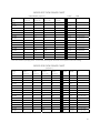
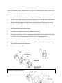
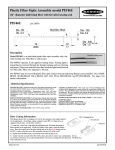
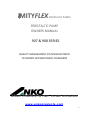
MITYFLEX PERISTALTIC PUMPS PERISTALTIC PUMP OWNERS MANUAL 907 & 908 SERIES QUALITY MANAGEMENT SYSTEM REGISTERED TO ISO9001 INTERNATIONAL STANDARDS ANKO PRODUCTS INC. PUMP DIVISION www.ankoproducts.com 1 Thank you for purchasing an Anko Mityflex® Peristaltic pump. We are sure you will be completely satisfied with its performance. Should you need assistance or have questions regarding the use or installation, please visit our website at www.ankoproducts.com. TABLE OF CONTENTS WARRANTY WARNING RETURN AND REPAIR PUMP FEATURES PUMP INSTALLATION FLOW CHARTS ROLLER SELECTION FUSE INSTALLATION/FAN ASSEMBLY TUBING INSTALLATION TUBING INSTALLATION PROCEDURE A TUBING INSTALLATION PROCEDURE B TUBING INSTALLATION PROCEDURE C ROLLER BRACKET ASSEMBLY ILLUSTRATION OF PUMP HEAD ASSEMBLY REPLACEMENT PARTS LIST 3 3 3 4 4 5 6 6 7 7 8 9 10 11 11 Every precaution for accuracy has been taken in the preparation of this manual, however, ANKO PRODUCTS, INC. neither assumes responsibility for any omissions or errors that may appear nor assumes liability for any damages that result from the use of the products in accordance with the information contained in this manual. 2 LIMITED WARRANTY ANKO PRODUCTS, INC., warrants equipment of its manufacture and bearing its identification to be free from defects in workmanship and material. ANKO PRODUCTS, INC.’s liability under this warranty extends for a period of one year from the date of delivery from our factory or authorized distributor. It is limited to repairing or replacing any device or part of any device which is returned, transportation prepaid, to the factory within one year of delivery to the original purchaser, and which is proven to be defective upon examination by us. ANKO PRODUCTS, INC. disclaims all liability for consequential damage of whatever nature, damage of equipment during transportation, damage, damage due to improper handling, installation or improper operation or for determining suitability for the particular use intended by a purchaser. Replaceable parts including tubes supplied with the product are not covered by any warranties either expressed or implied. ANKO PRODUCTS, INC., makes no warranties either express or implied, including implied warranty or merchantability, other than those stated above. No representative has authority to change or modify this warranty in any respect. Jurisdiction and venue for enforcement of this warranty may be brought only in the State of Florida. This warrant gives you specific legal rights, and you may also have other rights which vary from state to state. WARNING ANKO PRODUCTS, INC. assumes no responsibility or liability for chemical compatibility of our tubing in specific applications. ALWAYS pretest tubing in accordance with tubing manufacturer’s specifications. Tubing that shows signs of swelling, embrittlement, or other deterioration should not be used. RETURN AND REPAIR REQUESTS Please direct all warranty requests to the appropriate distributor the product was purchased from. 3 The MITYFLEX ® 907 and 908 models are fixed speed general purpose pumps for dispensing fluid based on products. The 907 is housed in a case and is controlled by a simple on/off switch that activates the pump. The 908 is manufactured with a zinc plated steel bracket and six inch lead wires for convenient assembly to your OEM application. FEATURES 1. 2. 3. 4. 5. 6. 7. 8. 9. ELECTRICAL: 115 VAC, 60HZ; OPTIONS: 24 to 240 VAC; 50Hz, 60Hz, or 50/60Hz; 12 & 24 VDC. The 907 also includes; On/Off switch; 6 foot power cord. PRIMING: Unit is self‐priming and will hold vacuum when off. OPERATION: Pump can run dry without damaging the motor or drive unit, however the tubing life will be reduced. CONSTRUCTION: Polypropylene housing and case using stainless steel fasteners. MAX. HEAD PRESSURE: Maximum working pressure 40 PSI. MAX. SUCTION LIFT: 29 feet (8.8m) with H₂O. RATING: AC Units‐ 100% of continuous operation at 25°C ambient; DC Units‐ 100% continuous operation at 40°C ambient. FLOW RATE: .4‐987 ml/min. Depending on the tubing used. (See page 5). FUSE: (907 only) Located on the exterior of the case. (See page 6 for replacement procedure and page 5 for fuse type). INSTALLATION INSTRUCTIONS 1. 2. 3. 4. POWER REQUIREMENTS: Voltage and frequency of power supply must be the same as shown on unit. WIRING CONNECTIONS: All wiring and electrical connections must comply with local and national electrical codes. MOUNTING: (907) Case enclosed model has rubber feet and mounting flanges. This enables it to be used on a flat surface or wall mounted. Be sure that one of the sets of vent holes has plenty of air for circulation. (908) Mounting brackets for OEM applications. Be sure there is plenty of space for air circulation. Do not allow tubing to be crimped. MOUNTING LOCATION: Pump should be placed in a dry location with adequate cooling provided. The ambient temperature should not exceed 25°C for AC units or 40°C for DC units.. WARNING This unit should not be used in outdoor or hazardous locations. 4 MODEL 907 FLOW RANGE CHART FLOW RATES (ml/min.) FUSE/ FAN Fuse Fan Tubing .062 In .125 In .187 In .250 In ID (1.6 m m) 93.2 m m) (4.7 m m) (6.3 m m) Unit # 907‐002 .4 1.7 4 7 .5 amp 907‐007 1.5 5.9 14 25 .5 amp None 907‐014 3 12 28 48 1 amp None 907‐023 5 19 46 81 1 amp 12‐1115‐18‐00 907‐028 6 24 56 98 2 amp 12‐1115‐18‐00 907‐036 8 30 72 126 1 amp 12‐1115‐20‐00 907‐049 10 41 98 172 5 amp 12‐1115‐25‐00 907‐058 12 49 116 208 2 amp 12‐1115‐18‐00 907‐075 16 63 150 263 3 amp 12‐1115‐18‐00 907‐108 23 91 216 378 3 amp 12‐1116‐18‐00 907‐129 27 108 258 452 3 amp 12‐1116‐18‐00 907‐172 36 144 344 602 3 amp 12‐1116‐18‐00 907‐203 43 170 406 711 3 amp 12‐1116‐18‐00 907‐282 60 237 564 987 5 amp 12‐1116‐18‐00 Flow rate based on pumping water ar 25°C and 0 PSI using 60 durometer thermoplastic elastomer tubing. MODEL 908 FLOW RANGE CHART (ml/min.) Tubing .062 In .125 In .187 In .250 In RPMS AMPS Fan ID (1.6 m m) 93.2 m m) (4.7 m m) (6.3 m m) Unit # 908‐002 .4 1.7 4 7 2 .37 908‐007 1.5 5.9 908‐014 3 12 14 25 7 .37 28 48 14 .37 908‐023 5 19 908‐028 6 24 46 81 23 .42 12‐1116‐18‐00 56 98 28 .75 12‐1116‐18‐00 908‐036 8 30 72 126 36 .90 12‐1116‐20‐00 908‐049 908‐058 10 41 98 172 49 1.0 12‐1116‐25‐00 12 49 116 208 58 1.2 12‐1116‐18‐00 908‐075 16 63 150 263 75 1.5 12‐1116‐18‐00 908‐108 23 91 216 378 108 1.9 12‐1115‐18‐00 908‐129 27 108 258 452 129 2.2 12‐1115‐18‐00 908‐172 36 144 344 602 172 2.2 12‐1115‐18‐00 908‐203 43 170 406 711 203 3.3/2.2 12‐1115‐18‐00 908‐282 60 237 564 987 282 3.3/2.2 12‐1115‐18‐00 Flow rate based on pumping water ar 25°C and 0 PSI using 60 durometer thermoplastic elastomer tubing. 5 ROLLER/TUBING SELECTION Use the following color coded rollers with the appropriate tubing I.D. Your unit is assembled with black rollers. Red rollers are included in your tubing kit. See separate instructions for roller replacement enclosed in your tube kit. Roller Tubing ID ML/Revolution Black 1/4” (.250) 3.5 Black 3/16” (.187) 2.1 Red 1/8” (.125) 0.8 Red 1/16”* 0.21 *The 1/16”ID tubing must be inserted into 3/16” (.187) ID X 3/8” (.375) OD tubing (sleeve) for operation in pump. FUSE INSTALLATION (907) (See page 4 for fuse type and page 10 for fuse ordering information) 1. Disconnect power to pump. 2. Remove four screws from case front. 3. Carefully remove case cover being sure not to pull wires apart. 4. Lay the unit on a flat surface. 5. Find fuse holder and pull apart. 6. Remove old fuse and replace with new fuse. 7. Replace case cover. FAN ASSEMBLY (See page 4 for replacement number) Disconnect the power from the pump. The fan is pressed on to the rotor shaft. On all 907 case units, the fan is pressed on with metal clip away from the motor. On all OEM 908 units, the fan is pressed on with the metal clip toward the door. 6 TUBING INSTALLATION Inspect all tubing regularly and replace if any sign of deterioration occurs. Always wear safety glasses and protective clothing when working with chemicals. See chart below for proper tubing installation procedure for your unit. *90_‐002 through 90_‐014 90_‐023 through 90_‐049 90_‐058 through 90_‐282 Procedure A (below) Procedure A or B (page 6 or 8) Procedure A or C (page 6 or 9) *WARNING: MODEL 907‐002, 907‐007, 907‐014, 908‐002, 908‐007 and 908‐014 GEARTRAINS CAN BE DAMAGED IF DRIVE SHAFT IS ROTATED BY HAND FOR TUBE INSERTION. PROCEDURE A (If unit is new start with step # 6.) 1. Disconnect power to the pump. 2. 3. 4. Disconnect the suction and discharge tubing from the pump tubing. Remove four screws and pump cover from pump head. Pull out old pump tubing and discard. 6. 7. 8. 9. 5. Clean roller race, removing and particles that could damage tubing. Connect power and run at slowest speed until roller bracket assembly is in position as shown in figure 1. Push new tubing into inlet port, anchoring tubing in grippers. If using a 9” piece of tube, 1 1/2” should be extended outside of inlet port. (figure 2) Continue to run at slowest speed carefully feeding tube into race as the rollers turn. (figure 3) (Keep fingers away from rollers). Insert tubing into outlet port (figure 4) and replace cover. 7 PROCEDURE B Follow steps 1‐5 in procedure A, then continue with the following. 6. Using extra bracket (figure 1), rotate roller bracket assembly until it is in position as in figure 2. (Be sure power is disconnected). 7. Push new tubing into inlet port, anchoring the tubing in grippers (see figure 3). If using 9” piece of tube, 1 1/2” should be extended outside of inlet port. 8. Continue to rotate the roller bracket assembly using the extra bracket, while pushing the tubing into the roller race. (figure 4) 9. Insert the tubing into the outer port (figure 5) and replace the cover and screws. 8 PROCEDURE C Without removing the pump cover, run the entire unit at high RPM. Pull the old tubing out from outlet port pump. Install new tube by inserting into inlet port; continue feeding tube 1/4” in at a time allowing the roller assembly to push tubing through. When tubing is half way around the race, put your finger over the inlet hole of the tube and continue to feed tubing 1/4” at a time, this should make installation easier. Continue until desired tubing extension is obtained. Run unit for about one minute. WARNING ANKO PRODUCTS, INC. assumes no responsibility or liability for chemical compatibility of our tubing in specific applications. ALWAYS pretest tubing in accordance with tubing manufacture’s specifications. Tubing that shows signs of swelling, embrittlement, or other deterioration should not be used. ROLLER BRACKET ASSEMBLY INSTRUCTIONS 9 For Roller Replacement (A plastic roller bracket assembly is supplied with units ranging from 2 to 108 RPM. No assembly is required for the plastic bracket. If new rollers are required a new assembly must be ordered). 1. To remove the roller bracket assembly from the pump, use a flat head screwdriver and pry open both sides of the springs to the edge of the bracket. 2. Pull the roller bracket assembly off the shaft holding on to the roller area of the bracket. 3. Holding the top and bottom of the bracket, slide the spring off to the side and lay the assembly on a flat surface. Try not to let it fall apart as you will need to put it together the same way it is now. 4. Remove the top bracket and the rollers. 5. If a roller pin comes out of its recess, replace it at this time. 6. Place the new rollers on the pins and replace the top bracket. Be sure that the flat in the inner hole of the top bracket lines up with the flat on the bottom bracket. 7. Slide the spring fastener back over the bracket. Do not snap the spring together. 8. Matching the roller bracket flat to the output shaft flat, slide the roller bracket assembly down until it stops without using force. 9. Snap the spring together. Illustration of the pump assembly. 10 1‐ Fan 2‐ Screw (1) 8‐32 x 7/8” 3‐ Gearmotor 4‐ Mounting Bracket (908 only) 5‐ Pump Housing 6‐ Tube 7‐ Screws (4) 10‐32 x 1 1/4” 8‐ *Nylon Washer 9‐ Roller Bracket Assembly 10‐ Pump Cover 11‐ Screws (4) 8‐32 x 5/8” The 908 mounting bracket is replaced with the 907 case cover on the case model. Replacement Parts List Contact your local distributor to order. Please remember to include the complete model number when you place your order for replacement parts. For fan orders use the chart on page 4 for the part number. Item Plastic Roller Bracket (Red)………………………………………… Plastic Roller Bracket (Black)……………………………………… Black Roller Bracket Assembly…………………………………… Red Roller Bracket Assembly…………………………………….. Pump Kit……………………………………………………………………. Unit Number RBA‐1718‐03‐25 RBA‐1718‐01‐25 RB‐1212‐01‐00 RB‐1212‐03‐00 907‐101‐0000‐10 Includes housing, cover, w/bearing, four screws, and washer. Tube Kit……………………………………………………………………… TU‐1124‐0000‐00 Includes 9” of each of the following: 1/16” ID (in a sleeve), 1//8” ID, 3/16” ID, and ¼” ID thermoplastic elastomer tubing. (See chart on page 5 for tubing and roller compatibility). Model 907 only: Fuses .5 amp (5/pack)……………………..FU‐1127‐00‐05 Fuses 1 amp (5/pack)……………………..FU‐1127‐01‐00 Fuses 2 amp (5/pack)……………………..FU‐1127‐02‐00 Fuses 3 amp (5/pack)……………………..FU‐1127‐03‐00 Fuses 5 amp (5/pack)……………………..FU‐1127‐05‐00 *No washer necessary for units using an all plastic roller bracket assembly. (2 to 36 RPM) (Copyright 12/97) 28‐4000‐00‐00 Revised 2/13/2002 11