1
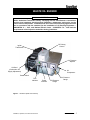
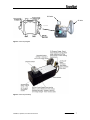
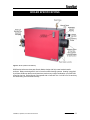
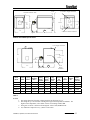
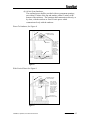
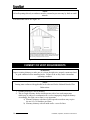
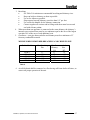
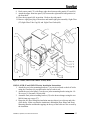
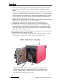
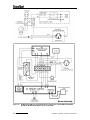
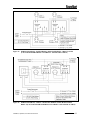
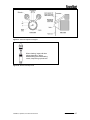
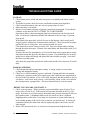
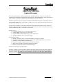
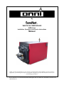
By
WASTE OIL FIRED BOILER
OWB Series
Installation, Operation, And Service Instructions
Manual
Thank you and congratulations on your purchase of an Omni Waste Oil Fired Boiler. You have selected a
high quality, precision-engineered piece of equipment, designed to give you many benefits as well as years
of outstanding performance.
Econo Heat♦5714 1st Avenue♦Spokane Washington 99212.♦(509)534-1022♦www.econoheat.com
100270 Rev A3
TABLE OF CONTENTS
WASTE OIL BURNER ........................................................................5
OIL BURNER TECHNOLOGY ..........................................................8
OIL BURNER/PUMP TECHNICAL DATA .......................................10
BOILER SPECIFICATIONS ...............................................................11
STANDARD EQUIPMENT.................................................................12
COMBUSTION AIR SUPPLY ............................................................14
CHIMNEY OR VENT REQUIREMENTS..........................................16
LOCATING THE BOILER ..................................................................18
INSTALLING THE BOILER...............................................................19
BREECHING INSTALLATION..........................................................19
INSTALLING BOILER CONTROLS AND ACCESSORIES ............20
WATER PIPING CONNECTIONS .....................................................22
SYSTEM PIPING.................................................................................24
BOILER ASSEMBLY AND WIRING ................................................33
BOILER STARTUP AND ADJUSTMENTS ......................................42
WASTE OIL BURNER STARTUP .....................................................43
WATER TREATMENT .......................................................................43
FREEZE PROTECTION ......................................................................43
MAINTENANCE .................................................................................44
TROUBLE SHOOTING GUIDE .........................................................46
WARRANTY .......................................................................................47
2
Installation, Operation, And Service Instructions
PRECAUTIONS
Waste oil may contain many foreign materials. Waste oil may also contain
gasoline. Therefore, specific precautions on the handling and storage of waste
oils are to be observed when using, cleaning and maintaining this heater. Use a
screen in a funnel when pouring oil into storage tank to catch foreign
material, i.e., gasket material and sealant fibers, etc. WARNING: This
appliance is not designated for use in hazardous atmospheres containing
flammable vapors or combustible dust, or atmospheres containing
chlorinated or halogenated hydrocarbons. Do not expose this unit to rain
or moisture. If installed in high moisture atmosphere, a special cover for
the integrated air compressor must be obtained from factory to avoid
rusting of internal raw metals. If this occurs, see trouble-shooting guide for
remedy. Uses only crank case oil, gear oil, hydraulic oils, auto trans. Fluid or #1
and #2 furnace oil. Do not use old, contaminated oils that have been stored in
underground tanks or outside barrels for long periods. Excessive water and
sludge may be present, causing quick filter plugging.
NOTES: The instructions contained in this manual apply to the installation,
operation, and service of Omni Waste oil fired boiler. The following instructions
should be carefully followed for obtaining the best possible installation, operation
and service conditions. Specifications are subject to change without notice. This
product was designed to provide an economical disposal of waste oil. Proper
operation depends on the consistency of the oil. Any water or foreign material in
the oil may cause the unit to shut down.
This appliance is designed for commercial or industrial use only.
UNCRATING: Immediately upon uncrating units, check rating plate for certainty
of electrical and mechanical characteristics. Also check the unit for any damage
that may have been incurred in shipment, if any damage is found, file a claim
with the transporting agency. The unit has been tested and inspected at the
factory prior to crating and was in perfect condition at that time. If anything is
missing check packing slip for indications of possible backorder of those parts or
components. Otherwise a claim must be for those missing parts.
Installation, Operation, And Service Instructions
3
IMPORTANT
NOTICE TO OWNER
AND INSTALLER
To enjoy the long term benefits of burning your used oil in an Omni Waste Oil Boiler, it is
necessary to become familiar with the correct installation operation and maintenance of your new
boiler. Before installing or operating this appliance, make sure you read and understand this
manual.
IMPROPER INSTALLATION OR LACK OF
MAINTENANCE
WILL VOID THE WARRANTY
------------WARNING-----------Improper Installation, adjustment, alteration service or
maintenance can cause property damage, injury, or loss
of life. For assistance or additional information consult
a qualified installer or service agency. Read these
instructions carefully before installing
Identical to any oil burning appliance, without adequate draft over the fire, the combustion
gases cannot escape the appliance. The flame will lengthen resulting in an overheated
combustion chamber. Even if the heater is installed correctly and adequate draft achieved, a
flue passage blockage will affect the draft. Burning used oil is similar to burning wood. A fine gray
ash accumulates in the chamber and flue passage. This accumulation of ash will eventually affect
the draft. It is important to remove this ash before the draft is affected.
Note:
All illustrations and specifications contained herein are based on
the latest information available at time of publication approval.
Econo Heat reserves the right to make changes at any time
without notice, in material and specifications.
4
Installation, Operation, And Service Instructions
WASTE OIL BURNER
WARNING
ONLY Authorized Technicians strictly complying with the manufacturer’s instructions
and the local standards should perform installation, maintenance and service on the
unit’s internal components. Installation and use of this used oil burning appliance shall
be in accordance with the standard for the Installation of Oil Burning Equipment –
ANSI/NFPA 31 – 1987, and National Electric Code – ANSI/NFPA 70 – 1990 and the
requirements of the inspection authorities having jurisdiction.
Oil Primary
Control
Igniter
Transformer
Air Pressure
Adjuster
Air Band
(Combustion Air
Supply Adjustment)
Air
Compressor
Power Switch
Run
Indicator
Power
Indicator
Oil Pressure
Gauge
Air Pressure
Gauge
Figure 1 – Oil Burner (Back View Closed)
Installation, Operation, And Service Instructions
5
Pre-Heater Control
Circuit Board
Oil Pre-Heater
Block
Air
Muffler/Filter
Photo Eye
Flame Sensor
Electrical
Terminal
Block
Transformer
Igniter Springs
Heater
Electrical
Schematic
Figure 2 – Oil Burner (Back View Opened)
Electrodes
Oil Valve
Nozzle
Burner
Motor
Flame Cone
Figure 3 – Oil Burner (Front View)
6
Installation, Operation, And Service Instructions
Oil Outlet
Oil Inlet
Figure 4 –Oil Pump Diagram
Figure 5 –Oil Pump Assembly
Installation, Operation, And Service Instructions
7
OIL BURNER TECHNOLOGY
Omni’s patented burner technology improves the efficiency of the oil burn process by continuous
stabilization of the oil viscosity. Optimum atomization (spray) is accomplished by precisely preheating the oil and air prior to introduction to the combustion chamber. The waste oil enters into
the Oil Pre-Heater Block (figure2) and is pre-heated to operating thermo setpoint, then
compressed air from the air compressor (figure1) is mixed with the oil prior to spraying out the
nozzle similar to fuel injection, by breaking up the oil droplets into a finer mist or spray
(atomization). Electrodes mounted just above the nozzle (figure3) provides continuous electrical
arc across electrode to electrode igniting the fine oil mist as it sprays out of the nozzle. Once
ignited the flame is forced into a swirl caused by the burners blower and specially designed flame
cone (figure3) providing a very efficient and thorough burn of the waste oil.
Burner Components
8
•
Igniter Transformer: (figure1) Supplies high voltage to the electrodes generating
electrical arc igniting the oil.
•
Oil Valve: (figure3) energizes when burner is running and de-energizes when burner is
not running eliminating bleed back of oil out of the Pre-heater block.
•
Air Band: (figure1) Adjusts amount of air introduced into the combustion chamber.
•
Oil Primary Control: (figure1) Controls the oil burner ignition. Checks for flame in the
combustion chamber, if no flame is detected within 45 seconds, the oil primary will
shutdown the oil burner. To restart the unit, reset the red button on the oil primary.
•
Oil Pre-Heater Block: (figure2) Pre-heats the oil and air before entering combustion
chamber.
•
Photo Eye: (figure2) Senses flame in combustion chamber and signals oil primary when
no flame is present.
•
Igniter Springs: (figure2) Transfers the high voltage from the igniter transformer to the
electrodes (when door is closed)
•
Air Pressure Gauge: (figure1) Displays air pressure supplied by onboard air
compressor.
•
Air Compressor: (figure1) Supplies air used within pre-heater block to aid in atomization
of the oil.
•
Air Muffler/Filter: (figure2) Filters air and muffles the sound generated by the
compressor.
•
Pre-Heater Control Circuit Board: (figure2) Precisely controls temperature of the Oil
Pre-Heater Block and controls safety feature of not allowing burner to energize until oil
has established operating thermo setpoint or shutdown burner if Pre-Heater Block
temperature falls below shutdown thermo setpoint.
•
Electrodes: (figure3) Provides continuous high voltage electrical arc from electrode to
electrode igniting the waste oil as it is being sprayed out of the nozzle.
•
Nozzle: (figure3) Low pressure nozzle for oil spray pattern.
•
Flame Cone: (figure3) Specially engineered flame cone forces the flame into a swirl
pattern improving the burn thoroughness.
•
Burner Motor: (figure3) Multitask motor turns the burner blower and integrated air
compressor.
Installation, Operation, And Service Instructions
•
Air Pressure Adjuster: (figure1) Adjusts the air pressure going to the pre-heater block.
Should be adjusted between 12 PSI and 13PSI as indicated on the Air Pressure Gauge
on the burner for thorough burn of the waste oil.
Note: In order to insure proper air adjustment, air gauge must read 0 when burner
is cycled off or powered down.
•
Oil Pressure Gauge: (figure1) Displays oil pressure at the burner. Adjustment at the Oil
Pump must be made to achieve oil pressure readings at the burner as indicated below.
Boiler Model
Oil Pressure Reading At
Burner
OWB-9
1 PSI
OWB-15
2 PSI
OWB-25
4 PSI
OWB-35
6 PSI
OWB-50
11 PSI
•
Power Indicator: (figure1) Indicates when power is present at the burner.
•
Run Indicator: (figure1) Indicates that the burner is ready for operation after the initial
pre-heat time of approx. 5 minutes from initial power up.
•
Power Switch: (figure1) Switches power off and on to the burner.
Installation, Operation, And Service Instructions
9
OIL BURNER/PUMP TECHNICAL DATA
BURNER ASSEMBLY
Performance Ratings
Voltage
Cycles
Total Operating Amperage (Burner Only)
Total Operating Amperage (Burner and Oil Pump)
Electrical Operating Consumption (Burner Only)
Electrical Operating Consumption (Burner and Oil Pump)
Weight
Oil Primary
Oil Valve
Pre-Heater Block
Pre-Heater Controller Board
Igniter Transformer
Burner Motor
Amp
Amp
Watts
Watts
Lbs
Amp
Amp
Amp
Amp
Amp
Amp
115 VAC
60Hz
8.4
10.5
970
1,212
36.5
0.2
0.075
4.2
0.011
0.3
3.6
Amps
Watts
Lbs
Amps
Amps
115Vac
60Hz
2.1
241.5
16
0.075
2.0
PUMP ASSEMBLY
Performance Ratings
Voltage
Cycles
Total Operating Amperage (Pump Assy Only)
Electrical Operating Consumption (Pump Assy Only)
Weight
Oil Valve
Pump Motor
10
Installation, Operation, And Service Instructions
BOILER SPECIFICATIONS
Figure 6 –Boiler (OWB-35 & OWB-50)
OWB series boilers are three pass Scotch Marine design with fully water backed transfer
surfaces. Boilers are designed for use in forced hot water heating systems. Heating is supplied
by a Waste Oil Burner that burns all petroleum products any weight combination up to SAE 90W
as well as fuel oils. Boiler–Burner units operate with no less than 0 to –0.01WC over fire and may
be vented using a conventional chimney.
Installation, Operation, And Service Instructions
11
CODE REQUIREMENTS
Installations must comply with all state, local, and utility codes, laws, regulations, and
ordinances, and CSA standard B139. Where required by the authority having
jurisdiction, the installation must conform to American society of Mechanical Engineers
Safety Code for Controls and Safety Devices for Automatically Fired Boilers, No. CSD1.
All electrical wiring must be done in accordance with the National Electrical codes latest
edition and all state and local codes.
STANDARD EQUIPMENT
* Factory Assembled Cast Iron Sections
* Flow Control Oil Supply Pump
* Insulated Jacket
* Theraltimeter Gauge
* Boiler Drain
* Circulator – Except Models 35 and 50
* Relay – Models 35 and 50 Only
* Pre-built Control Manifold
Models 35 and 50 Only
12
* Refractory Insulated Hinged front
Door With Sight Glass
* ASME Relief Valve 30 PSI
* Draft Inducer (optional)
* High Limit Aquastat Relay Combination
(L-8148°) Except Models 35 and 50
* Serviceable Oil Filter
* Low Water Cut-off Control
* Manual Reset High Limit Aquastat Control
Installation, Operation, And Service Instructions
9-3/8”
Centerline Of Burner Plate
2-1/2 M.P.T. Supply Connection
36”
29-1/2”
20”
17”
3/4”
L
33”
4”
8”
2-1/2 F.P.T. Return Connection
Approx. 14”
OWB-35 and OWB-50 Specifications
1-1/2” Supply Connection
26”
Circulator
21-1/2”
15-1/2”
12-1/4”
1-1/2”
Return
Connection
L
25”
Approx. 14”
OWB-9, OWB-15, and OWB-25 Specifications
Boiler
Model
Burner
GPH
Input
BTU’s
Output
Capacity
BTU’s
NET
Rating
Water
BTU/HR.
NET
Rating
Water
SQ.FT.
Approx.
Dry
Weight
Lbs.
Vent
Connect
Dia.
Inches
Dim
“L”
Inches
Water
Content
Gal.
Max.
Water
Working
Pressure
OWB-9
.60
90,000
76,500
66,500
522
527
7
24-1/4
5.5
60PSI
OWB-15
1.0
150,000
127,500
110,800
875
716
7
34-1/4
8.2
60PSI
OWB-25
1.7
250,000
212,500
184,700
1,450
902
7
44-1/4
10.8
60PSI
OWB-35
2.4
350,000
297,500
258,600
2,030
1654
10
52
28.5
75PSI
OWB-50
3.3
500,000
425,000
369,500
2,900
1831
10
57
31.7
75PSI
Table 1.
NOTES:
1.
2.
3.
4.
Net ratings shown are based on a piping and pick-up allowance of 1.15.
Net ratings in sq. ft. are based on 170 deg F average water temperature in radiators. For
higher water temperatures, select boiler on basis of net ratings in BTU/HR.
Firing rate in G.P.H. is based on oil having heat value of 150,000 BTU/GAL.
4% reduction of output for every 1,000 ft. of elevation.
Installation, Operation, And Service Instructions
13
COMBUSTION AIR SUPPLY
WARNING
Failure to provide an adequate supply of fresh air for combustion will result in hazardous
operating conditions.
Note
If you use a fireplace or a kitchen or bathroom exhaust fan, you should install an outside
air intake. These devices will rob the boiler and water heater of combustion air.
1. In unconfined spaces in buildings infiltration may be adequate to provide air for
combustion and ventilation. However, in buildings of unusually tight
construction, additional air must be provided as described in Item2. (b) below.
2. Boiler located in confined space:
[Note: Confined space may be defined as a space whose volume is less than 50
cubic feet per 1000 Btuh of total input of all appliances installed in that space.]
(a) All air from inside of building:
Providing infiltration in the rest of the building is adequate, the
confined space may be provided with two permanent openings
communicating directly with another room or rooms of sufficient
volume that the total volume of all spaces meets the criteria for
unconfined space. One opening must be within 12 inches of the
bottom of the enclosure. See Figure 7.
Chimney
Opening
Note: Each opening
shall have a free
area of not less than
one square inch per
1,000 Btu per hour of
the total input rating
of all equipment in
the enclosure, but
not less than 100
square inches.
Opening
Figure 7.
14
Installation, Operation, And Service Instructions
(b) All Air From Outdoors:
The confined space shall be provided with two permanent openings,
one within 12 inches of the top and another within 12 inches of the
bottom of the enclosure. The openings shall communicate directly, or
by ducts, with the outdoors or crawl or attic spaces which
communicate freely with the outdoors.
Direct To Outdoors, See Figure 8.
Chimney
Ventallation Louvers
(each end of attic)
Outlet Air
Alternative
Air Inlet
Inlet Air
Note: The inlet
and outlet air
openings shall
each have a
free area of
not less than
one square
inch per 4,000
Btu per hour of
total input
rating of all
equipment in
the enclosure.
Ventallation Louvers for Unheated Crawl Space
Figure 8.
With Vertical Ducts See Figure 9.
Chimney
Ventallation Louvers
(each end of attic)
Outlet Air
Note: The inlet
and outlet shall
each have a free
area of not less
than one square
inch per 4,000
Btu per hour of
the total input
rating of all
equipment in the
enclosure.
Inlet Air Duct
(ends 1 ft. above floor)
Figure 9.
Installation, Operation, And Service Instructions
15
NOTE
All wall openings directly to outdoors must be screened to prevent entry by birds or small
animals.
With Horizontal Ducts See Figure 10.
Chimney
Note: Each air duct opening
shall have a free area of not
less than one square inch
per 2,000 Btu per hour of the
total input rating of all
equipment in the enclosure.*
Outlet Air Duct
Inlet Air Duct
*If the equipment room is located against an outside wall and the air
openings communicate directly with the outdoors, each opening shall have
a free area of not less than one square inch per 4,000 Btu per hour of the
total input rating of all equipment in the enclosure.
Figure 10.
CHIMNEY OR VENT REQUIREMENTS
WARNING
Inspect existing chimney to make sure it is clean, the right size, properly constructed and
in good condition before installing boiler. Failure to do so may cause a hazardous
operating condition.
NOTE
Venting must conform with applicable local codes and for the National Board of Fire
Underwriters.
1. Chimney must be a Class A chimney.
2. This is a high efficiency boiler which operates with a low stack temperature
which may be subject to condensation in a cool or improperly designed chimney.
Accordingly, the right vent or liner is very important.
a) Masonry chimney with three walls exposed to outdoors may require
the use of a 316 stainless steel liner.
b) Masonry chimney with all inside walls—use a tile liner.
16
Installation, Operation, And Service Instructions
3. Breeching
•
See Table 2 for minimum recommended breeching and chimney sizes.
•
Keep run boiler to chimney as short as possible.
•
Use as few elbows as possible.
•
Slope upward towards chimney at not less than 1/4” per foot.
•
Use a sealed-in thimble for the chimney connection.
•
Connect together all sections and/or fittings with sheet metal screws and
seal with silicone sealant.
4. When more than one appliance is connected to the same chimney, the chimney’s
internal cross-sectional area must be at a minimum equal to the area of the largest
vent plus 50% of the area of each additional vent.
5. Clearances—vent pipe between boiler and chimney must be a minimum of 6”
from any combustible material.
MINIMUM RECOMMENDED BREACHING AND CHIMNEY SIZE.
Boiler Model
Min. Breeching
Dia.
OWB-9
OWB-15
OWB-25
OWB-35
OWB-50
6”
7”
7”
10”
10”
Min. Recommended
Chimney
Size
I.D.
HT.
6”
15’
7”
15’
8”
20’
10”
15’
10”
15’
Table 2.
6. An oil-fired unit shall be connected to a flue having sufficient draft at all times, to
assure safe proper operation of the unit.
Installation, Operation, And Service Instructions
17
SIDE-WALL VENTING---IMPORTANT NOTE
Two problems arise when side wall venting any oil appliance;
1. There is sometimes an accelerated rate at which soot builds up on the cad-cell,
spinner, etc.
2. There is the potential for severe soot damage to the side of the structure in the
event that the boiler operates at a high smoke level. This can happen for many
reasons, some of which are out of the control of both the installer and
appliance manufacturer.
Econo Heat recommends the use of a chimney to vent our residential oil boilers. If a
power venter must be used, it is the responsibility of the installer and power vent
manufacturer to “engineer” the power vent system.
ECONO HEAT WILL ASSUME NO REPONSIBILITY FOR SOOT DAMAGE
TO SIDING, ETC. FROM A POWER VENTED OIL BOILER. THIS
APPLIES REGARDLESS OF THE CAUSE OF THE SOOTING.
LOCATING THE BOILER
WARNING
Boiler must not be installed in an area where gasoline, paint or other combustible
materials or flammable vapors or liquids are present.
1. Consider all piping and venting connections before selecting a location. Locate as
close to the chimney as possible, observing the following clearances requirements
from combustible surfaces:
Front ......................24”
Top ......................... 6” above controls
Left Side ................. 6”
Right Side ............... 6”
Back ........................18”
2. Boiler is not intended for installation on combustible floor. Further, to facilitate
servicing it is desirable to raise the boiler at least 8” off the floor. It is
recommended that concrete blocks be employed to build up a foundation. Ensure
that top surface of foundation is level.
18
Installation, Operation, And Service Instructions
INSTALLING THE BOILER
Placing The Boiler (OWB-9 – OWB-25)
1. Move the boiler as close as possible to its final location in the crate.
2. Remove the two lag screws holding the rear feet to the skid.
3. Remove the front jacket panel. Cut the band holding the front of the boiler to the
skid.
4. Move the boiler into the final position.
5. Waste Oil Piping: USE ONLY 3/8” nominal ID copper tubing with flare fittings only on the
oil suction from the tank to the oil pump and oil pump to burner. DO NOT use ferrule
fittings or teflon tape on any pipe fittings. Keep suction line approximately 6” from
bottom of oil tank to prevent suction of sludge (Figure 11). Use only an inside oil storage
tank. Do Not draw from an outside tank, especially not an underground tank directly to
burner. A separate transfer pump from an outside tank with proper filtration to the inside
supply tank is acceptable.
6. The fuel pump included with burner is to be mounted at tank level or below. PUMP MUST
BE MOUNTED HORIZONTAL AND LOCATED NEXT TO WASTE OIL SUPPLY TANK.
1, Oil Feed Line, 3/8” to connector on burner gun assembly
2,O Suction Line, 3/8” copper tubing
3, Suction Line 6” min from bottom of tank to prevent sludge from being introduced into
the supply line
1
2
3
Waste Oil Supply Tank
Waste Oil Pump
Boiler
Figure 11.
BREECHING INSTALLATION
The breeching connection on OWB-9, OWB-15 and OWB-25 is 7 inches regardless of
input. Refer to Table 1 for minimum breeching sizes. Breeching run should be as short
as possible with as few elbows a practical. Unless marginal draft conditions exist, a
brametric draft control must be installed in the breeching and should be approximately 18
inches from the boiler breeching connection. Breeching should not project into the
chimney beyond the inside wall of the chimney. Connect the breeching to the chimney
with a thimble or slip joint to facilitate cleaning. See Figure 12.
Installation, Operation, And Service Instructions
19
Pitch Up 1/4” per foot
Barometric Draft Control
18”
Straight Run Preferred
Figure 12.
INSTALLING THE BOILER CONTROLS AND
ACCESSORIES
1. Accessories for Boilers OWB-9, OWB-15, and OWB-25:
a) Take the L8148A Aquastat relay, the well, the pressure relief valve with pipe
nipple and the temperature/pressure gauge from the large carton which was
packed in the wirebound crate. Install in tappings provided at the top rear of the
boiler as shown in Figure 13.
Figure 13.
b)
c)
20
Take the boiler drain from the same carton and connect it to the 3/4 inch opening
of the 1 1/4 x 3/4 x 1 1/4 inch tee in the boiler return manifold at the bottom rear
of boiler.
Install 1 1/4 x 3” Nipple and Circulator Flange.
Installation, Operation, And Service Instructions
d)
Remove the circulating pump from its carton in the crate and mount it to the
pump flange on the end of the return manifold.
2. Bare Boiler:
a)
b)
1.
The pressure relief valve and temperature/pressure gauge are supplied with the
boiler and should be mounted as shown in Figure 13.
The bare boiler does not include the return manifold. The installer must make up
his own manifold to connect to the 2 x 1 1/4 inch bushing which is supplied in the
boiler supply and return ports, and must provide his own boiler drain and
circulating pump.
Accessories for Boilers OWB-35 and OWB-50:
Figure 14. Supply Manifold Assembly
Figure 15. Return Diffuser Installation
a) Attach supply manifold as shown in Figure 14.
b) Install return port diffuser and attach return flange as shown in Figure 15. Make
sure diffuser SLOTS face upward.
c) Screw threading used on these parts are metric. There is no english thread
equivalent to the nuts or studs supplied. Attempts to use any english threaded
stud in place of those supplied will damage the boiler block.
Installation, Operation, And Service Instructions
21
WATER PIPING CONNECTIONS
1. OWB-9, OWB-15, and OWB-25 boilers are shipped complete with circulating pump.
To make the piping connections to the boiler ready to connect to the system piping,
the following will also be required at a minimum:
1 – Air Purger (same size as supply pipe)
1 – Pressure reducing Fill Valve
1 – Expansion Tank (sized to system design requirements)
1 – Automatic Air Vent
2. The following accessories may also be required, depending upon overall system
design and code requirements:
1 – Low Water Cutoff may be required if boiler is located above radiation level.
Check requirements of state or local code bodies and insurance companies. If
required use a probe-type designed for water system use and install in tee in
supply piping above the boiler.
1 – Manual Reset High Limit----Required by some state or local codes. Also
required if system is to comply with ASME code.
1 – Backflow Preventer----- Required by many State and local codes.
3. Additional circulating pumps or zone valves may also be required if the system is to
be multi-zone or if it is to include a domestic hot water storage tank with coil.
WARNING
The expansion tank must be properly sized to system requirements. An under-sized
expansion tank will cause system water to be lost through the relief valve and make-up
water to be introduced through the fill valve. Continual introduction of fresh water into
the system will cause mineral build-up in the boiler sections and eventual section failure.
4. There are two types of expansion tanks used, the closed type and the pre-pressurized
diaphragm tank Most new installations use the diaphragm type tank, however some
installations still employ the closed type tank.
(a) Piping Connections with closed type expansion tank----See Figure 16. Piping
from tee in supply to tank should be 3/4 inch. If horizontal piping is
employed, pipe must be pitched up toward tank 1/4 inch per foot.
22
Installation, Operation, And Service Instructions
Closed Type Expansion Tank
Pressure Relief Valve
3/4 in.
Supply
to
System
Shutoff Valve
S
Cold Water Feed
Fill Valve
R
Return From System
Drain Cock
Circulation Pump
Figure 16.
(b) Piping connections with diaphragm expansion tank--- See Figure 17.
The cold water feed to the pressure reducing fill valve may be piped with 1/2
inch pipe.
Shutoff Valve
Purger
Auto Air Vent
S
Cold Water Feed
Diaphragm Type
Expansion Tank
R
Drain Cock
Circulator Pump
Figure 17.
Installation, Operation, And Service Instructions
23
SYSTEM PIPING
Supply and return and system piping should be sized by determining the pressure drop,
required flow rate and pump capacity.
WARNING
Discharge piping from relief valve must be piped to a drain or must terminate 6” above
floor to eliminate damage to the structure or personal injury. It must not be piped to a
point where freezing might occur.
1. MULTIPLE ZOINING WITH ZONE VALVES -----
See Figure 18. Install a balancing valve in each zone and adjust so that flow is about
the same in each zone.
Isolation Valves
Shutoff Valves
S
Cold Water Feed
R
Zone Valves
Drain Cock
Circulation Pump
Figure 18.
24
Installation, Operation, And Service Instructions
Isolation Valves
Flow Control Valves
Shutoff Valve
S
Cold Water Feed
R
Drain Cock
Isolation Valves
Circulating Pumps
Figure 19.
2. MULTIPLE ZONING WITH CIRCULATORS -----
Each pump will require a separate relay (Honeywell R845A or White Rodgers 829A845, or equivalent). Install a flow control valve in each zone including the indirect
water heater to prevent gravity circulation. Install a balancing valve in each zone and
adjust so that flow in each zone is about the same. See Figure 19.
3. RADIANT PANEL OR OTHER LOW TEMPERATURE SYSTEM----
The temperature of the system water coming back to the return port of the boiler must
not be permitted to drop below about 135 Degree F for an extended period of time.
Return water temperatures of 130 Degree F or lower will cause condensation on the
exterior surface of the heat exchanger and corrosion and eventual heat exchanger
failure will result. Radiant floor and ceiling panel heating systems typically operate
with maximum supply water temperatures of 140 Degree F or less. A standard piping
arrangement would, under these circumstances, permit return water temperatures of
120 Degree F and lower. Accordingly, such systems must be piped such that the
return water temperature will be high enough at all times to prevent condensation.
See Figure 20.
Installation, Operation, And Service Instructions
25
Return from System
Supply to System
Stem Thermometer
Shutoff Valve
Circulating Pumps
S
Bypass A
Cold Water Feed
R
Drain Cock
Circulating Pumps
Adjust the two manual valves to maintain 160 degree F or more in the boiler while holding the supply water
temperature at the stem thermometer at 140 degree F or whatever minimum temperature system requires.
Figure 20.
NOTE
Bypass A shown in figure 20. above should not exceed 12 inches in length. If it
is not practical to maintain a 12 inch length or less then increase the pipe size of
the bypass by one size.
4. LARGE WATER CONTENT SYSTEMS------
Such systems as converted gravity systems, old systems with cast iron radiators, and
also newer systems that employ outdoor reset control present a potential problem with
low return water temperatures and condensation. The boiler must be protected from
condensation in such cases by using a by-pass as shown in Figure 21.
26
Installation, Operation, And Service Instructions
Supply to System
Shutoff Valve
S
Cold Water Feed
R
Return from System
Circulating Pumps
Drain Cock
Adjust the two manual valves to maintain 135 degree F or more in the
boiler with return water at the lowest temperature to be expected.
Figure 21.
5. INTEGRATED SYSTEM (HEAT AND DOMESTIC HOT WATER) -----
With a single heating zone priority for domestic hot water may be provided through
the use of a 3-port zone valve. This system assures that full boiler output is available
to recover the storage tank quickly and should be used where supply of domestic hot
water on demand is critical.
For this application use a full throated valve with a minimum pressure drop. See
Figure 22.
Installation, Operation, And Service Instructions
27
Indirect Water Heater
(Storage Tank With Coil)
Supply to System
Shutoff Valve
S
3 Port Zone Valve
Cold Water Feed
R
Return from System
Drain Cock
Circulating Pumps
Figure 22.
6. INTEGRATED SYSTEM WITH MULTIPLE HEATING ZONES AND NO
PRIORITY FOR DOMESTIC HOT WATER, USING ZONE VALVES----Where the boiler output is large relative to the heating capacity of the coil in the
indirect water heater priority for domestic hot water is not necessary. Further, with
multiple heating zones there is less likelihood that all zones will call for heat at once
and require full boiler output for heating. Because the tank is usually close to the
boiler, the pressure drop through the coil circuit will generally be less than through a
heating zone circuit, which will provide some measure of priority for domestic hot
water. This can be enhanced by increasing the pipe size to the coil e.g. if 3/4 inch
pipe is used on the heating zones run 1 inch pipe to the coil. (See Figure 23.) Should
priority for domestic hot water be mandatory, it can be provided as shown in Wiring
Section, Figure 24.
28
Installation, Operation, And Service Instructions
Indirect Water Heater
Supply to System
Shutoff Valve
S
Zone Valves
R
Cold Water Feed
Return from System
Drain Cock
Circulating Pumps
Figure 23.
7. INTEGRATED SYSTEM, SINGLE OR MULTIPLE HEATING ZONES,
USING CIRCULATING PUMPS RATHER THAN ZONE VALVES---Each pump will require a separate relay (Honeywell R845A or White Rodgers 828A845, or equivalent). Install a flow control valve in each zone including the indirect
water heater to prevent gravity circulation. Install a balancing valve in each zone and
adjust so that flow in each zone is about the same. (see Figure 24.) While this basic
system does not provide priority for domestic hot water, priority can be provided as
shown in Wiring Section, Figure 27.
Indirect Water Heater
Supply to System
Shutoff Valve
S
Flow Control Valves
Cold Water Feed
Return from System
R
Circulating Pumps
Drain Cock
Figure 24.
Installation, Operation, And Service Instructions
29
8. COMBINATION HEATING/COOLING SYSTEM WITH CHILLED WATER
The chiller must be piped in parallel with the boiler and isolation valves installed to
prevent the chilled water from circulating through the boiler and heated water from
circulating through the chiller. See Figure 25.
Chiller
Insulation Valve # 4
Supply to System
Insulation
Valve # 4
S
Circulating Pumps
Insulation Valve # 3
Return from System
Cold Water Feed
R
Flow Check
Drain Cock
Note:
1.
When in cooling mode isolation valves 1 and 2 must be closed and valves 3 and 4 open.
2.
When in heating mode isolation valves 1 and 2 must be open and valves 3 and 4 closed.
Figure 25.
9.
SINGLE BOILER PIPING WITH BLEND PUMP
When burner is operating the water flow throughout the boiler shall be not less than
1.8 GPM for each 100,000 BTU/HR of gross boiler output. Size blend pump
accordingly. See Table 3
Blend Pump
Boiler Model
GPM
Primary/Secondary
Pump
GPM
OWB-9
OWB-15
OWB-25
OWB-35
16.3
78.9
OWB-50
19.6
94.9
Maximum water flow resistance for boilers is 14” w.c
Table 3.
30
Installation, Operation, And Service Instructions
Amtrol #720 Air
Eliminator or Equal
System
Supply
Air
Separator
S
System
Circulator
R
Pressure
Reduction
Valve
Blend Pump
To Size Blend
Pump See Table 3
Backflow
Preventer
System
Return
Check Valve
From City
Water Supply
Expansion Tank
Figure 26.
10. SINGLE OR MULTIPLE BOILER PIPING FOR PRIMARY/SECONDARY
PUMPING
Size Secondary Pump GPM at Gross Boiler Output for 20” Drop. When Calulating
Pump Head, the Maximum Boiler Resistance for any Boiler will not Exceed 14 in.
W.C. Head.
Amtrol #720 Air
Eliminator or Equal
Secondary
Pump
System
Supply
S
Check Valve
S
R
Secondary
Pump
R
Air Separator
Pressure
Reduction
Valve
Check Valve
12” MAX
System
Return
System
Circulator
12” MAX
Expansion Tank
Backflow
Preventer
From
City
Water
Supply
Figure 27.
Installation, Operation, And Service Instructions
31
11. MULTIPLE BOILER PIPING- REVERSE RETURN FLOW WITH BLEND
PUMP
Amtrol #720 Air
Eliminator or Equal
S
S
R
Check Valve
Air Separator
System
Supply
System
Circulator
R
Pressure
Reduction
Valve
*Blend Pump
Backflow
Preventer
*Blend Pump
Check Valve
System
Return
Expansion Tank
From
City
Water
Supply
Figure 28.
32
Installation, Operation, And Service Instructions
BOILER ASSEMBLY & WIRING
Burner Mounting
NOTE:
When the burner is field installed the installer must fill in the space between the burner
blast tube and the insulation block on the inside of the burner door with refractory mix
provided.
Figure 29. OWB-35 and OWB-50 Burner Mounting & Boiler Door Detail
Figure 30. OWB-9, OWB-15 and OWB-25 Burner Mounting & Boiler Door Detail
Installation, Operation, And Service Instructions
33
Boiler Jacket Assembly
26
25
26A
Sight
Class
Assy
33
86
60
38
48
94
36
43
18
41
93
18
40
Figure 31. OWB-35 and OWB-50 Assembly Detail
OWB-35 and OWB-50 Jacket Installation Instructions
1. Screw the four extension setscrews (43) into the four outer holes in the corners of
the rear sections. Securely tighten the setscrews and other fastening bolts of the
flue outlet cover (22)
2. Place the large wraparound insulation mat (40) over boiler block (aluminum foil
side facing out).
3. Place smaller piece of insulation on top of wraparound insulation. This will
provide double thick insulation on top of the boiler block.
4. Remove flue collector clean-out covers (62)
5. Push the two smaller pieces of insulation (60) onto the flue collector (22) so that
the four extension setscrews (43) protrude through the insulation.
6. Attach rear jacket panels (36) and (38) to the two extension screws(43) using the
M6x10 pan head screws. Screw the rear panels together in the center using sheet
metal screws provided. Reattach the clean-out covers.
7. Place right and left side panels (93) (94) into the factory mounted hinge bracket
(18) and hook into the rear panels (36) (38).
34
Installation, Operation, And Service Instructions
8. Hook center panel (33) with flange edge down between side panels (93) and (94).
9. Attach the upper front trim panel (41) between the right and left side panels over
the front door.
10. Place the top panel (86) in position. Hook to the side panels.
11. Remove sight glass plug in front door and install sight glass assembly. Sight Glass
(25) Sight Glass Tube Cap(26) and Sight Class Gasket(48).
Figure 32. OWB-9, OWB-15 and OWB-25 Assembly Detail
OWB-9, OWB-15 and OWB-25 Jacket Installation Instructions
1. Attach the rear jacket mounting brackets (7) to rear tie rod ends on back of boiler
using the 12mm nut (9) provided on the end of each tie rod.
2. Attach the rear jacket panel (3) to the rear jacket mounting bracket using the 1/420 screws (11) ans nuts (10) provided.
3. Assemble front jacket mounting bracket (23) to the heat exchanger using the two
M10x16mm cap screws (27).
4. Drape the foil faced fiberglass insulation mat (not shown) over the top and sides
of the boiler. Make sure that the insulation is behind the Door Hinge and Front
Mounting Bracket and that the tappings in the top of the boiler are not covered by
the insulation.
Installation, Operation, And Service Instructions
35
5. Attach one door bracket (18) to the bottom of both the left and right side jacket
panels. Use two 8-32x1/2” screws (19) and nuts (20) to assemble each door
bracket.
6. Attach the left and right side jacket panels to the boiler. The front end of the right
side panel is attached to the hinge using 10-24x3/4 screws (21). The front end of
the left side panel is also attached to the front jacket mounting bracket (23) using
10-24x3/4 screws. The rear of both the left and right panels are attached to the
rear panel using #10x1/2 sheet metal screws.
7. Install a #10x1/2 sheet metal screw into the remaining hole in the rear of the right
side jacket panel which secures the rear of the wireway.
8. Attach the top jacket panel (5) using four #10x1/2 sheet metal screws.
9. Attach the flue collector cover (4) using four #10x 1/2 sheet metal screws.
10. Press the door switch (16) into the door switch bracket (17). Connect the door
switch leads to the switch (it does not matter which wire is connected to which
side of the switch). Attach the door switch bracket to the right side jacket panel
using a 10-24x3/4 machine screw (21).
11. Mount the door knobs (25) to the front panel (24) using two 8-32x1/4 screws (26).
12. Mount the front jacket panel on the boiler.
13. Connect the loose end of the 6” conduit assembly to the limit control. Connect
the black wire to terminal “B1” and the white wire to terminal “B2”.
Boiler Tube Insert Assembly
Dam
Install Stainless Steel Tube Insert with external stitch weld touching 1st
water section high point of casting and the dam located at the 6 O’clock
position. (bottom of boiler). When boiler door is closed, stainless tube
will inbed into door refractory at least 1/4”.
36
Installation, Operation, And Service Instructions
Single Zone Wiring
WARNING
All wiring and grounding must be done in accordance with the authority having
jurisdiction or, in the absence of such authority, with the National Electrical Code
(ANSI/NFPA70).
1) 120 Volt Wiring—The boiler should be provided with its own 20A branch circuit
with fused disconnect. All 120 volt connections are made inside the L8148A aquastat
relay as follows (also see Fig. 31 or 32):
•
•
•
Hot (“black”)- Terminal “L1”
Neutral (“white”)- Terminal “L2”
Ground (“Green” or bare)- Ground screw on case of L8148A
2) Thermostat Wiring—Follow thermostat manufacturer instructions. To insure proper
thermostat operation, avoid installation in areas of poor air circulation, hot spots (near
any heat source or in direct sunlight), cold spots (outside walls, walls adjacent to
unheated areas, locations subject to drafts). Provide Class II circuit between
thermostat and boiler. Connect thermostat wire leads to terminals “T” and “T” inside
L8148A aquastat relay.
Wiring Variations
1) Multiple Circulator Zones—Figure 35 shows wiring for two or more circulator zones
using Honeywell R845As. One R845A is required for each circulator zone.
Circulator terminals “C1” and “C2” on the L8148A are not used. A DPST
Honeywell RA832A may be substituted in place of the R845A using the “X” and “X”
terminals in place of the “5” and “6” terminals on a R845A. A call for heat from any
thermostat will energize the DPST relay in that zone”s R845A. When this relay is
energized, electrical continuity is created between terminals 3 and 4, energizing the
circulator for that zone. At the same time, electrical continuity is created between
terminals 5 and 6 on the R845A, creating a current path from terminal “T” to “T” on
the L8148A. Assuming that the supply water temperature is below the high limit
setting, the normal ignition sequence will be initiated.
2) Multiple Zones using Zone Valves—Figure 34 shows wiring for multiple zones using
Honeywell V8043F zone valves. This wiring diagram may be used for other 24-volt
zone valves as long as they are equipped with end switches. Do not attempt to use the
transformer on the L8148A to power the zone valves; use a separate transformer. Up
to five V8043Fs may be powered by one 48VA transformer, such as the Honeywell
AT87A. A call for heat from a given thermostat will result in the application of 24
volts across the TH and TR terminals on the corresponding zone valve, energizing the
zone valve motor. The zone valve opens and the end switch contacts are then made.
The end switches are connected in parallel with each other and to the “T” and “T”
Installation, Operation, And Service Instructions
37
thermostat connections so that any zone valve that opens will also start the circulator
and fire the boiler(assuming the high limit is not open). Zone valve terminal TH/TR
has no internal connection on the zone valve; it is merely a “binding post” used to
connect two or more wires.
38
Installation, Operation, And Service Instructions
WHT
RED
YEL
Figure 33. WIRING DIAGRAM, SINGLE HEATING ZONE ONLY
Installation, Operation, And Service Instructions
39
WHT
RED
YEL
Figure 34.
40
WIRING DIAGRAM, SINGLE HEATING ZONE ONLY (BOILERS EQUIPPED
WITH BURNER DOOR DISCONNECT SWITCH)
Installation, Operation, And Service Instructions
Figure 35.
WIRING DIAGRAM, ZONE WIRING USING HONEYWELL V8043F VALVES
(FACTORY BOILER WIRING NOT SHOWN –SEE FIGURE 33 OR 34)
Figure 36.
WIRING DIAGRAM, CIRCULATOR ZONE WIRING USING HONEYWELL
R845A’S (FACTORY DIAGRAM WIRING NOT SHOWN –SEE FIGURE 33 OR 34)
Installation, Operation, And Service Instructions
41
BOILER START-UP AND ADJUSTMENTS
FILL SYSTEM
1. Close manual air vents (if used) and automatic air vents. Attach hose to boiler drain
on return connection and run to a drain or to outdoors. Open drain cock and close
shutoff valve on boiler supply pipe.
2. HEATING ONLY – SINGLE ZONE SYSTEM--Open manual valve in cold water feed line and set the fill valve to fast fill. Allow
water to flow through the system and out the hose until there is a steady flow of water
through the hose with no air bubbles.
Next, open the shutoff valve in the drain until air bubbles cease. Then take the fill
valve off fast fill, close the drain cock, remove the hose and open all automatic air
vents.
Also open all manual air vents one at a time and close when water squirts out.
Observe the temperature/pressure gauge. System pressure with a cold fill should be
in the 12 to 14 psi range.
3. MULTI-ZONE SYSTEMS-HEATING ONLY OR HEAT & DOMESTIC HOT
WATER WITH ZONE VALVES--To ensure good circulation through all zones with no air pockets, each zone should be
purged of air individually. With all zone valves in the manual open position let water
flow through the system by opening the drain cocks so water can exit the system
through a hose as in 1. above.
When system seems to be full and free of air, close the drain cock, and the shutoff
valve on the boiler supply pipe, leaving the manual valve on the cold water feed open.
Now release the manual openers to close all but one zone valve. Open the drain cock
and put the fill valve on fast fill. When the flow through hose becomes steady with
no air bubbles, take the fill valve off fast fill and then close the drain cock.
Repeat this procedure with each zone until all zones have been purged. Open the
shutoff valve on the boiler supply pipe. Then open all manual air vents one at a time.
When water sprays out of the air vents should have the cap loosened so it can vent air.
4. MULTI-ZONE SYSTEMS ZONED WITH CIRCULATORS--Following the same procedures as in 3. above using the manual shutoff valves to
isolate a zone instead of zone valves.
5. Check system pressure on the temperature/pressure gauge on the boiler. Pressure
should be in the 12 to 14 psi range. If pressure is over 14 psi drain a little water out
with the drain cock. Watch gauge for a few minutes to ensure pressure does not build
back up. If pressure is too high with system cold there is a good possibility the relief
valve will blow off when the system is brought up to temperature. Too high a
pressure with the system cold indicates a faulty fill valve.
42
Installation, Operation, And Service Instructions
WASTE OIL BURNER STARTUP
WARNING
DO NOT fire boiler without water or boiler sections will overheat and eventually crack
6. IMPORTANT- Prior to starting the unit, pre-fill the filter and fuel line with oil to assist priming
procedure. Oil pump motor turns at low RPM’s and would take significant time to complete
priming process if not pre-filled. Make sure the oil supply line fittings are air tight. Vacuum
leaks are notoriously hard to find. Pressurizing the line with oil in it can help to locate leaks.
7. During the initial power up process the burner is locked out from energizing until the oil has
been properly pre-heated to operating thermo setpoint, approx 3 to 5 minute duration. Once
the oil has been pre-heated, power is then applied to burner componenets and oil pump.
8. Making sure the thermostat is turned off, apply power to the burner. Switch burner main
power switch to ON position. After allowing the oil pre-heater time to establish temperature
setpoint, approximately 5 minutes. Jump the “T” terminals on the Oil Primary (Figure 1).
Once the burner is running, temporarily jump the “F” terminals on the Oil Primary. This will
allow the burner to run during the pump priming process.
9. Priming the oil pump: Open bleeder valve one turn until all air is expelled (Figure 4). This
may need to be done twice to insure all air is removed. IMPORTANT: When fully purged and
flame is established remove temporarily jumpers on “F” terminals of the Oil Primary to allow
safety features of the unit to operate properly.
10. Adjust air supply of integrated air compressor to 8-12 P.S.I. This is factory preset, however,
due to freight handling settings may be compromised.
11. Combustion air band (Figure1) should be open approximately 1/2” or until flame is clear
yellow, not orange. Opening the air band too far may cause delayed in starting or even
prevent the flame from starting.
WATER TREATMENT
Generally no water treatment will be required. Care should be taken to ensure that the
system does not lose water from leaks, or continual relief valve operation since continual
make-up water will reduce boiler life.
FREEZE PROTECTION
Where freeze protection is required use antifreeze made especially for hydronic systems
such as inhibited Propylene Glycol. DO NOT use automotive type antifreeze. Follow
antifreeze manufacturer’s directions for quantity. A 50% solution provides protection to
–30 degree F. For boiler water content see page 11.
Installation, Operation, And Service Instructions
43
MAINTENANCE
WASTE OIL BURNER:
1. Weekly Drain water from storage tank.
2. Monthly Clean pump screen on oil pump assembly of sludge and remove
any water. Access to screen is by removing pump cover. Clean flame
cone of deposits.
3. Yearly Inspect and adjust electrodes per (figure 37). CAUTION: turn off
main electrical power before checking or adjusting electrode
settings. Inspect and check alignment of nozzle in relation to flame
cone/burner tube (figure 37). Tip of nozzle must be 1/4” forward of inside
radius of flame cone. If nozzle is behind inside radius of flame cone,
coking will occur and flame cone can clog. To adjust, loosen Pre-Heater
block securing nut and set screw, push fore or aft as needed then
retighten securing nut and set screw.
BOILER:
1. Clean Boiler using procedure below.
2. Check all water system piping for leaks. Repair any found.
3. Check pressure relief valve operation by opening with manual lever. If it fails to
relieve, replace immediately.
4. Check operation of safety controls, low water cutoff and manual reset high limit
(if provided).
5. Check breeching connections to ensure there are no flue gas leaks. Seal any leaks
found with High Temperature Silicone Sealant.
6. Check flue gas temperature at the test point in the breeching. If gross flue gas
temperature is 550 degrees F or above, suspect that cleaning of the boiler
flueways is required.
BOILER CLEANING:
Turn off the power with the line switch. Disconnect the electrical plug at the J-Box by
the Aquastat Relay. Remove the four hex head bolts from the outer corners of the burner
mounting plate and swing open the burner door with burner mounted to provide access to
the boiler flueways. Remove sludge and deposits from Stainless Steel Insert. When all
deposits are removed, close burner door, and plug in the electrical lead, restore the power
and turn burner on. If a boiler is to be shut down and taken out of service for a period of
time, the boiler should be cleaned immediately upon shut down while the flueways are
still warm. When the boiler gets cold, the deposits harden making cleaning difficult.
Further, hardened deposits will absorb moisture and cause corrosion.
IMPORTANT
It is essential that the boiler be cleaned on an annual basis, even if no soot is present.
Sulfer, and other deposits which may be present, can cause severe corrosion damage
if they are not removed periodically.
44
Installation, Operation, And Service Instructions
Figure 37 –Electrode Adjusment Diagram
When cleaning, inspect all three
pieces thoroughly. When
disassembling and reassembling
nozzle, keep facing up as shown.
Figure 38 –Nozzle Assembly Detail
Installation, Operation, And Service Instructions
45
TROUBLE-SHOOTING GUIDE
NO HEAT:
1. Check burner power switch and make sure power is available to the whole control
system.
2. If included in system, check low-water cutoff and/or manual reset high limit.
3. Check room thermostat(s) and zone valves or pump relays (if used).
4. Make sure there is oil in tank.
5. Inquire if reset button on burner oil primary control has been tripped. If reset button
continues to trip then DO NOT ATTEMPT TO START BURNER.
Open burner door by disconnecting the plug-in lead and remove the four hex head
bolts. Examine the combustion chamber for unburned oil and oil vapor. If present,
clean up oil.
With burner door open check cad cell for soot or dirt deposits, check nozzle and if
clogged, replace with nozzle of identical make and style. Check electrodes for proper
gap and for soot or oil deposits. Also check porcelains for cracks.
Close burner door and re-connect electric cord. Press reset button while watching
through the observation port. If burner fires immediately and flame looks good, cycle
several times.
If burner does not fire immediately, or if it fires but flame looks ragged and/or smoky,
shut burner down and check the fuel delivery system. The problem may be air in the
intake line so tighten all fittings and tighten the unused intake port plug. Also check
the filter cover and gasket.
Also check the pump filter and clean it with a brush and fuel oil or kerosene if it looks
dirty.
INADEQUATE HEAT:
1. Check thermostat and heat anticipator setting. A wrong setting can cause short
cycling and inadequate heating.
2. Check to see if the distribution system is airbound. If pump and boiler are running
and the pipe connection to the boiler supply port is hot, check the pipe temperature at
the inlet to the first radiator. If it is cool or only lukewarm, then the problem is lack of
circulation. Look for air in the system, a valve partially closed, a zone valve failed in
the closed position, a pump failure. The most common fault is air in the system.
RELIEF VALVE LEAKS CONSTANTLY:
1. Check system pressure. With system hot, pressure should be in the 20 psi to 25 psi
range, not to exceed 25 psi. With system cold, pressure should be in the 12-14 psi
range. If pressure is over these ranges, then suspect the pressure reducing fill valve or
the expansion tank. A diaphragm tank may be too small, may have a ruptured
diaphragm (this would cause a very sharp rise in pressure as system water heats up
and a sudden opening of the relief valve) or may be over-pressurized. A closed type
expansion tank may be undersized, may be improperly piped to the boiler, may be
water logged.
2. Relief valve may be defective, or it may have foreign material lodged on the seat.
46
Installation, Operation, And Service Instructions
Omni Waste Oil Boilers
Limited Warranty
Econo Heat (manufacturer) warrants to the purchaser of Waste Oil Boilers will be free from defects in
materials and workmanship for the durations specified below, which duration begins on the date of delivery
to the customer. Customer is responsible for maintaining proof of date of delivery.
If return is deemed necessary for warranty evaluation and determination of repair or replacement, boiler is
to be sent to the factory with freight prepaid. Econo Heat reserves the right to determine appropriate action
for repair or replacement.
No parts will be accepted by Econo Heat without RA# (return authorization number) clearly marked on
outside of shipping package. Obtaining RA# requires model and serial numbers, description of part being
replaced and nature of defect. Call factory to receive RA#.
Warranty Covers:
1. Combustion Chamber five (5) years limited. (Parts Only)
2. Oil Heater Block, twenty (20) years. (Parts Only)
3. Oil Heater Block Controller PCB, three (3) years. (Parts Only)
4. All other components, one (1) year. (Parts Only)
This warranty is void if:
1. Warranty registration card is not returned within thirty (30) days of purchase.
2. Any part or component subject to abuse or altered from original manufactures specifications.
3. Installation not in accordance with instructions.
4. Has not been properly maintained, operated or has been misused.
5. Wiring not in accordance with diagram furnished with boiler.
6. Boiler is operated in the presence of chlorinated vapors.
Warranty is limited to the original purchaser.
The above warranty is in lieu of all other warranties expressed or implied. Econo Heat does not authorize
any person or representative to make or assume any other obligation or liability that is not in accordance
with above warranty. Econo Heat is not responsible for any labor cost unless prior authorization in
writing has been obtained.
Installation, Operation, And Service Instructions
47
48
Installation, Operation, And Service Instructions
WARRANTY CARD
Please fill our, tear off and return to manufacturer
Return following warranty information to manufacturer within thirty (30) days of purchase or warranty will
not be valid. (Please print or type).
Date of Purchase_____________________________________________________________________
Serial #__________________________ Model ____________________________________________
Customer Name_____________________________________________________________________
Address____________________________________________________________________________
City _________________________ State ________________ Zip Code ________________________
Dealer ____________________________________________________________________________
Address ___________________________________________________________________________
City_________________________ State _________________ Zip Code _______________________
Installed at ________________________________________________________________________
Installation, Operation, And Service Instructions
49