1
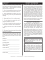
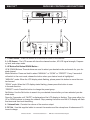
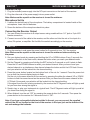
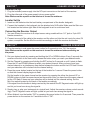
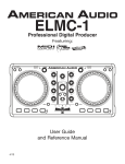
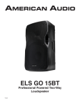
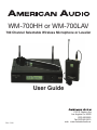
WM-700HH or WM-700LAV
700 Channel Selectable Wireless Microphone or Lavalier
User Guide
Rev. 1/08
6122 S. Eastern Ave
Los Angeles Ca. 90040
(323) 582-2650
Fax (323) 582-2610
web: www.AmericanAudio.us
WM-700™
ELECTRICAL SAFETY PRECAUTIONS
CAUTION
RISK OF ELECTRIC SHOCK
DO NOT OPEN
The lightning flash with arrowhead symbol, within an
equilateral triangle, is intended to alert the user to the
presence of uninsulated "dangerous voltage" within the
product's enclosure that may be of sufficient magnitude
to constitute a risk of electric shock to persons.
CAUTION: TO REDUCE THE RISK OF ELECTRIC
SHOCK, DO NOT REMOVE THE COVER (OR BACK).
THERE ARE NO USER SERVICEABLE PARTS
INSIDE REFER SERVICE TO YOUR AUTHORIZED
AMERICAN AUDIO® SERVICE TECHNICIAN.
The exclamation point within an equilateral triangle is
intended to alert the user to the presence of important
operating and maintenance (servicing) instructions in
the literature accompanying the appliance.
IMPORTANT SAFETY INSTRUCTIONS
REAd INSTRUCTIONS — All the safety and operating
instructions should be read before the product is
operated.
RETAIN INSTRUCTIONS — The safety and operating
instructions should be retained for future reference.
hEEd WARNINGS — All warnings on the product and
in the operating instructions should be adhered to.
FOLLOW INSTRUCTIONS — All operating and use
instructions should be followed.
CLEANING — The product should be cleaned only with
a polishing cloth or a soft dry cloth. Never clean with
furniture wax, benzine, insecticides or other volatile
liquids since they may corrode the cabinet.
ATTAChMENTS — Do not use attachments not
recommended by the product manufacturer as they
may cause hazards.
WATER ANd MOISTURE — Do not use this product
near water — for example, near a bathtub, wash
bowl, kitchen sink, or laundry tub; in a wet basement;
or near a swimming pool; and the like.
ACCESSORIES — Do not place this product on an
unstable cart, stand, tripod, bracket, or table. The
product may fall, causing serious injury to a child or
adult, and serious damage to the product. Use only
with a cart, stand, tripod, bracket, or table
recommended by the manufacturer, or sold with
the product. Any mounting of the product should
follow the manufacturer’s instructions, and should
use a mounting accessory recommended by the
manufacturer.
CART — A product and cart combination should be
moved with care. Quick stops, excessive force, and
uneven surfaces may cause the product and cart
combination to overturn.
vENTILATION — Slots and openings in the cabinet are
provided for ventilation and to ensure reliable
operation of the product and to protect it from
overheating, and these openings must not be
blocked or covered. The openings should never be
blocked by placing the product on a bed, sofa, rug,
or other similar surface. This product should not be
placed in a built-in installation such as a bookcase or
rack unless proper ventilation is provided or the
manufacturer’s instructions have been adhered to.
POWER SOURCES —This product should be operated
only from the type of power source indicated on the
marking label. If you are not sure of the type of
power supply to your home, consult your product
dealer or local power company.
LOCATION – The appliance should be installed in a
stable location.
NONUSE PERIOdS – The power cord of the appliance
should be unplugged from the outlet when left unused for a long period of time.
GROUNdING OR POLARIZATION
•
If this product is equipped with a polarized alternating
current line plug (a plug having one blade wider than
the other), it will fit into the outlet only one way. This
is a safety feature. If you are unable to insert the plug
fully into the outlet, try reversing the plug. If the plug
should still fail to fit, contact your electrician to
replace your obsolete outlet. Do not defeat the
safety purpose of the polarized plug.
•
If this product is equipped with a three-wire
grounding type plug, a plug having a third (grounding)
pin, it will only fit into a grounding type power outlet.
This is a safety feature. If you are unable to insert the
plug into the outlet, contact your electrician to
replace your obsolete outlet. Do not defeat the
safety purpose of the grounding type plug.
POWER-CORd PROTECTION - Power-supply cords
should be routed so that they are not likely to be
walked on or pinched by items placed upon or
against them, paying particular attention to cords at
plugs, convenience receptacles, and the point where
they exit from the product.
OUTdOOR ANTENNA GROUNdING — If an outside
antenna or cable system is connected to the product,
be sure the antenna or cable system is grounded so
as to provide some protection against voltage surges
and built-up static charges. Article 810 of the National
Electrical Code, ANSI/NFPA 70, provides information
with regard to proper grounding of the mast and
supporting structure, grounding of the lead-in wire
to an antenna discharge unit, size of grounding
conductors, location of antenna-discharge unit,
connection to grounding electrodes, and
requirements for the grounding electrode. See Figure
A.
LIGhTNING — For added protection for this product
during a lightning storm, or when it is left unattended
and unused for long periods of time, unplug it from
the wall outlet and disconnect the antenna or cable
system. This will prevent damage to the product
due to lightning and power-line surges.
POWER LINES — An outside antenna system should
not be located in the vicinity of overhead power lines
or other electric light or power circuits, or where it
can fall into such power lines or circuits. When
installing an outside antenna system, extreme care
should be taken to keep from touching such power
lines or circuits as contact with them might be fatal.
OvERLOAdING — Do not overload wall outlets,
extension cords, or integral convenience receptacles
as this can result in a risk of fire or electric shock.
OBJECT ANd LIQUId ENTRY - Never push objects of
any kind into this product through openings as they
may touch dangerous voltage points or short-out
parts that could result in a fire or electric shock.
Never spill liquid of any kind on the product.
SERvICING — Do not attempt to service this product
yourself as opening or removing covers may expose
you to dangerous voltage or other hazards. Refer all
servicing to qualified service personnel.
dAMAGE REQUIRING SERvICE - Unplug this product
from the wall outlet and refer servicing to qualified
service personnel under the following conditions:
•
When the power-supply cord or plug is damaged.
•
If liquid has been spilled, or objects have fallen into
the product.
•
If the product has been exposed to rain or water.
•
If the product does not operate normally by following
the operating instructions. Adjust only those controls
that are covered by the operating instructions as an
improper adjustment of other controls may result in
damage and will often require extensive work by a
qualified technician to restore the product to its
normal operation.
•
If the product has been dropped or damaged in any
way.
•
When the product exhibits a distinct change in
performance — this indicates a need for service.
REPLACEMENT PARTS -- W hen replacement parts
are required, be sure the service technician has used
replacement parts specified by the manufacturer or
have the same characteristics as the original part.
Unauthorized substitutions may result in fire, electric
shock, or other hazards.
SAFETY ChECK - Upon completion of any service or
repairs to this product, ask the service technician to
perform safety checks to determine that the product
is in proper operating condition.
WALL OR CEILING MOUNTING — The product should
not be mounted to a wall or ceiling.
hEAT — The product should be situated away from heat
sources such as radiators, heat registers, stoves, or
other products (including amplifiers) that produce
heat.
ANTENNA
LEAD IN
WIRE
GROUND
CLAMP
ANTENNA
DISCHARGE UNIT
(NEC SECTION 810-20)
ELECTRIC
SERVICE
EQUIPMENT
Fig. A
GROUNDING CONDUCTORS
(NEC SECTION 810-21)
GROUND CLAMPS
POWER SERVICE GROUNDING
ELECTRODE SYSTEM
(NEC ART 250, PART H)
NEC — NATIONAL ELECTRICAL CODE
©American
Audio® - www.americanaudio.com - WM-700™ Instruction Manual Page 2
WM-700™
I. Heat - The receiver should be situated away
from heat sources such as radiators, heat registers, stoves, or other appliances (including
amplifiers) that produce heat.
2. Do not let insecticides, benzene, or thinner
come in contact with the surface of the unit.
3. Never disassemble or modify your unit in
any way, doing so will void your manufactures
warranty.
4. Never plug this unit in to a dimmer pack
product information
Every WM-700HH™ and WM-700LAV™ has
been thoroughly tested and has been shipped
in perfect operating condition. Carefully check
the shipping carton for damage that may have
occurred during shipping. If the carton appears
to be damaged, carefully inspect your wireless microphone for any damage and be sure
all equipment necessary to operate the wireless microphone has arrived intact. In the event
damage has been found or parts are missing,
please contact our toll free customer support
number for further instructions. Please do not
return the wireless microphone to your dealer
without first contacting customer support.
5. Do not attempt to operate this unit if it
becomes damaged in any way.
6. This unit is intended for indoor use only, use
of this product outdoors voids all warranties.
7. Always mount this unit in safe and stable
matter.
8. Disconnect from main power before making
any type of connection.
The serial and model number for this unit is
located on the rear panel. Please write down
the numbers here and retain for future reference.
Model No._____________________________
Serial No._____________________________
WARRANTY INFORMATION
The WM-700HH™ and WM-700LAV™ carries
a ONE year (365 days) limited warranty. This
warranty covers parts and labor. Please fill out
the enclosed warranty card to validate your
purchase and warranty. All returned service
items whether under warranty or not, must be
freight pre-paid and accompany a return authorization (R.A.) number. If the unit is under warranty, you must provide a copy of your proof
of purchase invoice. Please contact American
Audio® customer support at (800) 322-6337 for
a R.A. number.
WARNING: TO PREVENT FIRE OR SHOCK
HAZARD, DO NOT EXPOSE THIS UNIT TO
WATER OR MOISTURE
Purchase Notes:
Date of Purchase_______________________
Dealer Name__________________________
Dealer Address_________________________
_____________________________________
_____________________________________
NOTE: This product satisfies FCC regulations
when shielded cables and connectors are
used to connect the unit to other equipment.
To prevent electromagnetic interference with
electrical appliances such as radios and televisions, use shielded cables and connectors
for connections.
Dealer Phone__________________________
©American
Audio® - www.americanaudio.com - WM-700™ Instruction Manual Page 3
WM-700™
introduction
Introductions: Congratulations and thank you for purchasing the American Audio® WM-700HH™ or
WM-700LAV™. These wireless systems are a representation of American Audio’s continuing commitment to produce the best and highest quality audio products possible at an affordable price. Please
read and understand this manual completely before attempting to operate your new wireless microphone. Please carefully read and understand the instructions in this manual thoroughly before attempting to operate this unit. These instructions contain important safety information regarding the use and
maintenance of this unit. Take special care to follow all warning symbols and labels both on the unit
and printed in this manual. Also, Please keep this manual with the unit, for future reference.
Customer Support:
American Audio® provides a toll free customer support line, to provide set up help and answer any
question should you encounter problems during your initial set up or operation. You may also visit us
on the web at www.americanaudio.com for any comments or suggestions. Service Hours are Monday
through Friday 9:00 a.m. to 5:30 p.m. Pacific Standard Time.
Voice:
(800) 322-6337
Fax: (323) 582-2941
E-mail: [email protected]
To purchase parts online visit http://parts.americandj.com
Caution! There are no user serviceable parts inside the receiver and microphone or lavalier. Do not
attempt any repairs yourself, without being instructed to do so by an authorized American Audio service technician. Doing so will void your manufactures warranty. In the unlikely event your microphone
or receiver may require service, please contact American Audio® customer support.
Do not discard the packing carton in the trash. Please recycle when ever possible.
WM-700™
set up precautions
Please be sure to make any connections before plugging the receiver in to an electrical outlet. Volume
control should be set to zero or minimum position, before the receiver is switched on. If the receiver
has been exposed to drastic temperature fluctuation (e.g. after transportation), do not switch on the
receiver immediately. The arising condensation of water might damage your device. Leave the device
switched off until it has reached room temperature.
Operating Determinations:
• When installing this unit, please make sure that the device is not exposed or will not be
exposed to extreme heat, moisture or dust!
• Do not operate the unit in extremely hot (more than 30°/100°F) or extremely cold (less than
5°C/40°F) surroundings.
• Keep the unit out of direct sunlight and away from heaters.
• Operate the unit only after becoming familiar with its functions. Do not permit operation by
persons not qualified for operating the unit. Most damages are the result of unprofessional
operation!
• Do not attempt to operate this unit if the power cord has been frayed or damaged.
• Disconnect from main power before making any type of connection.
• Do not attempt to operate this unit, if it becomes damaged in any way.
• Never operate this unit when it’s covers are removed.
• To reduce the risk of electrical shock or fire, do not expose this unit to rain or moisture.
• This unit is intended for indoor use only, use of this product outdoors voids all warranties.
• During long periods of non-use, disconnect the unit’s main power.
©American
Audio® - www.americanaudio.com - WM-700™ Instruction Manual Page 4
WM-700™
Receiver CONTROLS AND FUNCTIONS
CH
POWER
GP
P1 P2 P3 P4
MANUAL
CH
C1 C2 C3 C4 C5 C6 C7 C8
FREQ
SCAN
SET
MHz
PRESET
RF
AF
VOLUME
DC OUT
1
2
3
4
5
AUDIO OUTPUT
UNBALANCED
LINE
SQUELCH
DC ONLY
12V 500mA
8
7
MIC
BALANCED
6
11
10
9
6
1. Power Button - Press this button for 4 seconds to turns On the receiver.
2. LCD Screen - The LCD screen will show the channel number, AF & RF signal strength, Frequen- cy level, and setup mode.
3. UP Button/Set Button/DOWN Button UP & DOWN Buttons: These buttons are used to select your desired mode, and search for your desired channel.
Mode Selection: Press and hold to select “MANUAL” or “SCAN” or “PRESET”. Every 2 seconds it
will switch to the next mode, release the button when your desired mode is highlighted.
“MANUAL” mode: When the LCD display starts flashing, please press this button to move the number forward.
“SCAN” mode: When the LCD display starts flashing, please press this button to scan
in forward direction.
“PRESET” mode: Press this button to change the preset group.
Set Button: Use the Set button to search for your desired channel after you have selected your desired mode.
Press for 2 seconds, until “MUTE” is displayed and the LCD display is flashing. Then press either the
UP or DOWN buttons to change the channel. Stop pressing the button and the LCD display will flash
five times and then lock the setting.
4. Volume Knob - Controls the volume of the receiver output.
5. DC Out - Use this supplied cable to connect the receiver and the microphone. It takes around 10
hours to charge.
©American
Audio® - www.americanaudio.com - WM-700™ Instruction Manual Page 5
WM-700™
Receiver CONTROLS AND FUNCTIONS Cont.
6. Antennas - Receives RF signals from the transmitter.
7. 12v DC Input - Connect the included power supply to this input, or any other 12v power adapter.
8. Squelch Adjustment - The squelch adjusts the output level to prevent external noise. If you set
the squelch to high you will reduce the range of the system. Set the squelch to a minimum before
turning the receiver on.
9. Mic/Line Switch - This switch lets you select your output source. If your connected to the line
input on a mixer or amplifier set the switch to “Line”. If your connected to a Mic input on a mixer or
amplifier set the switch to “Mic”.
10. Unbalanced 1/4” Output - This unbalanced output can be used to connect the receiver to the
line-level input of a mixer or amplifier.
11. Balanced XLR Output - This balanced XLR output can be used to connect the receiver to balanced input of mixer or amplifier.
WM-700™
Receiver Modes
Manual Mode: In manual mode you can set your desired channel manually.
1. Select manual mode by pressing and holding either the UP or DOWN buttons until MANUAL is highlighted in the LCD.
2. Press the SET button for 2 seconds. The LCD will start to flash and “MUTE” will appear in the LCD.
3. Press the UP and DOWN buttons to find your desired channel or an interference free channel. After you have found your channel release the button and let the LCD flash 5 times and you selection will be locked into the channel setting.
Auto-Scan (Scan) Mode: In Scan mode you can let the receiver scan to for a clear channel.
1. Select auto-scan mode by pressing and holding either the UP or DOWN buttons until Scan is highlighted in the LCD.
2. Press the SET button for 2 seconds. The LCD will start to flash and “MUTE” will appear in the LCD.
3. Press the UP and DOWN buttons to find your desired channel or an interference free channel. After you have found your channel release the button and let the LCD flash 5 times and your selection will be locked into the channel setting.
Preset Mode: In Preset mode you can select a Preset channel that is pre-programmed into the receiver. There are 4 Preset groups with 8 default channels in each group. Each of the 8 default channels are different in each of the 4 Preset groups.
1. Select Preset mode by pressing and holding either the UP or DOWN buttons until Preset is high- lighted in the LCD.
2. Press the SET button for 2 seconds. The LCD will start to flash and “MUTE” will appear in the LCD.
3. Use the UP button to scroll through the 4 Preset groups, and use the DOWN button to scroll through the 8 default channels in each Preset group. After you have found your desired channel or an interference free channel release the button and let the LCD flash 5 times and you selection will be locked into the channel setting.
©American
Audio® - www.americanaudio.com - WM-700™ Instruction Manual Page 6
WM-700™
Receiver Set Up
Microphone System Set up
1. Plug the included power supply into the DC input connector on the back of the receiver.
2. Plug the other end of the power supply into an power outlet.
Note: Make sure the squelch on the receiver is turned the minimum.
Microphone Set Up
1. Unscrew the bottom part of the microphone. The battery compartment is located inside of the microphone. Insert two AA batteries.
2. Screw the bottom of the microphone back into place.
Connecting the Receiver Output
1. You can connect the receiver to a output source using a cable with an 1/4’’ jack or 3-pin XLR
female connection.
2. Connect one end of the cable to the receiver, and the other end into the mic or line input of a mixer, PA system, or amplifier. Set the Mic/Line switch accordingly on the receiver.
WM-700™
Mic System operation
1. Plug the receiver in and press the power button for 2 seconds to turn “On” the receiver.
Note: Make sure the squelch on the receiver is turned the minimum before switching on the power.
2. Set your desired mode by pressing and holding the UP or DOWN buttons. Every 2 seconds the receiver will switch to the next mode, release the button when you reach your desired mode.
3. Set the Channel by pressing and holding the SET button for 3 seconds or until it starts to flash.
Press the UP and DOWN buttons to select your desired channel. After you have found your desired channel or an interference free channel release the button and let the LCD flash 5 times
and you selection will be locked into the channel setting.
4. Press the power button located on the bottom front of the mic for 1 second. Press the power but-
ton so that the channel display begins to flash.
Set the mic to the same channel as the receiver by pressing the either the channel UP or DOWN buttons to find the same channel as the receiver. After you have found the same channel let the LCD flash 5 times and your selection will be locked into the channel setting.
If the signal from the mic is being received by the receiver the RF Segment meter will light up and let you know how strong the signal is.
5. Speak, sing, or play your instrument at a typical level. The AF Segment meter will light up and let you know how strong the signal is.
6. When finished, turn the mic “Off” by pressing the power button for 2 seconds. Then press the power button on the receiver for 2 seconds to turn it “Off”.
Note: If you have rechargable batteries installed in the mic, you can connect the supplied
cable to the DC out located on the front of the receiver to the input jack on the bottom of the
mic and recharge the batteries.
©American
Audio® - www.americanaudio.com - WM-700™ Instruction Manual Page 7
WM-700™
Receiver Set Up
Lavalier System Set up
1. Plug the included power supply into the DC input connector on the back of the receiver.
2. Plug the other end of the power supply into an power outlet.
Note: Make sure the squelch on the receiver is turned the minimum.
Lavalier Set Up
1. Insert two AA batteries into the back battery compartment of the lavalier bodypack.
2. Connect the headset to the bodypack via the attached mini XLR cable. Make sure the Gain con-
trol located on the bottom right side of the bodypack is set to a minimum level.
Connecting the Receiver Output
1. You can connect the receiver to a output source using a cable with an 1/4’’ jack or 3-pin XLR
female connection.
2. Connect one end of the cable to the receiver, and the other end into the mic input of a mixer, PA system, or amplifier. Set the Mic/Line switch accordingly on both the receiver and lavalier.
WM-700™
Lavalier operation
1. Plug the receiver in and press the power button for 2 seconds to turn “On” the receiver.
Note: Make sure the squelch on the receiver is turned the minimum before switching on the power.
2. Set your desired mode by pressing and holding the UP or DOWN buttons. Every 2 seconds the receiver will switch to the next mode, release the button when you reach your desired mode.
3. Set the Channel by pressing and holding the SET button for 3 seconds or until it starts to flash.
Press the UP and DOWN buttons to select your desired channel. After you have found your desired channel or an interference free channel release the button and let the LCD flash 5 times
and your selection will be locked into the channel setting.
4. Press the power button located on the top of the lavalier for 1 second. Press the power button so that the channel display begins to flash.
Set the lavalier to the same channel as the receiver by pressing the either the channel UP or DOWN buttons to find the same channel as the receiver. After you have found the same channel let the LCD flash 5 times and your selection will be locked into the channel setting. Set the
Mic/Line switch located on the back of the lavalier accordingly.
If the signal from the lavalier is being received by the receiver the RF Segment meter will light up and let you know how strong the signal is.
5. Speak, sing, or play your instrument at a typical level. Adjust the receiver volume control accord- ingly. The AF Segment meter will light up and let you know how strong the signal is.
6. When finished, turn the lavalier “Off” by pressing the power button for 2 seconds. Then press the power button on the receiver for 2 seconds to turn it “Off”.
WM-700™
Trouble shooting
Trouble Shooting: Listed below are common problems you may encounter, and their solutions.
There is no power to the unit:
1. Make sure you have connected the power cord to a 120v wall outlet.
There is little or no sound:
1. Make sure the battery is inserted properly (+/- battery terminals must match transmitter termi
nals).
2. Move transmitter closer to the receiver.
3. Is the low battery LED lit? If so replace the battery.
4. Make sure the receiver volume is not turned all the way down.
5. Check the cable connection between receiver and amplifier or mixer.
There is a momentary loss of sound when the transmitter is moved around the area:
1. Move the receiver around a perform walk-through tests. If audio dropouts continue, mark the
“dead” areas and avoid the during performance.
Radio signals are interrupting performance:
1. Change the frequency channels on both the transmitter and receiver.
©American
Audio® - www.americanaudio.com - WM-700™ Instruction Manual Page 8
Warranty
1-YEAR LIMITED WARRANTY
A. American Audio® hereby warrants, to the original purchaser, American Audio® products to
be free of manufacturing defects in material and workmanship for a period of 1 Year (365 days)
from the date of purchase. This warranty shall be valid only if the product is purchased within the
United States of America, including possessions and territories. It is the owner’s responsibility to
establish the date and place of purchase by acceptable evidence, at the time service is sought.
B. For warranty service, send the product only to the American Audio® factory. All shipping
charges must be pre-paid. If the requested repairs or service (including parts replacement) are
within the terms of this warranty, American Audio® will pay return shipping charges only to a
designated point within the United States. If the entire instrument is sent, it must be shipped
in its original package. No accessories should be shipped with the product. If any accessories
are shipped with the product, American Audio® shall have no liability whatsoever for loss of
or damage to any such acces-sories, nor for the safe return thereof. C. This warranty is void if the serial number has been altered or removed; if the product is
modified in any manner which American Audio® concludes, after inspection, affects the reliability of the product; if the product has been repaired or serviced by anyone other than the
American Audio® factory unless prior written authorization was issued to purchaser by American Audio®; if the product is damaged because not properly maintained as set forth in the
instruction manual.
D. This is not a service contract, and this warranty does not include maintenance, cleaning
or periodic check-up. During the period specified above, American Audio® will replace defective parts at its expense, and will absorb all expenses for warranty service and repair labor by
reason of defects in material or workmanship. The sole responsibility of American Audio®under
this warranty shall be limited to the repair of the product, or replacement thereof, including
parts, at the sole discretion of American Audio®. All products covered by this warranty were
manufactured after January 1, 1990, and bear identifying marks to that effect.
E. American Audio® reserves the right to make changes in design and/or improvements upon
its products without any obligation to include these changes in any products theretofore manufactured.
F. No warranty, whether expressed or implied, is given or made with respect to any accessory supplied with products described above. Except to the extent prohibited by applicable
law, all implied warranties made by American Audio® in connection with this product, including
warranties of merchantability or fitness, are limited in duration to the warranty period set forth
above. And no warranties, whether expressed or implied, including warranties of merchantability or fitness, shall apply to this product after said period has expired. The consumer’s and
or Dealer’s sole remedy shall be such repair or replacement as is expressly provided above;
and under no circumstances shall American Audio® be liable for any loss or damage, direct or
consequential,
arising out of the use of, or inability to use, this product.
G. This warranty is the only written warranty applicable to American Audio® Products and supersedes all prior warranties and written descriptions of warranty terms and conditions heretofore published.
©American
Audio® - www.americanaudio.com - WM-700™ Instruction Manual Page 9
SPECIFICATIONS
GENERAL
System:
Dimensions: Installation:
Weight:
Power supply:
Model: American Audio® WM-700HH and WM-700LAV
700 Channel UHF Wireless Microphone or Lavalier System
Receiver:
1.73” H x 7.09” W x 8.31” L
Place on flat surface or mount in flat case
Mic & Receiver:
1.52 Lbs. / .69 kgs
Bodypack, Lavalier, & Receiver:
1.3lbs / 0.59 Kgs. DC 12V - 18V / For Receiver
Environmental conditions: Operational temperature:
5 to 35˚C (41 to 95˚F) Operational humidity:25 to 85% RH (non-condensation) Storage temperature:-20 to 60˚C (4 to 140˚F)
RECEIVER:
Frequency Stability:
+ 0.005%
Receiving Sensitivity:
At 5 µ V over 80dB S/N ratio
Image & Spurious Rejection:80dB minimum
Selectivity:
> 50dB
Tone Signal:
32.768KHz
S/N ratio:
> 94dB, at 48KHz deviation and 60dB µ V antenna input
AF Response:
50Hz to 15KHz
T.H.D. Rate:
Less than 1.0% (at 1KHz)
Audio Output:
Balanced and Unbalanced outputs
Power supply:
DC 12V - 18V
Current Consumption:
110mA ± 10mA
Mic/Bodypack Transmitter:
RF Power Output:
10mW (max)
Frequency stability:
+0.005%
T.H.D. rate:
< 1% (at 1KHz)
Oscillation mode:
PLL synthesized, 700 Channel selectable
Spurious Emission:
> 60dB below carrier frequency
Maximum Deviation:
+ 48KHz with limiting compressor
Current consumption:
110mA at 3V
Battery:
DC3V (2 x 1.5V AA batteries) or DC2.4V (2 x 1.2V AA rechargeable batteries)
Tone Signal:
32.768KHz
NOTES:
The specifications are subject to change to any improvement by negotiations in advance.
The parts are subject to change to any improvement within the range of the specifications.
©American Audio® World Headquarters:
6122 S. Eastern Ave. Los Angeles, CA 90040 USA
Tel: 323-582-3322 Fax: 323-582-3311
Web: www.americanaudio.us E-mail: [email protected]