1
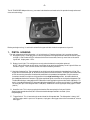
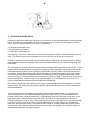
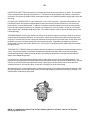
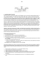
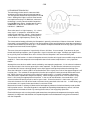
ULTRAPROBETM 100
INSTRUCTION MANUAL
VOLUME 1.3
NEED HELP???
HAVE QUESTIONS??
AT UE SYSTEMS, WE ARE DEDICATED TO SUPPORTING OUR
ULTRAPROBE USERS.
OUR STAFF HAS YEARS OF FIELD EXPERIENCE AND IS
STANDING READY Alpine
TO ASSIST
YOU SHOULD YOU NEED US.
Components
WHEREVER
YOU
ARE,
REMEMBER,
WE ARE AS CLOSE AS YOUR
Telephone:
01424
437000
E-mail: [email protected]
PHONE,
FAX
OR
COMPUTER.
Fax: 01424 722502 Web site: www.alpine-components.co.uk
CALL: 914-592-1220
FAX: 914-347-2181
Email: [email protected]
Internet: http://www.uesystems.com
-1The ULTRAPROBE 100 provides easy, accurate leak detection and mechanical inspection through advanced
ultrasonic technology.
kit shot
Before you begin testing, it is advisable to familiarize yourself with the basic components of your kit.
1.
PISTOL HOUSING
The main component of the Ultraprobe is its' pistol housing. From back to front, let's examine each part.
A. Bargraph Display: The display consists of a ten segment LED bargraph that will indicate ultrasonic signal
strength. A low number of LEDs indicate a low level of ultrasound, conversly more intense ultrasonic
signals will display more LEDs.
B. Battery Level Light: This red light turns on only when the batteries need to be replaced.
NOTE: When the trigger on/off switch is pulled to the on position the Battery Level Light will flicker on
and then stay off. This is normal and has no relation to battery condition.
C. Sensitivity Selection Dial: There are eight (8) sensitivity levels which read out in related decibels of "0" to "70".
As the dial is turned to the right, to "0", the sensitivity of the instrument increases. As the dial is turned to the left ,
to "70", the sensitivty decreases. A low level ultrasound emission produces low amplitude. For this reason, the
instrument should be in a high sensitivity position. 0 is the high sensitivity position. 0 is a dB indication of
threshold detection for the instrument. For higher amplitude signals, move the sensitivity to the left towards "70".
The dial dB indications, along with the LED indications in the bar graph may be used to establish dB levels. To
do this, just add 3 dB for each LED bargraph indication to the dB level set in the sensitivity dial. EX: 0 dB on the
sensitivity dial, plus 3 LED bargrah levels = 9dB (0+9). 40 dB on the sensitivity dial plus 4 bar graphs = 52 dB
(40+12)
D. Head Set Jack: This is where you plug in the headset. Be sure to plug it in firmly until it clicks.
Should a tape recorder be utilized, this is where the cord for the tape recorder is inserted. (Use a
miniphone plug).
E. Trigger Switch: This is located on the underside of the Ultraprobe 100. The Ultraprobe is always "off"
until the trigger switch is pressed. To operate, simply press the trigger; to turn the instrument off, release
the trigger.
-2-
2.
SCANNING MODULE
This module is utilized to receive air-borne ultrasound such as
the ultrasounds emitted by pressure leaks and electrical discharges.
To use, make sure it is plugged in to the front end of the metered
pistol housing by aligning the plug with the receptical and inserting
it firmly.
To use the Scanning Module:
1. Plug in to front end.
2. Start with the sensitivity selection dial at maximum (8).
Scanning Module
3. Start to scan the test area.
a. The method of air borne detection is to go from the "gross to the fine". If there is too much
ultrasound in the area, reduce the sensitivity, place the RUBBER FOCUSING PROBE (described
below) over the scanning module and proceed to follow the test sound to its' loudest point. If it is difficult to
locate the sound due to a high intensity signal, keep reducing the sensitivity and following the meter to the
loudest point.
RUBBER FOCUSING PROBE: The Rubber Focusing Probe is a circular shaped rubber shield. It is used to
block out stray ultrasound and to assist in narrowing the field of reception of the Scanning Module. It also
increases the sensitivity. To use, simply slip it over the front of the scanning module or the contact module.
NOTE: To prevent damage to the module plug, always remove the module BEFORE attaching and removing the
Rubber Focusing Probe.
3.
CONTACT (STETHOSCOPE) MODULE
This is the module with the metal rod. This rod is utilized as a
"wave-guide" that is sensitive to ultrasound generated internally such as
within a pipe, bearing housing, steam trap or wall. Once stimulated by
ultrasound, it transfers the signal to a piezoelectric transducer located
directly in the module housing.
To use the Stethoscope Module:
1. Align the pin located at the rear of the module with the jack in
the front end of the Metered Pistol Housing and plug in firmly.
2. Touch test area.
3. As with the scanning module, go from the "gross" to the "fine". Start a
maximum sensitivity on the Sensitivity Selection Dial and proceed to
reduce the sensitivity until a satisfactory sound and meter level is
achieved.
Contact Module
-34. HEADSET
This heavy duty headset is designed to block out intense sounds often found in industrial environments so that
the user may easily hear the sounds received by the ULTRAPROBE. To use, simply plug the headset cord into the
headset jack on the metered pistol housing, and place the headphones over your ears. If a hard hat is to be worn, it
is recommended to use UE Systems' model UE-DHC-2HH Hard Hat Headphones which are specifically
designed for hard hat use.
A. For those situations in which it is not possible or difficult to wear the standard headphones
described above, UE Systems has two options available: 1. the DHC 1991 Earpiece which loops
around the ear, and 2. the SA-2000 Speaker Amplifier which is a loud speaker that is compatible
with the Ultraprobe headphone output jack.
5.
WTG-1 WARBLE TONE GENERATOR (OPTION)
The WTG-1 Tone Generator is an ultrasonic transmitter designed to flood an area with ultrasound. It is used for a
special type of leak test. When placed inside an empty container or on one side of a test item, it will flood that area
with an intense ultrasound that will not penetrate any solid but will flow through any existing fault or void. By
scanning with the Scanning Module, empty containers such as pipes, tanks, windows, doors, bulkheads or hatches
can be instantly checked for leakage. This Tone Generator is a WARBLE TONE GENERATOR. This internationally patented transmitter sweeps through a number of ultrasonic frequencies in a fraction of a second to produce a
strong, recognizable "Warble" signal. The warble tone prevents a standing wave condition which can produce false
readings and provides for a consistency of testing in practically any material.
To use the WARBLE TONE GENERATOR:
1. Turn Tone Generator on by selecting either "LOW" for a low amplitude signal (usually recommended for
small containers) or "HIGH" for high amplitude. In high, the Warble Tone Generator will cover up to
4,000 cubic feet (121.9 cu. meters) of unobstructed space.
When the Tone Generator is on, a red light (located below the recharge jack in the front) flickers.
2. Place the Warble Tone Generator within the test item/container and seal or close it. Then scan the
suspect areas with the Scanning Module in the Ultraprobe and listen for where the "warble"
ultrasound penetrates.
As an example, if the item to be tested is the seal around a window, place the Warble Tone Generator
on one side of the window, close it and proceed to scan on the opposite side.
To test the condition of the Warble Tone Generator battery, set to the LOW INTENSITY position and
listen to the sound through the Ultraprobe headphones. A smooth continuous warbling sound should be heard.
If a "beeping" is heard instead, then a full recharge of the Warble Tone Generator is indicated.
To charge the Warble Tone Generator:
1. Use the recharger.
2. Plug the recharger cord into the recharge jack located on
top of the front panel.
3. Plug the recharger into the local current supply
4. A complete charge will take 7 hours.
5. Since there is no memory problem, the Tone Generator
may be charged after short intervals of use.
WTG1 WARBLE TONE
GENERATOR (OPTIONAL)
-4-
ULTRAPROBE APPLICATIONS
1.
LEAK DETECTION
This section will cover airborne leak detection of pressure and vacuum systems. (For information concerned
with internal leaks such as in Valves and Steam Traps, refer to the appropriate sections).
What produces ultrasound in a leak? When a gas passes through a restricted orifice under pressure, it is going from
a pressurized laminar flow to low pressure turbulent flow. (Fig. 1). The turbulence generates a broad spectrum of
sound called "white noise". There are ultrasonic components in this white noise. Since the ultrasound will be
loudest by the leak site, the detection of these signals is usually quite simple.
PRESSURE LEAK
FIGURE 1
VACUUM LEAK
FIGURE 2
A leak can be in a pressurized system or in a vacuum system. In both instances, the ultrasound will be produced in
the manner described above. The only difference between the two is that a vacuum leak will usually generate less
ultrasonic amplitude than a pressure leak of the same flow rate. The reason for this is that the turbulence produced
by a vacuum leak is occuring within the vacuum chamber while the turbulence of a pressure leak is generated in the
atmosphere. (Fig.2).
What type of gas leak will be detected ultrasonically? Generally any gas, including air, will produce a turbulence
when it escapes through a restricted orifice. Unlike gas specific sensors, the Ultraprobe is sound specific. A gas
specific sensor is limited to the particular gas it was designed to sense (e.g., helium). The Ultraprobe can sense any
type of gas leak since it detects the ultrasound produced by the turbulence of a leak.
Because of its versatility, the Ultraprobe may be utilized in a wide variety of leak detection. Pneumatic systems
may be checked, pressurized cables, such as those utilized by telephone companies, may be tested. Air brake
systems on railroad cars, trucks, and buses may be checked. Tanks, pipes, housings, casings and tubes are easily
tested for leakage by pressurizing them. Vacuum systems, turbine exhausts, vacuum chambers, material handling
systems, condensers, oxygen systems can all easily be tested for leakage by listening for the turbulence of the leak.
A. HOW TO LOCATE LEAKS
1. Use the SCANNING MODULE.
2. Start off with the sensitivity selection at 0 (Maximum).
3. Begin to scan by pointing the module towards the test area. The procedure is to go from the "gross" to
the "fine" - more and more subtle adjustments will be made as the leak is approached.
4. If there is too much ultrasound in the area, reduce the sensitivity setting and continue to scan.
5. If it is difficult to isolate the leak due to competing ultrasound, place the RUBBER FOCUSING PROBE
over the scanning module and proceed to scan the test area.
6. Listen for a "rushing" sound while observing the meter.
7. Follow the sound to the loudest point. The meter will show a higher reading as the leak is approached.
8. In order to focus in on the leak, keep reducing the sensitivity setting and move the instrument closer to
the suspected leak site until you are able to confirm a leak.
-5-
B. TO CONFIRM A LEAK:
Position the Scanning Module, or the rubber focusing probe (if it is on the scanning module) close to the
suspect leak site and move it, slightly, back and forth, in all directions. If the leak is at this location, the sound will
increase and decrease in intensity as you sweep over it. In some instances, it is useful to position the rubber focusing
probe directly over the suspect leak site and push down to "seal" it from surrounding sounds. If it is the leak, the
rushing sound will continue. If it is not the leak site, the sound will drop off.
C.
OVERCOMING DIFFICULTIES
1. Competing Ultrasounds
If competing ultrasounds make it difficult to isolate a leak, there are two approaches to be taken:
a. Manipulate the environment. This procedure is fairly straight forward. When possible, turn off
the equipment that is producing the competing ultrasound or isolate the area by closing a
door or window.
b. Manipulate the instrument and use shielding techniques. If environmental manipulation is not
possible, try to get as close to the test site as possible, and manipulate the instrument so that
it is pointing away from the competing ultrasound. Isolate the leak area by reducing the sensitivity of the
unit and by pushing the tip of the rubber focusing probe up to the test area, checking a small section at a
time.
1. SHIELDING TECHNIQUES
Since ultrasound is a high frequency, short wave signal, it can usually be blocked or "shielded". NOTE: When
using any method, be sure to follow your plant's or company's safety guidelines. Some common techniques are:
a. Body: place your body between the test area and the competing sounds to act as a barrier
b. Clip Board: Position the clip board close to the leak area and angle it so that it acts as a
barrier between the test area and the competing sounds
c. Gloved Hand: (USE CAUTION) using a gloved hand, wrap the hand around the rubber
focusing probe tip so that the index finger and the thumb are close to the very end and place the rest of the
hand on the test site so that there is a complete barrier of the hand between the test area and the background
noise. Move the hand and instrument together over the various test zones.
d. Wipe rag: This is the same method as the "gloved hand" method, only, in addition to the
glove, use a wipe rag to wrap around the rubber focusing probe tip. Hold the rag in the gloved hand so that it
acts as a "curtain", i.e., there is enough material to cover the test site without blocking the open end of the
rubber focusing probe. This is ususally the most effective method since it uses three barriers: the rubber
focusing probe, the gloved hand and the rag.
e. Barrier: When covering a large area, it is sometimes helpful to use some reflective material, such as a
welders curtain or a drop cloth, to act as a barrier. Place the material so that it acts as a "wall" between the test
area and the competing sounds. Sometimes the barrier is draped from ceiling to floor, at other times, it is
hung over railings.
-6D. LOW LEVEL LEAKS
In ultrasonic inspection of leakage, the amplitude of the sound often depends upon the amount of turbulence
generated at the leak site. The greater the turbulence, the louder the signal, the less the turbulence, the lower the
intensity of the signal. When a leak rate is so low that it produces little, if any turbulence that is "detectable", it is
considered "below threshold". If a leak appears to be of this nature:
1.
Build up the pressure (if possible) to create greater turbulence.
2.
Utilize LIQUID LEAK AMPLIFIER.
This patented method incorporates a UE Systems product called LIQUID LEAK AMPLIFIER, or LLA for
short. LLA is a uniquely formulated liquid substance that has special chemical properties. Used as an ultrasonic "bubble test, a small amount of LLA is poured over a suspected leak site. It produces a thin film through
which the escaping gas will pass. When it comes in contact with a low flow of gas, it quickly forms a
large number of small "soda-like" bubbles that burst as soon as they form. This bursting effect produces
an ultrasonic shock wave that is heard as a crackling sound in the headphones. In many instances the
bubbles will not be seen, but they will be heard. This method is capable of obtaining successful leak
checks in systems with leaks as low as 1x10⁻⁶ ml/sec.
NOTE: The low surface tension of the LLA is the reason small bubbles form. This can be negatively changed
by contamination of the leak site with another leak fluid which can block LLA or cause large bubbles to form.
If contaminated, clean the leak site with water, solvent or alcohol (check with plant regulations before
selecting a decontaminating cleaning agent).
LLA
E. TONE TEST (Ultratone )
The Tone Test is an ultrasonic method for non-destructive testing which is used when it is difficult to pressurize
or draw a vacuum in a system. This ultrasonic test is applicable to a wide range of items, including:
CONTAINERS, TUBES, PIPES, HEAT EXCHANGERS, WELDS , GASKETS, SEALS, DOORS, WINDOWS,
OR HATCHES.
The test is conducted by placing an ultrasonic transmitter, called TONE GENERATOR, inside (or on one side) of
the test item. The warble pulse-signal from the TONE GENERATOR will instantly "flood" the test item and
penetrate any existing leak hole. Depending on configuration and material, even thin spots in certain metals can be
vibrated by the signal. By scanning for sonic penetration on the exterior surface (or opposite side) of the test item
with the Ultraprobe, the leak will be detected. It will be heard as a high pitched warble, similar to bird chirping.
-7The Tone Test incorporates two basic components: a TONE GENERATOR (an ultrasonic transmitter) , and the
Scanning Module in the Ultraprobe. To conduct the test:
1. Make certain the test item has no fluids or contaminants such as water, mud, sludge, etc., that can block the path
of the transmitted ultrasound.
2. Place the Tone Generator within the container, (if it is a room, door or window to be tested, place the Tone
Generator on one side pointing in the direction of the area to be tested) and close, or seal so that the Tone Generator is enclosed within.
NOTE: The size of the test area will determine the amplitude selection of the Tone Generator. If the item to be
tested is small, select the LOW position. For larger items, use the HIGH position.
3. Scan the test area with the Ultraprobe as outlined in LEAK DETECTION procedure. (i.e., start with the
sensitivity selection at 8 and proceed down).
When positioning the Tone Generator, place the transducer facing and close to the most crucial test area. If a
general area is to be checked, position the Tone Generator so that it will cover as wide an area as possible by placing
it in the "middle" of the test item.
How far will the sound travel? The Tone Generator is designed to cover approximately 4000 cubic feet (1219 cu
meters) of uninterrupted space. This is slightly larger than the size of a tractor trailer. Placement is dependent
upon such variables as the size of the leak to be tested, the thickness of the test wall and the type of material tested
(i.e. is it sound absorbant or sound reflective?). Remember, you are dealing with a high frequency, short wave
signal. If the sound is expected to travel through a thick wall, place the Tone Generator close to the test zone, if it
is a thin metallic wall, move it farther back and use "low". For uneven surfaces it may be necessary to use two
people. One person will move the Tone Generator slowly close to and around the test areas while another person
scans with the Ultraprobe on the other side.
Do not use the Tone test in a complete vacuum.
Ultrasound will not travel in a vacuum. Sound waves need molecules to vibrate and conduct the signal. There are
no moveable molecules in a complete vacuum.
If a partial vacuum is to be drawn where there are still some air molecules to vibrate, then the Tone Test may be
implemented successfully.
In a laboratory, a form of the Tone Test is utilized in seal leaks of an electron beam microscope. The test chamber
has been fitted with a specially designed transducer to emit the desired tone and a partial vacuum is created. A user
then scans all seams for sonic penetration. The Tone Test has also been effectively utilized to test tanks before they
are put on line, piping, refrigerator gaskets, caulking around doors and windows for air infiltration testing, heat
exchangers for leaking tubes, as a Q.C. test for automobile wind noise and water leaks, on aircraft to test for
problems associated with cabin pressure leaks and glove boxes for seal integrity defects.
Optional
Pipe Threaded
Tone Generator
UE-WTG2SP
-82.
ELECTRIC ARC, CORONA, TRACKING DETECTION
There are three basic electrical problems that are detected with the Ultraprobe 500:
Arcing: An arc occurs when electricity flows through space. Lightning is a good example.
Corona: When voltage on an electrical conductor, such as an antenna or high voltage
transmission line exceeds the threshold value, the air around it begins to ionize to form a
blue or purple glow.
Tracking: Often refered to as "baby arcing", follows the path of damaged insulation.
Although theoretically the Ultraprobe 100 can be used in low, medium and high voltage systems, most of the
applications tend to be in medium and high voltage systems.
When electricity escapes in high voltage lines or when it "jumps" across a gap in an electrical connection, it disturbs
the air molecules around it and generates ultrasound. Most often this sound will be perceived as a crackling or
"frying" sound, in other situations it will be heard as a buzzing sound.
Typical applications include: insulators, cable, switchgear, buss bars, relays, contactors, junction boxes. In substations, components such as insulators, transformers and bushings may be tested.
Ultrasonic testing is often used at voltages exceeding 2,000 volts, especially in enclosed switchgear. Since ultrasound emissions can be detected by scanning around door seams and air vents, it is possible to detect serious faults
such as arcing, tracking and corona without taking the switchgear off line to perform an infrared scan. However, it
is recommended that both tests be used with enclosed switchgear.
NOTE: When testing electrical equipment, follow all your plant or company safety procedures. When
in doubt, ask your supervisor. Never touch live electrical apparatus with the Ultraprobe.
The method for detecting electric arc and corona leakage is similar to the procedure outlined in leak detection.
Instead of listening for a rushing sound, a user will listen for a crackling or buzzing sound. In some instances, as in
trying to locate the source of radio/TV interference or in substations, the general area of disturbance may be located
with a gross detector such as a transistor radio or a wide-band interference locator. Once the general area has been
located, the scanning module of the Ultraprobe is utilized with a general scan of the area. The sensitivity is reduced if the signal is too strong to follow. When this occurs, reduce the sensitivity to get a mid-line reading on the
meter and continue following the sound until the loudest point is located.
Determining whether a problem exists or not is relatively simple. By comparing sound quality and sound levels
among similar equipment, the problem sound will tend to be quite different.
On lower voltage systems, a quick scan of bus bars often will pick up a loose connection. Checking junction boxes
can reveal arcing. As with leak detection, the closer one gets to the emission site, the louder the signal.
Test switchgear, transformers, etc.
for arcing, tracking & corona.
-9-
bearing shot
3.
DETECTING BEARING WEAR
Ultrasonic inspection and monitoring of bearings is by far the most reliable method for detecting incipient bearing
failure. The ultrasonic warning appears prior to a rise in temperature or an increase in low frequency vibration
levels. Ultrasonic inspection of bearings is useful in recognizing:
a. The beginning of fatigue failure.
b. Brinelling of bearing surfaces.
c. Flooding of or lack of lubricant.
In ball bearings, as the metal in the raceway, roller or ball bearing begins to fatigue, a subtle deformation begins to
occur. This deforming of the metal will produce an increase in the emission of ultrasonic sound waves.
Changes in amplitude of from 12 to 50 times the original reading is indication of incipient bearing failure. When a
reading exceeds any previous reading by 12 db, it can be assumed that the bearing has entered the beginning of the
failure mode.
This information was originally discovered through experimentation performed by NASA on ball bearings. In tests
performed while monitoring bearings at frequencies ranging from 24 through 50 kHz, they found that the changes
in amplitude indicate incipient (the onset of) bearing failure before any other indicators including heat and vibration changes. An ultrasonic system based on detection and analysis of modulations of bearing resonance frequencies can provide subtle detection capability; whereas conventional methods are incapable of detecting very slight
faults. As a ball passes over a pit or fault in the race surface, it produces an impact. A structural resonance of one of
the bearing components vibrates or "rings" by this repetitive impact. The sound produced is observed as an increase in amplitude in the monitored ultrasonic frequencies of the bearing.
Brinelling of bearing surfaces will produce a similar increase in amplitude due to the flattening process as the balls
get out of round. These flat spots also produce a repetitive ringing that is detected as an increase in amplitude of
monitored frequencies.
The ultrasonic frequencies detected by the Ultraprobe are reproduced as audible sounds. This "heterodyned"
signal can greatly assist a user in determining bearing problems. When listening, it is recommended that a user
become familiar with the sounds of a good bearing. A good bearing is heard as a rushing or hissing noise. Crackling or rough sounds indicate a bearing in the failure stage. In certain cases a damaged ball can be heard as a
clicking sound whereas a high intensity, uniform rough sound may indicate a damaged race or uniform ball damage.
Loud rushing sounds similar to the rushing sound of a good bearing only slightly rougher, can indicate lack of
lubrication. Short duration increases in the sound level with "rough" or "scratchy" components indicate a rolling
element hitting a "flat" spot and sliding on the bearing surfaces rather than rotating. If this condition is detected,
more frequent examinations should be scheduled.
-10DETECTING BEARING FAILURE
COMPARATIVE TESTING. The comparative method involves testing two or more similar bearings and "comparing" potential differences.
FOR COMPARATIVE TEST
1. Use contact (stethoscope) module.
2. Select a "test spot" on the bearing housing. Touch that spot with the contact module. In ultrasonic sensing,
the more mediums or materials ultrasound has to travel through, the less accurate the reading will be.
Therefore, be sure the contact probe is actually touching the bearing housing. If this is difficult, touch a
grease fitting or touch as close to the bearing as possible.
3. Approach the bearings at the same angle, touching the same area on the bearing housing.
4. Reduce sensitivity (if unsure of this procedure, refer to SENSITIVITY SELECTION DIAL)
5. Listen to bearing sound through headphones to hear the "quality" of the signal for proper interpretation.
6. Select same type bearings under similar load conditions and same rotational speed.
7. Compare differences of meter reading and sound quality.
It is important to consider two elements of potential failure. One is lack of lubrication while the other is over
lubrication.
Normal bearing loads causes an elastic deformation of the elements in the contact area which give a smooth
elliptical stress distribution. But bearing surfaces are not perfectly smooth. For this reason, the actual stress
distribution in the contact area will be affected by a random surface roughness. In the presence of a lubricant film
on a bearing surface, there is a dampening effect on the stress distribution and the acoustic energy produced will be
low. Should lubrication be reduced to a point where the stress distribution is no longer present, the normal rough
spots will make contact with the race surfaces and increase the acoustic energy. These normal microscopic
disuniformities will begin to produce wear and the possibilities of small fissures may develop which contributes to
the "Pre-Failure" condition. Therefore, aside from normal wear, the fatigue or service life of a bearing is strongly
influenced by the relative film thickness provided by an appropriate lubricant.
SLOW SPEED BEARINGS
Monitoring slow speed bearings is possible with the Ultraprobe 100. Due to the sensitivity range, it is quite
possible to listen to the acoustic quality of bearings. In extremely slow bearings (less than 25 RPM), it is often
necessary to disregard the meter and listen to the sound of the bearing. In these extreme situations, the bearings
are usually large (1"-2" and up) and greased with high viscosity lubricant. Most often no sound will be heard as the
grease will absorb most of the acoustic energy. If a sound is heard, usually a crackling sound, there is some indication of deformity occurring.
4. GENERAL MECHANICAL TROUBLE SHOOTING
As operating equipment begins to fail due to component wear, breakage or misalignment , sonic and more
importantly, ultrasonic shifts occur. The accompanying sound pattern changes can save time and guess work in
diagnosing problems if they are adequately monitored. Therefore, an ultrasonic history of key components can
prevent unplanned down-time. And just as important, if equipment should begin to fail in the field, the
ULTRAPROBE can be extremely useful in trouble shooting problems.
TROUBLE SHOOTING:
1. Use the contact (stethoscope) module.
2. Touch test area(s): listen through headphones and observe the meter.
3. Adjust sensitivity until mechanical operation of the equipment is heard clearly.
4. Probe equipment by touching various suspect areas.
5. To focus in on problem sounds, while probing, reduce sensitivity gradually to assist in locating the problem sound at its' loudest point. (This procedure is similar to the method outlined in LEAK LOCATION, i.e.,
follow the sound to its loudest point.)
-11-
trap shot
5. LOCATING FAULTY STEAM TRAPS
An ultrasonic test of steam traps is a positive test. The main advantage to ultrasonic testing is that it isolates the
area being tested by eliminating confusing background noises. A user can quickly adjust to recognizing differences
among various steam traps, of which there are three basic types: mechanical, thermostatic and thermodynamic.
When testing steam traps ultrasonically:
1.
2.
3.
4.
5.
Determine what type of trap is on the line. Be familiar with the operation of the trap. Is it intermittent or
continous drain?
Try to check whether the trap is in operation (is it hot or cold? Put your hand near, but do not touch the trap,
or, better yet, use a non-contact infrared thermometer).
Use the contact (stethoscope) module.
Try to touch the contact probe towards the discharge side of the trap. Press the trigger and listen.
Listen for the intermittent or continuous flow operation of the trap. Intermittent traps are usually the inverted
bucket, thermodynamic (disc) and thermostatic (under light loads). Continuous flow: include the float, float
and thermostatic and (usually) thermostatic traps. While testing intermittent traps, listen long enough to gauge
the true cycle. In some cases, this may be longer than 30 seconds. Bear in mind that the greater the load that
comes to it, the longer period of time it will stay open.
In checking a trap ultrasonically, a continuous rushing sound will often be the key indicator of live steam passing
through. There are subtleties for each type of trap that can be noted.
Use the sensitivity levels of the Sensitivity Selection Dial to assist your test. If a low pressure system is to be
checked, adjust the sensitivity UP toward 8; if a high pressure system (above 100 psi) is to be checked, reduce the
sensitivity level. (Some experimentation may be necessary to arrive at the most desirable level to be tested.) Check
upstream and reduce the sensitivity so that the meter reads about 50% or lower, then touch the trap body downstream and compare readings.
GENERAL STEAM/CONDENSATE/FLASH STEAM CONFIRMATION
In instances where it may be difficult to determine the sound of steam, flash steam or condensate,
1. touch at the immediate downstream side of the trap and reduce the sensitivity to get a mid-line
reading on the meter (about 50%).
2. move 6 - 12 inches (15.2-30.5 cm) downstream and listen. Flashing steam will show a large drop
off in intensity while leaking steam will show little drop off in intensity.
-12-
INVERTED BUCKET TRAPS normally fail in the open position because the trap loses its prime. This condition
means a complete blow-through, not a partial loss. The trap will no longer operate intermittently. Aside from a
continuous rushing sound, another clue for steam blow-through is the sound of the bucket clanging against the side
of the trap.
A FLOAT AND THERMOSTATIC trap normally fails in the "closed" position. A pinhole leak produced in the
ball float will cause the float to be weighted down or water hammer will collapse the ball float. Since the trap is
totally closed - no sound will be heard. In addition, check the thermostatic element in the float and thermostatic
trap. If the trap is operating correctly, this element is usually quiet; if a rushing sound is heard, this will indicate
either steam or gas is blowing through the air vent. This indicates that the vent has failed in the open position and
is wasting energy.
THERMODYNAMIC (DISC) traps work on the difference in dynamic reponse to velocity change in the flow of
compressible and incompressible fluids. As steam enters, static pressure above the disc forces the disc against the
valve seat. The static pressure over a large area overcomes the high inlet pressure of the steam. As the steam starts
to condense, the pressure against the disc lessens and the trap cycles. A good disc trap should cycle (hold-discharge-hold) 4-10 times per minute. When it fails, it usually fails in the open position, allowing continuous blowthrough of steam.
THERMOSTATIC TRAPS (bellows & bimetallic) operate on a difference in temperature between condensate and
steam. They build up condensate so that the temperature of condensate drops down to a certain level below
saturation temperature in order for the trap to open. By backing up condensate, the trap will tend to modulate
open or closed depending on load.
In a bellows trap, should the bellows become compressed by water hammer, it will not function properly. The
occurrence of a leak will prevent the balanced pressure action of these traps. When either condition occurs, the trap
will fail in its natural position either opened or closed. If the trap fails closed, condensate will back up and no
sound will be heard. If the trap fails open, a continous rushing of live steam will be heard.
With bimetallic traps, as the bimetallic plates set due to the heat they sense and the cooling effect on the plates, they
may not set properly which will prevent the plates from closing completely and allow steam to pass through. This
will be heard as a constant rushing sound.
bucket trap drawing
NOTE: A complimentary Steam Trap Trouble Shooting Guide is available. Contact UE Systems
directly by phone or fax.
-13-
6. LOCATING FAULTY VALVES
Utilizing the contact (stethoscope) module in the Ultraprobe, valves can easily be monitored to determine if a
valve is operating properly. As a liquid or gas flows through a pipe, there is little or no turbulence generated
except at bends or obstacles. In the case of a leaking valve, the escaping liquid or gas will move from a high
to a low pressure area, creating turbulence on the low pressure or "downstream" side. This produces a white
noise. The ultrasonic component of this "white noise" is much stronger than the audible component. If a valve
is leaking internally, the ultrasonic emissions generated at the orifice site will be heard and noted on the
meter. The sounds of a leaking valve seat will vary depending upon the density of the liquid or gas. In some
instances it will be heard as a subtle crackling sound, at other times as a loud rushing sound. Sound quality
depends on fluid viscosity and internal pipe pressure differentials. As an example, water flowing under low to
mid pressures may be easily recognized as water. However, water under high pressure rushing through a
partially open valve may sound very much like steam. To discriminate: reduce the sensitivity, touch a steam
line and listen to the sound quality, then touch a water line. Once you have become familiar with the sound
differences, continue your inspection.
A properly seated valve will generate no sound. In some high pressure situations, the ultrasound generated
within the system will be so intense that surface waves will travel from other valves or parts of the system and
make it difficult to diagnose valve leakage. In this case it is still possible to diagnose valve blow-through by
comparing sonic intensity differences by reducing the sensitivity and touching just upstream of the valve, at
the valve seat and just downstream of the valve.
PROCEDURE FOR VALVE CHECK:
1. Use stethoscope module.
2. Touch downstream side of valve and listen through headset.
3. When necessary, if there is too much sound, reduce sensitivity.
4. For comparative readings, usually in high pressure systems:
a. Touch uptream side and reduce sensitivity to minimize any sound (usually bring the meter to a mid-line
"50 %" reading).
b. Touch valve seat and/or downstream side.
c. Compare sonic differentials. If the valve is leaking, the sound level on the seat or downstream side will
be equal to or louder than the upstream side.
. CONFIRMING VALVE LEAKAGE IN NOISY PIPE SYSTEMS
Occasionally in high pressure systems, stray signals occur from valves that are close by or from pipes (or conduits)
feeding into a common pipe that is near the down stream side of a valve. This flow may produce false leak signals.
In order to determine if the loud signal on the downstream side is coming from a valve leak or from some other
source:
1.
2.
3.
4.
5.
Move close to the suspected source (i.e., the conduit or the other valve).
Touch at the upstream side of the suspected source.
Reduce sensitivity until the meter displays a mid-line ("50 %") reading.
Touch at short intervals ( such as every 6 - 12 inches (15-30.5 cm) and note the meter changes.
If the sound level decreases as you move towards the test valve, it indicates that the valve is
not leaking.
6. If the sound level increases as you approach the test valve, it is an indication of a leak in the
valve.
-14ULTRASOUND TECHNOLOGY
The technology of ultrasound is concerned with
sound waves that occur above human perception.
The average threshold of human perception is 16,500
Hertz. Although the highest sounds some humans
are capable of hearing is 21,000 Hertz, ultrasound
technology is usually concerned with frequencies
from 20,000 Hertz and up. Another way of stating
20,000 Hertz is 20 kHz, or KILOHERTZ. One
kiloHertz is 1,000 Hertz.
Since ultrasound is a high frequency , it is a short
wave signal. Its' properties are different from
audible or low frequency sounds. A low frequency
sound requires less acoustic energy to travel the
same distance as high frequency sound. (Fig. A)
The ultrasound technology utilized by the Ultraprobe is generally referred to as Airborne ultrasound. Airborne
ultrasound is concerned with the transmission and reception of ultrasound through the atmosphere without the
need of sound conductive (interface) gels. It can and does incorporate methods of receiving signals generated
through one or more media via wave guides.
There are ultrasonic components in practically all forms of friction. As an example, if you were to rub your
thumb and forefinger together, you will generate a signal in the ultrasonic range. Although you might be able
to very faintly hear the audible tones of this friction, with the Ultraprobe it will sound extremely loud.
The reason for the loudness is that the Ultraprobe converts the ultrasonic signal into an audible range and then
amplifies it. Due to the comparative low amplitude nature of ultrasound, amplification is a very important
feature.
Although there are obvious audible sounds emitted by most operating equipment, it is the ultrasonic elements
of the acoustic emissions that are generally the most important. For preventative maintenance, many times
an individual will listen to a bearing through some simple type of audio pick-up to determine bearing wear.
Since that individual is hearing ONLY the audio elements of the signal, the results of that type of diagnosis will
be quite gross. The subtleties of change within the ultrasonic range will not be perceived and therefore omitted. When a bearing is perceived as being bad in the audio range it is in need of immediate replacement.
Ultrasound offers a predictable diagnostic capacity. When changes begin to occur in the ultrasonic range,
there is still time to plan appropriate maintenance. In the area of leak detection, ultrasound offers a fast,
accurate method of locating minute as well as gross leaks. Since ultrasound is a short wave signal, the
ultrasonic elements of a leak will be loudest and most clearly perceived at the leak site. In loud factory type
environments, this aspect of ultrasound makes it even more useful.
Most ambient sounds in a factory will block out the low frequency elements of a leak and thereby render audible
leak inspection useless. Since the Ultraprobe is not capable of responding to low frequency sounds, it will hear
only the ultrasonic elements of a leak. By scanning the test area, a user may quickly spot a leak.
Electrical discharges such as arcing, tracking and corona have strong ultrasonic components that may be readily
detected. As with generic leak detection, these potential problems can be detected in noisy plant environments
with the Ultraprobe.
SPECIFICATIONS
Construction:
Hand held ABS pistol type ultrasonic processor
stainless steel sensor enclosures
Circuitry:
SMD/Solid State hybrid hetrodyne receiver
Frequency Response:
20-100 kHz (centered at 28-42 kHz)
Indicator:
10 segment LED bargraph (red)
Sensitivity Selection:
8 position precision attenuation
Power:
9 volt alkaline battery
Low Battery
Voltage Indicator:
LED
Headset:
Noise isolating type: double headset wired monophonic
Impedence: 16 ohms. Over 23 dB noise attenuation.
Meets or exceeds ANSI specifications and OSHA standards.
Transmitter:
Patented warble tone transmission.
Response time:
300 m. sec.
Ambient Operating
Temperature Range:
32o - 120o F(0 o - 50o C)
Relative Humidity:
10 - 95% noncondensing at up to 86oF (30oC)
Storage Temperature:
0o - 130oF
Dimensions:
5.5" x 1" x 7.9"
Weight:
10 oz.
Probes:
Scanning Module (SCM-1): Stainless Steel unisonic (single transducer) piezo electric crystal type
Stethoscope (contact) Module: Stainless Steel plug-in type with 4.5" Stainless Steel waveguide
Rubber Focusing Probe:
Circular shaped, shields stray ultrasound signals, focuses detected signals
Carrying Case:
ABS plastic with die cut foam
Warranty:
one year, parts/labor, excluding abuse(details available on request).
SAFETY ADVISORY
PLEASE READ BEFORE USING YOUR INSTRUMENT.
WARNING
Improper use of your ultrasonic detector may result in death or serious
injury. Observe all safety precautions. Do not attempt to make any repairs
or adjustments while the equipment is operating. Be sure to turn off and
LOCK OUT all electrical and mechanical sources before performing any
corrective maintenance. Always refer to local guidelines for appropriate
lockout and maintenance procedures.
SAFETY PRECAUTION:
Although your ultrasonic instrument is intended to be used while equipment is
operating, the close proximity of hot piping, electrical equipment and rotating parts are
all potentially hazardous to the user. Be sure to use extreme caution when using your
instrument around energized equipment. Avoid direct contact with hot pipes or parts,
any moving parts or electrical connections. Do not attempt to check findings by
touching the equipment with your hands or fingers. Be sure to use appropriate lockout
procedures when attempting repairs.
Be careful with loose hanging parts such as the wrist strap or headphone cord when
inspecting near moving mechanical devices since they may get caught. Don't touch
moving parts with the contact probe. This may not only damage the part, but cause
personal injury as well.
When inspecting electrical equipment, use caution. High voltage equipment can cause
death or severe injury. Do not touch live electrical equipment with your instrument.
Use the rubber focusing probe with the scanning module. Consult with your safety
director before entering the area and follow all safety procedures. In high voltage areas,
keep the instrument close to your body by keeping your elbows bent. Use recommended
protective clothing. Do not get close to equipment. Your detector will locate problems
at a distance.
When working around high temperature piping, use caution. Use protective clothing
and do not attempt to touch any piping or equipment while it is hot. Consult with your
safety director before entering the area.