1
OPERATING 1NSTIWCTIONS
MANUAL DE lNSTRUCCIONES _
MODE D’EMPLOI
m
For assistance and information
call toll free I-800-BUY-AIWA
(United States and Puerto Rico)
87-AR6-903-41
970627 EMI-Y-9
,8
PRECAUTIONS
Read the Operating Instructions carefully and completely before
operating the unit. Be sure to keep the Operating Instructions
for future reference. All warnings and cautions in the Operating
Instructions and on the unit should be strictly followed, as well
as the safety suggestions below.
Installation
1 Water and moisture — Do not use this unit near water, such
as near a bathtub, washbowl, swimming pool, or the like.
2 Heat — Do not use this unit near heat sources, including
heating vents, stoves, or other appliances that generate heat.
It also should not be placed in temperatures less than 5°C
(41“F) or higher than 35°C (95°F).
3 Mounting surface — Place the unit on a flat, even surface.
4 Ventilation — The unit should be situated with adequate
space around it so that proper heat ventilation is assured.
Allow 10 cm (4 in.) clearance from the rear and the top of the
unit, and 5 cm (2 in.) from each side.
- Do not place the unit on a bed, rug, or similar surface that
may block the ventilation openings.
- Do not install the unit in a bookcase, cabinet, or airfight
rack where ventilation may be impeded.
5 Objects and liquid entry —Take care that objects or liquids
do not get inside the unit through the ventilation openings.
6 Carts and stands — When
placed or mounted on a stand
or cart, the unit should be
moved with care.
Quick stops, excessive force,
and uneven surfaces
may
cause the unit or cart to overturn
or fall.
7 Wall or ceiling mounting — The unit should not be mounted
on a wall or-ceiling, unless specified in the Operating
Instructions.
“CAUTION:TO REDUCETHE RISK OF
ELECTRICSHOCK,
DO NOT REMOVECOVER (OR BACK).
NO USER-SERVICEABLEPARTSINSIDE.
REFERSERVICINGTO QUALIFIED
SERVICEPERSONNEL.”
Electric Power
1 Power sources — Connect this unit only to power sources
specified in the Operating Instructions, and as marked on
the unit.
2 Polarization — As a safety feature, some units are equipped
with polarized AC power plugs which can only be inserted
one way into a power outlet. If it is difficult or impossible to
insert the AC power plug into an outlet, turn the plug over
and try again. If it is not still inserted easily into the outlet,
please call a qualified service technician to service or replace
the outlet, To avoid defeating the safety feature of the
polarized plug, do not force it into a power outlet.
3 AC power cord
- When disconnecting the AC power cord, pull it out by the
AC power plug. Do not pull the cord itself.
- Never handle the AC power plug with wet hands, as this
could result in fire or shock.
- Power cords should be firmly secured to avoid being
severely bent, pinched, or walked upon. Pay particular
attention to the cord from the unit to the power socket.
- Avoid overloading AC power plugs and extension cords
beyond their capacity, as this could result in fire or shock.
4 Extension cord — To help prevent electric shock, do not
use a polarized AC power plug with an extension cord,
receptacle, or other outlet unless the polarized plug can be
completely inserted to prevent exposure of the blades of the
plug.
Owner’s record
For your convenience, record the model number and serial
number (you will find them on the rear of your unit) in the space
provided below. Please refer to them when you contact your
Aiwa dealer in case of difficulty.
I Model No.
I Serial No. (Lot No.)
I
I AV-X220
I
I
1
ENGLISH
5 When not in use — Unplug the AC power cord from the AC
power plug if the unit will not be used for several months or
more. When the cord is plugged in, a small amount of current
continues to flow to the unit, even when the power is turned
off
TABLE OF CONTENTS
Outdoor Antenna
PREPARATIONS
1 Power lines — When connecting an outdoor antenna, make
sure it is located away from power lines.
2 Outdoor antenna grounding — Be sure the antenna system
is properly grounded to provide protection against unexpected
voltage surges or static electricity build-up. Article 810 of the
National Electrical Code, ANS1/NFPA70, provides information
on proper grounding of the mast, supporting structure, and
the lead-in wire to the antenna discharge unit, as well as the
size of the grounding unit, connection to grounding terminals,
and requirements for grounding terminals themselves.
Antenna Grounding According to the National Electrical Code
PRECAUTIONS ................................................................... 1
CONNECTIONS .................................................................. 3
BEFORE OPERATION ....................................................... 6
SOUND
CUSTOM AUDIO ADJUSTMENT ....................................... 7
ELECTRONIC GRAPHIC EQUALIZER ............................. 8
DSP SURROUND ......m
......................................................... 8
BASIC OPERATIONS
SELECTION OF AUDIO/VIDEO SOURCE ........................ 9
RECORDING AN AUDIO SOURCE ................................... 9
-._.=lFANTENNALEADN
RADIO RECEPTION
MANUAL TUNING ............................................................ 10
DIRECT TUNING ............................................................... 10
PRESETTING STATIONS ................................................. 11
. ANTENNA DISCHARGE UNI1
INEC .5EcT10N 810-20)
ELECTRIC
SERVICE
EQUIPMENT
GROUNDING CONDUCTORS
(NEC SECTION 810-21)
DOLBY PRO LOGIC
SELECTING DOLBY PRO LOGIC ................................... 12
ADJUSTING SPEAKER LEVEL BALANCE .................... 13
GROUND CLAMPS
~
NEC-NATIONAL
POWER SERVICE GROUNDING
ELECTRODE SYSTEM
(NEC ART 250 PART H)
ELECTRICAL CODE
REMOTE CONTROL
OPERATING TV, CABLE TV, VCR AND CD PLAYER ....14
TIMER
Maintenance
Clean the unit only as recommended
Instructions.
in the Operating
Damaqe Requirinq Service
Have the unit serviced by a qualified service technician if:
- The AC power cord or plug has been damaged
- Foreign objects or liquid have gotten inside the unit
- The unit has been exposed to rain or water
- The unit does not seem to operate normally
- The unit exhibits a marked change in performance
- The unit has been dropped, or the cabinet has been damaged
DO NOT ATTEMPT TO SERVICE THE UNIT YOURSELF.
SETTING THE CLOCK ..................................................... 15
SETTING THE SLEEP TIMER .......................................... 15
GENERAL
CARE AND MAINTENANCE ............................................ 16
SPECIFICATIONS ............................................................. 16
TROUBLESHOOTING GUIIDE ......................................... 17
PARTS INDEX m
.................................................................. 18
APPENDIX
ID
ID
ID
ID
CODES
CODES
CODES
CODES
FOR
FOR
FOR
FOR
TV ......................................................... A-1
CABLE TV ........................................... A-2
VCR ...................................................... A-3
CD PLAYER ......................................... A-4
Check your unit and accessories
AV-X220 Stereo receiver
FM antenna
Remote control
AM antenna
Operating Instructions, etc.
ENGLISH
2
❑
CONNECTIONS
CONNECTING
Before connecting the AC cord
The rated voltage of your unit shown on the rear panel is 120 V
AC. Check that the rated voltage matches your local voltage.
IMPORTANT
Connect the speakers, antennas, and all other external
equipment first. Then connect the AC cord at the end.
EQUIPMENT
Jacks and plugs of the connecting cord are color-coded as
follows:
Red jacks and plugs : For the right channel of audio signals
White jacks and plugs: For the left channel of audio signals
Yellow jacks and plugs: For video signals
m
Insert the uluas fully into the iacks. Loose connections
produce a hu;ming _soundor o_thernoise interference,
may
-
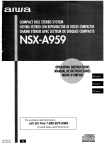
The numbers in the illustration below correspond to the following details.
@Surround speaker
@.Speaker system A
Right
Left
J
\
--,
@FM antenna
I
@Speaker system B
Left
Right
11111
REAR
@AM antenna
MD(?I I I
,-,3=
-=:
,
--,
to an AC outlet +=
L
-— . . . .
VIDEbIN L AUDIOINRI
to VIDEO IN
(Video 2)
Video 2 or
LD/MD nlaver
~:mwde
‘raeJJ
‘~
to&OOUTP”T
* When connecting a monaural wdeor use a
stereo-mono connecting cord (not supplied).
Turntable
to OUTPUT
--
3
ENGLISH
‘
__
)-*
,OVIDEO-N
CONNECTING
SPEAKERS @
Front smeakers
Speaker terminals
Connect front speakers (system A and/or B), a center speaker
and surround speakers to the corresponding speaker terminals
on the unit:
- the front speaker cords to the FRONT SPEAKERS terminals
- the center speaker cord to the CENTER SPEAKER terminals
- the surround speaker cords to the SURROUND SPEAKERS
terminals.
Lift up the terminal flap,
insert the speaker cord lead
into the terminal slot, then
close the flap. Check that the
cord is connected securely.
For more powerful bass, connect a sub woofer with a built-in
amplifier to the SUPER WOOFER d jack.
Center speaker
Speaker impedance
● Front
and center speakers
The SPEAKER IMPEDANCE SELECTOR on the rear should be
set to the position that matches the impedance value of the front
and center speakers.
When using 4 ohm speakers, set the selector to 4Q. When using
8 ohm speakers, set the selector to 8Q. Please unplug the AC
cord before setting the selector.
● Surround
speakers and super woofer
The SPEAKER IMPEDANCE SELECTOR has no effect on the
SURROUND SPEAKERS terminals and the SUPER WOOFER
~ jack. For the surround speakers and sub woofer, use speakers
of 8 ohms or more.
Connecting + to +, -to - terminals
To get the proper sound effect, the speaker terminals on the unit
and the speaker should be connected with proper polarity; the +
terminal on the unit should be connected to the + terminal on
the speaker (and – to –).
—
SPEAKER
IMPEDANCE
SELECTOR
m
●
●
●
L
9\!,;
Be sure to connect the speaker cords correctly as shown in
the illustration on the right column. Improper connections can
cause shorl circuits in the SPEAKER(S) terminals.
Do not leave objects generating magnetism near the speakers.
When using a sub woofer, select the speaker system A (see
page 6). Otherwise no sound can be heard from it.
Sub woofer
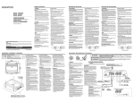
POSITIONING
THE SPEAKERS
Position the speakers to make the most of the Dolby Pro Logic
or DSP effect (see “DOLBY PRO LOGIC).
Surround speakers
@ Front speakers
@ Center speaker
Position in the center of the two front speakers. In addition,
position on or below the TV set, if connecting a TV set to the
unit.
@ Surround speakers
Place the surround speakers directly to the side of or slightly
behind the listening area. Align them horizontally, about 1
meter (3.2 feet) above ear height.
m
●
●
I
Sound is heard from the surround speakers when the DSP is
set to on.
Sound is heard from the center speaker mainly when the Dolby
Pro Logic is set to on. Note that when you select the PHANTOM
mode of the Dolby Pro Logic, the center speaker is muted.
(For details, see “DOLBY PRO LOGIC”).
5
..
/-----
I
1I ‘- —..—.———..—-—.—-—
—.—.—
.) L..___’_”___,,.
)
——.——
ENGLISH
4
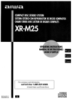
CONNECTING THE SUPPLIED ANTENNAS @
ABOUT THE REMOTE CONTROL
Connect the FM antenna to the FM 75 Q terminals and the AM
antenna to the AM LOOP terminals.
Inserting batteries
Detach the battery cover on the rear of the remote control and
insert two R6 (size AA) batteries.
FM antenna
antenna
R6(AA)
When to replace the batteries
The maximum operational distance between the remote control
and the sensor on the unit should be approximately 5 meters
(16 feet). When this distance decreases, replace the batteries
with new ones.
To stand the AM loop antenna on a surface
Fix the claw to the slot as shown in the illustration.
Using the remote control
The instructions in this manual refer mainly to the buttons on the
main unit. Buttons on the remote control with the same names
as those on the main unit can be used as well.
m
●
●
To position the antennas
FM feeder antenna:
Extend this antenna horizontally in a T shape and fix its ends to
the wall.
AM loop antenna:
Position for the best reception.
m
●
●
●
Do not bring the FM antenna near metal objects or curtain rails.
Do not bring the AM antenna near other external equipment,
the unit itself, the AC power cord or speaker cords, as noise
will be picked up.
Do not unwind the AM loop antenna wire.
CONNECTING
AN OUTDOOR ANTENNA
For better FM reception, use of an outdoor antenna is
recommended. Connect the outdoor antenna to the FM 75 Q
terminals.
If the unit is not going to be used for an extended period of
time, remove the batteries to prevent possible electrolyte
leakage.
The remote control may not operate correctly when:
- The line of sight between the remote control and the remote
sensor in the display window is exposed to intense light, such
as direct sunlight.
- Other remote controls are used nearby (those of television,
etc. )
Remote control operation
This remote control system allows you to operate other external
equipment besides the AIWA receiver. For details of the remote
control operation for other external equipment, see “REMOTE
CONTROL” on page 14.
Hereupon, it is explained how to operate the Aiwa receiver.
AlWA
RECEIVER
RECEIVER
KEY
MUTE
POWER
TUNER
PRESET
FUNCTION
VOLUME
1 Press the AIWA RECEIVER button to set the
remote control to the Aiwa receiver mode.
2 Press one of the buttons indicated above.
5
ENGLISH
FUNCTION button
Each time this button is pressed, the sound source changes
FM (or AM)’) ~V3~V2~Vl~CD~AUX~
PHONO
cyclically.
al:Either band, which you have tuned in fOrthe laSttime, ComesOn.
TUNER PRESET buttons
Tune in the station which has been preset on the receiver.
To go to a higher preset number, press the UPM
button. To
go to a lower preset number, press the DOWN H
button.
BEFORE OPERATION
TAPE MONITOR
POWER [ FUNCTION buttons
VOLUME
mH
It is not necessary to press the AIWA RECEIVER button each
time you operate the Aiwa receiver unless another mode has
already been set. (See “REMOTE CONTROL” on page 14.)
If the receiver cannot be operated with the remote
control
Follow the steps below with the remote control.
PHONES
FRONi SPEAKERS A, B
To turn the unit on
1 Turn the VOLUME control toward MIN.
Otherwise, the speakers may be damaged.
1 Press the AIWA RECEIVER button.
2 Press and hold the SET UP button for about 2.5
seconds.
The indicator on the top of the remote control blinks twice
while pressing the button.
3 Press the DIGIT buttons in the order of “4,” “O”
and “6.”
2 Press one of the FUNCTION buttons (TUNER,
PHONO, AUX/TV, CD, VIDEO 1, VIDEO 2 or
VIDEO 3) or the TAPE MONITOR button.
When pressing the TUNER button, the previously tuned
station is received (Direct Play Function).
The POWER button is also available.
Operation is possible after four seconds.
To select the front speaker system
To use speaker system A: Set the FRONT SPEAKERS A button
to sON.
To use speaker system B: Set the FRONT SPEAKERS B button
to sON.
To use both speaker systems : Set both the buttons to ~ ON.
Set the button(s) to 10FF to turn off the speaker system(s).
m
As the front speaker systems A and B are connected in series:
- The sound will be slightly decreased when using both speaker
systems
- No sound can be heard if the FRONT SPEAKERS A and B
buttons are set to ~ ON when only one speaker system is
connected
To change a displayed nalme for the AUX/TV button and
VIDEO 2 button
When the AUX/TV button is pressed, AUX is displayed initially.
It can be changed to TV.
With the power on, press the POWER button while pressing the
AUX/TV button,
The displayed name for VIDEO 2 button can be changed to
VIDEO 2, LD or MD; with the power on, press the POWER button
while pressing the VIDEO 2 button.
Using the headphones
Connect headphones to the PHONES jack with a standard stereo
plug (06.3 mm, 1/4 inch). Be sure to set the FRONT SPEAKERS
A and B buttons to 10FF. Otherwise sound is output from the
speakers.
m
When using the headphones, set the Dolby Pro Logic and DSP
system to off.
To turn the unit off
Press the POWER button.
ENGLISH
6
❑
CUSTOM AUDIO ADJUSTMENT
MUTl~G V?LUME
BALANCE
T-BASS
SUPER T-BASS SYSTEM
The T-BASS system enhances the realism of low-frequency
sound.
Press the T-BASS button.
Each time it is pressed, the level changes. Select one of the
three levels, or the off position to suit your preference.
Liibdk+mm+= 111111
BBE
J
(cancel)
VOLUME CONTROL
Turn the VOLUME control on the unit, or press the VOLUME
buttons on the remote control.
To adjust the Iefth’ight balance
Turn the BALANCE control.
To mute the sound temporarily
Press the MUTING button.
“MUTE ON” appears on the display for four seconds. While
muting the sound, the selected FUNCTION button flashes. Press
the MUTING button again to restore the sound.
BBE SYSTEM
The BBE system enhances the clarity of high-frequency sound.
Press the BBE button.
Each time it is pressed, the level changes. Select one of the
three levels, or the off position to suit your preference.
m
The BBE system is automatically canceled when Dolby Pro Logic
is turned on.
7
ENGLISH
m
Low-frequency sound may be distorted when the T-BASS system
is used for a disc or tape in which low-frequency sound is
originally emphasized. In this case, cancel the T-BASS system.
SOUND ADJUSTMENT DURING
RECORDING
The output volume and tone (except BBE) of the speakers or
headphones may be freely varied without affecting the level of
the recording.
Recording with the BBE
The desired source can be recorded with the BBE function to
enhance the clarity of high-frequency sound. When playing back
a tape recorded with BBE, it is recommended that BBE be set to
off.
ELECTRONIC GRAPHIC
EQUALIZER
DSP SURROUND
MANUAL
DSP SELECT
II
GEQ
DSP
DOWNY
uPA
G;Q
MANUAL SELECT
This unit provides the following five different equalization modes.
ROCK: Powerful sound emphasizing treble and bass
POP: More presence in the vocals and midrange
JAZZ: Accented lower frequencies for jazz-type music
CLASSIC: Enriched sound with heavy bass and fine treble
BGM: Calm tone with suppressed bass and treble
Press one of the GEQ (Graphic Equalizer) buttons.
The selected mode name appears on the display for two seconds,
and the selected mode on the right side of the display is enclosed
with parentheses,
The DSP (Digital Signal Processor) surround circuits can recreate
the effect of sounds reflected from walls or ceilings, to obtain
the sound presence of real environments. There are four modes
with matching graphic equalization modes. Equalization modes
are selected automatically and can also be selected or turned
off to suit your preference.
Press one of the DSP buttons (DANCE, LIVE, HALL
or ARENA).
The selected mode name appears on the display,- for two seconds.
.—,
and the selected DSP and matching GEQ modes on the display
are enclosed with parentheses.
m
~—Selec\ed
To cancel the selected mode
Press the selected button again. “GEQ oFF appears on the
display.
To select with the remote control
Press the GEQ button repeatedly until the desired equalization
mode is displayed.
DSP mode Matching GEQ mode
When the music source is monaural
Select LIVE to obtain a simulated stereo effect. When DANCE
or HALL is selected, no sound will be heard from the surround
speakers.
To cancel the selected mode
Press the selected button again. “DSP oFF appears on the
display. Even if canceling the selected DSP mode, the matching
or selected GEQ mode still remains. While the DSP surround
system is off, no sound is heard from the surround speakers.
To select with the remote control
Press the DSP button repeatedly until the desired DSP mode is
displayed.
To adjust the volume of the surround speakers
Press the MANUAL SELECT button once. “SUR” is displayed
for four seconds. Press the UPA or DOWNV button while “SUR”
is displayed.
Note that the Dolby Prv LvgiG surround apeakere level is als.v
changed (see page 13).
m
The DSP system is automatically canceled when the DOLBY
PRO LOGIC is turned on.
ENGLISH
8
RECORDING AN AUDIO SOURCE
SELECTION OF AUDIO/VIDEO
SOURCE
1
1
TAPE MONITOR
1 Select the program source.
1 Select the program source to be recorded.
Press one of the FUNCTION buttons orthe TAPE MONITOR
button.
Press one of the FUNCTION buttons.
2 Set the tape deck or MD recorder to the recording
mode,
3 Start the selected program source.
Radio
I TUNER
Record
I PHONO
I Television,
\ AUXiTVaJ
I
I Com~act disc
I CD
I
I Video (VCR or LD)
I VIDEO 1. VIDEO 2“, VIDEO 3
I
riii-
I VIDEO 2’)
I
etc.
+ For selecting AUX/TV, or VIDEO 2/LD/MD, see “TO change
a displayed name for the AUX/TV button and VIDEO 2
button” of “BEFORE OPERATION” (see page 6).
When using a turntable with a built-in equalizer amplifier, set the
switch of the equalizer amplifier to off. See the instructions of
the turntable for further information.
2 Start the selected program source.
3 Adjust the sound.
About the video source to the monitor or TV
Selected ~lDEO source
VI: VIDEO 1, V2: VIDEO 2, V3: VIDEO 3
The selected video source is indicated on the display and the
video signal through the MONITOR VIDEO OUT jack is output
on the TV.
9
ENGLISH
To monitor recorded sound during recording (when the
connected tape deck is a three-head system)
Press the TAPE MONITOR button. “TAPE ON” appears on the
display for four seconds, and then the source name selected in
step 1 comes back on. To cancel the tape monitor, press it again
so that “TAPE oFF appears.
Any sound control except the BBE system has no effect on
recording (see page 7).
DIRECT TUNING
MANUAL TUNING
MONO
TUNER
1,2
3
DOWNY, UPA
POWER 1
II
When you know the frequency of the desired station, you can
tune in directly to the station.
1 Press the TUNER button to select a band,
1 Press the TUNER button repeatedly to select the
desired band.
2 Press the TUNER button and hold it down until
“_” flashes on the display (Direct Tuning Modle).
~
When the TUNER button is pressed while the power is off,
the power is turned on directly.
2 Press the UPA
station.
or DOWNY
button to select a
Each time the button is pressed, the frequency changes.
When a station is received, “TUNE” is displayed for two
seconds. During FM stereo reception, [[101)) is displayed.
3 Press the appropriate numbered buttons to tulne
in to the desired station.
Example:
To tune into 106.50 MHz, press 1, 0, 6, 5 and O buttons.
To tune into 95.2 MHz, press 9, 5, 2 and Q buttons.
To cancel the Direct tuning mode
Press the UPA or DOWNT button.
To search for a station quickly (Auto Search)
Keep the UPA or DOWN~ button pressed until the tuner starts
searching for a station. After tuning in to a station, the search
stops.
To stop the Auto Search manually, press the UPA or DOWNV
button.
9 The Auto Search may not stop at stations with very weak
signals.
m
●
●
●
When entering a frequency out of tuning range, the vallue
flashes for two seconds and then goes off. Check the frequency
and repeat step 3 correctly.
When entering a frequency not covered by the tuning interval,
the value is automatically rounded up or down to the closest
one covered by it.
The DIGIT buttons on the remote control can not be used when
tuning in to the desired station.
When an FM stereo broadcast contains noise
Press the MONO TUNER button on the remote control so that
“MONO appears on the display.
Noise is reduced, although reception is monaural.
To restore stereo reception, press the button so that “MONO
disappears.
To change the AM tuning interval
The default setting of the AM tuning interval is 10 kHz/step. If
you use this unit in an area where the frequency allocation system
is 9 kHz/step, change the tuning interval.
Hold down the TUNER button and press the POWER button
immediately. Note that the unit is set to the Direct Tuning mode
if the TUNER button is pressed and held down for about two
seconds.
To reset the interval, repeat this procedure.
ENGLISH 10
PRESET NUMBER TUNING
PRESETTING STATIONS
1 Press the TUNER button to select a band.
E=ii
u
000
000
000
an
0:;0
00
0
00
ll_@-
Qi@’Ql@
——-—
I
UPFEI
DOWN
The unit can store a total of 32 preset stations. When a station is
stored, a preset number is assigned to the station. Use the preset
number to tune in to a preset station directly.
1 Press the TUNER button to select the band, and
press the UPA or DOWN7 button to select a
station. Direct tuning is also available.
2 Press the SET button to store the station.
A station is assigned a preset number, beginning from 1 in
consecutive order for each band.
Frequency
Preset “number
3 Repeat steps 1 and 2.
No ‘more stati&s will be stored if a total of 32 stations have
already been stored for all the bands.
m
When the AM tuning interval is changed, all preset stations are
cleared. The preset stations have to be set again.
11
ENGLISH
2 Press the numbered
number.
buttons to select a preset
Example:
To select preset number 25, press 2 and 5.
To select preset number 7, press O and 7.
To clear a preset station
Select the preset number of the station to be cleared. Then, press
the SET button, and press the SET button again within four
seconds.
The preset numbers of all other stations in the band with higher
numbers are decreased by one.
When using the remote control
Press UPM
or DOWNK
button to select a preset number.
m
The DIGIT buttons on the remote control can not be used when
selecting a preset number.
TO SELECT A DOLBY PRO LOGIC MODE
The Dolby Pro Logic feature and the center and surround
speakers (standard) assure full-scale home theater sound. When
playing back laser discs or video software that have been
recorded in Dolby Surround, astonishingly realistic sound
surrounds the listener to create a new level of audio/visual
entertainment.
Independent control of the four channels allows the listener to
enjoy the same type of sound reproduction experienced in movie
theaters. Voices are reproduced in the front and center sound
field, while ambient sounds like cars and crowds are reproduced
on all sides of the listener for an incredibly lifelike audio/video
experience. Please read the following carefully to “tune” the
system’s output to match the characteristics of your listening
space.
~.,
When selecting the DOLBY PRO LOGIC or 3CH LOGIC
mode, the indicator lights up, and the selected mode name
runs through on the display. Each time the button is pressed,
the mode changes as shown below.
r
DOLBY PRO LOGIC~
SELECTING DOLBY PRO LOGIC
3CH LOGIC
DOLBY PRO LOGIC oFF (cancel) 2
2 Press the DOLBY PRO LOGIC button again and
hold it down until the center speaker m;de to be
selected appears.
The optimal Dolby Pro Logic mode depends on the type and
placement of the speakers, It is recommended that the optional
Aiwa speakers should be used for all channels, for example, the
SX-R2000 for surround speakers, the SX-C2000 for a center
speaker and the SX-AV2000 for front speakers. Check your
current type and placement of the speakers and select the
recommended Dolby Pro Logic mode accordingly.
I
. ...
1 Press the DOLBY PRO LOGIC button repeatedly
to select the appropriate mode.
Check the following:
* Before using the DOLBY PRO LOGIC, adjust the proper
balance of the speaker sound levels (see page 13).
● Make sure the speakers are properly connected and positioned
(see pages 3 and 4).
● Make sure the TV set and video unit are properly
connected
(see page 3).
● Make
sure the laser disc and video tape, etc., support
❑ot-@
.
The recommended
.
When selecting the DOLBY PRO LOGIC mode in step 1:
“NORMAL’, “WIDE” and “PHANTOM” appear in turn.
When selecting the 3CH LOGIC mode in step 1:
“NORMAL’ and “WIDE” appear one after another.
mode
Center speaker
I
m
●
●
●
PHANTOM mode: Select this mode when the center speaker is
not connected. All center channel signals are redistributed to
the left and right channel speakers.
3CH LOGIC mode: Select this mode when the surround
speakers are not connected.
Depending on the sound source or listening condition, surround
effect may not be obtained even when the DOLBY PRO LOGIC
is on.
The full DOLBY PRO LOGIC effect cannot be obtained when
using the software without DDI=uw ~R~@ mark. In this case,
use the DSP surround system instead (see page 8).
The DOLBY PRO LOGIC system is automatically canceled
when the BBE or DSP system is turned on.
ENGLISH
12
❑
ADJUSTING
BALANCE
SPEAKER LEVEL
3
1
4 Press the MANUAL SELECT button again to stop
the noise signal.
If the surround speakers volume of the DSP is changed (see
page 8), the Dolby Pro Logic surround speakers level is also
changed.
1
2,4
BALANCE
2,4
The unit is equipped with a built-in test signal generator called a
noise sequencer for easy balance adjustment of all four channels.
The sequencer outputs a noise signal that “travels” from channel
to channel, enabling the simple adjustment of sound level to
achieve the same apparent loudness, at your listening position,
from each channel.
1 Select the Dolby Pro Logic mode according to
your current type and placement of the speakers.
(See page 12.)
2 Press the MANUAL SELECT button and hold it
down for about two seconds until “L TEST”
appears.
About the channels
The left and right speakers create the stereo effect.
The center speaker helps achieve precise sound positioning
over a broad sound field.
The rear-mounted surround speakers enhance the “depth” of
the sound field.
To change the delay time
The surround speakers reproduce sounds a split second after
the front speakers. The delay is initially set to 20 ms
(milliseconds).
To change this standard delay time, press the MANUAL SELECT
button twice or three times so that “TIME is displayed. Then,
press the UPA or DOWNT button. Each time one of the buttons
is pressed, the delay time changes as shown below.
15ms
~
20ms ++
30ms
To change the sound levels after adjusting the balance
with the noise sequencer
The sound levels of the center and surround speakers can be
adjusted during play of a laser disc or video software.
1 Press the MANUAL SELECT button once or twice to select
“CEN” or “SUR” (center or surround).
2 While the “CEN” or “SUR is displayed, press the UPA or
DOWNV button to adjust the volume.
A noise signal is sent to each channel in turn as follows:
DOLBY PRO LOGIC NORMAL or WIDE mode
r
L TEST (Left speaker)~TEST
u
CEN: (Center speaker)
SUR: (Surround speaker)~
DOLBY PRO LOGIC PHANTOM
L TEST-TEST
3 Adjust
the
mode
R-SUR
3CH LOGIC NORMAL
L TEST+TEST
R: (Right speaker
or WIDE mode
RaCEN
sound
level
of the
center
and
(or)
surround speakers.
While “CEN” or “SUR” is displayed, press the UPA or
DOWNY button to adjust the volume of the center or surround
speakers to match the level of the left and right speakers.
To adjust the balance between the left and right speakers,
use the BALANCE control while “L TEST” or “TEST R is
displayed.
13
ENGLISH
To confirm the stored ID code
You can check the stored ID code by counting the indicator
blinking.
OPERATING TV, CABLE TV, VCR
AND CD PLAYER
1 Press either the TV, CABLE, VCR or CD button.
For example, to check the stored code for CD player, press
CD.
You can control basic functions of a TV, CABLE TV, VCR and
CD player with this remote control.
2 Press and hold the SETUP Ibutton for about 2.5 seconds.
3 Press “9, “ “9” and “O”.
TO ENTER
THE ID CODE
EXTERNAL EQUIPMENT
OF
THE
4 Press “1,“ and count the indicator blinks.
For example, in the case that the stored ID is “157.”
The indicator blinks once.
5 Press “2,” and count the indicator blinks.
The indicator blinks five times.
Indicator
6 Press “3,” and count the indicator blinks.
The indicator blinks seven times.
DIGIT buttons
(o-9)
MODE SELECT
TO CONTROL TV, CAE3LETV, VCR AND CD
PLAYER
SET UP
CHANNEL
VOLUME
DIGIT buttons
(O-9) and ENTER
MODE SELECT
Before attempting to control them, be sure to enter the ID code
of the external equipment to the remote control as follows.
POWER
the code number of the external
1 Confirm
equipment.
See the ID code list in the “APPENDIX at the end of this
VCFVCD
ll:Pause, M: Stop,
M:Rewind,
>: Play,
~ :Fast forward
❑
manual.
2 Press either the TV, CABLE,
in the MODE SELECT area.
VCR
or CD button
1 Press any button in the MODE SELECT
CABLE, VCR or CD).
The remote control is ready to operate the selected mode
equipment.
3 Press and hold the SET UP button for about 2.5
seconds.
Confirm that the indicator blinks twice while pressing the SET
UP button.
area (TV,
2 Press one of the buttons
indicated
above.
to
For the use of the O-9 and the ENTER buttons, seethe instruction
manual supplied with the unit to be controlled.
For example, if your CD player is an AIWA unit, the required
ID code is 124 or 157. In this case, press the DIGIT buttons
in the order of”1 ,“”2 and “4 (or “1 ,“ “5” and 7“ ).
Other buttons indicated above have the same function which
you will find on the unit to be controlled.
4 Press three DIGIT buttons which correspond
the ID code of the external equipment.
After the third DIGIT button is pressed, the indicator blinks
twice indicating that the ID code is correct and is stored on
the remote control.
●
●
Reenter the ID CODE of the external equipment after replacing
the batteries of the remote control.
If there are plural ID codes for external equipment in the
“APPENDIX,” try each number listed until you can control the
external equipment.
ENGLISH
14
SETTING THE CLOCK
SETTING THE SLEEP TIMER
f~G
CLOCK
--+
0000
000
000
—2
1,3,5
1
00
Ja)oo=
00
3
.=,
2,4
The receiver can be automatically turned off at a specified time.
When the AC cord is connected for the first time, the clock on
the display flashes.
Set the time as follows while the power is off.
Use the remote control.
1 Press the AIWA RECEIVER button.
2 Press the SLEEP button.
1 Press the SET button.
The hour flashes.
2 Press the DOWNY
the hour.
or
UPA button to designate
3 Press the SET button to set the hour.
The hour stops flashing and the minute starts flashing.
4 Press the DOWNV
the minute.
3 Press the UPor DOWNfour seconds
to specify
the power is turned off.
the
button within
time until
Each time the button is pressed, the time changes between 5
and 240 minutes in 5-minute steps.
Specified time
or UPA button to designate
5 Press the SET button to set the minute.
The minute stops flashing on the display and the clock starts
from 00 second.
To correct the current time
Press the POWER button to turn the unit off. Press the SET
button and carry out steps 1 to 5 above.
To display the current time
Press the CLOCK button on the remote control. The clock is
displayed for 4 seconds.
To switch to the 24-hour standard
Press the POWER button while pressing the UPA or DOWNY
button while the current time is displayed.
Repeat the same procedure to restore the 12-hour standard.
If the clock display flashes while the power is off
This is caused by a power interruption. The current time needs
to be reset.
If power is interrupted for more than approximately 24 hours, all
settings stored in memory after purchase need to be reset.
15
ENGLISH
To check the time remaining until the power is turned off
Press the SLEEP button once. The remaining time is displayed
for four seconds.
To cancel the sleep timer
Press the SLEEP button twice so that “SLEEP
disappears.
on the display
CARE AND MAINTENANCE
Occasional care and maintenance of the unit is needed to
optimize the performance of your unit.
To clean the cabinet
Use a soft dry cloth.
If the surfaces are extremely dirty, use a soft cloth lightly
moistened with mild detergent solution. Do not use strong
solvents, such as alcohol, benzine or thinner as these could
damage the finish of the unit.
SPECIFICATIONS
FM tuner section
Tuning range
Usable sensitivity
(IHF)
Antenna terminals
87.5 Mt+z to 108 MHz
13.2 dBf
75 ohms (unbalanced)
AM tuner section
Tuning range
530 kHz to 1710 kHz (10 kHz step),
531 kHz to 1602 kHz (9 kHz step)
350 pVlm
Loop antenna
Usable sensitivity
Antenna
Amplifier section
Power output
Total harmonic
distortion
Inputs
outputs
[Stereo Mode]
Front
125 watts per channel, Min. RMS at 4
or 8 ohms, from 40 Hz to 20 kHz, with
no more than 0.8% Total Harmonic
Distortion
[Dolby Pro Logic Mode]
Front
120 waitts per channel, Min. RMS at 4
or 8 ohms (selectable), from 40 Hz to
20 kHz, with no more than 0.97. Total
Harmonic Distortion
Rear (Surround)
60 watts per channel, Min. RMS at 8
ohms, 1 kHz, with no more than 0.90/0
Total Harmonic Distortion
Center
120 watts, Min. RMS at 4 or 8 ohms
(selectable), 1 kHz, with no more than
0.9% Total Harmonic Distortion
0.07 % (105 W, 1 kHz, 8 ohms, Front)
AUDIO IN
f>HONO: 2.8 mV (50 kohms)
CD: 370 mV (50 kohms)
TAF’E MONITOR: 200 mV (25
kohms)
\/lDEO 1, VIDEO 2/LD/MD,
VIDEO 3, AUWTV 370 mV (50
kohms)
VIDE;O IN: 1 Vp-p (75 ohms)
AUDIO OUT (REC OUT): 230 mV (2
kohrns)
VIDEO OUT (MONITOR): 1 Vp-p (75
ohms)
SUPER WOOFER: 3.1 V
FRONT SPEAKERS IMP: 8Q/4Q
selectable (front speakers A and B):
With the SPEAKER IMPEDANCE
SELECTOR set to 4Q, accepts
speakers of 4 ohms.
With the SPEAKER IMPEDANCE
SELECTOR set to 8f2, accepts
speakers of 8 ohms or more.
SURRCWND SPEAKERS IMP: 8Q
(surround speakers): accepts
speakers of 8 ohms or more
ENGLISH
16
Muting
CENTER SPEAKER IMP: 8Q14f2
selectable
With the SPEAKER IMPEDANCE
SELECTOR set to 4Q, accepts
speaker of 4 ohms.
With the SPEAKER IMPEDANCE
SELECTOR set to 8Q, accepts
speaker of 8 ohms or more.
PHONES (stereo jack): accepts
headphones of 32 ohms or more
-20 dB
General
Power requirements
Power consumption
Dimensions
(W XHXD)
Weight
120 V AC, 60 Hz
210 W
360 x 153.5x 335 mm
(141/, x 6’/0 x 131/, in.)
10.3 kg (22 lb 11 OZ.)
Specifications and external appearance are subject to change
without notice.
BBEsYsTEM
The word “BBE and the “BBE symbol” are trademarks of BBE
Sound, Inc.
Under license from BBE sound, Inc.
DOLBY PRO LOGIC
Manufactured under license from Dolby Laboratories Licensing
Corporation.
“DOLBY” the double-D symbol OU and “PRO LOGIC” are
trademarks of Dolby Laboratories Licensing Corporation.
TROUBLESHOOTING
GUIDE
If the unit fails to perform as described
Instructions, check the following guide.
in these Operating
GENERAL
There is no sound.
● Is the AC cord connected properly?
● Is there an incorrect connection? (+
page 3)
● There may be a short circuit in the speaker terminals.
~ Disconnect the AC cord, then correct the speaker
connections.
● Was an incorrect function button pressed?
● Are the FRONT SPEAKERS
A and B buttons set correctly?
(- page 6)
Sound is emitted from one speaker only.
● Is the BALANCE control set appropriately?
● Is the other speaker disconnected?
Sound is heard at a very low volume.
c Has the MUTING button been pressed?
An erroneous display or a malfunction occurs.
+ Reset the unit as stated below.
TUNER SECTION
There is constant, wave-like static.
● Is the antenna connected properly? (+
page 5)
● Is the FM signal weak?
+ Connect an outdoor antenna.
The reception contains noise interference or the sound is
distorted.
● Is the system picking up external noise or multipath distortion?
- Change the orientation of the antenna.
+ Move the unit away from other electrical appliances.
To reset
If an unusual condition in the display window or malfunction
occurs, reset the unit as follows.
1 Press the POWER button to turn off the power.
2 Press the POWER button while pressing the SET button.
Everything stored in memory after purchase is canceled.
If the power cannot be turned off in step 1 because of a
malfunction, reset by disconnecting the AC cord and carry out
step 2.
17
ENGLISH
PARTS INDEX
Instructions about each part on the unit or remote control are
indicated on the pages listed below.
~a;~habetical
order)
AIWA RECEIVER
AUXITV
BALANCE
BBE
CD
CLOCK
DOLBY PRO LOGIC
DOWN T (M)
DSP
FRONT SPEAKERS A, B
FUNCTION
GEQ
Indicator
MANUAL SELECT (TEST)
MONO TUNER
MUTING, MUTE
PHONES
PHONO
POWER
SET
SET UP
SLEEP
SPEAKER IMPEDANCE
SELECTOR
TAPE MONITOR
T-BASS
TUNER, BAND DIRECT
TUNER PRESET
UP A (w)
VIDEO 1
VIDEO 2, LD/MD
VIDEO 3
VOLUME (V,
A)
Pages
5, 15
6, 9
7, 13
7
6, 9
15
12, 13
8,10,11,13,15
8
6
6, 9
8
14
8, 13
10
7
6
6, 9
6, 10, 15
11,15
14
15
4
6, 9
7
6,9,10,11
6
8,10,11,13,15
6, 9
6, 9
6, 9
7, 14
ENGLISH
18
PRECAUCIONES
Antes de utilizar la unidad, lea cuidadosa y completamente este
manual instrucciones. Guarde el manual de instrucciones para
futuras referencias. Todos Ios avisos y precauciones del manual
de instrucciones y de la unidad deberan seguirse estrictamente,
asi como Ias sugerencias de seguridad indicadas a continuation.
Instalacion
1 Agua y humedad — No utilice esta unidad cerca del agua,
como al Iado de una batlera, un Iavabo, una piscina, etc.
2 Calor — No utilice esta unidad cerca de fuentes termicas,
como salidas de calefaccion, estufas, ni demas aparatos que
generen calor.
Tampoco debera someterse a temperatures inferiors a 5°C
(41 “F) ni superiors a 35°C (95”F).
3 Superficie de montaje — Coloque la unidad sobre una
superficie plana y nivelada.
4 Ventilation
— La unidad debera colocarse donde tenga
espacio suficiente a su alrededor para asegurar su ventilation
adecuada. Deje un espacio Iibre de 10 cm en la parte posterior
y superior de la unidad, y de 5 cm a cada Iado.
- No la coloque sobre una cama, una alfombra, ni nada similar
que pueda bloquear Ias aberturas de ventilation.
- No la instale en una Iibrer(a, un armario, ni un bastidor
cerrado, donde la ventilation podr~a ser deficient.
5 Entrada de objetos y Iiquidos — Tenga cuidado de que en
interior de la unidad no entren objetos pequefios ni
el
I(quidos a traves de Ias aberturas de ventilation.
6 Carritos y estantes — Cuando
haya colocado o montado la unidad
sobre un estante o un carrito, debera
moverla con cuidado.
k
Las paradas repentinas, la fuerza
o Ias superficies
excesiva,
m A&a 3
desiguales podrfan causar el vuelco
o la ca(da de la combination de la unidad y el carrito.
7 Montaje en una pared o en el techo — La unidad no debera
montarse en una pared ni en el techo, a menos que se
especifique en el manual de instrucciones.
●
Eneruia electrica
1 Fuentes de alimentacion — Conecte esta unidad solamente
Anotacion del propletario
Para su conveniencia, anote el ntimero de modelo y el numero
de serie (Ios encontrara en el panel trasero de su aparato) en el
espacio suministrado mas abajo. Mencionelos cuando se ponga
en contacto con su concesionario Aiwa en caso de tener
dificultades.
I N.” de modelo
I AV-X220
1
ESPANOL
N.” de serie (N.Ode Iote)
I
I
a Ias fuentes de alimentaci6n especificadas en Ias
instruccionesde manejo, y como esta marcado en la unidad.
2 Polarization
— Como medida de seguridad, algunas
unidades disponen de enchufes de alimentacion de CA
polarizados que solamente podran insertarse de una forma
en el tomacorriente de la red. Si es diffcil o imposible insertar
el enchufe de alimentacion de CA en un tomacorriente de la
red, dele la vuelta e intentelo de nuevo. Si sigue sin poder
insertarse bien, Ilame a un tecnico de servicio cualificado
para que reemplace ei tomacorriente. para evitar anular la
funcion de seguridad del enchufe polarizado, no 10inserte a
la fuerza en un tomacorriente.
3 Cable de alimentacion de CA
- Para desconectar el cable de alimentacion, tire del enchufe
de CA. No tire del propio cable.
- No tome nunca el cable de alimentaci6n de CA con Ias
manes humedas, ya que esto podr~aresultar en incendios
o descargas electrical.
- No pise el cable de alimentacion ni 10 pine con objetos
colocados encima o contra 61,ya que podrian producirse
incendios o descargas electrical.
- Evite sobrecargar
Ios tomacorrientes
y Ios cables
prolongadores por encima de su capacidad, ya que esto
podr~a resultar en incendios o descargas electrical.
Cable prolongador — Para evitar descargas electrical, no
utilice el enchufe de alimentacion de CA polarizado con un
cable prolongador ni tomacorriente a menos que el enchufe
pueda insertarse completamente a fin de evitar que sus
cuchillas queden al descubierto.
— Cuando no vaya a utilizar la
5 Periodos sin utilization
unidad durante varies meses, desenchu(e el cable de
alimentacion de CA del tomacorriente de la red. Cuando el
cable de alimentacion
estas enchufado, circulara una
pequeha corriente
por la unidad, incluso aunque la
alimentacion este desconectada.
4
Antena exterior
PREPARATIVES ................................................................. 1
PREPARATIONS
CONEXIONES ..................................................................... 3
ANTES DE LA OPERACIONI .............................................. 6
SONIDO
1 Lineas electrical — Cuando conecte una antena exterior,
cerciorese de que este alejada de Ias Iineas electrical.
2 Puesta a tierra de la antena exterior — Cerciorese de aue
el sistema de antena este adecuadamente puesto a tie”rra
como medida de protecci6n
contra sobretensiones
inesperadas o la generaci6n de electrostatic.
El art(culo
810 del codigo National Electric Code, ANSUNFPA70
proporciona information sobre la puesta a tierra adecuada
del mastil, la estructura de soporte, y la acometida a la unidad
de descarga de la entena, asi como sobre el tamario de la
unidad de puesta a tierra, la conexion de Ios terminals de
puesta a tierra, y Ios requisites de puesta a tierra de Ios
propios terminals.
Puesta a tierra de [e antena de acuerdo con el codigo National Electric Code
AJUSTE DEL SONIDO A S1; GUSTO ............................... 7
ECUALIZADOR GRAFICO ELECTRONIC
..................... 8
SONIDO PERIMETRICO DEL PROCESADOR
DE SENAL DIGITAL ........................................................... 8
OPERAClONES
BASICAS
SELECCION DE UNA FUENITE DE AUDIO/VIDEO ..........9
GRABACION DE UNA FIJENTE DE AUDIO ..................... 9
ESCUCHA
DE LA RADIO
SINTONIA MANUAL ......................................................... 10
SINTONIA DIRECTA ......................................................... 10
MEMORIZATION DE EMISC)RAS ................................... 11
AcOMETIDA DE ANTENA
DOLBY PRO LOGIC
, UNIDAD DE DESCARGA DE ANTENA
(aECClOM 810.20 DEL MEC)
SELECCION DE DOLBY PRO LOGIC ............................ 12
AJUSTE DEL EQUILIBRIA IDEL NIVEL
ENTRE ALTAVOCES ........................................................ 13
CONTROLADOR
REMOT()
W(SECC’”N81””21DELN
CONDUCTORES DE PUESTA A TIERRA
ABRAZADERAS DE PUESTA ATIERRA
, ~
CODIGO
ELECTRICO
NACIONAL,
SISTEMA DE ELECTFIODOS DE PUESTA A
TIERRA DEL SERVICIO ELECTRICO
(ART. 250, PARTE H DEL NEC)
Mantenimiento
Dai70s que requieren reparation
Haga que la unidad sea revisada por un tecnico de servicio
cualificado si:
- se ha darlado el cable de alimentacion o el enchufe de CA.
- en el interior de la unidad han entrado objetos o Iiquidos.
- la unidad ha estado expuesta a la Iluvia o al agua.
- la unidad parece no funcionar normalmente.
- la unidad presenta un cambio notable en su rendimiento.
- la unidad ha caido, o se ha dafiado su caja.
NO INTENTE REPARAR USTED MISMO LA UNIDAD.
su unidad y accesorios
Receptor estereo AV-X220
H
TEMPORIZADOR
NEC
Limpie la unidad solamente como se recomienda en el manual
de instrucciones.
Compruebe
OPERACION DE UN TELEVISOR, SISTEMA DE
CABLEVISION, VIDEOGRABADORA, Y REPRODUCTOR
DE DISCOS COMPACTOS .,>..,.......................................... 14
Controlador remoto
PUESTA EN HORA DEL RELOJ ..................................... 15
PROGRAMACION DEL
TEMPORIZADOR CRONODIESCONECTADOR .............15
GENERALIDADES
CUIDADOS Y MANTENIMIENTO .................................... 16
ESPECIFICACIONES ....................................................... 16
GUIA PARA LA SOLUCION DE PROBLEMAS ............. 17
INDICE DE LAS PARTES ................................................. 18
APENDICE
CODIGOS DE IDENTIFICATION PARATELEVISION ... A-1
CODIGOS DE lDENTIFICACION PARA
CABLEVISION ................................................................ A-2
CODIGOS DE IDENTIFICATION PARA
VIDEOGRABADORAS ................................................... A-3
CODIGOS DE IDENTIFICATION PARA
REPRODUCTORES DE DISCOS COMPACTOS .......... A-4
u
Antena de FM
Antena de AM
Manual de instrucciones, etc.
*
ESPANOL
2
CONEXIONES
CONEXION
DE EQUIPOS
Las clavijas de Ios cables conectores y Ias tomas estan
codificadas en color de la forma siguiente:
Clavijas y tomas rojas: Para el canal derecho de sehales de
audio
Clavijas y tomas blancas: Para el canal izquierdo de sefiales
de audio
Clavijas y tomas amarillas: Para sehales de video
Antes de conectar el cable de aiimentacion de CA
La tension nominal de su unidad indicada en el panel posterior
de su unidad es de 120 V CA, Compruebe si esta tension
coincide con la de la red local.
IMPORTANTE
Conecte primero Ios altavoces, Ias antenas, y todos Ios demas
equipos externos. Despu6s conecte el cable de alimentacion
de CA.
m
Inserte Ias clavijas de Ios cables conectores firmemente en Ias
tomas. Las conexiones flojas podrian producir zumbidos u otras
interferencias de ruido.
Los numeros de esta ilustracion corresponded a Ios detalles siguientes.
~ Altavoces perimetricos
@ Sistema dealtavoces A
1
11111
-
13?&35&3@i5
I I
Parte frontal
722%9
VIDE IN L AUUiOIN
R
a VIDEO OUT J
LA--if’
;
I
VIDEO2! D
0
a VIDEO OUT
(Videoarabadora
201
—
w
a
J
J
=,
tifiuvlu
VIDEO
1
OUT
7.
-
)N
S-,
Uu
1/
a AUDIO IN
(Videograbadora
.
,:,
EARTH
h
,,-
J 11111I I II
2/
I
I
a AUDIO OUT
~~>
;!, sl~~AL
iij$
“‘:;
.,,.
ml‘“‘“:q
d .(i;,
.
T
reproductor de minidiscos)
.,
(
a OUTPUT
I -..-[
I
Televisor
ml
* Para
- =.-... ....___monoaur’al utilim? (m cable
. . crmectar
------ . una
. ..-. virk=xmrahadora
-—-..
conector estereo-monoaural (no suministrado)’. - ““””-- ‘“’”
Deck de casetes
3
ESPAiiOL
Izquierdo
/yma:wfq
J
a VIDEO IN
(video 2)
Derecho
Giradiscos
~
J
\I
I
CONEXION
DE LOS ALTAVOCES @)
Altavoces delanteros
Terminates para altavoces
Conecte Ios altavoces delanteros (sistema A y/o B), un altavoz
central, y altavoces perimetricos a 10sterminals para altavoces
correspondientes de la unidad.
- Ios cable de Ios altavoces delanteros a Ios terminals FRONT
SPEAKERS
- el cable del altavoz central a CENTER SPEAKER
- Ios cables de Ios altavoces perimetricos a Ios terminals
SURROUND SPEAKERS
Para obtener un sonido mas potente, conecte un altavoz de
subgraves con altavoz incorporado a la toma SUPER WOOFER
~.
Impedancia de Ios altavoces
. Altavoces delanteros y central
El selector SPEAKER IMPEDANCE SELECTOR del panel
posterior debera ponerse en la position correspondiente al valor
de impedancia de Ios altavoces delanteros y central.
Cuando utilice altavoces de 4 ohmios, ponga el selector en 4Q.
Cuando utilice altavoces de 8 ohmios, ponga el selector en 8Q.
Antes de ajustar el selector, desenchufe el cable de alimentacion
de CA.
● Altavoces
perimetricos y altavoz de subgraves
EL selector SPEAKER IMPEDANCE SELECTOR no afecta a
Ios terminates SURROUND SPEAKERS ni a la toma SUPER
WOOFER 4. Para Ios altavoces perimetricos y et altavoz de
subgraves, utilice altavoces de 8 ohmios o mas.
Levante la Iengueta del
terminal, inserte el
conductor del cable del
altavoz en el orificio del
terminal, y despues cierre
la Iengueta. Compruebe si
el conductor ha quedado
conectado con seguridad.
Altavoz central
SPEAKER—#————=
IMPEDANCE
SELECTOR
m
I
Conexion de Ios terminals+
a +, y - a Para obtener el efecto actistico apropiado, Ios terminals de la
unidad y de Ios altavoces deberan conectarse con la polaridad
apropiada: Ios terminals + de la unidad deberan conectarse a
Ios terminals + de Ios altavoces (y - a -).
m
Cerciorese de conectar correctamente
Ios cables de Ios
altavoces como se muestra en la columns de la derecha. La
conexion inapropiada podria causar cortocircuitos en Ios
terminals SPEAKER(S).
● No coloque
objetos que generen magnetism
cerca de Ios
altavoces.
● Cuando utilice un altavoz de subgraves,
seleccione el sistema
ce altavoces A (consulte la pagina 6). De 10contrario, no saldrfa
sonido a traves de 61.
II
&
Q
●
o
‘~
,Altavoz de subgraves
Altavoces perimetricos
UBICACION DE LOS ALTAVOCES
Coloque Ios altavoces de forma que obtenga el maximo efecto
del sistema Dolby Pro Logic o del procesador de sehal digital
(DSP) (consulte “DOLBY PRO LOGIC).
@ Altavoces delanteros
@ Altavoz central
Coloquelo en el centro de Ios dos altavoces delanteros.
Ademas, si ha conectado un televisor a la unidad, coloque el
altavoz sobre o debajo del mismo.
@l Altavoces perimetricos
Coloquelos directamente a Ios Iados del area de escucha o
Iigeramente detras de ells. Alineelos horizontalmente,
a
aproximadamente 1 metro sobre la altura de Ios ofdos.
13ZZ3
Cuando active el procesador de serial digital, oira sonido a
traves de Ios altavoces perimetricos.
● Cuando
active el sistema Dolby Pro Logic, el sonido se oira
principalmente a traves del altavoz central. tenga en cuenta
que cuando haya seleccionado el modo PHANTOM de Dolby
Pro Logic, el altavoz central se silenciara. (Con respecto a Ios
detalles, consulte “DOLBY PRO LOGIC.)
@
I
●
~
L.——._.~
ESPANOL
4
CONEXION DE LAS ANTENAS
SUMINISTRADAS @
SOBRE EL CONTROLADOR
REMOTO
Conecte la antena de FM a Ios terminals
de AM a Ios terminals AM LOOP.
Quite la tapa del compartimiento de Ias pilas de la parte posterior
dei controlador remoto e inserte dos pilas R6 (AA).
Insertion de Ias pilas
FM 75 Q y la antena
Antena de FM
&
T’
de cuadro
D
R6(AA)
Cuando reemplazar Ias pilas
Para colocar
la antena
de cuadro
de AM sobre una
La distancia maxima de operation entre el controlador remoto y
el sensor de la unidad debera ser de aproximadamente 5 metros.
Cuando esta distancia se reduzca, reemplace Ias pilas por otras
nuevas.
superficie
Fije la uha en la ranura como se muestra en la i[ustracion.
Utilization del controlador remoto
Las instrucciones de este manual se refieren principalmente a
[OSbotones de la unidad principal. Los botones del controlador
remoto con Ios mismos nombres que Ios de la unidad principal
tambien podran utilizarse.
●
●
Ubicacion de Ias antenas
Antena en T de FM:
Extienda horizontalmente esta antena en forma de T y fije sus
extremes a una pared.
Antena de cuadro de AM:
Coloquela con la orientation optima.
No acerque la antena de FM a objetos metalicos ni a rieles de
cortinas.
● No acerque la antena de AM a otros equipos externos, la propia
unidad, el cable de alimentacion de CA, ni Ios cables de Ios
aitavoces, porque podria captar ruido.
QNo desbobine la antena de cuadro de AM.
●
CONEXION
DE UNA ANTENA EXTERIOR
Para mejorar la recepcion de FM, se recomienda utilizar una
antena exterior. Conecte la antena exterior a Ios terminals FM
75 Q.
Cuando no vaya a utilizar la unidad durante mucho tiempo,
extraigale Ias pilas para evitar la posible fuga de su eiectrolito.
Es posible que el controlador remoto no funcione correctamente
cuando:
- La Iinea de vision entre el controlador remoto y el sensor de
control remoto del interior del visualizador este expuesta a
una Iuz intensa como, por ejemplo, la Iuz solar directs.
- Esten utilizandose cerca otros controladores remotos (de un
televisor, etc.).
Operation del controlador remoto
Este sistema de cotrol remoto Ie permitira gobernar equipos
externos ademas del receptor Aiwa. Con respecto a Ios detailes
sobre la operation de control remoto de gobernar equipos
externos, consulte “CONTROLADOR REMOTO” de la pagina
14. A continuation se explica como controlar el receptor Aiwa.
AIWA
RECEIVER
RECEIVER
KEY
MUTE
POWER
TUNER
PRESET
‘uNcT’ONvvOLuM
1 Presione el boton AIWA RECEIVER para poner
el controlador remoto en el modo de receptor
Aiwa.
2 Presione uno de Ios botones indicados
5
ESPANOL
arriba.
Boton FUNCTION
Cada vez que presione este boton, la fuente de sonido cambiara
ciclicamente en la forma siguiente: FM (o AM)’) ~ V3 ~ V2 ~
VI + CD + AUX + PHONO.
@:Aparecerala banciaque haya sintonizado por Ultima W?Z.
ANTES DE LA OPERACION
TAPE MONITOR
POWER I Botones FUNCTION
VOLUME
Botones TUNER PRESET
Sintonizan Ias emisoras memorizadas en el receptor.
Para pasar a un numero de memorization mas alto, presione el
boton UP-.
Para pasar a un numero de memorization mas bajo, presione
el boton DOWN H,
PHONES
No es necesario que presione el boton AIWA RECEIVER cada
vez que controle su receptor Aiwa a menos que haya ajustado
otro modo. (Consulte “UTILIZATION DEL CONTROLADOR
REMOTO” de la pagina 14.)
Para conectar
FRONT SPEAKERS A, B
la alimentalcion
1 Gire el control VOLUME
de la unidad
hacia MIN.
De 10contrario, Ios altavoces podrian daiiarse.
Si el receptor
no puede
controlador remoto
gobernarse
con
el
Realice Ios pasos siguientes con el controlador remoto.
1 Presione el boton AIWA RECEIVER.
2 Mantenga presionado
unos 2,5 segundos,
el boton SET UP durante
El indicador de la parte superior del controlador
parpadeara dos veces mientras presione el boton.
remoto
3 Presione Ios botones DIGIT en el orden de “4”,
“O”, y “6”.
2 Presione uno de km botones FUNCTION (TUNER,
PHONO, AUX/TV, CD, VIDEO 1, VIDEO 20 VIDEO
3) o el boton TAPE MONITOR.
Cuando presione el boton TUNER, se recibira la emisora
previamente sintonizada (funsion de reproduction directs).
Tambien podra utilizarse el boton POWER. La operation
sera posible despues de cuatro segundos.
Seleccion
del sistema de altavoces
delanteros
Para utilizar el sistema de altavoces A: Ponga el boton FRONT
SPEAKERS A en sON.
Para utilizar el sistema de altavoces B: Ponga el bot6n FRONT
SPEAKERS Ben -ON.
Para utilizar ambos sistemas de altavoces:
Ponga ambos
botones en wON.
Para desconectar uno de Ios sistemas (o ambos sistemas) de
altavoces, ponga el boton (o Ios botones) en J.OFF.
m
Como Ios sistemas de altavoces delanteros A y B estan
conectados en serie:
- El sonido se reducira Iigeralmente cuando utilice ambos
sistemas de altavoces.
- No se oira sonido si Ios botones FRONT SPEAKERS A y B
estan en ~ ON cuando solamente haya conectado un sistema
de altavoces.
Para cambiar el nombre visualizado para el boton ALDU
TV y el boton VIDEO 2
Cuando presione el boton AUWTV, inicialmente se visualizar~
AUX, Usted podra cambiar la indication a TV.
Para conectar la alimentacion, presione el boton POWER
manteniendo pulsado el boton AUX/TV,
El nombre visualizado para el bcion VIDEO 2 podra cambiarse
a VIDEO 2, LD, o MD. Con la alirnentacion conectada, presione
el boton POWER manteniendo pulsado el bot6n VIDEO 2.
Utilization
de auriculares
Conecte Ios auriculares con clavija estereo estandar (6,3 mm
de dia.) en la toma PHONES. Cerciorese de que IOSbotones
FRONT SPEAKERS A y B no esten en 10FF. De 10contrario,
el sonido saldrla a traves de Ios altavoces,
Cuando utilice auriculares, desactive el sistema Dolby Pro Logic
y el procesador de sefial digital.
Para desconectar la alirnentacion
Presione el boton POWER.
de la unidad
ESPANOL
6
❑
SISTEMA
AJUSTE DEL SONIDO A SU
GUSTO
MUTl~G V?LUME
BALANCE
CONTROL
T-BASS
BBE
DEL VOLUMEN
Gire el control VOLUME de la unidad o presione Ios botones
VOLUME del controlador remoto.
Para ajustar el equilibria entre Ios canales izquierdo y
derecho
Gire el control BALANCE.
Para silenciar temporalmente el sonido
Presione el boton MUTING.
En el visualizador
aparecera “MUTE ON” durante cuatro
segundos.
Mientras el sonido este silenciado,
el boton
FUNCTION seleccionado parpadeara.
Para restablecer el
sonido, vuelva a presionar el bot6n MUTING.
SISTEMA BBE
El sistema BBE realza la claridad del sonido de alta frecuencia.
Presione el boton BBE.
Cada vez que presione el boton, el nivel cambiara. Seleccione
a su gusto uno de Ios tres niveles o la posici6n de cancelacion.
L
iba+i4LImw=4m
111111
1
, (cancelacih)
El sistema BBE se cancelara automaticamente
sistema DOLBY PRO LOGIC.
7
ESPANOL
cuando active el
SUPER T-BASS
El sistema T-BASS realza el realismo del sonido de baja
frecuencia.
Presione el boton T-BASS.
Cada vez que presione el boton, el nivel cambiara.
Seleccione a su gusto uno de Ios tres niveles o la posici6n de
cancel acion
111111
bd&L.mEw4iBm
(cancelacion)
El sonido de baja frecuencia puede distorsionarse cuando utilice
el sistema T-BASS con un disco o un casete CUYOsonido de
baja frecuencia haya sido acentuado originalmente.
En este
case, cancele el sistema T-BASS.
AJUSTE DEL SONIDO DURANTE LA
GRABACION
El volumen y el tono de salida (excepto BBE) de Ios altavoces o
de Ios auriculares podran variarse Iibremente sin que se vea
afectado el nivel de grabacion.
Grabacion con el sistema BBE
Usted podra grabar la fuente deseada con la funcion BBE para
reforzar la claridad del sonido de alta frecuencia. Para reproducer
una cinta grabada con el sistema BBE, se recomienda cancelar
tal sistema.
ECUALIZADOR
ELECTRONIC
SONIDO PERIIVIETRICODEL
PROCESADORDE SENALDIGITAL
GRAFICO
MANUAL
DSIP ;ELECT
GEQ
GEQ
DSP
DOWNY
uPA
UPW
DOWN
I
MANUAL SELECT
Esta unidad dispone
siguientes.
de Ios cinco modos de ecualizacion
ROCK: Acentua el sonido de graves y agudos.
POP: Ofrece mas presencia a Ias votes y a la gama media.
JAZZ: Acenttia Ias frecuencias bajas para mtisica de tipo jazz.
CLASSIC: Ofrece sonido rico con graves profundos y agudos
delicados.
BGM: Ofrece tono calmado con graves y agudos suprimidos.
Presione uno de Ios botones GEQ (ecualizador grafico).
El nombre dei modo seleccionado aparecera en el visualizador
durante dos segundos, y en se encerrara entre parenthesis en la
parte derecha del visualizador,
Los circuitos de sonido perim4trico del procesador de seiial
digital (DSP) pueden recrear el efecto de sonidos reflejados en
paredes o techos, para ofrecer la presencia de sonido de
ambientes reales. Existen cuatro modos correspondientes a
Ios modos de ecualizacih grafica. Los modos de ecualizaci6n
se seleccionaran automaticarnente, y tambien podra seleccionar
o desactivarlos a su gusto.
Presione uno de Ios botcmes DSP (procesador
sehal digital) (DANCE, LIVE, HALL o ARENA)
de
El nombre del modo seleccionado aparecera en el visualizador
durante dos segundos, y tambi6n se visualizaran Ios modos del
DSP y del GEQ adecuados.
Modo seleccionado z
~—
Para cancelar el modo seleccionado
Vuelva a presionar el boton seleccionado.
aparecera “GEQ oFF”.
Modo del DSP
selec$ionado
Modo del GEQ
correspondiente
En el visualizador
Para seleccionar con el controlador remoto
Presione repetidamente el boton GEQ hasta que se visualice el
modo de ecualizacion deseado.
Cuando la fuente de musics sea monoaural
Seleccione LIVE para obtener Iun efecto estereo simulado. Si
selecciona DANCE o HALL, mo oira sonido a traves de Ios
aitavoces perimetricos.
Para cancelar el modo seleccionado
Vuelva a presionar el boton seleccionado. En el visualizador
aparecera “DSP oFF. Incluso aunque haya cancelado e’1modo
del DSP seleccionado,
el rnodo del GEQ adecuado
o
seleccionado permanecera en el visualizador. Cuando desactive
el sistema de sonido perimetrico del DSP, no oira sonido atraves
de Ios altavoces perimetricos.
Para seleccionar con el controlador remoto
Presione repetidamente el boton DSP hasta que se visualice el
modo de ecualizacion dc?seado.
Para ajustar el volumen de Ios altavoces perimetricos
Presione una vez el boton MANLJALSELECT. En el visualizador
aparecera “SUR” durante cuatm segundos, Presione el boton
UPA o DOWNV mientras este visualizandose “SUR”.
Tenga en cuenta que tambien cambiara el nivel de [OSaltavoces
perimetricos Dolby Pro Logic (consulte la pagina 13).
m
Cuando active el sistema DOLBY PRO LOGIC, se cancelara
automaticamente el sistema del DSP.
ESPANOL
8
GRABACION
AUDIO
SELECCION DE UNA FUENTE DE
AUDIO/vlDE()
DE UNA FUENTE DE
1
1
1
L
?
t
TAPE MONITOR
1 Seleccione
la fuente de programas.
Presione uno de Ios botones ‘FUNCTION o el boton TAPE
MONITOR.
1 Seleccione
grabar.
la fuente
de programas
que desee
Presione uno de Ios botones FUNCTION.
Cintas
TAPE MONITOR
La radio
TUNER
Discos analogicos
PHONO
Television. etc.
AUX/TVaJ
I Discos
I CD
com~actos
Videocintas (videogravadora o
discos laser)
VIDEO 1, VIDEO 2’),
VIDEO 3
Minidiscos
VIDEO 2aj
2 Ponga el deck de casetes o el grabador
minidiscos en el modo de grabacion.
3 Ponga en reproduction
seleccionada.
I
‘k Para seleccionar ALDVTV o VIDEO 2/LD/MD, consulte “Para
cambiar el nombre visualizado para el boton AUX/TV y el
boton VIDEO 2“ de “ANTES DE LA OPERACION” (consulte
la pagina 6).
Cuando utilice un giradiscos con amplificador incorporado,
desconecte la alimentacion del amplificador ecualizador. Para
mas information,
consulte el manual de instrucciones del
giradiscos.
2 Ponga en reproduction
seleccionada.
la fuente de programas
3 Ajuste el sonido.
Sobre la fuente de video para el monitor o el televisor
Fuente de video seleccionada
Vi: VIDEO 1, V2: VIDEO 2, V3: VIDEO 3
La fuente de video seleccionada se indicara en el visualizador,
y la sehal de v(deo aplicada a la toma MONITOR VIDEO OUT
saldra al televisor.
9
ESPANOL
de
la fuente de programas
Para escuchar el sonido grabado durante la grabacion
(cuando et deck de casetes conectado posee un sistema
de tres cabezas)
Presione el boton TAPE MONITOR. En el visualizador aparecera
“TAPE ON” durante cuatro segundos, y despues volvera a
aparecer el nombre de la fuente seieccionada en el paso 1. Para
cancelar la escucha, vuelva a presionar et boton para que
aparezca “TAPE oFF.
La grabacion nose vera afectada por ningun control del sonido
sin el sistema BBE (consulte la pagina 7).
SINTONIA DIRECTA
MONO
TUNER
1,2
~n
DOWNY, UPA
I
POWER ??
I
I
II
I
~
Cuando conozca la frecuencia de la emisora deseada, podra
sintonizarla directamente.
1 Presione repetidamente
el boton TUNER
seleccionarla
bandadeseada.
para
Cuando presione el boton TUNER con la alimentacion
desconectada, la alimentacion se conectara directamente.
2 Presione
el boton UPA
seleccionar una emisora.
o DOWNY
1 Presione
banda.
el boton TUNER para seleccionar
una
2 Mantenga presionado el boton TUNER hasta que
en et visual izador parpadee “_” (modo de sintonfa
directs).
para
Cada vez que presione el boton, la frecuencia cambiara.
Cuando se reciba una emisora, se visualizara “TUNE durante
dos segundos. Durante la recepcion de FM estereo, se
visualizara [([01)1.
3 Presione Ios botones numericos apropiados
para
.
.
sintonizar la emisora deseada.
Ejemplo:
Para sintonizar 106,50 MHz, presione Ios botones “1,O, 6, 5,
y o.
Para sintonizar 95,2 MHz, presione Ios botones 9, 5, 2, y Q
Para buscar rapidamente
una emisora
(busqueda
automatic)
Mantenga presionado el boton UPA o DOWNY hasta que el
sintonizador comience a buscar una emisora. Despues de
haberse sintonizado una emisora, la busqueda se parara.
Para parar manualmente la btisqueda automatic, presione el
bot6n UPA o DOWNY.
o La,busqueda automatic
es posible que no se pare en emisoras
de seiial muy debil.
CWi~tldo un programa de radiodifusion
de FM estereo
contenga ruido
Presione el boton MONO TUNER del controlador remoto para
queen el visualizador aparezca “MONO.
El ruido se reducira, pero la recepcion sera monoaural.
Para cancelar el modo de sintonia directs
Presione el boton UPA o DOWNY.
●
●
●
5
Si introduce una frecuencia fuera de la gama de sintcm[a, esta
parpadeara durante dos segundos y despues desaparecera.
Compruebe la frecuencia y repita correctamente el paso 3.
Si introduce una frecuencia no cubierta por el intervalo de
sintonia, esta se redondeara automaticamente por defecto o
exceso a la mas cercana cubierta por el intervalo de sinton~a.
Los botones DIGIT del controlador remoto no podran utilizarse
para sintonizar emisoras.
Para restablecer la recepcion estereo, presione el boton para
que desaparezca “MONO.
Para cambiar el intervalo de sintonia de AM
El a,juate initial del intervalo de aintonia de AM ea de 10 kHz/
paso. Para utilizar esta unidad donde el sistema de asignacion
de frecuencias sea de 9 kHz/paso, cambie el intervalo de
sintonfa.
Malltenga
presionado
el boton TUNER
y presione
hmediatamente
el boton POWER. Tenga en cuenta que si
mantiene presionado el boton TUNER durante unos dos
sc?gurxk?s,la unidad entrara en el modo de sintonia directs.
Para volver al intervalo anterior, repita este procedimiento.
ESPANOL
10
MEMORIZATION
DE EMISORAS
Ei51
11
%%.
2
SINTONIA DE EMISORAS POR SU
NUMERO DE MEMORIZATION
1 Presione
banda.
el boton TUNER para seleccionar
2 Presione Ios botones numericos
el numero de memorization.
una
para introducer
Ejemplo:
Para introducer el numero de memorization 25, presione 2 y
5.
Para introducer el numero de memorization 7, presione Oy 7.
La unidad podra almacenar un total de 32 emisoras. Cuando
almacene
una emisora,
se Ie asignara
un numero de
memorization.
Utilice el numero de memorization
para
sintonizar directamente la emisora almacenada.
1 Presione el boton TUNER para seleccionar
la
banda, y presione el boton UPA o DOWN~ para
seleccionar
la emisora.
Usted tambien podra
utilizar la sintonia directs.
Presione ei boton SET para almacenar Ie emisora.
A Ias emisoras se Ies asignara un numero de memorization
en orden consecutive comenzando por 1 para cada banda.
Frecuencia
Ntimero de rnemorizacion
Repita Ios pasos 1 y 2.
La emisora siguiente no se almacenara si ya ha almacenado
un total de 32 emisoras para todas Ias bandas.
Cuando cambie el intervalo de sintonia de AM, se borraran todas
Ias emisoras memorizadas. En este caso tendra que volver a
memorizar Ias emisoras.
1 I
ESPAiiiOL
Para borrar una emisora memorizada
Introduzca el numero de memorization de la emisora que desee
borrar. Despues presione el boton SET, y antes de cuatro
segundos vuelva a presionar el boton SET.
Los numeros de memorization de todas Ias demas emisoras de
la banda de numero superior se reduciran una unidad.
Cuando utilice el controlador remoto
Presione Ios botones UP~
o DOWN M
un numero de memorization.
para seleccionar
m
Los botones DIGIT del controlador remoto no podran utilizarse
para seleccionar un ntimero de memorization.
.,
.-
La funcion Dolby Pro Logic y Ios altavoces central y perimetricos
(estandar) aseguran sonido de teatro a plena para el hogar.
Cuando reproduzca
discos laser o software
de video
especial mente grabados con Dolby Surround, un sonido
sorprendentemente
realista rodeara al oyente para crear un
nuevo nivel de entretenimiento audiovisual.
El control independiente de Ios cuatro canales permitira al oyente
disfrutar del mismo tipo de reproduction
de sonido que el
experimentado en salas de tine. Las votes se reproduciran en
et campo acustico delantero y central, mientras que Ios sonidos
ambientales como el de automobiles o multitudes se reproducira
por todos Ios Iados del oyente y Ie ofrecen una experiencia
audiovisual increiblemente realista. Lea cuidadosamente 10
siguiente para “sintonizar” la salida del sistema de acuerdo con
Ias caracteristicas de su espacio de escucha.
PARA SELECCIONAR
PRO LOGIC
Compruebe 10 siguiente:
Antes de utilizar DOLBY PRO LOGIC, ajuste el equilibria
apropiado de Ios niveles de sonido de Ios altavoces
(consulte la pagina 13).
● Cerciorese
de que Ios aitavoces esten adecuadamente
conectados y ubicados (consulte Ias paginas 3 y 4).
● Cerciorese
de que el televisor y la unidad de vfdeo esten
adecuadamente conectados (consulte la pagina 3).
● Cerciorese
de que el disco laser, la videocinta, etc., scan del
sistema Dtll_~n~W.
1 Presione repetidamente
LOGIC para seleccionar
●
SELECCION
LOGIC
Logic recomendado
1,2
el boton DOLBY PRO
el modo apropiado.
Cuando seleccione el modo DOLBY PRO LOGIC o 3CI-I
LOGIC, se encendera el indicador, y en el visualizador se
desplazara el nombre del modo seleccionado. Cada vez que ~
presione el boton, el modo cambiara como se indica a
continuation.
r
DE DOLBY PRO
El modo Dolby Pro Logic optimo dependera del tipo y la ubicacion
de Ios altavoces.
Se recomienda utilizar altavoces Aiwa
opcionales para todos Ios canales, por ejemplo, SX-R2000 para
10saltavoces perimetricos, SX-C2000 para el altavoz central, y
SX-AV2000 para Ios altavoces delanteros. Compruebe el tipo y
la ubicacion de sus altavoces y seleccione el modo Dolby Pro
UN MODO DOLBY
DOLBY PRO LOGIC~
3CH LOGIC
DOLBY PRO LOGIC oFF (cancelacion)
J
2 Mantenga
presionado
el bot6n DOLBY PRO
LOGIC hasta que aparezca et modo de altavoz
central deseado.
Cuando haya seleccionado el modo DOLBY PRO LOGIC
en el paso 1:
Apareceran “NORMAl.!’, “WIDE, y “PHANTOM”, uno tras otro.
Cuando haya seleccionado 3CH LOGIC en el paso 1:
Apareceran “NORMAL’ y “WIDE, uno tras otro.
correspondiente.
Modo recomendado
Altavoz central
Mas grande
Mas pequefio
/ Altavoces perirnetrico.sl DOLBY PRO I DOLBY PRO
LOGIC-WIDE LOGIC-NORMA
(altavoces traseros)
●
Sin altavoz
I PHANTOMI
●
Sin altavoces
perimetricos
I
3CH LOG ICWIDE
3CH LOGICNORMAL
–
I
●
Modo PHANTOM:
Seleccione este modo cuando no haya
conectado un altavoz central. Todas Ias sefiales del canal central
se redistribuiran a Ios altavoces de Ios canales izquierdo y
derecho.
Modcn3CH LOGIC: Seleccione este modo cuando no haya
conectado altavoces perimetricos.
Dependiendo de la fuente de sonido o de Ias condiciones de
escucha, es posible que no obtenga efecto perimetrico incuso
aunque haya activado DOLBY PRO LOGIC.
Si utiliza software sin la marca Dtl[~SU~UNn[, es posible que
no obtenga el efecto DOLBY PRO LOGIC completo. En este
case, utilice en su Iugar el sistema DSP (consulte la pagina 8).
El sistema DOLBY PRO LOGIC se cancelara automaticamente
cuando active el sistema BBE o DSP.
ESPAtiOL
12
❑
AJUSTE DEL EQUILIBRIA DEL
NIVEL ENTRE ALTAVOCES
4 Para parar la sefial de ruido, vuelva a presionar
el boton MANUAL SELECT.
Em
Si cambia el volumen de Ios altavoces perimetricos del DSP
(consulte la pagina 8), cambiara tambien el nivel de Ios altavoces
perimetricos Dolby Pro Logic.
Information sobre Ios canales
Los altavoces izquierdo y derecho crean el efecto estereo.
El altavoz central ayuda a ubicar con precision el sonido en un
campo actistico amplio.
Los altavoces perimetricos
montados atras realzan la
“profundidad” del campo acustico.
BALANCE
2,4
Esta unidad dispone de un generador de sehal de prueba
incorporado denominado secuenciador de ruido para facilitar el
ajuste del equilibria de Ios cuatro canales.
El secuenciador da salida a una sehal de ruido que “viaja” de
canal a canal para permitir el ajuste sencillo del nivel del sonido
a fin de obtener la misma sonoridad aparente desde cada canal
en su position de escucha.
Para cambiar el tiempo de retardo
Los altavoces perimetricos reproduce sonidos una fraccion de
segundo despues de Ios altavoces delanteros. Este retardo esta
ajustado inicialmente a 20 ms (milisegundos).
Para cambiar este tiempo de retardo estandar, presione dos o
tres veces el boton MANUAL SELECT para que se visualice
“TIME. Despues presione el boton UPA o DOWNY. Cada
vez que presione uno de Ios botones, el tiempo de retardo
cambiara como se indica a continuation.
15ms *
20ms #
30ms
1 Seleccione el modo Dolby Pro Logic de acuerdo
con el tipo y la ubicacion de sus altavoces.
(Consulte la pagina 12.)
2 Mantenga presionado el boton MANUAL SELECT
durante unos dos segundos hasta que aparezca
“LTEST”.
A cada canal se enviara ana sefial de ruido de la forma
siguiente:
Modo DOLBY PRO LOGIC NORMAL O WIDE
~
L TEST: (Altavoz izquierdo) +TEST
~
SUR:(Altavoces perimetricos) 4- CEN: (Altavoz central) ~
R:(Altavoz derecho)l
Modo DOLBY PRO LOGIC PHANTOM
L TEST+TEST
R+SUR
1-
1
Modo 3CH LOGIC NORMAL O WIDE
1-
L TEST+TEST
R+CEN
1
3 Ajuste el nivel del sonido de Ios aitavoces central
y (o) perimetricos.
Mientras este visualizandose “CEN” o “SUR, presione el
boton UPA o DOWNY para ajustar el volumen de Ios
altavoces central o perimetricos de acuerdo con et nivel de
Ios altavoces izquierdo y derecho.
Para ajustar el equilibria entre Ios altavoces izquierdo y
derecho,
utilice el control BALANCE mientras este
visualizandose “L TEST” o “TEST R“.
13
ESPAfiOL
Para cambiar Ios niveles del sonido despues de haber
ajustado el equilibria con el secuenciador de ruido
Los niveles de sonido de Ios altavoces central y perimetricos
podran ajustarse durante al reproduction de discos laser o
software de video.
1 Presione una vez o dos el boton MANUAL SELECT para
seleccionar “CEN o “SUR (central o perimetricos).
2 Mientras este visualizandose “CEN” o “SUR”, presione UPA
o DOWNY para ajustar el volumen.
Para confirmar el coetigo de identification
almacenado
Usted podra comprobar el codigo de identification almacenado
contando el ntimero que parpadea el Indicador.
1 Presione el boton TV, CA13LE, VCR, o CD.
Por ejemplo, para comprobar el codigo almacenado para un
reproductor de discos compactos, presione CD.
Con este controlador remoto, podra gobernar un televisor, un
sistema de cablevision, una videocamara, y un reproductor de
discos compactos.
2 Mantenga presionado el boton SET UP durante unos 2,5
segundos.
3 Presione “9”, “9”, y “O”.
PARA INTRODUCER
UN CODIGO
DE
IDENTIFICATION
DE
UN
EQUIPO
EXTERNO
Por ejemplo,
almacenado
El indicador
en caso
sea”1 57”.
parpadeara
de que el codigo
Botones DIGIT
(o-9)
una vez.
SET UP
6 Presione “3”, y cuente Io* parpadeos
El indicador parpadeara siete veces.
VOLUME
CHANNEL
el numero
de codigo
del indicador.
PARA CONTROLAR UN TELEVISOR, SISTEIVIA
DE CABLEVISION, VIDEOGRABADORA, Y
REPRODUCTOR DE DISCOS COMPACTOS
Antes de intentar controlar estos equipos, cerciorese de asignar
el codigo de identification de Ios mismos al controlador remoto
de la misma de la forma siguiente.
1 Confirme
externo.
de identification
5 Presione “2”, y cuente Io* parpadeos del indicador.
El indicador parpadeara cinco veces.
Indicador
MODE SELECT
4 Presione”1”, y cuente Ios parpadeos del indicador.
Botones DIGIT
(O-9) y ENTER
MODE SELECT
del equipo
Consulte la Iista de codigos de identification del “APENDICE”
de este manual.
VCR/CD
II :Pausa,■ :Parada,
W :Rebobinado,
P: Reproduction,
POWER
L-J
2 Presione el botonTV, CABLE, VCR, o CD del area
MODE SELECT.
W
:Avance
rapido
3 Mantenga presionado el boton SET UP durante
unos 2,5 segundos.
Compruebesi el indicadorparpadeadosvecesmanteniendo
presionadoel botonSET UP.
1 Presione cualquier bolon del area MODE SELECT
(TV, CABLE, VCR, O CD).
4 Presione Ios botones DIGIT correspondientes
al codigo de identification
del equipo externo.
2 Presione uno de Ios botones indicados
Por ejemplo, si su reproductor de discos compactos es AlWA,
el codigo de identification requerido es 1240157.
En este
case, presione Ios botones DIGIT en el orden de “1”, “2”, y
“4” (o “1“, “5”, y “7”).
Despues de haber presionado el tercer boton DIGIT, el
Indicador parpadeara dos veces para indicar que el codigo
de identification es correcto y que se ha almacenado en el
controlador remoto.
El controlador remoto habr~ quedado Iisto para gobernar el
equipo del modo seleccioni~do.
arriba.
Con respecto a la utilization de Ios botones O–9 y ENTE;R,
consulte el manual de instrucciones suministrado con la unidad
cwe desee controlar.
Los demas botones indicados arriba poseen la misma funcion
que lade Ios botones de la unidad que desea controlar.
●
●
Despues de haber cambiado Ias pilas del controlador remoto,
vuelva a introducer el codigo de indentificacion del equipo
externo.
Si hay muchos codigos de identification para un equipo externo
en la Iista de “APENDICE, pruebe a introducer uno tras otro
hasta encontrar el que permnta controlar tal equipo.
ESPANOL
14
PROGRAMACION
DELTEMPORI
ZADOR
CRONODESCONECTADOR
CLOCK
1,3,5
Ooacl
000
000
o~
00
1
—2
.-
00
*009
00
3
.=,
r
Cuando conecte por primers vez el cable de alimentacion de
CA, la indication del reloj parpadeara.
Ajuste la hors de la forma siguiente con la alimentacion
desconectada.
Usted podra hater que la alimentacion
de la unidad se
desconecte automaticamente despues del tiempo especificado.
Utilice el controlador remoto.
1 Presione el boton AIWA RECEIVER.
1 Presione el boton SET.
La hors parpadeara.
2 Presione el boton DOWNY
la hors.
2 Presione el boton SLEEP.
o
UPA para designar
3 Presione el boton SET para introducer la hors.
La hors dejara de parpadear y comenzarana hacerlo Ios
minutes.
4 Presione et boton DOWNV
10s minutes.
o UPA para designar
5 Presione
minutes.
para
el boton
SET
introducer
Para corregir la hors actual
Presione el boton POWER para desconectar la alimentacion de
la unidad. Presione el boton SET y realice Ios pasos 1 a 5
anteriores.
El reloj se
Para cambiar al modo de 24 horas
Presione el boton POWER manteniendo pulsado el boton UPA
o DOWNV mientras este visualizandose la hors actual.
Para volver al modo de 12 horas, repita el mismo procedimiento.
Si la indication
del reloj parpadea
mientras
la
alimentacion este desconectada
Esto se debera a una interruption del suministro electrico. Usted
tendra que volver a poner en hors el reloj.
Si el suministro electrico se interrumpe durante mas de 24 horas,
todos Ios ajustes almacenados en la memoria despues de haber
adquirido la unidad tendran que volver a memorizarse.
15
ESPANOL
y 240 minutes en pasos de 5 minutes.
TiempO especificado
Ios
Los minutes dejaran de parpadear y el reloj comenzara a
funcionar a partir de 00 segundos.
Para hater que se visualice la hors actual
Presione el boton CLOCK del controlador remoto.
visualizara durante 4 segundos.
o DOWNM
antes de
3 Presione el boton UPWl
cuatro segundos para especificar el tiempo hasta
que se desconecte la alimentacion.
Cada vez que presioneel boton,el tiempocambiaraentre 5
Para comprobar
el tiempo
restante
hasta que se
desconecte la alimentacion
Presione una vez el boton SLEEP. El tiempo restante se
visualizara durante cuatro segundos.
Para cancelar el temporizador
cronodesconectador
Presione dos veces el boton SLEEP para que “SLEEP”
desaparezca del visualizador.
CUIDADOS Y MANTENIMIENTO
ESPECIFICACIONES
El mantenimiento y el cuidado ocasionales de la unidad seran
necesarios para sacar el maximo partido de ells.
Seccion del sintonizador
Para Iimpiar el exterior
Utilice un pafio suave y seco.
Si la superficie esta extremadamente sucia, utilice un paho
Iigeramente humedecido en una solution poco concentrada de
detergence. No utilice disolventes fuertes, como alcohol, bencina,
o diluidor de pintura ya que podria daiiar el acabado de la unidad.
Gama de aintonia
Sensibilidad util
Terminals
de antena
Seccion del sintonizador
Gama de sintonia
Sensibilidad
Antena
util
de FM
87,5 a 108 MHz
13,2 dBf
75 ohrnios (desequilibrados)
~!m
de AM
53o a 1710 kHz (intervalo de 10 kHz),
531 a 1602 kHz (intervalo de 9 kHz)
350 lA/lm
Antena de cuadro
Seccion del amplificador
Salida de potencia
Distortion armonica
total
Entradas
Salidas
[Modo estereo]
Altavc)ces delanteros
125 vatios por canal como min., valor
eficaz, a 4 ou 8 ohmios, de 40 Hz a
20 kHz, con no mas del 0,8% de
distortion armonica total
[Mods Dolby Pro Logic]
Altavoces delanteros
120 vatios por canal como min., valor
eficaz (selectable), a 4 ou 8 ohmios,
de 40 Hz a 20 kHz, con no mas del
0,9% de distortion armonica total
Altavoces traseros (perimetricos)
60 vatios por canal como m~n., valor
eficaz, a 8 ohmios, 1 kHz, con no mas
del 0,97. de distortion armonica total
Altavoz central
120 vatios como min., valor eficaz, a
4 ou 8 ohmios, 1 kHz, con no mas ciel
0,9?!. (dedistortion armonica total
0,077. (105 W, 1 kHz, 8ohms,
Altavoces delanteros)
AUDIO IN
PHONO: 2,8 mV (50 kiloohmios)
CD: 370 mV (50 kilohmios)
TAPE MONITOR: 200 mV (25
kiloohmios)
VIDEO 1, VIDEO 2/LD/MD,
VIDEO 3, AUX/TV 370 mV (50
Idloohmios)
VIDE() IN: 1 Vp-p (75 ohmios)
AUDI() OUT (REC OUT): 230 mV (2
kiloohmios)
VIDE() OUT (MONITOR): 1 VP-P (75
ohmios)
SUPER WOOFER: 3,1 V
FRONIT SPEAKERS IMP: 8f2/4Q
seleccionable (altavoces delanteros A
y B):
Con el selector SPEAKER
IMPEDANCE SELECTOR en 4Q,
aceptara altavoces de 4 ohmios.
Con el selector SPEAKER
IMPEDANCE SELECTOR en 8!2,
aceptara altavoces de 8 ohmios o
mas.
SURFiOUND SPEAKERS IMP: 8Q
(altavoces perimetricos): acepta
altavclces de 8 ohmios o mas
ESPANOL
16
❑
Silenciamiento
CENTER SPEAKER IMP: 8L2/4Q
seleccionable
Con el selector SPEAKER
IMPEDANCE SELECTOR en 4Q,
aceptara altavoces de 4 ohmios.
Con el selector SPEAKER
IMPEDANCE SELECTOR en 8$2,
aceptara altavoces de 8 ohmios o
mas.
PHONES (toma estereo): Acepta
altavoces de 32 ohmios o mas
–20 dB
GUIA PARA LA SOLUCION
PROBLEMAS
DE
Si la unidad no funciona como se describe en este Manual de
instrucciones, compruebe la guia siguiente.
SECCION GENERAL
No hay sonido.
LEst~ adecuadamente conectado ei cable de alimentaci~n de
CA?
. ~HaY alguna conexion incorrect?
(+ pagina 3)
● Es
posible que Ios terminates
de Ios altavoces esten
cortocircuitados.
+ Desconecte el cable de alimentacion de CA y corrija Ias
conexiones de Ios altavoces.
“ LHa presionado un boton de funcion incorrect?
● LHa ajustado
correctamente
IOS botones FRONT SPEAKERS
A y B? (+ pagina 6)
El sonido solamente sale a traves de un altavoz.
● ~Esta adecuadamente
ajustado el control BALANCE?
● LEsta desconectado
el otro altavoz?
El sonido se oye con un volumen muy bajo.
● LHa presionado
el boton MUTING?
●
Seccion general
120 V CA, 60 Hz
Alimentacion
21OW
Consumo
Dimensioned (AN x Al x Prf)
360 x 153,5x 335 mm (141/4x 61/8x
13’/. pulgadas)
10,3 kg (22 lb 11 OZ.)
Peso
Las especificaciones y el aspecto externo estan sujetos a cambio
sin previo aviso.
LUWSYSTEM
Las siglas “BBE y el “s(mbolo BBE” son marcas comerciales de
BBE Sound Inc.
Con Iicencia de BBE Sound Inc.
DOLBY PRO LOGIC
Fabricados con Iicencia de Dolby Laboratories
Licensing
Corporation.
DOLBY y el simbolo de la D doble DU, y “PRO LOGIC” son
marcas de Dolby Laboratories Licensing Corporation.
La visualization
es erronea
o se produjo
funcionamiento.
+ Reponga la unidad como se indica mas abajo.
un mal
SECCION DEL SINTONIZADOR
Hay estaticos constants en forma de onda.
. LEst~ adecuadamente conectada la antena? (+ pagina5)
. &s debil
laSefia[
& FM?
+ Conecte una antena exterior.
La recepcion contiene interferencias
de ruido o el sonido
se oye distorsionado.
● LEst~
e[ sistema captando” ruido externo o distortion de
mtiltiples trayectorias?
+ Cambie la orientation de la antena.
-+ Aleje la unidad de otros aparatos electricos.
Reposition
Si hay alguna visualization
anormal o se produce un mal
funcionamiento, reponga la unidad de la forma siguiente.
1 Presione ei boton POWER para desconectar la alimentacion.
2 Presione el boton POWER manteniendo pulsado el boton
SET. Todos Ios ajustes almacenados en la memoria despues
de haber adquirido la unidad se borraran.
Si no puede desconectar la alimentacion en el paso 1 debido a
algfin mal funcionamiento, reponga la unidad desconectando el
cable de alimentacion de CA, y despues realice el paso 2.
;7
ESPANOL
INDICE DE LAS PARTES
Las instrucciones sobre cada parte de la unidad o del controlador
remoto se indican en Ias paginas mostradas a continuation.
(en orden alfabetico)
Partes
AIWA RECEIVER
AUXITV
BALANCE
BBE
CD
CLOCK
DOLBY PRO LOGIC
DOWN 7 (~)
DSP
FRONT SPEAKERS A, B
FUNCTION
GEQ
Indicador
MANUAL SELECT (TEST)
MONO TUNER
MUTING, MUTE
PHONES
PHONO
POWER
SET
SET UP
SLEEP
SPEAKER IMPEDANCE
SELECTOR
TAPE MONITOR
T-BASS
TUNER, BAND DIRECT
TUNER PRESET
UP A (W)
VIDEO 1
VIDEO 2, LD/MD
VIDEO 3
VOLUME (V,
A)
Paginas
5,15
6, 9
7,13
7
6, 9
15
12, 13
8,10,11,13,15
8
6
6, 9
8
14
8,13
10
7
6
6, 9
6, 10, 15
11,15
14
15
4
6, 9
7
6,9,10,11
6
8,10,11,13,15
6, 9
6, 9
6, 9
7, 14
ESPANOL
18
PRECAUTIONS
Lisez attentivement et completement Ie mode d’emploi avant
d’utiliser I’ampli-tuner et conservez-le pour toute reference future.
Respectez tous Ies avertissements et consignes mentionnes
clans Ie mode d’emploi, ainsi que Ies conseiis concernant la
securite.
Installation
1 Eau et humidite — Ne pas utiliser I’ampli-tuner pres d’une
2
3
4
5
6
baignoire, d’un Iavabo, d’une piscine ou de tout autre endroit
simiiaire.
Chaleur — Ne pas utiliser I’ampli-tuner pres d’une source de
chaleur, comme une sortie d’air chaud, un chauffage, ou autre
appareil produisant de la chaleur. II ne doit pas non plus 6tre
expose a des temperatures inferieures a 5°C (41 ‘F) ou
superieures a 35°C (95”F).
Installation — Installez I’ampli-tuner sur une surface plane,
de niveau.
Ventilation — Laissez un espace suffisant tout autour de
I’ampli-tuner pour garantir une bonne ventilation, soit environ
10 cm (4 po.) a I’arriere et au-dessus de I’ampli-tuner et 5 cm
(2 po.) sur Ies deux c&es.
- Ne pas poser I’ampli-tuner sur un lit, une couverture ou
toute autre surface similaire qui pourrait bloquer Ies orifices
de ventilation.
- Ne pas installer I’ampli-tuner clans une etagere, un placard
ou un meuble oh la ventilation est insuffisante.
Objets et Iiquide —Veillez a ce qu’aucun objet ni Iiquide ne
penetre clans Ies orifices de ventilation de I’ampli-tuner.
Chariots et supports — Quand
vous installez I’ampli-tuner sur un
support ou un chariot, deplacez-les
Ientement.
L
A cause d’arr~ts subits, de
movements
brusques et de
m AA* 3
surfaces inegales, I’ampli-tuner ou
Ie chariot peuvent &re renverses.
7 Fixation au mur ou au plafond — L’ampli-tuner ne doit pas
6tre installe au mur ou au plafond.
Electricity
d’alimentation
— Raccordez I’ampli-tuner
seulement a la source d’alimentation specifiee clans Ie mode
d’emploi et indiquee sur I’ampli-tuner proprement alit.
2 Polarisation — Par mesure de securite, certains appareils
sent equipes d’une fiche secteur polarisee qui ne rentre clans
la prise murale que clans un seul sens. S’il n’est pas possible
d’inserer la fiche clans la prise, essayez clans I’autre sens.
S’il 11’eSt toujours pas possible d’inserer la fiche clans la prise,
faites appel a un electrician pour remplacer la prise qui est
probablement trop vieille. Ne pas modifier la fiche polarisee,
elle ne remplirait plus son but.
3 Cordon d’alimentation secteur
- Quand vous debranchez Ie cordon d’alimentation secteur,
tirez sur la fiche et non pas sur Ie cordon.
- Ne jamais toucher la fiche secteur avec des mains humides
afin d’eviter Ies risques d’incendie ou d’electrocution.
- Les cordons d’alimentation doivent &re fixes correctement
pour eviter qu’ils ne soient plies, coinces ou pietines. Faites
particulierement attention au cordon reliant I’ampli-tuner a
la prise secteur.
- Evitez de surcharge Ies fiches et cordons de prolongation
au-dela de Ieur capacite afin d’eviter tout risque d’incendie
ou d’electrocution.
4 Cordon de prolongation
— Afin d’eviter tout risque
d’electrocution, ne pas utiliserde fiche secteur polarisse avec
un cordon de prolongation, douille ou autre type de prise a
moins que la fiche polarisee ne soit completement inseree
saris Iaisser Ies lames a decouvert.
1 Sources
Releve du proprietaire
Pour plus de commodite, rioter Ie numero de modele et Ie numero
de serie (cas numeros se trouvent au dos de I’appareil) clans Ies
cases ci-dessous. Priere de mentioner ces numeros quand on
contacte un distributeur Aiwa en cas de difficult.
I N“ de modele
I N“ de serie (N” de lot)
I
I AV-X220
I
I
1
FRANQAIS
5 Quand I’ampli-tuner n’est pas utilise — Debranchez l’amplituner de la prise secteur si vous prevoyez de ne pas I’utiliser
pendant plusieurs mois. Quand Ie cordon est branche, une
petite quantite d’electricity s’ecoule vers m~me s’il est hors
tension.
TABLE DES MATIERES
Antenne exterieure
PREPARATIFS
1 Lignes electriques — Quand vous raccordez une antenne
exterieure, assurez-vous qu’elle est suffisamment eloignee
des Iignes electriques.
2 Prise de terre de I’antenne exterieure — Assurez-vous que
I’antenne est raccordee correctement a la terre par mesure
de protection contre Ies pointes de tension et I’accumulation
de charges statiques. Larticle 810 du Code Electrique
National, ANS1/NFPA70, fournit des information pour une
mise a la terre correcte des mats et supports, la mise a la
terre du fil de connexion a un appareil de decharge, la
dimension de I’appareil de decharge, la connexion des
electrodes de terre et Ies exigences que doivent remplir Ies
electrodes de terre.
Mise a la terre d’une antenne d’aprea Ie Code Electrique
R
~
National
FIL DE DESCENTE
DANTENNE
Precautions
................................................................... 1
RACCORDEMENTS ........................................................... 3
AVANT DE COMMENCE13 .................................................. 6
SON
REGLAGE PERSONNEL D(J SON .................................... 7
EGALISEUR GRAPHIQUE ELECTRONIQUE ................... 8
PROCESSEUR D’AMBIANCE ........................................... 8
OPERATIONS
DE BASE
SELECTION D’UNE SOURCE AUDIO OU VIDEO ............ 9
ENREGISTREMENT D’UNE SOURCE AUDIO .................9
RECEPTION
RADIO
ACCORD MANUEL ....m
....................................................... 10
ACCORD DIRECT ............................................................. 10
PREREGLAGE DES STATIONS ...................................... 11
DOLBY PRO LOGIC ——
1
APPAREIL DE LA
I
/11
~’=%:’””
~
NEC-NATIONAL
ELECTRIC
ELECTRIQUE
NATIONAL)
CODE
—
SELECTION DU DOLBY PRO LOGIC ............................ 12
REGLAGE DE LA BALANCE DU NIVEAU DES
ENCEINTES ...................................................................... 13
TELECOMMANDE
SYSTEME D’ELECTRODES DE MISE A LA
TERRE DE LA SOCIETE D’ELECTRICITY
(NEC ART 250 PART H)
FONCTIONNEMENT D’UN TELEVISEUR, DECODEUR,
MAGNETOSCOPE LECTEUR CD ................................... 14
(CODE
MINUTERIE
Entretien
Nettoyez I’ampli-tuner comme indique clans Ie mode d’emploi.
Reparations exicaeant I’intervention
professionnel
d’un
Faites reparer I’ampli-tuner par un professionnel clans Ies cas
suivants:
- Le cordon ou la prise secteur a ete endommage
- Des objets ou Iiquides sent tombes clans I’ampli-tuner
- LampIi-tuner a ete expose a la pluie ou a I’eau
- LampIi-tuner ne semble pas fonctionner correctement
- Les performances de I’amp.li-tuner ne sent plus Ies m6mes
- LampIi-tuner est tombe ou Ie coffret a @t@endommage
NE PAS ESSAYER DE REPARER SOI-MEME LE RECEPTEUR.
REGLAGE DE L’HORLOGE ............................................ 15
REGLAGE DE LA MINUTERIE D’ARRET ....................... 15
GENERALITIES
——
—
SOIN ET ENTRETIEN ....................................................... 16
SPECIFICATIONS .... ......................................................... 16
EN CAS DE PANNE . ........................................................ 17
NOMENCLATURE ... ........................................................ 18
ANNEXE
CODES
CODES
CODES
CODES
ID
ID
ID
ID
DE
DE
DE
DE
TELEVISEURS ....................................... A-1
DECODEURS ......................................... A-2
MAGNETOSCOPES .............................. A-3
LECTEURS CD ...................................... A-4
Verifiez votre appareil et Ies accessoires
AmpIi-tunerstereoAV-X220
Antenne FM
Telecommande
w
Antenne AM
Mode d’emploi, etc.
FRAN~AIS
,?
❑
RACCORDEMENTS
RACCORDEMENT
L’EQUIPEMENT
DE TOUT
Les prises et Ies fiches des cordons de liaison sent codees
couleur de la fa~on suivante:
Prises et fiches rouges: Canal droit des signaux audio
Prises et fiches blanches: Canal gauche des signaux audio
Prises et fiches jaunes: Signaux video
Avant de raccorder Ie cordon secteur
La tension nominale del’ampli-tuner indiquee surlepanneau
arriere est de 120 V. Verifiez si elle corresponda la tension locale.
IMPORTANT
Raccordez Ies enceintes, Ies antennes et Ies autres appareils
en premier. Raccordez Ie cordon secteur en dernier.
Inserez
Ies fiches
a fond
clans
rel~chees peuvent produire
interferences.
Les numeros
~
sur I’illustration
ci-dessous
correspondent
aux explications
Ies prises.
Des connexions
un bourdonnement
ou d’autres
clans Ie mode d’emploi.
qui suivent
Enceinte surround
@ Paire d’enceintes
L&
r
@ Antenne FM
II
ARRIERE
@ Antenne AM
.
— .—
A
— —=
m
Q
II
!
W+l~_T-T~
.
secteur
kfqqql
m
. .... . . ._a une prise
J!!!!!&
~V~
czzO@
-g
—Q--.–
nnn
VIDE03
?4
R
.,
\~
.,,
‘ii
1
kiE=E!l=MD) L
VIDEO 2/~D
OT
-
a VIDEO IN
(video 2)
a
;::
:.,’
VIDEO OUT
(video 2/LD)
VIDE
IN
Oi
““ ;
$
, , $
m
.
> , :4
Video 2 ou
Iecteur LD/MD
13$
‘.,,
)’
,
OA,
.,’
1,./
TVD
a
Lecteur
CD
-
a OUTPUT
Video 1
f
o [10
@s!@
m=:.
~<
a AUDIO OUT
a VIDEO
01](iij5j a AUDIO
Televiseur
J
OUT
IN
a VIDEO IN
L
i AUDIO
OUTPUT
~
~. aVIDEOlh
* Si vous raccordez une source video monophonique,
utilisez
Platine
3
FRAN~AIS
un cordon
a cassette
de liaison
stereo-mono
(non fourni).
Tourne-disque
\
1)
RACCORDEMENT
DES ENCEINTES@)
Bornes d’enceinte
Raccordez lesenceintes avant (paire Aet/ou B), uneenceinte
centrale et des enceintes surround aux bornes d’enceintes
correspondantes de I’ampli-tuner:
- Ies cordons d’enceintes avant aux bornes FRONT SPEAKERS
- Ie cordon d’enceinte centrale aux bornes CENTER SPEAKER
- Ies cordons d’enceinte surround aux bornes SURROUND
SPEAKERS.
Pour obtenir des basses encore plus puissances, vous pouvez
raccorder un caisson de grave amplifie a la prise SUPER
WOOFER d.
Impedance des enceintes
Enceintes avant et arriere
Le selecteur SPEAKER IMPEDANCE SELECTOR a I’arriare de
I’ampli-tuner doit atre regle sur la position correspondent a
I’impedance des enceintes avant et centrale.
Pour utiliser des enceintes de 4 ohms, reglez Ie selecteur sur
4Q Pour utiliser des enceintes de 8 ohms, reglez-le sur 8Q
Debranchez Ie cordon secteur avant de regler Ie selecteur.
● Enceintes
surround et caisson de grave
Le selecteur SPEAKER IMPEDANCE SELECTOR n’a aucun
effet sur Ies bornes SURROUND SPEAKERS et la prise SUPER
WOOFER 4.
Pour Ies enceintes surround et Ie caisson de grave, utilisez des
enceintes d’au moins 8 ohms.
Enceintes avant
{
B
Relevez Ie poussoir de la
borne, inserez Ie cordon
d’enceinte clans I’orifice,
puis refermez Ie poussoir.
Verifiez si Ie cordon est
Enceinte centrale
Y
●
SPEAKER
IMPEDANCE
SELECTOR
Raccordement des bornes + a + et - a –
Pour obtenir I’effet sonore adequat, Ies bornes d’enceintes de
I’ampli-tuner
et des enceintes
doivent atre raccordees
correctement: Ies bornes + de I’ampli-tuner doivent atre reliees
aux bornes + des enceintes (et – a –).
●
●
●
3\
1=
Q
~
Veillez a raccorder correctement Ies cordons comme indique
sur I’illustration de droite. Des connexions inadequate peuvent
causer des courts-circuits au niveau des bornes SPEAKER(S).
Ne pas Iaisser de sources de magnetism pres des enceintes.
Quand vous utilisez un caisson de grave, selectionnez la paire
d’enceintes A (voir page 6), sinon il ne fournira aucun son.
‘.$4
o
/
Caisson de grave
Enceintes surround
POSITIONNEMENT
DES ENCEINTES
Positionnez les enceintes de maniere a tirer Ie meilleur parti des
effets Dolby Pro Logic ou DSP (voir “DOLBY PRO LOGIC).
@ Enceintes avant
@ Enceinte centrale
Installez I’enceinte centrale entre Ies deux enceintes avant et
sur ou sous Ie televiseur, si I’ampli-tuner est raccorde a un
televiseur.
@ Enceintes surround
Installez Ies enceintes surround directement sur Ies cdes ou
Iegerement en retrait de la position d’ecoute. Alignez-les
horizontaiement a environ 1 m (3,2 pieds) au-dessus du
niveau des oreilles.
~
●
●
Le son est fourni par Ies enceintes surround quand Ie DSP est
en service.
Le son est fourni principalement par I’enceinte centrale quand
Ie Dolby Pro Logic Surround est en service. Notez que Iorsque
vous selectionnez Ie mode PHANTOM du Dolby Pro Logic,
I’enceinte centrale est desactivee. (Pour Ies details, voir
“DOLBY PRO LOGIC.)
L-.----_---J
i-—..__
FRAN~AIS
4
RACCORDEMENT
FOURNIES @
DESANTENNES
Raccordezl’antenne
FMauxbornes
FM75Qet
aux bornes AM LOOP.
Antenne FM
APROPOS
I’antenne AM
DE LA TELECOMMANDE
Mise en place des piles
Enlevez Ie couvercle du Iogement des piles au dos de la
telecommande et inserez deux piles R6 (format AA).
I
e cadre AM
R6(AA)
Pour poser I’antenne cadre AM sur une surface
lnserez la saillie clans la rainure comme indique sur I’ilustration.
Replacement
des piles
La portee maximale de la telecommande, c’est-a-dire la distance
entre la telecommande et Ie capteur de I’ampli-tuner, devrait &re
de 5 metres (16 pieds). Quand la portee est reduite, remplacez
Ies piles par des neuves.
Utilisation de la telecommande
Les instructions de ce mode d’emploi indiquent la plupart du
temps Ies touches de I’appareil. Les touches de la telecommande
ayant Ie m~me nom que celles de I’appareil peuvent tout aussi
bien i5tre utilisees.
Pour positioner
Ies antennes
Antenne fil FM:
Etendez-la a I’horizontale de maniere a former un T et fixez ses
extremities au mur.
Antenne cadre AM:
Faites-la pivoter pour trouver la meilleure direction.
Si vous prevoyez de ne pas utiliser I’ampli-tuner pendant une
certaine periode, enlevez Ies piles de la telecommande pour
eviter toute fuite de I’electrolyte des piles.
La telecommande risque de ne pas fonctionner correctement
quand:
- La Iigne de vue entre la telecommande et Ie capteur de
telecommande clans I’afficheur est exposee a une Iumiere
intense, par exemple la Iumiere directe du soleil.
- D’autres telecommande,s
sent utilisees
a proximite
(telecommande de televiseur, par ex.).
Ne pas approcher I’antenne FM d’objets metalliques ou de
tringles de rideaux.
Ne pas approcher I’antenne AM d’autres appareils, de l’amplituner, du cordon secteur ou des cordons d’enceintes , car elle
pourrait capter du bruit.
Ne pas derouler Ie fil de I’antenne cadre AM.
Fonctionnement
de la telecommande
Cette telecommande vous permet de faire fonctionner d’autres
appareils outre I’ampli-tuner Aiwa. Pour Ies details au sujet du
fonctionnement d’un autre appareil a partir de la telecommande,
reportez-vous a “Telecommnade” a la page 14.
Seul Ie fonctionnement de I]ampli-tuner AIWA a partir de la
teiecommande est explique clans ce paragraph.
●
●
●
●
●
RACCORDEMENT
EXTERIEURE
E=ii
D’UN ANTENNE
do
Pour garantir une reception FM de qualite, il est conseille d’utiliser
une antenne exterieure. Raccordez I’antenne exterieure aux
bornes FM 75$2.
AIWA
RECEIVER — - ,
RECEIVER
KEY
ao
00
000
TUNER
PRESET
‘uNcT’ONtY-vOLu
1 Appuyez
sur
la touche
regler la telecommande
AIWA
RECEIVER
pour
sur Ie mode ampli-tuner
Aiwa.
2 Appuyez
dessus.
~ FRAN~AIS
sur
une des touches
indiquees
ci-
Touche FUNCTION
A chaque pression sur cette touche, la source sonore change
de la faaon suivante: FM (OUAM)’) ~ V3 ~ V2 ~ VI ~ CD
~ AUX ~ PHONO.
a):Le nom de la gamme accordee en dernier lieu est affiche.
AVANT DE COMMENCER
TAPE MONI1-OR
I Touches FUNCTION
PO~ER
Touches TUNER PRESET
Elles servent a accorder Ies stations qui ont ete prereglees.
Accordez une station qui a ete prereglee sur I’ampli-tuner.
Pour accorder une station superieure, appuyez sur la touche
FM UP. Pour accorder une station inferieure, appuyez sur la
touche 144 DOWN.
mm
II n’est pas necessaire d’appuyer sur la touche AIWA RECEIVER
chaque fois que vous faites fonctionner I’ampli-tuner Aiwa, a
moins qu’un autre mode ait ete select ionne. (Voir
“TELECOMMANDE” a la page 14.)
Si I’ampli-tuner
telecommande
ne fonctionne
pas
avec
la
1 Appuyez sur la touche AIWA RECEIVER.
environ
2,5 secondes
sur la
Le temoin en haut de la telecommande clignote deux fois
pendant que vous appuyez sur la touche.
3 Appuyez sur Ies touches
“4”, “O” et “6”.
PHdNES
;a
FRON; SPEAKERS A, B
Pour mettre I’ampli-tuner
1 Tournez la commande
sous tension
VOLUME vers MIN.
Sinon Ies enceintes peuvent atre endommagees.
2 Appuyez
sur une des touches
FUNCTION
(TUNER, PHONO, AlJ)(/TV, CD, VIDEO 1, VIDEO 2
ou VIDEO 3) ou sur la touche TAPE MONITOR.
Effectuez Ies etapes suivantes avec la telecommande.
2 Appuyez pendant
touche SET UP.
I
VOLUME
DIGIT clans I’ordre de
Quand vous appuyez sur la touche TUNER, la staticln
accordee en dernier lieu est reque (Mise en service directe).
Vous pouvez aussi utiliser I’interrupteur POWER.
Uampli-tuner fonctionne au bout de quatre secondes,
Selection
de la paire d’enceintes
avant
Pour utiliser la paire d’enceintes A: Reglez la touche FRONIT
SPEAKERS A sur wON (marche).
Pour utiliser la paire d’enceintes B: Reglez la touche FRONIT
SPEAKERS B sur sON (marche).
Pour utiliser Ies deux paires d’enceintes: Reglez Ies deux touches
sur sON (marche).
Reglez ces touches sur 10FF (arr&) pour mettre une paire
d’enceintes, ou Ies deux, hors service.
~
Comme Ies paires d’enceintes avant A et B sent raccordees en
serie:
- Ie son est Iegerement reduit quand vous utilisez Ies deux paires w
d’enceintes
- aucun son n’est audible si Ies touches FRONT SPEAKERS A
et B sent enclenchees ( = ON /marche) mais qu’une seule paire
d’enceintes est raccordee
Pour changer Ie nom affiche pow la touche AUX/TV et Ila
touche VIDEO 2
Quand vous appuyez sur la touche AUX/TV, AUX appara~t
normalement, mais cette indication peut atre remplacee par TV.
Quand I’ampli-tuner est sous tension, appuyez sur I’interrupteur’
POWER tout en tenant la touche ALfXiTV enfoncee.
Le nom affiche pour la touche VIDEO 2 peut atre remplace par
VIDEO 2, LD ou MD. Quand I’ampli-tuner est sous tension,
appuyez sur I’interrupteur POWER tout en tenant la touche
VIDEO 2 enfoncee.
Utilisation d’un casque
Raccordez un casque A fiche standard stereo 06,3 mm (1/4
pouce) a la prise PHONES. N’oubliez pas de desactiver Ies
touches FRONT SPEAKERS A et B (lOFF/arr6t),
sinon Ie son
sera fourni par Ies haut-parleurs.
~
Quand vous utilisez un casque, mettez Ie Dolby Pro Logic et Ie
DSP hors service.
Pour eteindre I’ampli-tuner
Appuyez sur I’interrupteur POWER.
FRAN~AIS
6
REGLAGE PERSONNEL
DU SON
MUTl~G V?LUME
WI
‘
000”000000
SYSTEME
SUPER T-BASS
Le systeme T-BASS sert a renforcer Ie realisme des basses
frequencies.
Appuyez sur la touche T-BASS.
A chaque pression, Ie niveau change. Selectionnez un des trois
.-.
(annulation)
REGLAGE DE VOLUME
Tournez la commande de volume sur I’ampli-tuner ou appuyez
sur Ies touches VOLUME de la telecommande.
Pour ajuster la balance gauche/droite
Tournez la commande BALANCE.
Pour couper provisoirement
Ie son
Appuyez sur la touche MUTING.
“MUTE ON” apparalt sur I’afficheur pendant quatre secondes.
Quand Ie son est coupe, la touche FUNCTION selectionnee
clignote. Appuyez une nouvelle fois sur la touche MUTING pour
retablir Ie son.
SYSTEME
BBE
Le systeme BBE permet d’ameliorer la clarte des hautes
frequencies.
Appuyez sur la touche BBE
A chaque pression, Ie niveau change. Selectionnez un des trois
niveaux, ou la position d’annulation si vous preferez.
~
Le systeme BBE est automatiquement annule quand vous mettez
Ie Dolby Pro Logic en service.
7
FRAN~AIS
~
Le son des basses frequencies peut presenter des distortions
quand Ie systeme T-BASS est utilise avec un disque ou une
cassette sur Iesquels Ies graves sent amplifies d’origine. Dans
ce cas, mettez Ie systeme T-BASS hors service.
REGLAGE DU SON PENDANT
L’ENREGISTREMENT
Vous pouvez varier a volonte Ie volume de sortie et Ie timbre
(sauf BBE) des enceintes ou du casque saris changer Ie niveau
d’enregistrement.
Enregistrement avec Ie systeme BBE
La source peut i5tre enregistree avec la fonction BBE pour rendre
Ie son de hautes frequencies plus clair. Quand vous ecoutez une
cassette enregistree avec Ie BBE, il est conseille de mettre cette
fonction hors service.
EGALISEUR GRAPHIQUE
ELECTRONIQUE
PROCESSEUR
D’AMBIANCE
MANUAL
DSlp ;ELECT
G:Q
GEQ
DSP
DOWNT
UPA
Ill
UPFD4
DOWN
W4
MANUAL SELECT
L’ampli-tuner presente Ies cinq modes d’egalisation suivants.
ROCK: Son puissant avec accentuation des aigus et des graves
POP: Presence amelioree des voix et des mediums
JAZZ: Accentuation des basses frequencies pour la musique de
type jazz
CLASSIC: Son plus riche avec des graves Iourds et des aigus
fins
BGM: Son calme avec graves et aigus supprimes
Appuyez sur une des touches GEQ (egaliseur graphique).
Le nom du mode selectionne appara~t sur I’afficheur pendant
deux secondes et Ie mode selectionne sur Ie c6te droit de
I’afficheur est entre parentheses.
Les circuits du processeur d’ambiance (DSP) peuvent recreer
I’effet de sons reflechis par Ies murs et Ies plafonds, pour simuler
la presence d’un environnement particulier. II y a quatre modes
d’ambiance avec Ies modes d’egalisation correspondents. Les
modes d’egalisation sent automatiquement
selectionnes et
peuvent iitre actives ou desactives selon vos goOts.
Appuyez sur une des touches
HALL OU ARENA).
Pour selectionner Ie mode avec la telecommande
Appuyez de fa~on repetee sur la touche GEQ jusqu’a ce que Ie
mode d’egalisation souhaite apparaisse.
LIVE,
Le nom de mode selectionne apparait sur I’afficheur pendant
deux secondes,
puis Ie mode DSP et Ie mode GEQ
correspondent restent allum4s sur I’afficheur.
Mode selectionne —1
Pour annuler Ie mode selectionne
Appuyez une nouvelle fois sur la touche. “GEQ oFF apparalt
sur I’afficheur.
DSP (DANCE,
~—
Mode DSP
selectionne
Mode GEQ
correspondent
Quand la source de musique est monophonique
Selectionnez LIVE pour simuler un effet stereo. Quand vows
selectionnez DANCE ou HALL, aucun son n’est fourni par Ies
enceintes surround.
Pour annuler Ie mode selectiorme
Appuyez une nouvelle fois sur la touche selectionnee. “DSP oFF”
apparalt sur I’afficheur. M6me si vous annulez Ie mode DSP
selectionne, Ie mode GEQ correspondent ou selectionne reste
actif. Quand Ie processeur d’ambiance est hors service, aucun
son n’est fourni par Ies enceintes surround.
Pour selectionner Ie mode avec la telecommande
Appuyez de fagon repetbe sur la touche DSP jusqu’a ce que Ie
mode DSP souhaite soit affiche.
Pour ajuster Ie volume des enceintes surround
Appuyez une fois sur MANUAL SELECT. “SUR” est affiche
pendant quatre secondes. Appuyez sur UPA ou DOWNY quand
“SUR” est affiche.
Notez que Ie niveau des enceintes surround en mode Dolby Pro
Logic change aussi (voir page 13).
~
Le DSP est automatiquement annule quand vous mettez Ie
DOLBY PRO LOGIC en service.
FRAN~AIS 8
SELECTION D’UNE SOURCE
AUDIO OU VIDEO
ENREGISTREMENT
SOURCE AUDIO
1
1
IL4*O_
1 Selectionnez
D’UNE
I
Oaonc
.-
la source de programme.
Appuyez sur une des touches FUNCTION ou la touche TAPE
MONITOR.
1 Selectionnez
la source
i$tre enregistree.
de programme
qui doit
Appuyez sur une des touches FUNCTION.
I la radio
I TUNER
I
2 Mettez la platine a cassette ou I’enregistreur
en mode d’enregistrement.
I un disque analocrique
\ PHONO
I
3 Demarrez la source de programme
I la television, etc.
I AUXiTV’j
I
I un disque compact
I CD
I
I une video (magnetoscope ou LD) I VIDEO1,VIDEO2’), VIDEO3 I
\ MD
I VIDEO 2’)
I
‘1 Pour selectionner AlJ)(/TV, ou VIDEO 2/LD/MD, voir “Pour
changer Ie nom affiche pour la touche AUX/TV et la touche
VIDEO 2 clans “AVANT DE COMMENCER (voir page 6).
Quand vous utilisez un tourne-disque
avec amplificateur
egaliseur integre, reglez I’interrupteur de I’amplificateur egaliseur
sur arrat. Reportez-vous au mode d’emploi de la platine tournedisque pour Ies details.
2 Demarrez la source de programme
selectionnee.
3 Reglez Ie son.
A propos
televiseur
de la source
video fournie
au moniteur
ou
Source video selectionnee
Vi: VIDEO 1, V2: VIDEO 2, V3: VIDEO 3
La source video selectionnee est indiquee sur I’afficheur et Ie
signal video transmis par la prise MONITOR VIDEO OUT
apparaR sur Ie televiseur.
9
FRAN(7AIS
MD
selectionnee.
Pour contr61er Ie son enregistre pendant I’enregistrement
(quand la platine a cassette raccordee a trois t~tes)
Appuyez sur la touche TAPE MONITOR. “TAPE ON” apparait
sur I’afficheur pendant quatre secondes, puis Ie nom de la source
selectionnee a I’etape 1 reappara~t. Pour cesser de contrder Ie
son, appuyez une nouvelle fois sur la touche pour que “TAPE
oFF apparaisse.
Le son contr61e avec [e systeme
I’enregistrement (voir page 7).
BBE n’a aucun effet sur
1
1
ACCORD DIRECT
MONO
TUNER
1,2
~
DOWN7, UPA
Si vous connaissez la frequence de la station souhaitee, vous
pouvez I’accorder directement.
1 Appuyez de fagon repetee sur la touche TUNER
pour selectionner la gamme souhaitee.
~
Si vous appuyez sur la touche TUNER quand I’ampli-tuner
est eteint, il se met sous tension.
2 Appuyez sur la touche UPA ou DOWNY
selectionner une station.
1 Appuyez sur la touche TUNER pour selectionner
une gamme.
2 Appuyez sur la touche TUNER et maintenez-la
enfoncee
jusqu’a
ce qule “_” clignote
sur
I’afficheur (Mode d’accord direct).
pour
A chaque pression sur la touche, la frequence change.
Quand vous recevez une station, “TUNE est affiche pendant
deux secondes. Pendant la reception stereo FM, (IK3DJI]est
affiche.
sur
Ies
toulches
numeriques
3 Appuyez
appropriees pour accorder la station souha-itr5e,
Par exemple:
Pour faire I’accord sur 106,50 MHz, appuyez sur Ies touches
l,0,6,5et0.
Pour faire I’accord sur 95,2 MHz, appuyez sur Ies touches 9,
5, 2 et Q.
Pour rechercher
rapidement
une station (recherche
automatique)
Appuyez en continu sur la touche UPA ou DOWN~ jusqu’a ce
que la recherche commence. Quand une station est accordee,
la recherche s’arrde.
Pour arri%er la recherche automatique, appuyez sur la touche
UPA OU DOWNY.
~ La recherche automatique peut ne pas s’arr~ter sur Ies stations
dent Ie signal est trop faible.
Quand une emission FM stereo est parasitee
Appuyez sur la touche MONO TUNER de la telecommande pour
que “MONO apparaisse sur I’afficheur.
Le bruit est reduit, mais la reception est monophonique.
Pour annuler Ie mode d’accord direct
ARRuYezsur
la touche UPA ou DOWNY.
.
~
“ Quand vous entrez une frequence hors de la plage d’accord,
la valeur clignote sur I’afficheur pendant deux secondes puis
s’eteint. Verifiez la frequence et refaites I’operation
3
correctement.
● Si vous
entrez une frequence non couverte par I’intervalle
d’accord, la valeur est automatiquement arrondie au chiffre
inferieur ou superieur Ie plus proche.
● Les touches
DIGIT de la telecommande ne peuvent pas t%re
utilisees pour accorder une station.
Pour retabiir la reception stereo, appuyez sur la touche pour
que “MONO disparaisse.
Pour changer I’intervalle d’accord AM
Le reglage par defaut de I’intervalle d’accord AM est de 10 kHz.
Si vous utilisez cet ampli-tuner clans un pays ou I’attribution des
frequencies est de 9 kHz, changez I’intervalle d’accord.
Tout en tenant la touche TUNER enfoncee,
appuyez
immediatement sur I’interrupteur POWER. Notez que l’amplituner passe au mode d’accord direct si vous appuyez pendant
environ deux secondes sur la touche TUNER.
Pour revenir a I’intervalle initial, refaites Ies m~mes operations.
FRAfV~A/S 10
❑
PREREGLAGE
DES STATIONS
ACCORD DES STATIONS PREREGLEES
1 Appuyez sur la touche TUNER pour selectionner
une gamme.
ii5EFi12
Appuyez
sur Ies touches
numeriques
selectionner une station prereglee.
pour
Par exemple:
Pour selectionner Ie numero de prereglage 25, appuyez sur
2 et 5.
Pour selectionner Ie numero de prereglage 7, appuyez sur O
et 7.
LampIi-tuner peut memoriser en tout 32 stations. Quand une
station est memorisee, un numero de prereglage est affecte a
cette station. Utilisez Ie numero de prereglage pour accorder
directement la station prereglee.
1 Appuyez sur la touche TUNER pour s61ectionner
la gamme et sur la touche UPA ou DOWNY pour
seiectionner
une station. Vous pouvez aussi
utiliser I’accord direct.
2 Appuyez
station.
sur la touche
SET pour memoriser
la
Un numero est affecte a chaque station memorisee, a partir
de 1 clans I’ordre consecutif pour chaque gamme.
Frequence
Numero de prereglage
3 Refaites Ies o~erations
1 et 2.
II n’est pas possible de preregler une nouvelle station si 32
stations sent deja memorisees pour toutes Ies gammes.
Cluand vous changez I’intervalle d’accord AM, toutes Ies stations
prereglees sent supprimees. Vous devez Ies preregler une
nouvelle fois.
Pour supprimer une station prereglee
Selectionnez Ie numero de prereglage de la station que vous
voulez supprimer. Appuyez ensuite sur la touche SET puis, clans
Ies quatre secondes, une nouvelle fois sur la touche SET.
Les numeros de prereglage de toutes Ies stations de la gamme,
superieurs au numero annule diminuent d’une unite.
Quand vous utilisez la telecommande
Appuyez sur UPM
ou DOWN144
numero de prereglage.
pour selectionner
un
~
Les touches DIGIT de la telecommande ne peuvent pas atre
utilisees pour la selection d’un numero de prereglage.
Le Dolby Pro Logic combine avec des enceintes surround et
centrale (standard) permettent de beneficier d’un veritable son
de cinema domestique. Quand vous reproduisez des disques
laser ou dss cassettes video qui ont ete specialement enregistres
en Dolby Surround , un son d’un realisme etonnant enveloppe
I’auditeur et assure un divertissement audio/video d’un nouveau
genre.
Le reglags independent des quatre canaux permet a I’auditeur
de beneficier d’un son tel que I’on peut en faire Inexperience au
cinema. Les voix sent reproduites par Ie champ sonore avant et
central, tandis que I’ambiance, par exemple bruits de voitures
ou de la fclule, enveloppe de toute parl et recree une atmosphere
incroyablement realiste. Veuillez Iire attentivement ce qui suit
pour “accorder”
la sortie du systeme en fonction
des
caracteristiques de votre sane d’ecoute.
Verifiez Iles points suivants:
●Avant d’utiliser
Ie DOLBY PRO LOGIC, ajustez
correcternent la balance du niveau sonore des enceintes
(voir page 13).
● Assurez-vous que Ies enceintes ont ete raccordees et installers
correctement (voir pages 3 et 4).
● Assurez-vous que Ie televiseur et I’appareil video sent raccordes
correctement (voir page 3).
● Assurez-vous
que Ie disque laser ou la cassette video, etc.
porte Ie logo 001~R~”wd.
SELECTION
LOGIC
POUR SE,LECTIONNER
PRO LOGIC
1,2
1 Appuyez de faqon repetee sur la touche DOLBY
PRO LOGIC pour selectionner Ie mode approprie.
Quand vous selectionnez le mode DOLBY PRO LOGIC ou
3CH LOGIC, I’indicateur s’allume et Ie nom du mode
selectionn6 defile sur I’afficheur. A chaque pression sur la
touche, Ie mode change de la fa~on suivante.
r
DU DOLBY PRO
Le mode Dolby Pro Logic optimal depend du type et de
I’emplacernent des enceintes. II est conseille d’utiliser Ies
enceintes optionnelles Aiwa pour tous Ies canaux, par exemple,
c’est-a-dire Ies SX-R2000 comme enceintes surround, la SXC2000 comme enceinte centrale et Ies SX-AV2000 comme
enceintes avant. Selectionnez Ie mode Dolby Pro Logic en
fonction de la configuration de vos enceintes.
Enceinte
centrale
Enceintessurround
DOLBy PRo
DOLBy mo
~~::~=
Mode PHANTOM: Selectionnez ce mode si vous ne raccordez
pas d’enceinte centrale. Les signaux du canal central sent
redistributes sur Ies enceintes avant gauche et droite.
Mode 3CH LOGIC: Selectionnez ce mode si vous ne raccordez
pas d’enceintes surround.
3CH LOGIC
DOLBY PRO LOGIC oFF (annulation)
J
Quand VOIUS
selectionnez Ie mode DOLBY PRO LOGIIC a
I’etape 1:
“NORMA~, “WIDE” et “PHANTOM” apparaissent tour a tour
sur I’afficheur.
Quand VOLISselectionnez Ie mode 3CH LOGIC a l’6tape 1:
“NORMAL’ et “WIDE apparaissent tour a tour sur I’afficheur.
I
GrandedimensionPetite dimension Sarisenceinte
DOLBY PRO LOGIC~
2 Appuyez une nouvelle fois sur la touche DOLIBY
PRO LOGIC et tenez la touche enfoncee jusqu’a
ce que Ie mode d’enceinte centrale que vous
voulez s61ectionner apparaisse.
Mode ccmseille
I
UN MODE DC)LEIY
~
“ Avec certaines sources et clans certaines conditions d’ecoute,
vous n’obtiendrez pas I’effet surround escompte m~me si Ie
DOLBY PRO LOGIC est en service.
● Vous n’obtiendrez
pas un effet DOLBY PRO LOGIC parfait si
Ies enregistrements que vous utilisez ne portent pas Ie logo
DOPOWSU’RWMOI.
Dans ce cas, utilisez plutbt Ie DSP (voir page
8).
● Le systeme DOLBY PRO LOGIC est automatiquement
armule
quand vous mettez Ie BBE ou DSP en service.
FRAN~AIS 12
u
REGLAGE DE LA BALANCE DU
NIVEAU DES ENCEINTES
3 Ajustez Ie niveau sonore de I’enceinte
et (OU) des enceintes surround.
centrale
Quand “CEN” ou “SUR est affiche, appuyez sur la touche
UPA ou DOWNY pour ajuster Ie volume des enceintes
centrale ou surround en fonction du niveau des enceintes
avant gauche et droite.
Pour ajuster la balance des enceintes gauche et droite, utilisez
la commande BALANCE quand “L TEST” ou “TEST R“ est
affiche.
4 Appuyez une nouvelle fois sur la touche MANUAL
SELECT pour arr6ter Ie signal.
BALANCE
2,4
12ampli-tuner integre un generateur de signaux d’essai appele
sequencer de bruit pour faciliter Ie reglage de la balance des
quatre canaux.
Le sequencer fournit un signal qui passe d’un canal a I’autre,
permettant ainsi d’effectuer simplement un reglage du niveau
sonore pour obtenir Ie m~me niveau apparent pour chaque canal
a la position d’ecoute.
1 Selectionnez Ie mode Dolby Pro Logic en fonction
de la configuration actuelle des enceintes.
(Voir page 12.)
2 Appuyez
tenez-la
secondes
sur la touche MANUAL SELECT et
enfoncee
pendant
environ
deux
jusqu’a ce que “L TEST” apparaisse.
Si vous changez Ie volume des enceintes surround du mode
DSP (voir page 8), celui des enceintes surround clans Ie mode
Dolby Pro Logic change aussi.
A propos des canaux
Les enceintes gauche et droite creent I’effet stereo.
L’enceinte centrale permet d’obtenir un positionnement plus
precis du son sur un large champs sonore.
Les enceintes surround arriere augmentent la “profondeu~ du
champ sonore.
Pour changer Ie temps de retard
Les enceintes surround reproduisent Ie son une fraction de
seconde apres Ies enceintes avant. Le retard est initialement
regle sur 20 ms (milliseconds).
Pour changer Ie temps de retard standard, appuyez deux ou
trois fois sur la touche MANUAL SELECT pour que “TIME soit
affiche. Appuyez ensuite sur UPA ou DOWNV. A chaque
pression sur une de ces touches, Ie temps de retard change
comme suit.
15ms ~
20ms ~
30ms
Un signal est envoye a chaque canal clans I’ordre suivant:
Mode DOLBY PRO LOGIC NORMAL ou WIDE
L TEST: (enceinte gauche) + TEST R: (enceinte
r
SUR: (enceinte surround) +
droite)
CEN: (enceinte centrale)
Mode DOLBY PRO LOGIC PHANTOM
L TEST+TEST
R+SUR
J
Pour changer Ie niveau sonore apres avoir ajuste la
balance avec Ie sequencer
de bruit
Vous pouvez regler Ie niveau sonore des enceintes centrale et
surround pendant qu’un disque laser ou une video est reproduit.
1 Appuyez une ou deux fois sur la touche MANUAL SELECT
Mode 3CH LOGIC NORMAL ou WIDE
L TEST+TEST
R+CEN
1-
1
13
FRAN~A/S
pour selectionner “CEN” ou “SUR” (centre ou surround).
2 Quand “CEN” ou “SUR est affiche, appuyez sur UPA ou
DOWNY pour ajuster Ie volume.
FONCTIONNEMENT
D’UNTELEVISEUR
AU
ORDINAIRE,
TELEVISEUR
RACCORDE
Pour verifier Ie code ID programme
Vous pouvez verifier Ie code ID en comptant
clignotements de I’indicateur.
CABLE,
MAGNETOSCOPE
OULECTEUR
CD
1 Appuyez sur la touche TV, CABLE, VCR ou CD.
Avec la telecommande, vous pouvez aussi faire fonctionner un
televiseur, un televiseur raccorde au c~ble, magnetoscope et
Iecteur CD.
2 Appuyez pendant environ 2,5 secondes sur la touche SET
Par exemple, pour verifier Ie code program
me
CD, appuyez sur CD.
Ie nombre de
pour un Iecteur
UP.
3 Appuyez sur “9”, “9” et “O”.
POUR
ENTRER
LE
APPAREIL EXTERIEUR
CODE
ID
D’UN
4 Appuyez sur”1” et comptez Ie nombre de clignotements
de I’indicateur.
Par exemple,
si Ie code “157” a 6te programmd.
Lindicateur clignote une fois.
5 Appuyez sur “2” et comptez Ie rnombre de clignotements
de I’indicateur.
Vindicateur clignote cinq fois.
Indicateur
Touches DIGIT
(o-9)
MODE SELECT
SET UP
6 Appuyez sur “3” et comptez Ie rnombre de clignotements
de I’indicateur.
Ilindicateur clignote sept fois.
POUR
FAIRE
IFONCTIONNER
UN
TELEVISEUR,
DECODEUR,
MAGNETOSCOPE ET LECTEUR CD
Avant d’essayer de faire fonctionner un appareil ezterieur vous
devez programmer son code ID sur la telecommande de la fa~on
suivante.
CHANNEL
Touches DIGIT
(O-9) et ENTER
1 Verifiez Ie code ID de I’appareil exterieur.
Reportez-vous a Ie Iiste de codes ID clans “ANNEXE” a la fin
de ce manuel.
MODE SELECT
2 Appuyez sur la touche TV, CABLE, VCR ou CD
clans la section MODE SELECT.
3 Appuyez pendant
touche SET UP.
environ
2,5 secondes
VOLUME
POWER
sur la
VCRICD
II: Pause,■ :Arr&,
M: Rembobinage,
-: Lecture,
PFl: Avarice rapide
Assurez-vous que I’indicateur clignote deux fois quand vous
appuyez sur la touche SET UP.
4 Appuyez
sur Ies trois touches
DIGIT qui
correspondent au code ID de I’appareil exterieur.
Par exemple, si Ie Iecteur CD est un modele Aiwa, qui a Ie
code ID 124 ou 157, appuyez sur Ies touches DIGIT ‘7”, “2”
et “4” (OU“1”, ‘5” et “7”) clans I’ordre.
Quand vous appuyez sur la troisieme touche DIGIT,
I’indicateur clignote deux fois pour indiquer que Ie code ID
est correct et programme clans la telecommande.
1 Appuyez sur une touche de la section
SELECT (TV, CABLE, VCR OU CD)
MODE
La t+lecommande est pr&e pour faire fonctionner I’appareil
du mode selectionne.
2 Appuyez
dessous.
sur une des touches
indiquees
ci-
Pour I’utilisation des touches numeriques (O a 9) et ENTER,
reportez-vous au mode d’emploi fourni avec I’appareil a controller.
Les autres touches mentionnees ci-dessus
fonctions que celles de I’appareil a contr61er.
ont Ies mr5mes
~
●
●
Reentrez Ie code ID de I’appareil exterieur apres avoir remplace
Ies piles de la t61ecommnade.
S’il existe plusieurs codes ID pour I’appareil exterieur dam
“ANNEXE”, essayez d’entrer Ies codes ID Ies uns apres Ies
autres jusqu’a ce que parveniez a faire fonctionner I’appareil.
FRAN~AIS 14
REGLAGE DE LA MINUTERIE
D’ARRET
REGLAGEDEL’HORLOGE
CLOCK
1,3,5
l—
r
2,4
Quand Ie cordon secteur est raccorde au secteur pour la premiere
fois, I’horloge clignote sur I’afficheur.
Reglez-la de la fa~on suivante quand I’ampli-tuner est eteint,
Ilampli-tuner peut &re automatiquement
heure precise.
mis hors tension a une
Utilisez la telecommande.
1 Appuyez sur la touche AIWA RECEIVER.
1 Appuyez sur la touche SET.
2 Appuyez sur la touche SLEEP.
Lheure clignote.
UPA pour
3 En I’espace de quatre secondes, desicmez Ie
temps de fonctionnement
de l’arnpli-t~ner
en
appuyant sur la touche UPBl
ou DOWN144.
3 Appuyez sur la touche SET pour valider I’heure.
A chaque pression sur la touche, Ie temps change par
increments de 5 minutes de 5 a 240 minutes.
2 Appuyez
designer
sur la touche
I’heure.
DOWNV
ou
Lheure cesse de clignoter et Ies minutes clignotent.
1
4 Appuyez
I
designer
sur la touche
Ies minutes.
Appuyez
minutes.
sur la touche
DOWNY
ou
UPA pour
SET pour vaiider
Ies
Les minutes cessent de clignoter sur I’afficheur et I’horloge
se met en marche a partir de 00 seconde.
Pour remettre I’horloge a I’heure
Appuyez sur I’interrupteur POWER pour mettre I’ampli-tuner hors
tension. Appuyez sur la touche SET et effectuez Ies operations
1 a 5 ci-dessus.
Pour afficher I’heure actuelle
Appuyez sur la touche CLOCK de la telecommande. Pheure est
affichee pendant 4 secondes.
Pour passer au standard de 24 heures
Appuyez sur I’interrupteur POWER tout en tenant la touche UPA
ou DOWNV enfoncee pendant que I’heure est affichee.
Repetez la m~me operation pour retablir Ie standard de 12
heures.
Si I’affichage de I’heure clignote quand I’ampli-tuner
est
hors tension
II y a eu une interruption de courant. Lhorloge doit &re remise a
I’heure.
Si I’alimentation est interrompue pendant plus de 24 heures,
tous Ies reglages memorises apres I’achat doivent Stre de
nouveau effectues.
I
5
FRAN~AIS
Temps $esigne
Pour verifier Ie temps restant jusqu’a la mise hors tension
Appuyez une fois sur la touche SLEEP. Le temps restant est
afftche pendant quatre secondes.
Pour arr&er la minuterie
Appuyez deux fois sur la touche SLEEP pour que “SLEEP
disparaisse de I’afficheur.
..
SOIN ET ENTRETIEN
SPECIFICATIONS
Un entretien occasionnel de I’ampli-tuner est indispensable pour
garantir des performances optimales.
Section Tuner FM
Pour nettoyer Ie coffret
Utilisez un chiffon doux et sec.
Si la surface est extr6mement sale, utilisez un chiffon Iegerement
impregne d’une solution detergence neutre. Ne pas utiliser de
solvants puissants, tels que I’alcool, la benzine et du diluant, car
its pourraient atimer la finition.
Plage d’accord
Sensibility utilizable
(1 HF)
Bornes d’antenne
..— —
87,5 MHz a ’108 MHz
13,2 dBf
75 ohms (asymetrique)
Section Tuner AM
Plage d’accord
Sensibiiite
Antenne
utilizable
530 kHz a 1;710 kHz (intervalle de 10
kHz), 531 kHz a 1602 kHz (intervalle
de 9 kHz)
350 pV/m
Antenne cadre
Section Amplificateur
Puissance de sortie
Distortion hsrmonique
totale
Entrees
Sorties
[Mode stereo]
Avant
125 watts par canal, minimum RMS a
408 ohms, de 40 Hz a 20 kHz, avec
moins de 0,8 Y. de distortion
harmonique totale
[Mode Dolby Pro Logic]
Avant
120 watts par canal, minimum RMS a
408 ohms, de 40 Hz a 20 kHz, avec
moins de 0,9 YO de distortion
harmonique totale
Arriere (Surround)
60 watts par canal, minimum RMS a 8
ohms, 1 kHz, avec moins de 0,9 Y. de
distortion harmonique totale
Centre
120 watts, minimum RMS a 408
ohms, 1 kHz, avec moins de 0,9 Y. de
distortion harmonique totale
0,07 ?(. (105 W, 1 kHz, 8 ohms,
Enceintes avant)
AUDIO IN
PHONO: 2,8 mV (50 kohms)
CD: 370 lmV (50 kohms)
TAPE MC)NITOR: 200 rnV (25
kohms)
VIDEO 1, VIDEO 2/LD/MD,
VIDEO 3, AUX/TW 370 mV (50
kohms)
VIDEO IN: 1 Vc-c (75 ohms)
AUDIO OUT (REC OUT): 230 mV (2
kohtms)
VIDEO OUT (MONITOR): 1 VC-C (75
ohms)
SUPER WOOFER: 3,1 V
FRONT SPEAKERS IMP: 8Q/4f2
au choix (enceintes avant A et B):
avec SPEAKER IMPEDANCE
SELECTOR regle sur 4Q, accepte
des enceintes de 4 ohms
avec SPEAKER IMPEDANCE
SELECTOR regle sur 8Q, accepte
des enceintes de 8 ohms ou plus
SURROUND SPEAKERS IMP: 8f2
(enceintes surround): accepte des
enceintes de 8 ohms ou plus
FRAN~A/S
16
❑
Coupure du son
CENTER SPEAKER IMP: 8f2J4!2 au
choix
avec SPEAKER IMPEDANCE
SELECTOR regle sur 4Q, accepte
des enceintes de 4 ohms.
avec SPEAKER IMPEDANCE
SELECTOR regle sur 8L2, accepte
des enceintes de 8 ohms ou plus.
PHONES (jack stereo): accepte un
casque de 32 ohms ou plus
-20 dB
EN CAS DE PANNE
Si I’ampli-tuner ne fonctionne pas comme decrit clans Ie mode
d’emploi, verifiez Ies points suivants.
GENERAL
Aucun son.
Est-ce que Ie cordon secteu r est raccorde correctement?
Est-ce qu’un raccordement n’est pas exact? (+ page 3)
. Est-ce qu’il y a un court-circuit
au niveau des bornes
d’enceintes?
+ Debranchez Ie cordon secteur, puis raccordez correctement
I’enceinte.
● Est-ce que vous avez appuye sur une mauvaise touche?
● Est-ce que Ies touches FRONT SPEAKERS A et B sent reglees
correctement? (+ page 6)
Son emis par une enceinte seulement.
. Est-ce que Ie reglage BALANCE est correct ?
● Est-ce que I’autre enceinte
est debranchee ?
Le volume sonore est considerablement
reduit.
● Est-ce que vous avez appuye sur la touche MUTING?
Affichage errone ou dysfonctionnement.
+ Reinitialisez I’ampli-tuner comme indique ci-dessous.
●
●
Generalities
Alimentation
Consummation
Dimensions (l/h/p)
Poids
Secteur 120 V, 60 Hz
21OW
360 x 153,5 x 335 mm (141/0x 61/8x
13’/4 po.)
10,3 kg (22 Ii. 11 on.)
La conception et Ies specifications peuvent Gtre modifiees saris
~reavis.
BBESYSTEM
Le mot “BBE et le logo “BBE SYSTEM” sent des marques de
BBE Sound, Inc.
Sous Iicence de BBE Sound, Inc.
SECTION TUNER
DOLBY PRO LOGIC
Fabrique sous Iicence de Dolby Laboratories
Licensing
Corporation.
“DOLBY”, Ie symbole du double D 00 et “PRO LOGIC sent des
marques de fabrique de Dolby Laboratories
Licensing
Corporation.
Parasitea electrostatiques
constants.
Est-ce que I’antenne est correctement raccordee? (+ page 5)
● Est-ce que Ie signal FM est faible?
+ Raccordez une antenne exterieure.
La reception
contient
des interferences
ou Ie son
presente de la distortion.
● Est-ce
que la chaine capte du bruit ou est-ce qu’il y a des
interferences par trajets multiples?
+ Changez I’orientation de I’antenne.
+ Eloignez I’ampli-tuner des autres appareils electriques.
●
Pour reinitialiser I’ampli-tuner
Si I’affichage ou Ie fonctionnement n’est pas normal, reinitialisez
I’ampli-tuner de la maniere suivante.
1 Appuyez sur I’interrupteur POWER pour mettre I’ampli-tuner
hors tension.
2 Appuyez sur I’interrupteur POWER tout en tenant la touche
SET enfoncee. Tous Ies prereglages sent effaces.
Si vous ne pouvez pas mettre I’ampli-tuner hors tension a I’etape
1 parce qu’il ne fonctionne pas normalement, reinitialisez-le en
debranchant Ie cordon secteur et refaites I’operation 2.
17
FRAN~AIS
NOMENCLATURE
Les instructions concernant chaque touche de I’ampli-tuner ou
la telecommande se trouvent aux pages indiquees ci-dessous.
(ordre alphabetique)
Commandes
AIWA RECEIVER
AUXKV
BALANCE
BBE
CD
CLOCK
DOLBY PRO LOGIC
DOWN T (-)
DSP
FRONT SPEAKERS A, B
FUNCTION
GEQ
Indicateur
MANUAL SELECT (TEST)
MONO TUNER
MUTING, MUTE
PHONES
PHONO
POWER
SET
SET UP
SLEEP
SPEAKER IMPEDANCE
SELECTOR
TAPE MONITOR
T-BASS
TUNER, BAND DIRECT
TUNER PRESET
UP A (m)
VIDEO 1
VIDEO 2, LD/MD
VIDEO 3
VOLUME (V,
A)
5, 15
6, 9
7, 13
7
6, 9
15
12, 13
8,10,11,13,15
8
6
6, 9
8
14
8,13
10
7
6
6, 9
6,10,15
11,15
14
15
4
6, 9
7
6,9,10,11
6
8,10,11,13,15
6, 9
6, 9
6, 9
7, 14
FRAN~AIS
I
(3
I
{
ID CODES FOR TV
CODIGOS DE INDENTIFICACION
CODES ID DE TELEVISEURS
BRAND NAME
MARCA
I ID CODE
CODIGO DE
IDENTIFICATION
NOM DE MARQUE CODE ID
A-Mark
I 003
PARA TELEVISION
Fujitsu
‘1
179
Multitech
Funai
171, 179, 180
NAD
156, 166, 178
Futuretech
180
NEC
019, 030, 056
021, 027, 047,
Nikko
030,092,
Noshi
018
092
GE
178
Adventura
1046
I
051,055,
Aiko
1092
I
174, 178, 282,
NTC
451
Onwa
180
Optimus
154, 166, 250
Optonica
165
Orion
236
Panasonic
051, 055,250
Penney
003, 018, 019,
Gibralter
135,
180
I 017,019,030
w
GoldStar
GWNIDV
Hallmark
178
I
I
021, 027, 030,
Archer
I 003
I
Audiovox
1003,180
I
039, 047, 051,
060,135, 156,
Janeil
1046
178
I
Philco
019, 020, 030,
JBL
I 054
JCB
I 000
1019
JVC
1053
Philips
054
I 003
KEC
II 180
Pilot
019, 030, 039
Kenwood
I 019,030
1
Pioneer
166
Kloss
1024,046
I
Portland
019, 039, 092
I1 030
Prism
051
Carver
I 054
Proscan
047
Celebrity
I 000
Proton
003, 178, 466
I
054, 096
I
Brockwood
Broksonic
Candle
1030,046,056,
I
I
186
Carnivale
I
=4=-l
1054,096,186,
Pulsar
017, 019
Quasar
051, 055, 165,
250
Radio Shack
I
047, 056, 154,
187
Majestic
016
Crown
039, 180
Marantz
030, 054
Curtis Mathes
030, 039, 060,
Matsushita
250
154
Cxc
1180
165, 178,180
RCA
018, 019, 047,
Realistic
019, 030, 039,
090, 135, 174
Meqatron
003, 145, 178
MEI
185
Memorex
016, 056, 150,
Rhapsody
154, 178
Runco
017, 030, 494
MGA
019, 030, 150,
Sampo
030, 039
Samsung
019, 030, 029.
056, 154, 165,
178, 180
1
Daewoo
019, 039, 092,
1451
Davtron
Dumont
1019
017, 019
Electroband
000, 185
Emerson
019, 039, 154,
019, 030, 039,
Midland
185
056, 060, 178,
+
427
051, 135
177, 178, 179,
Vlinutz
021.
3amsux
180, 185, 236,
Mitsubishi
019, 150, 178
5.anvo
146, 154, 159
280, 282, 463
Motorola
055, 093
3cimitau
019
WTC
019, 030, 056,
Scotch
178
060, 185
Scott
019, 178, 179,
Envision
I 030
Fisher
1154.159
039
180, 236
A-1
APPEND/WAPENDICE/ANNEXE
I
ID CODES FOR CABLE TV
CODIGOS DE INDENTIFICACION PARACABLEVISION
CODES ID DE DECODEURS
Sears
Shogun
Scientific Atlanta
008, 017, 477
Signal
015, 040
NOM DE MARQUE
ID CODE
CODIGO DE
IDENTIFICATION
CODE ID
ABC
001, 003, 007,
SL Marx
039, 165
008, 011, 013,
Sprucer
019
014, 017
Starcorn
1003,015
1015,040
146, 154, 156,
BRAND NAME
MARCA
159,171,178,
179
047, 054, 056,
--t-
Signature
011
+
J
040
021
016
Antronix
022
Stargate
Simpson
186, 187
Archer
022, 153
Starquest
Sony
000, 080
Beloor
Soundesign
178, 179, 180,
Cable Star
056
Tandy
186
Cabletenna
022
Teleview
003, 137
Cableview
022
Texscan
Squareview
171
Century
153
Tocom
1012,013
Sss
019, 180
Citizen
153, 315
Tusa
1015
Startite
180
Colour Voice
TV86
063
Supre-Macy
046
Comtronics
Supreme
000
Contec
019
Sylvania
020, 030, 054,
Eastern
002
%ectricon
I
I 056
025
I
I 040
—
Sylvanis
Unika
+
---t
+
001
022, 153
I007
United Cable
003
Everauest
I 015,040
171
Focus
I 400
I
Videoway
250
Tatung
003, 055
Garrard
I 153
I
Viewstar
063, 258
Technics
051, 250
GC Electronics
I 056
I
Zenith
525
179
Techwood
003, 051, 056
Teknika
016, 019, 039,
054, 056, 060,
Zentek
Hamlin
Hitachi
011
I 007
TMK
056, 177, 178
Hytex
Toshiba
060, 154, 156
Jasco
Tosonic
185
Jerrold
Totevision
039
Universal
027
Movie Time
Vector Research
030
Novaplex
3
I
022, 056, 153
400
I
I
153, 315
003, 011, 012,
I 014,015,476
\
I 063,156
I
618
063, 156
Victor
053
NSC
Vidikron
054
Oak
Vidtech
019, 178
Panasonic
Viking
046
Philim
\ 025.153
Wards
016, 019, 020,
Pioneer
1144
I
021, 027, 030,
Popular Mechanics 1400
I
054, 056, 080,
RCA
096, 165, 174,
Recoton
I 007,019
I
021, 107
–
021
400
178, 179
Regal
1020, 259
019, 030
Regency
I 002
Zenith
016, 017
Rembrandt
1o11
I
Zonda
003
Samsuna
I 040,144
I
Yamaha
--t
I
I
259
092, 150, 179,
180,186
1009,020,034,
I
040
096
Technol Ace
I
I
001
1258
United Artists
Universal
I
015
Symphonic
I
I
I
APPEIVDIX/APEPIDK;E/ANNEXE
A-:?
ID CODES FOR VCR
CODIGOS DE IDENTIFICATION PARA VIDEOGRABADORAS
CODES ID DE MAGNETOSCOPES
BRAND NAME
MARCA
ID CODE
CODIGO DE
IDENTIFICATION
Harley Davidson
000
Harman/Kardon
038
278
Aiwa
000, 307, 406,
1468
I 046
Philco
I 047
Philips
Jensen
JVC
035,062,081,
110
041, 042
Pilot
041
I 037
I 008,041,067
Pioneer
067
I 037,278
Portland
020
KEC
American High
035
Kenwood
Asha
240
KLH
Audiovox
1037
Kodak
Beau mark
240
Lloyd
/ 000
Bell & Howell
104
Lloyd’s
I 208
Broksonic
I 035
I 072
1041,061,315
Akai
042, 054,240
1042
Headquarter
Hitachi
035, 037, 038,
Pentax
Harwood
HI-Q
Aiko
Penney
038,041,
067
Protec
1072
072
I 035,037
Quasar
\121,184,211,
Radio Shack
295, 361
Calix
I037
Canon
1035
Capehart
1020
Macmin
I 240
Carver
081
Marantz
I 035.081
CCE
072, 278
Marta
1037
Citizen
1037,278
Matsushita
colt
1072
MEI
035
Craig
037, 047, 072,
Memorex
000, 035, 037,
035, 162, 454
000, 037
Radix
I 037
1041,067,271
035, 162, 454
240, 271
039, 046, 047,
Curtis Mathes
1035,041,060
104,240, 307
Cybernex
1240
MGA
043, 061
Sansui
Daewoo
020, 045,278
MGN Technology
240
Sanyo
Daytzon
020
Minolta
042
Dynatech
/000
Mitsubishi
043, 061, 067,
Electrohome
037
046, 047, 104,
240
Scott
043, 045, 121,
184,211
173
Electrophonic
037
Motorola
035
Emerex
1032
MTC
000, 240
Emerson
000, 002, 037,
Multitech
000, 072
043, 061, 121,
NEC
038, 041,067,
Sharp
104
Shintom
072
278, 295, 361,
Nikko
037
Shogun
240
479
Nikon
034
Singer
072
047, 054, 066,
Nobiex
240
Sony
032, 033, 034,
104
Olympus
035
Optimus
037,037,
184,208,211,
Fisher
Sears
046, 047,054,
066, 104,
So Video
1232,350
SoldStar
1037,038
%adiente
1000
A-3
APPEPJDIXZAPENDICEIANNEXE
062
035
104,
162, 454
Optonica
035,037,042,
STS
042
Sylvania
000, 035, 043,
Symphonic
000
081, 110
062
Orion
295, 479
Panasonic
035, 162, 225,
Tatung
041
454
Teat
000,041
Technics
035, 162
ID CODES FOR CD PLAYER
[0D160S
DElDENTIFICACON
PARA
REPRODUCTORES
DIE
DISC(IS
COMPACTOS
i
CODES ID DE LECTEURS CD
Teknika
I 000, 035, 037
TMK
\ 208,240
Toshiba
043, 045, 060,
BRAND NAME
MARCA
NOM
DE MARQUE
ID CODE
CODIGO DE
IDENTIFICATION
CODE ID
066
Aiwa
Totevision
037, 240
California Audio Lab 029
Unitech
240
Carver
157, 179
Denon
003
DKK
000
Emerson
305
Fisher
048, 088, 179
Video Concepts
1045,061
124, 157
Videosonic
240
Garrard
393
Wards
000, 035, 042,
Genexxa
032, 305
047, 060, 062,
Hitachi
032
072, 149,240
JVC
072
XR-1OOO
! 000,035,072
Kenwood
028, 048, 190
Yamaha
I 038
Krell
157
I 033, 034, 039
LVI
305
Magnavox
157
Marantz
029, 157
MCS
029
Mission
157
NSM
157
Zenith
1
:88
Onkyo
101
Optimus
000, 032, 179,
Panasonic
029
-
-
-
305, 468
Philips
157
Pioneer
032, 305, 468
Proton
157
QED
157
Quasar
029
RCA
053, 179, 305
Realistic
179
Rotel
157
SAE
157
Sansui
157, 305
Sanyo
179
Scott
305
Sears
305
Sony
000, 185, 490,
-
604, 605
Soundesign
145
Teat
393
Technics
029, 303
Victor
072
Yamaha
036, 187
APPENDIWAPENDICE/ANNEXE
A-4
AIWA
CO., LTD.
For assistance and information
Cfl//
~0// h“(%?
1-80&B(/y-~/~~
(United States and Puerto Rico)