1
Section 61182007L1-5A
Issue 1, June 2001
Total Access® 3010 LTU
High-bit-rate Digital Subscriber Line
Transceiver Unit for the Central Office
Installation and Maintenance
CONTENTS
1. GENERAL ............................................................................ 1
2. INSTALLATION .................................................................. 2
3. OPERATION ........................................................................ 3
4. HDSL SYSTEM TESTING .................................................. 4
5. SCU CONTROL PORT OPERATION (HDSL) ................. 5
6. HDSL DEPLOYMENT GUIDELINES ............................. 17
7. MAINTENANCE ............................................................... 17
8. PRODUCT SPECIFICATIONS ......................................... 17
9. WARRANTY AND CUSTOMER SERVICE ................... 17
Appendix A. HDSL H-LSS Circuit Configuration and Turnup
for G.703 Fed Systems .................................... A-1
Appendix B. HDSL H-LSS Circuit Configuration and Turnup
for DS3-Fed Systems ...................................... B-1
FIGURES
Figure 1. ADTRAN Total Access 3010 LTU ........................... 1
Figure 2. LTU Edge Connector Wiring .................................... 2
Figure 3. LTU Span Powering Diagram ................................... 4
Figure 4. HDSL Loopbacks ...................................................... 5
Figure 5. RS-232 (DB-9) Pin Assignments .............................. 5
Figure 6. Logon Screen ............................................................. 7
Figure 7. Total Access Screen ................................................... 7
Figure 8. Access Module Menus Screen ................................... 8
Figure 9. HDSL Main Menu Screen ......................................... 9
Figure 10. Configuration Screen ................................................. 9
Figure 11. Provisioning Screen ................................................. 10
Figure 12. Network Source Screen ........................................... 10
Figure 13. Status Screen ............................................................ 11
Figure 14. REG #1 Status Screen .............................................. 11
Figure 15. Alarms Screen .......................................................... 12
Figure 16. Test Screen ............................................................... 13
Figure 17. Performance History Screen .................................... 13
Figure 18. Protection Configuration Screen – Main ................ 14
Figure 19. Protection Configuration Screen – Auxiliary ......... 14
Figure 20. Set Circuit ID Screen ............................................... 16
Figure 21. Alarm Option Screen ............................................... 17
TABLES
Table 1.
Table 2.
Table 3.
Table 4.
Table 5.
Table B-1.
Faceplate LED Indicators .......................................... 3
Screen Abbreviations ................................................. 6
LP1 and LP2 Guidellines ......................................... 12
Protection Configuration Option Settings ............... 15
Total Access 3010 LTU Specifications ................... 18
Faceplate LED Indicator ....................................... B-2
1. GENERAL
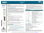
The ADTRAN Total Access 3010 HDSL Transceiver
Unit for the Central Office (LTU), part number
1182007L1, is the Central Office (CO) unit used to
deploy an HDSL E1 circuit using 4-wire metallic
facilities. See Figure 1.
61182007L1-5A
LTU
1182007L1
PWR
G703
TST
LP1
LP2
ALM
TX
E
Q
RX
TX
M
O
N
RX
ACT
GRN = NORM
YEL = MAN
A
P
S
Figure 1. ADTRAN Total Access 3010 LTU
The E1 input signal is supplied from the network via
individual G.703 lines or an E3 multiplexer. The
HDSL signals are provided to the local loop. The
Total Access 3010 LTU works in conjunction with the
ADTRAN NTU and REG to provide an E1 service up
to 9.4 km on the local loop.
The LTU works with multiple list versions of the
HDSL unit Remote end (NTU) and HDSL Range
Extender (REG) as listed below:
•
•
•
•
•
1245043Lx Low Voltage T400 REG
1245031Lx, Low Voltage T200 NTU
1245033Lx, Nx64 NTU
1245044L3, 4th Gen - T400 NTU
1245035Lx, 5th Gen - T200 NTU
The Total Access 3010 LTU can be deployed in
circuits consisting of one LTU and one NTU or in a
protection configuration requiring two LTUs and two
NTUs. When deployment requires the HDSL Range
Extender (REG), this LTU can be deployed with one
or two REGs and one NTU.
Trademarks: Any brand
names61182007L1-5,
and product names included
Section
Issue 1in this document are
trademarks, registered trademarks, or trade names of their respective holders.
1
The HDSL local loop operates as two independent
subsystems each operating over a single twisted pair.
The LTU communicates over these two twisted pairs
to the HDSL Transceiver Unit - Remote end (NTU).
Each subsystem carries half of the total bandwidth
along with a small amount of overhead used for
maintenance and performance monitoring.
NTU at less than -120 Vdc. Span powering voltages
meet all requirements of IEC 950.
System power and alarm bus connections are made
through the backplane of the Total Access 3010 shelf.
E1 and HDSL signals are connected through the 50pin shelf connectors related to each individual slot.
2. INSTALLATION
REVISION HISTORY
This is the first issue of this practice. Future changes
to this document will be summarized in this
paragraph.
C A U T I O N !
SUBJECT TO ELECTROSTATIC DAMAGE
OR DECREASE IN RELIABILITY.
HANDLING PRECAUTIONS REQUIRED.
The LTU contains onboard fuses. If a fuse opens, it
supplies a -48 Vdc voltage to the fuse alarm bus and
all front panel indicators will be Off. These fuses are
not field replaceable.
The Total Access 3010 LTU uses a DC-to-DC
converter to derive its internal logic and span
powering voltages from the -48 Vdc office supply.
The Total Access 3010 LTU can span power REGs
and NTUs as listed above. When used with REGs and
NTUs, the LTU can span power one REG and an
P2, Row A
1
2
- 48 Volt return
After unpacking the unit, inspect it for damage. If
damage is discovered, file a claim with the carrier,
then contact ADTRAN. See Warranty and Customer
Service.
The Total Access 3010 LTU occupies one line card
slot in a Total Access 3010 shelf. Power and alarm
signals are provided to the card through the backplane
of the shelf. E1 and HDSL loop signals are connected
to the mass termination shelf connectors
corresponding to the slot the unit occupies. See
Figure 2 for LTU edge connector wiring.
P2, Row B
P2, Row C
1
2
1
2
Chassis ground
Chassis ground
3
4
3
4
3
4
5
6
5
6
5
6
7
8
7
8
9
9
10
11
12
13
14
15
16
17
18
19
20
21
22
23
24
25
26
27
28
29
30
31
32
10
11
12
13
14
15
16
17
18
19
20
21
22
23
24
25
26
27
28
29
30
31
32
HDSL Loop 2 Ring (facility)
- 48 Volt DC A
- 48 Volt DC A
HDSL Loop 1 Ring (facility)
HDSL Loop 1 Tip (facility)
HDSL Loop 2 Tip (facility)
7
8
9
Fuse alarm
Receive G.703 Ring backup connection
Transmit G.703 Ring backup connection
Receive G.703 Ring normal connection
Transmit G.703 Ring normal connection
- 48 Volt return
10
11
12
13
14
15
16
17
18
19
20
21
22
23
24
25
26
27
28
29
30
31
32
Receive G.703 Tip backup connection
Transmit G.703 Tip backup connection
Receive G.703 Tip normal connection
Transmit G.703 Tip normal connection
- 48 Volt DC B
- 48 Volt DC B
Figure 2. LTU Edge Connector Wiring
2
Section 61182007L1-5, Issue 1
61182007L1-5A
3. OPERATION
Powering Options
The unit features automatic sensing based on the
current load detected on the HDSL circuit. Span
powering at less than -120 Vdc allows for span
powering of circuits without REGs or with one REG.
LTU Alarm Outputs
Pin B10 of the LTU edge connector interface provides
a fuse alarm signal that connects -48 Vdc to this pin in
the presence of a blown fuse. This indicates the card
has malfunctioned and should be replaced.
Front Panel Operation Using the Total Access
3010 SCU (P/N 1181017L1)
The front panel interface consists of a 4-character
alphanumeric LED display and a 3-position switch
that controls the display.
The switch positions are:
Center OFF
Up
MODE
Down SELECT
The switch is spring-loaded to the center (OFF)
position. The display is used to report the loop
margins (dB), and other operational conditions.
Faceplate Indicators
The Total Access 3010 LTU has seven faceplate
LEDs, illustrated in Table 1, which indicate
operational status.
The Total Access 3010 LTU plugs directly into the
Total Access 3010 shelf. No installation wiring is
required.
Table 1. Faceplate LED Indicators
LED
Indication
Description
PWR
Off
Green
Yellow
Flashing Green
Flashing Yellow
No power to card
Power present, In-Service
Power present, Out-of-Service, Maintenance or unassigned
In-Service, Card being accessed by SCU FCD
Out-of-Service, Card being accessed by SCU FCD
G703
Off
Flashing Green
Network-side E1 signal is absent or is of a format that does not match the provisioning of
the HDSL circuit
Frame bit error or CRC error detected on received E1 signal
TST
Off
Yellow
Unit is not in loopback or armed state
Local (LTU) loopback is active
LP1
Off
Red
Yellow
Green
Flashing
No synchronization between the LTU and NTU on Loop 1
Poor signal quality on Loop 1 (≤ 10-7 BER)
Marginal signal quality on Loop 1 (≤ 2 dB margin above 10-7 BER)
Good signal quality on Loop 1 (> 2 dB margin above 10-7 BER)
An error detected on either end of Loop 1 will cause this LED to blink briefly
LP2
Off
Red
Yellow
Green
Flashing
No synchronization between the LTU and NTU on Loop 2
Poor signal quality on Loop 2 (≤ 10-7 BER)
Marginal signal quality on Loop 2 (≤ 2 dB margin above 10-7 BER)
Good signal quality on Loop 2 (> 2 dB margin above 10-7 BER)
An error detected on either end of Loop 2 will cause this LED to blink briefly
ALM
Off
Red
No alarm conditions detected
Alarm condition detected either locally (LTU), or locally and remotely (LTU and NTU)
ACT
Green
Yellow
Normal operation
Manual operation
61182007L1-5A
Section 61182007L1-5, Issue 1
3
Status Mode
After selecting the LTU from the SCU, the display
enters Status mode. It alternately displays loop margin
for each HDSL loop, any active alarm condition, and
general status conditions.
T1
G.703
R1
G.703
MON
RX
The HDSL loop margin is displayed for each loop that
is active with the messages “1=xx” and “2=xx” where
xx is the HDSL loop margin for that loop. The loop
margin is held on the display for 2 seconds. The loop
margin will not be displayed if that loop is in start-up
or LOS condition.
EQ
RX
4. HDSL SYSTEM TESTING
The ADTRAN HDSL system provides extensive
ability to monitor the status and performance of the
G.703 signals and HDSL loop signals. Detailed
performance monitoring is provided by the V.24
Control Port on the ADTRAN System Controller Unit
(SCU). These features are valuable in troubleshooting
and isolating any system level problems that may
occur at installation or during operation of the HDSL
system.
LTU G.703 Bantam Jack
The LTU provides two dual Bantam jacks on the front
panel. These jacks provide a metallic splitting and
test access of the G.703 interface for connecting test
equipment to transmit and receive signals with the
LTU. See Figure 3.
HDSL Loopbacks
The E1 LTU offers five diagnostic loopbacks for use
in verifying proper data path operation. These
loopbacks are activated via the V.24 craft interface.
These loopbacks disrupt normal data transmission.
Make sure that you receive prior authorization to
place an HDSL circuit out of service prior to
activating any loopback. These loopbacks remain
active until cleared or by expiration of the loopback
timeout period. See Figure 4.
4
HDSL
LOOP 1
LTU
DATA
PUMP
EQ
TX
E1 Core Frame Mapping
The function of E1 core frame mapping is to assign
2048 kbps framed E1 data to a 2304 kbps core frame
filled with 2048 kbps data. This converts a 32-byte E1
frame into a 36-byte core frame (a ratio of 1:1.125).
The extra four bytes are filled with TSO, TS16, or
AIS data. Once the 36-byte core frame data block
reaches the HDSL loops, the data is split between the
two HDSL loop pairs.
LTU
HDSL
LOOP 1
LOOP DC
POWER SOURCE
HDSL
LOOP 2
HDSL
LOOP 2
G.703
MON
TX
T
G.703
R
Figure 3. LTU Span Powering Diagram
NTU Local Loopback
The NTU HDSL transceivers are looped back at a
point immediately before the HDSL termination. This
loopback enables a complete checkout of the NTU
data path. The NTU Local Loopback is activated via
the V.24 craft interface.
NTU Remote Loopback
The NTU HDSL transceivers are looped back at a
point immediately before the G.703 termination. This
loopback enables a complete checkout of the NTU
data path, the HDSL link, and the LTU data path. The
NTU Remote Loopback is activated via the V.24 craft
interface.
LTU Local Loopback
The LTU HDSL transceivers are looped back at a
point immediately before the HDSL termination. This
loopback enables a complete checkout of the LTU
data path. The LTU Local Loopback is activated via
the V.24 craft interface.
LTU Remote Loopback
The LTU HDSL transceivers are looped back at a
point immediately before the G.703 termination. This
loopback enables a complete checkout of the NTU
data path, the HDSL link, and the LTU data path. The
LTU Remote Loopback is activated via the V.24 craft
interface.
Section 61182007L1-5, Issue 1
61182007L1-5A
LOS2 No synchronization of LTU and NTU on
loop 2
HER1 HDSL loop1 error
HER2 HDSL loop2 error
1=XX* Loop 1 in Sync
2=XX* Loop 2 in Sync
* XX is the Signal Quality Level of the loop and
ranges from 0-20, where 0 is an indicator of poor
signal quality and 20 represents good signal quality.
LTU Network-Side Loopback
AIS
LOCAL
LOOP
G.703
LTU
G.703
X
NTU
NTU Network-Side Loopback
AIS
LOCAL
LOOP
G.703
LTU
G.703
X
NTU
NTU Customer-Side Loopback
X
LOCAL
LOOP
AIS
LTU
Display Off Mode
The display enters Display Off Mode from Status
Mode after 5 minutes with no activity on the display
switch. While in this mode, the display is completely
off.
G.703
NTU
LTU Customer-Side Loopback
X
LOCAL
LOOP
AIS
LTU
G.703
NTU
The display will return to Status Mode under the
following conditions:
• When either MODE or SELECT is activated.
Display starts again when the switch is released
• When a message other than loop margin is to be
displayed
LTU and NTU Bilateral Loopback
LOCAL
LOOP
G.703
LTU
G.703
NTU
REG Network-Side Loopback
AIS
G.703
G.703
LTU
REG
NTU
X
Dual REG Network-Side Loopback
AIS
X
G.703
X
LTU
REG
REG
NTU
G.703
X = Signal Inactive
Figure 4. HDSL Loopbacks
5. SCU CONTROL PORT OPERATION (HDSL)
The Total Access 3010 SCU provides a faceplatemounted DB-9 connector that supplies an RS-232
interface for connection to a controlling terminal. The
pinout of the DB-9 is illustrated in Figure 5. The
terminal interface operates at data rates from 1.2 kbps
to 19.2 kbps. The asynchronous data format is fixed at
8 data bits, no parity, and 1 stop bit. The supported
terminal type is VT100 or compatible.
REG Loopback
The REG HDSL transceivers are looped back toward
the LTU. This loopback enables a complete checkout
of the LTU data path, the HDSL link between the
LTU and the REG, and the REG data path. The REG
loopback is activated via the V.24 craft interface.
Front Panel
Display Message/Condition:
LLOS LTU E1 Loss of Sync
NLOS NTU E1 Loss of Sync
LERR LTU E1 error
NERR NTU E1 error
LBPV LTU E1 Bipolar violation (BPV)
NBPV LTU E1 Bipolar violation (BPV)
LOS1 No synchronization of LTU and NTU on
loop 1
61182007L1-5A
1
6
7
8
9
2
TXD (Transmit Data)
3
RXD (Receive Data)
4
5
SGN (Signal Ground)
Figure 5. RS-232 (DB-9) Pin Assignments
Section 61182007L1-5, Issue 1
5
Many portable personal computers use power-saving
programs that are known to interfere with applications
running on the personal computer. If using a portable
personal computer with terminal emulation capability,
communication between the computer and the HDSL
unit may be periodically disrupted if power-saving
programs are being used on the personal computer.
The symptoms may include misplaced characters
appearing on the screen and/or the occurrence of
screen timeouts. These symptoms are not disruptive to
the operation of the circuit and are avoidable if the
power-saving options are disabled or removed.
The screens illustrated in Figure 6 through Figure 18
are for an HDSL circuit deployed with ADTRAN’s
Low Voltage HDSL technology. The circuit includes
an LTU, NTU, and two REG. This scenario was
chosen for inclusiveness of functionality. However,
other configurations are possible, such as one REGs,
and the display will vary slightly from those shown in
this section.
Menus
For abbreviations used in the screen diagrams, see
Table 2.
Table 2. Screen Abbreviations
Abbreviation
Definition
ES
Errored Seconds
SES
Severely Errored Seconds
UAS
Unavailable Seconds
FRAMING
CCS
CAS
Unframed
Common Channel Signaling
Channel Associated Signaling
Unframed E1 Operation
CODE
HDB3
AMI
High Density Bipolar Order 3
Alternate Mark Inversion
CRC4
Cyclic Redundancy Check 4 error detection
CFM
Core Frame Mapping (Method 0, Method 1)
BPV
Bipolar Violation
S/N
Serial Number
15M
Fifteen-Minute period
24 H
Twenty-four-Hour period
Alarms
Lists current alarm condition status
0
Poor signal quality: Noise margin is -0 dB
(3 10-7 BER)
1-8
Margin measurement above 10-7 BER in dB
9
Excellent signal quality: Margin is 9 dB above 10-7 BER
6
Section 61182007L1-5, Issue 1
61182007L1-5A
Accessing the HDSL circuit information via the Total
Access SCU requires Logon and a Password using the
SCU Control Port. See Figure 6, Logon Screen.
Shelf:
77
Unacknowledged Alarms:
After successful logon, the Total Access System
Screen will appear as illustrated in Figure 7.
Total Access System
MAJOR MINOR
INFO
04/07/01 15:44
Total Access System
Account Name:
‘?’ - System Help Screen
Figure 6. Logon Screen
Shelf: 77
Unacknowledged Alarms:
Total Access System
MAJOR MINOR
INFO
04/07/01 15:45
Total Access
1.
2.
3.
4.
5.
6.
System
Common
Common
Access
System
Logoff
Controller
A - [DS3MX]
B - [DS3MX]
Modules
Alarms
Selection:
‘?’ - System Help Screen
Figure 7. Total Access Screen
61182007L1-5A
Section 61182007L1-5, Issue 1
7
From the Total Access System Screen, select Access
Modules by typing the number corresponding to the
option followed by <Enter>. This will display the
Access Module Menu Screen, illustrated in
Shelf: 77
Unacknowledged Alarms:
Figure 8, which will display the Access Modules
occupying the Total Access 3010 shelf. Select the
corresponding channel slot number for an LTU.
Total Access System
MAJOR MINOR
INFO
04/07/01 15:46
Access Module Menus
1
2
3
4
5
6
7
8
9
10
11
12
13
14
-
LTU.........
............
............
............
............
............
............
............
............
............
............
............
............
............
[Major]
[None]
[None]
[None]
[None]
[None]
[None]
[None]
[None]
[None]
[None]
[None]
[None]
[None]
15
16
17
18
19
20
21
22
-
............
............
............
............
............
............
............
............
[None]
[None]
[None]
[None]
[None]
[None]
[None]
[None]
Enter Channel Slot Number :
Inverse = Busy Modules
Figure 8. Access Module Menus Screen
8
Section 61182007L1-5, Issue 1
61182007L1-5A
This will display the ADTRAN HDSL Main Menu as
illustrated in Figure 9.
From the ADTRAN HDSL Main Menu, the following
screens can be accessed.
1. Configuration
2. Provisioning
3. Status
4. Alarms
Shelf: 1 Slot: 5
Unacknowledged Alarms:
Circuit ID:
5. Test
6. Performance Monitoring
7. Protection Configuration
8. Circuit ID
9. Alarm Options
The Configuration Screen, illustrated in Figure 10,
provides serial numbers and the manufacturing date
for each component in the HDSL circuit.
Total Access System
MAJOR MINOR
04/07/01 09:05
HDSL Line Termination Unit
1.
2.
3.
4.
5.
6.
7.
8.
9.
Configuration
Provisioning
Status
Alarms
Test
Performance Monitoring
Protection Configuration
Circuit ID
Alarm Options
Selection:
‘?’ - System Help Screen
Figure 9. HDSL Main Menu Screen
Shelf: 1 Slot: 5
Unacknowledged Alarms:
Circuit ID:
Total Access System
MAJOR MINOR
04/07/01 09:30
Configuration
Unit Name
Part Number
Serial Number
Product Revision
Software Revision
Manufacture Date
LTU
1182007L1
HW098765432109
HW
A
01/95
Unit Name
Serial Number
Product Revision
Manufacture Date
NTU
0100001481
01
10/00
Unit Name
Serial Number
Product Revision
Manufacture Date
REG1
0100748669
01
10/00
Unit Name
Serial Number
Product Revision
Manufacture Date
REG2
0100477236
01
10/00
‘?’ - System Help Screen
Figure 10. Configuration Screen
61182007L1-5A
Section 61182007L1-5, Issue 1
9
The Provisioning Screen, as illustrated in Figure 11,
displays current provisioning settings and allows for
changing the system configuration. Provisioning
changes are only allowed at the CO end of the circuit.
The unit retains the last provisioning changes to
determine its operating mode.
Shelf: 1 Slot: 5
Unacknowledged Alarms:
Circuit ID:
The Network Source Screen, illustrated in Figure 12,
allows the user to provision the unit to receive its
network signal from either MUX or a G.703 source.
Total Access System
MAJOR MINOR
04/07/01 09:06
Provisioning
1.
2.
3.
4.
5.
6.
7.
8.
9.
Framing
CRC4
Coding
G.703 Clock
Loopback Timeout
Service State
Network Source
G.703 External Alarms
Core Frame Mapping
CAS
Enabled
HDB3
Internal
None
In Service
G.703
Disabled
Method 1
Selection:
‘?’ - System Help Screen
Figure 11. Provisioning Screen
Shelf: 1 Slot: 5
Unacknowledged Alarms:
Circuit ID:
Total Access System
MAJOR MINOR
04/07/01 09:27
Network Source
1.
2.
3.
G.703
MUX A
MUX B
Selection:
‘?’ - System Help Screen
Figure 12. Network Source Screen
10
Section 61182007L1-5, Issue 1
61182007L1-5A
The Status Screen, illustrated in Figure 13, provides
quick access to status information for both the LTU
and NTU, in addition to any regenerators.
Type “3” to view the status screen for REG #1, as
illustrated in Figure 14. If the circuit involves a
second REG, press “4” from the REG #1 Status
Screen to view the REG#2 Status Screen.
Figure 13 and Figure 14 consolidate current
information for the HDSL and E1 interfaces. A key to
Shelf: 1 Slot: 5
Unacknowledged Alarms:
Circuit ID:
LTU
Loop 1 <Network> Loop 2
01 dB
01 dB
Yes
Yes
000/00000
000/00000
000/00000
000/00000
000/00000
000/00000
Loopbacks Inactive
LTU Signal Quality
[X]
9
[X]
[X]
8
[X]
[X]
7
[X]
[X]
6
[X]
[X]
5
[X]
[X]
4
[X]
[X]
3
[X]
[X]
2
[X]
[X]
1
[X]
[X]
0
[X]
1. Zero Registers
2. LTU/NTU Status
the information provided is found in the center of the
screen. Arrows indicate the key statistics, which
apply to both the remote and customer site
components.
Indications of Loopback and Sealing Current (if
present) are given at the bottom of the first key
column. Status and configuration information for the
LTU and NTU E1 signals are located in the center of
the Status Screen near the bottom.
Total Access System
MAJOR MINOR
04/07/01 09:15
LTU/NTU Status
NTU
Loop 1 <Customer> Loop 2
<Loss
->
01 dB
01 dB
<Sync
->
Yes
Yes
<-ES
15M/24H ->
000/00000
000/00000
<-SES 15M/24H ->
000/00000
000/00000
<-UAS 15M/24H ->
000/00000
000/00000
Sealing Current Present
Loopbacks Inactive
LTU E1
NTU E1
NTU Signal Quality
[X]
9
[X]
CAS
<- Frame ->
CAS
[X]
8
[X]
HDB3
<- Code ->
HDB3
[X]
7
[X]
ENABLED <- CRC4 -> ENABLED
[X]
6
[X]
METH1
<- CFM
->
METH1
[X]
5
[X]
00000
<- BPV
->
00000
[X]
4
[X]
00000
<- ES
->
00000
[X]
3
[X]
00000
<- SES
->
00000
[X]
2
[X]
00000
<- UAS
->
00000
[X]
1
[X]
None
<- Alarms ->
None
[X]
0
[X]
Selection:
3. REG1 Status
‘?’ - System Help Screen
4. REG2 Status
Figure 13. Status Screen
Shelf: 1 Slot: 5
Unacknowledged Alarms:
Circuit ID:
Total Access System
MAJOR MINOR
Loop 1 <Network> Loop 2
00 dB
00 dB
Yes
Yes
000/00000
000/00000
000/00000
000/00000
000/00000
000/00000
Loopback Inactive
[X]
9
[X]
[X]
8
[X]
[X]
7
[X]
[X]
6
[X]
[X]
5
[X]
[X]
4
[X]
[X]
3
[X]
[X]
2
[X]
[X]
1
[X]
[X]
0
[X]
1. Zero Registers
2. LTU/NTU Status
<Loss
->
<Sync
->
<-ES
15M/24H ->
<-SES 15M/24H ->
<-UAS 15M/24H ->
Sealing Current Present
04/07/01 09:14
Loop 1 <Customer> Loop 2
00 dB
00 dB
Yes
Yes
000/00000
000/00000
000/00000
000/00000
000/00000
000/00000
Loopback Inactive
____ LP1 ____ LP1 ____
____
|LTU |
|REG1|
|REG2|
|NTU |
|
|===N|
|C===|
|====|
|
|
|
|
|
|
|
|
|
|
|===N|
|C===|
|====|
|
|____|
|____|
|____|
|____|
LP2
LP2
Selection:
‘?’ - System Help Screen
[X]
9
[X]
[X]
8
[X]
[X]
7
[X]
[X]
6
[X]
[X]
5
[X]
[X]
4
[X]
[X]
3
[X]
[X]
2
[X]
[X]
1
[X]
[X]
0
[X]
3. REG1 Status
4. REG2 Status
Figure 14. REG #1 Status Screen
61182007L1-5A
Section 61182007L1-5, Issue 1
11
Predicting performance based upon signal quality
varies with each loop. Generally, a noise margin of 0
or higher will support a bit error rate (BER) of better
than 10-7. The following guidelines correspond to the
operation of the LTU faceplate LEDs labeled LP1 and
LP2. See Table 3.
Figure 15 and Figure 16 depict the HDSL Alarms
and Test Screens. Current alarm conditions are
displayed on the Alarms Screen, while a self test or
loopbacks may be initiated or terminated using the
Test Screen.
Table 3. LP1 and LP2 Guidellines
Margin
Color
Quality
Margin < 0
Red
Poor Loop Quality
0 < Margin < 2 Yellow
Marginal Loop Quality
Margin > 2
Good Loop Quality
Green
Shelf: 1 Slot: 5
Unacknowledged Alarms:
Circuit ID:
Total Access System
MAJOR MINOR
04/07/01 09:16
Alarms
NO ALARM CONDITIONS
_____
_____
_____
_____
| LTU |
|REG 1|
|REG 2|
| NTU |
|
|
|
|
|
|
|
|
--->|
|<===>|
|<===>|
|<===>|
|<—|
|
|
|
|
|
|
|
NET |
|
|
|
|
|
|
| CUST
|
|
|
|
|
|
|
|
<---|
|<===>|
|<===>|
|<===>|
|—>
|
|
|
|
|
|
|
|
|_____|
|_____|
|_____|
|_____|
‘?’ - System Help Screen
Figure 15. Alarms Screen
12
Section 61182007L1-5, Issue 1
61182007L1-5A
At each 15-minute interval, the performance
information is transferred to the 15-minute
performance data register accessed from the
Performance History screen. At each 24-hour
interval, the performance data is transferred into the
24-hour performance data register also accessed using
the Performance History screen. The Performance
History screen is shown in Figure 17.
Shelf: 1 Slot: 5
Unacknowledged Alarms:
Circuit ID:
Type the corresponding number to view the
Performance History data for customer or network
loops.
From the Status Screen, type “1” to reset the current
performance registers to zero on the Status and
Performance History Screens.
Total Access System
MAJOR MINOR
04/07/01 09:16
Test
1.
2.
3.
4.
5.
6.
7.
Selftest
Loopback
Loopback
Loopback
Loopback
Loopback
Loopback
to
to
to
to
to
to
Network
Customer
Network
Customer
Network
Network
at
at
at
at
at
at
LTU
LTU
NTU
NTU
REG-1
REG-2
=
=
=
=
=
=
Inactive
Inactive
Inactive
Inactive
Inactive
Inactive
_____
_____
_____
_____
| LTU | LP1 |REG 1| LP1 |REG 2| LP1 | NTU |
--->|-----|<=====>|-----|<=====>|-----|<=====>|-----|<—|
|
|
|
|
|
|
|
NET |
|
|
|
|
|
|
| CUST
|
| LP2 |
| LP2 |
| LP2 |
|
<---|-----|<=====>|-----|<=====>|-----|<=====>|-----|—>
|_____|
|_____|
|_____|
|_____|
Selection:
‘?’ - System Help Screen
Figure 16. Test Screen
Shelf: 1 Slot: 5
Unacknowledged Alarms:
Circuit ID:
Total Access System
MAJOR MINOR
04/07/01 09:17
LTU G.703 Performance Data
1.
2.
3.
4.
5.
6.
7.
8.
9.
10.
11.
12.
13.
14.
B.
F.
Current Error Regs
ES
SES
UAS
BPV
15 Min: 000
000
000
000
24 Hr: 00000 00000 00000 00000
Menu
LTU G.703
LTU Loop 1
LTU Loop 2
NTU G.703
NTU Loop 1
NTU Loop 2
REG1 NET Lp1
REG1 NET Lp2
REG1 CST Lp1
REG1 CST Lp2
REG2 NET Lp1
REG2 NET Lp2
REG2 CST Lp1
REG2 CST Lp2
09/21
09/20
09/19
09/18
09/17
09/16
09/15
Page back
Page forward
24 Hour History
ES
SES
UAS
----- ----- --------- ----- --------- ----- --------- ----- --------- ----- --------- ----- --------- ----- -----
BPV
-----------------------------
Selection:
‘?’ - System Help Screen
15 Minute History
ES SES UAS BPV
09:15 000 000 000 000
09:00 --- --- --- --08:45 --- --- --- --08:30 --- --- --- --08:15 --- --- --- --08:00 --- --- --- --07:45 --- --- --- --07:30 --- --- --- --07:15 --- --- --- --07:00 --- --- --- --06:45 --- --- --- --06:30 --- --- --- --06:15 --- --- --- --06:00 --- --- --- --05:45 --- --- --- --05:30 --- --- --- --Page 1
most recent data
Figure 17. Performance History Screen
61182007L1-5A
Section 61182007L1-5, Issue 1
13
The Protection Configuration Screen - Main,
illustrated in Figure 18, displays the current settings
for Protection Mode, BER Threshold and BER
Interval. The BER Threshold allows the user to select
a bit error rate that, when exceeded, will cause a
switchover to an auxiliary circuit. The BER Interval
defines the interval over which errors will be
accumulated for comparison with the BER Threshold.
Shelf: 1 Slot: 5
Unacknowledged Alarms:
Circuit ID:
The option settings for BER Threshold and BER
Interval are detailed in Table 4.
The Protection Configuration Screen – Auxiliary,
illustrated in Figure 19, displays the current settings
for Protection Mode, Minimum Hold-in Time, BER
Threshold, BER Interval, Lock-in Hours, Switch-to
-Aux Limit, and Lock-in Check Interval. A History
count for Switchovers, Reversions, Failures, and
Lockouts is provided, while the Lock-in Options and
Total Access System
MAJOR MINOR
04/07/01 09:19
Protection Configuration
1.
2.
3.
Protection Mode
BER Threshold
BER Interval
Disabled
1E-4
15
Min(s)
Selection:
‘?’ - System Help Screen
Figure 18. Protection Configuration Screen – Main
Shelf: 1 Slot: 6
Unacknowledged Alarms:
Circuit ID:
Total Access System
MAJOR MINOR
04/07/01 09:20
Protection Configuration
1.
2.
3.
4.
5.
6.
7.
Protection Mode
Minimum Hold-in Time
BER Threshold
BER Interval
Lock-in Time
Switch-to-Aux Limit
Lock-in Check Interval
Current System Status
[ Prot Disabled ]
Manual Disable
01
minutes
1E-4
15
minutes
12
hours
03
(1-9)
20
minutes
Switchovers:
Failures:
History
00
Reversions:
00
Lockouts:
00
00
Current Lock-in Option Setting
Lock-in for 12 hours if 03 switchovers occur in 20 minutes.
Selection:
‘?’ - System Help Screen
Figure 19. Protection Configuration Screen – Auxiliary
14
Section 61182007L1-5, Issue 1
61182007L1-5A
Table 4. Protection Configuration Option Settings
Protection Options
Settings
Description
Protection Mode
Auto
System automatically switches from Main to AUX with no user intervention.
Switch is initiated by loss of sync on Main or exceeding BER Threshold.
Alarms and switchover notification are generated via the SCU. Auto Mode
also allows reversion back to Main once sync is reestablished or the error
count drops below the BER Threshold.
Auto Hold
Auto Hold provides system protection identical to Auto Mode, except that
reversions are not allowed to the Main without user intervention. Once
switchover has occurred to the AUX circuit, data can only be reverted by
modifying any option on the terminal screen or by the pushbutton on the
faceplate of the LTU.
Manual Main
Manual Main requires manual switchover to the AUX circuit by user
intervention. Switchover can be accomplished via the faceplate pushbutton
or the terminal screen. The SCU will make notification of a Main circuit
failure, but will not report switchover until the data is manually switched to
the AUX circuit.
Manual AUX
Data is manually forced to the AUX circuit and will remain there until the
mode is changed via the terminal screen or by pushbutton on the faceplate.
All other option settings are ignored while in this mode.
Manual Disable
In the Manual Disable mode, the Main and AUX circuits act as two
independent units. Separate data can run on either circuit without affecting
the operation of the other. All other option settings are ignored while in this
mode.
Minimum Hold-in Time 1-99 minutes
Defines the minimum time that data will remain on the AUX circuit. This
option is only valid when in Auto or Auto Hold Protection Modes.
BER Threshold
1E-4, 1E-5, 1E-6,
1E-7
Allows the user to set the Bit Error Rate that will cause switchover from the
Main to AUX circuit when exceeded. BER Threshold can also be set from
the Main card's protection configuration and should coincide with the
settings used on the AUX card.
BER Interval
5, 10, 15 minutes
Defines the interval over which errors will accumulate for comparison with
the BER Threshold setting. BER Interval can also be set from the Main card's
protection configuration and should coincide with the settings used on the
AUX card.
Lock-in Hours
0-99
Defines duration of locking to the AUX circuit upon reaching the Switch to
AUX Limit.
Switch to AUX
Limit 1-9
Defines the number of times switch can occur from Main to AUX over the
defined Locking Check Interval before the system is locked to the AUX
circuit for the defined Locking Hours.
Lock-in Check Interval
1-99
Defines the interval over which the Switch to AUX Limit is compared before
locking in the data to the AUX circuit for the Locking Hours duration.
61182007L1-5A
Section 61182007L1-5, Issue 1
15
System Current Status are also displayed beneath the
Current Settings summary. The Current System
Status message displays the current operational state
(Normal, Switched to AUX, Locked Out, Forced to
Main, Forced to AUX, Locked to Main). The
following messages are displayed according to the
current status of the protection system.
• NORMAL OPERATION – Unit is in AUTO
mode with data passing over the MAIN circuit.
• SWITCHED TO AUX – Data has been switched
to the AUX circuit because of an auto switch or
the protection mode has been set to MANUAL
AUX.
• LOCKED OUT – The system has violated the
lock-in option settings and has locked data to the
AUX circuit for the user-defined lock-in hours.
• FORCED TO MAIN – The MAIN unit’s button
has been pressed once and is forced online. An
additional press of the MAIN unit’s button will
revert to software control.
• FORCED TO AUX – the AUX unit’s button has
been pressed once and is forced online. An
additional press of the AUX unit’s button will
revert to software control.
• LOCKED TO MAIN – The protection mode is
set to MANUAL MAIN which doesn’t auto
switch to the AUX circuit but relies on manual
intervention to switch the data to the AUX
circuit; however, alarm indications will be
updated.
A detailed description of the Protection Configuration
parameter settings is included in Table 3.
Shelf: 1 Slot: 5
Unacknowledged Alarms:
Circuit ID:
The Protection Configuration Screen – Auxiliary also
displays a history of switching occurrences. The
following conditions are shown with a history count
of occurrences:
• Switchovers – Number of times data has been
switched from the Main to the Auxiliary circuit.
Switchovers will only occur in the Auto and Auto
Hold protection modes.
• Reversions – Number of times data has been
switched from the Auxiliary back to the Main
circuit. Reversions will only occur in the Auto
protection mode.
• Failures – Number of times the APS system has
attempted to switch data from either the Main to
Auxiliary circuit or from the Auxiliary to Main
circuit. A failure would typically occur as a
result of an HTU-R in the circuit that was not
compatible for APS service. Only the
1245026LX HTU-R’s should be used when
deployed in APS circuits. Failures can occur in
any protection mode.
• Lockouts – Number of times a lockout has
occurred due to the number of APS switches
exceeding the Switch to AUX Limit over the
preset Lock-in Check Interval. Lockouts can
only occur in Auto or Auto Hold protection
modes.
Figure 20 illustrates the Set Circuit ID Screen. The
Circuit ID can be defined using up to 25 characters,
and will be displayed on each of the Total Access
HDSL Screens.
Total Access System
MAJOR MINOR
04/07/01 09:21
Set Circuit ID
Enter ID:
‘?’ - System Help Screen
Figure 20. Set Circuit ID Screen
16
Section 61182007L1-5, Issue 1
61182007L1-5A
Figure 21 illustrates the Alarm Options Screen. This
option allows the user to first set a 15-minute
threshold for both ES and SES alarms and
subsequently to categorize the crossing of those
thresholds as a MINOR or MAJOR alarm. Setting a
threshold to 900 will disable it.
6. HDSL DEPLOYMENT GUIDELINES
The ADTRAN HDSL system is designed to provide
E1 services over loops designed to comply with ETSI
guidelines. Deployment guidelines are given below.
1. All loops are non-loaded only.
2. For loops with 0.4 mm cable, the maximum loop
length including bridged tap lengths is 2.7 km.
3. For loops with 0.5 mm cable, the maximum loop
length including bridged tap lengths is 4.7 km.
4. Any single bridged tap is limited to 500 m.
5. Maximum number of bridged taps is 2.
Shelf: 1 Slot: 5
Unacknowledged Alarms:
Circuit ID:
1.
2.
3.
4.
7. MAINTENANCE
The ADTRAN Total Access LTU requires no routine
maintenance. In case of equipment malfunction, use
the faceplate Bantam jack connectors to help locate the
source of the problem.
ADTRAN does not recommend that repairs be
performed in the field. Repair services may be obtained
by returning the defective unit to the ADTRAN
Customer Service RMA Department.
Total Access System
MAJOR MINOR
04/07/01 09:22
Alarm Options
Current Settings
ES Alarm Level
SES Alarm Level
ES Alarm Threshold
SES Alarm Threshold
=
=
=
=
Major
Major
000
000
Selection:
‘?’ - System Help Screen
Figure 21. Alarm Options Screen
61182007L1-5A
Section 61182007L1-5, Issue 1
17
8. PRODUCT SPECIFICATIONS
Product specifications are detailed in Table 4.
Table 5. Total Access 3000 LTU Specifications
Loop Interface
Modulation Type ............................... 2B1Q
Mode .................................................. Full Duplex, Echo Canceling
Number of Pairs ................................. Two
Bit Rate .............................................. 1168 kbps per pair
Baud Rate .......................................... 584K baud per pair
Service Range .................................... 2.7 km over 0.4 mm cable;* 4.7 km over 0.5 mm cable*
Loop Loss .......................................... 27 dB maximum @ 150 kHz
Bridged Taps ..................................... 2 Taps, 500 meters maximum each
Performance ....................................... Compliant with ETSI TS 135 101
HDSL Tx Signal Level ...................... 13.5 dBm
Input Impedance ................................ 135 Ω
Return Loss ........................................ 20 dB (40 kHz to 200 kHz)
Network Interface
4-wire E1 ........................................... 2.048 Mbps CCITT G.703 and G.704 compatible
E1 Output Level ................................ 0 dB
Impedance .......................................... 75 or 120 Ω
E1 Core Frame ................................... Method 0, Method 1 (see Section 5)
E1 Line Code ..................................... AMI, HDB3
E1 Format .......................................... CCS, CAS, Unframed
E1 Error Checking ............................. CRC4
Power
Total Power ....................................... -48 Vdc @ 10 W typical
E1 LTU Power Dissipation ............... <7 W maximum
E1 LTU -48 Vdc Current Drain ......... < .3 A maximum
Sealing Current .................................. current limited at 10 mA
Span Power ........................................ -120 Vdc (internally generated) current limited at 60 mA (CE compliant)
Clock
Clock Sources .................................... Internal, E1 Derived
Internal Clock Accuracy .................... + 25 ppm (Stratum 4)
Tests
Diagnostics ........................................ Self-Test, Local Loopback (LTU), Remote Loopback (NTU)
Physical
Dimensions ........................................ 6 in. (152.4 mm) high x 5/8 in. (15.9 mm) wide x 10 in. (254 mm) deep
Weight ............................................... Less than 1 lb.
Environment
Temperature ....................................... Operating (Standard): -40°C to +70°C; Storage: -40°C to +85°C
Safety ................................................. In conformance with EN41003 and EN60950, IEC 950
Overvoltage Protection ...................... In conformance with CCITT K.20
EMC .................................................. In conformance with EN55022 and EN50082
Part Number
Total Access LTU .............................. 1182007L1
18
Section 61182007L1-5, Issue 1
61182007L1-5A
9. WARRANTY AND CUSTOMER SERVICE
ADTRAN will replace or repair this product within
five (5) years from the date of shipment if it does not
meet its published specifications or fails while in
service. (See ADTRAN International Equipment
Warranty, document 60000003-3).
Contact Customer And Product Services (CAPS) prior
to returning equipment to ADTRAN.
For service, CAPS requests, or further information,
contact one of the following numbers:
ADTRAN, Inc.
Attention: International Department
901 Explorer Boulevard
Huntsville, Alabama 35806
USA
www.adtran.com
Canada - Quebec
1 877 923-8726 toll free
1 514 940-2888 voice
1 514 940-2890 fax
[email protected]
Canada - Other Provinces
1 877 923-8726 toll free
[email protected]
Europe - Zurich, Switzerland
41 1 880 27 77 voice
41 1 880 27 78 fax
[email protected]
Latin America
1 954 746-5355 voice
1 954 746-7540 fax
[email protected]
Asia Pacific - Hong Kong
852 2824-8283 voice
852 2824-8928 fax
[email protected]
Mexico/Caribbean
1 954 577-0357 voice
1 954 577-0358 fax
[email protected]
Canada - Ontario
1 416 290-0585 voice
1 416 296-1259 fax
[email protected]
U. S. Headquarters
1 256 963-2500 voice
1 256 963-6300 fax
1 256 963-8200 fax back
[email protected]
61182007L1-5A
Section 61182007L1-5, Issue 1
19
20
Section 61182007L1-5, Issue 1
61182007L1-5A
Appendix A
HDSL H-LSS Circuit Configuration and Turnup
for G.703 Fed Systems
Introduction
This section provides step-by-step instructions for the
configuration and turnup of an HDSL Loop Support
System (H-LSS) circuit on an HDSL loop fed from
the network via individual G.703. Configuration
procedures include installing appropriate line and
remote cards, configuring the Total Access LTU cards
for protection switching operation and enabling the
protection switching feature.
Protection pairs on the Total Access 3010 system are
adjacent odd-even slots, indicated on the Total Access
3010 front shelf screening. The odd slot on the left is
the MAIN circuit; the even slot to the right is the
AUX, or backup circuit.
Prerequisite Procedures
Before beginning the configuration and turnup
procedure described in this NTP, the user should
ensure that a Total Access 3010 shelf is properly
installed and wired for G.703 network feeds. Also,
ensure the SCU is installed and provisioned.
NOTE
Valid protection pairs are the adjacent odd-even
slots in the Total Access 3010 shelf, and are
further designated by the “brackets” on the lower
front silkscreen of the Total Access 3010 chassis.
The left (odd-numbered) slot in the pair is the
MAIN; the right (even-numbered) slot is the
AUX circuit for the pair. Thus, Slots 1 and 2 are
a valid protection pair, but Slots 6 and 7 are not.
The pair must have the odd-numbered slot to the
left in the pair.
NOTE
This procedure assumes that the technician
turning up the protected circuit knows which
pair of slots has been assigned to the circuit, and
that a single G.703 signal from the appropriate
source, generally a G.703 cross connect, has
been routed and wired to the appropriate pairs of
pins on backplane connectors labeled Pair 7 and
Pair 8. For a protected circuit, the appropriate
pin pairs that should receive the G.703 from the
network are the odd numbered pins
corresponding to the MAIN, odd numbered slot.
61182007L1-5A
Materials Required
• Total Access 3010 chassis installed and wired,
with SCU.
• Two Total Access 3010 LTUs.
• Two protection switching capable NTUs. These
NTUs are the following - 1246035L1 T200
mechanics.
• One dual-slot remote housing, ADTRAN P/N
1245034L2.
1. INSTALL THE LTUs INTO TOTAL ACCESS
3010
Electronic modules can be damaged by static
electrical discharge. Before handling modules, wear
an antistatic discharge wrist strap to prevent damage
to electronic components. Place modules in antistatic
packing material when transporting or storing. When
working on modules, always place them on an
approved antistatic mat that is electrically grounded.
1.1 Gently but firmly push the LTU into the
appropriate odd-numbered slot (which will be
the MAIN HDSL circuit). Compatible slots
can be any slot pair that starts with an odd
number (MAIN) and includes the adjacent (to
the right) even-numbered slot (AUX).
Compatible slot pairs are further designated
by the bracket notation around the slot pairs
on the silk screen just below the physical slots
on the front of the Total Access 3010.
Simultaneous thumb pressure at the top
(above the PWR LED) and bottom (below the
ACT LED) of the unit will ensure a good seat
of the LTU pins into the backplane connector.
Repeat this step for the AUX LTU to be
installed in the adjacent (even, to the right)
slot.
1.2 Push the ejector tab up and closed against
the LTU faceplate.
2. PROVISION THE LTU
If Module Auto-Provisioning is enabled on the SCU,
and if the new cards are of the same type as the
former, the provisioning of the former access cards of
the two Total Access 3010 slots will be written to the
new access cards upon installation.
Section 61182007L1-5, Issue 1
A-1
If this is an initial installation, the units will require
provisioning to appropriately configure them out of
the factory default states.
2.1 Logon to Total Access system.
2.2 Check to ensure the LTU line cards are
correctly provisioned according to circuit
parameters. Under the Provisioning menu, set
numbered option, Network Source, to G.703.
This option causes the LTU to look to the
individual G.703 backplane connector for its
data feed.
2.3 Ensure the provisioning of both the
MAIN and AUX LTUs is identical,
except for the following options:
a. Provision the MAIN unit to OUT OF
SERVICE-MAINTENANCE (OOS-M)
mode.
b. Provision the AUX unit to the OUT OF
SERVICE-UNASSIGNED (OOS-U) mode.
2.4 Enable protection switching
a. Access the MAIN Menu of the LTU in the
odd-numbered (MAIN) slot.
b. Select Option 7, Protection
Configuration.
c. Select Option 1, Protection Mode.
d. To enable protection switching, select
Option 1, ENABLE.
NOTE
Unless the AUX circuit is in the OOS-U mode,
the operator will not be able to change the
Protection mode of the MAIN LTU.
e. Set Options 2 and 3, BER Threshold and
BER Interval (see Table 3 in the
Installation and Maintenance practice for
definitions).
f. Back out of the menu for the MAIN slot
and access the LTU in the even-numbered
(AUX) slot.
g. Select Option 7, Protection Configuration.
h. Option 1, Protection Mode, will have been
set to AUTO. If you desire to provision a
different H-LSS mode, select Option 1,
and choose between Auto, Manual AUX,
Manual Main, and Auto Hold.
i. Set Options 2-7 as desired on the AUX
unit.
A-2
2.5 From the provisioning menu of the AUX
circuit, reset the AUX unit to OOS-M.
2.6 Logoff the system
a. From the Total Access Menu, select
Option 7, Logoff, and press <Enter>.
b. From the Exit and Logoff screen, select
“Y” and press <Enter>.
3. INSTALL THE DUAL-SLOT STANDALONE
HOUSING
See the associated Installation and Maintenance
practice, P/N 61245034L2-5, for mounting and wiring
instructions.
4. INSTALL THE NTU
The NTU terminates local loop HDSL signals
originating from the Central Office (CO) unit and
transforms the HDSL signal into traditional G.703
signals to be delivered to the customer.
4.1 Install the NTU into the Dual-Slot
Remote Housing
Electronic modules can be damaged by static
electrical discharge. Before handling modules,
wear an antistatic discharge wrist strap to
prevent damage to electronic components.
Place modules in antistatic packing material
when transporting or storing. When working
on modules, always place them on an
approved antistatic mat that is electrically
grounded.
4.1.1
4.1.2
4.1.3
Section 61182007L1-5, Issue 1
Connect the individual 4-wire HDSL
circuits to the HDSL terminal block
inside the Dual slot remote housing.
The 4-wire MAIN circuit will connect
to the Loop 1 and Loop 2 terminals
labeled “MAIN” and the 4-wire AUX
circuit will connect to the Loop 1 and
Loop 2 terminals labeled “AUX.”
Gently but firmly push the NTU
into the lower dual slot remote
housing slot. Repeat this step for the
second NTU in the upper slot.
The LTUs will transfer provisioning
data to the NTUs upon power up.
Some provisioning of the NTU,
however, may be necessary due to
hardware DIP switches and jumpers.
See the Installation and Maintenance
practice for the specific NTU utilized
by your company.
61182007L1-5A
4.1.4
Upon provisioning of the NTUs,
the faceplate LEDs should read as
shown in Table 1.
NOTE
The condition of the ALM, G.703 and G.703
LEDs depends upon the status of the equipment
on the ends of the installed circuit. If both
terminations of the circuit are appropriately
configured and prepared to pass data, the LTU
ALM LEDs will be out, the LTU G.703 LEDs
will be green (MAIN) and Off (AUX), the MAIN
NTU G.703 LED will be green and ALM off,
while the AUX NTU G.703 will be off, and
ALM red.
5. RESET ALL EQUIPMENT TO OPERATING
CONDITION
When the customers at both ends of the circuit have
turned up their equipment and are running data (or test
patterns, or are in loopbacks, or some other condition
that will preclude the generation of alarms), the LTUs
can be placed In Service to restore the alarm
generating functions of the equipment to the network.
5.1 From the Total Access 3010 LTU
Provisioning Screen for both the MAIN and
AUX LTUs, select the Service State option,
and place both LTUs In Service.
NOTE
Placing the LTUs In Service will change the
PWR LED from slow flashing green to steady
green.
6. DISABLING PROTECTION SWITCHING
Disabling the protection switching mode from the
circuit converts both the MAIN and AUX circuits into
independent standalone HDSL circuits.
61182007L1-5A
CAUTION
Ensure that data has been removed from the
AUX circuit before proceeding with the next
step. Disabling PROTECTION SWITCHING
before removing data from the AUX Loop will
cause a loss of signal condition on that loop.
Under normal circumstances, the data on the
HLSS circuit will be running on the MAIN
HDSL circuit, and this precaution is unnecessary.
6.1 Disabling Protection Switching
a. Access the AUX LTU and select Option 2,
Provisioning, from the HDSL Main Menu.
b. From the Provisioning menu, choose the
Service State option.
c. Select Option 3, Out Of Service-Unassigned.
d. Escape out of the AUX LTU menus and
proceed to the MAIN LTU menu.
e. From the Main Menu, select Option 7,
Protection Configuration.
f. From the Protection Configuration menu,
select Option 1, Protection Mode.
g. Choose Option 2, Disable.
NOTE
There is no provisioning required at the NTUs to
remove protection-switching capability. Upon
completion of the above procedure, the MAIN
circuit is an independent, non-protected HDSL
circuit. The AUX circuit is also now independent,
with protection switching disabled, and currently
OOS-U.
6.2 Adjust Wiring at Dual Remote Housing
Once protection switching has been disabled in the
LTUs, the housing is internally wired to provide a
G.703 signal to both the MAIN G.703 and
AUXILIARY/TEST G.703 RJ-48 jacks. Connect the
customer’s equipment to the AUX RJ-48 jack or the
AUX G.703 terminal strip in the housing to complete
a second independent HDSL circuit.
Section 61182007L1-5, Issue 1
A-3
A-4
Section 61182007L1-5, Issue 1
61182007L1-5A
Appendix B
HDSL H-LSS Circuit Configuration and Turnup
for DS3-Fed Systems
1. UNPACK AND INSPECT THE THE TOTAL
ACCESS DS3 MUX MODULES
Each DS3 MUX Module is shipped in its own
cardboard shipping carton. Open the carton carefully
and avoid puncturing the carton with sharp objects.
After removing the unit from the carton, unwrap the
antistatic bubble-wrap and pull the unit from the
protective plastic bag.
After unpacking the unit, inspect it for damage. If
damage is discovered, file a claim with the carrier,
then contact ADTRAN. See Warranty and Customer
Service.
2. INSTALL THE DS3 MUX MODULES
2.1. Install the DS3 MUX Module into Total
Access 3010. Electronic modules can be
damaged by static electrical discharge. Before
handling modules, wear an antistatic
discharge wrist strap to prevent damage to
electronic components. Place modules in
antistatic packing material when transporting
or storing. When working on modules, always
place them on an approved antistatic mat that
is electrically grounded.
The procedure below assumes that the DS3
MUX is being newly installed into the Total
Access 3010. If the MUX is already up and
running, begin with Step 2.1.2.
2.1.1. Gently but firmly push the DS3 MUX
into the second slot, slot A, at the left
end of the shelf. Simultaneous thumb
pressure at the top (above the POWER
LED) and bottom (below the Test/
Enable button) of the unit will ensure a
good seat of the DS3 pins into the
backplane connector. Push the ejector
tab up and closed against the DS3 `
faceplate.
61182007L1-5A
2.1.2 Ensure that MUX A is in the Out of
Service-Maintenance (OOS-M)
mode. Placing the MUX in OOS-M
will prevent the MUX from
generating alarms back to the
network, and will allow loopbacks to
be initiated and taken down. Data
traffic on other embedded G.703
circuits will not be disturbed. Note
that while the DS3 MUX is in the
OOS-M mode, no alarms will be
passed to the network, including those
of circuits that may already be in
service on the MUX. After the APS
circuit is turned up, be sure to reset the
MUX to the In Service (IS) mode as
indicated in Step 6.0.1 to regain alarm
notification.
NOTE
If a single multiplexer module is used, skip Step
2.1.3. For redundant MUX applications, continue
with 2.1.3 below. When using a single
multiplexer, disregard all references to the
Offline MUX.
2.1.3 Ensure that Linked Provisioning is
“Enabled” on MUX A, and install the
second MUX in Slot B of the Total
Access 3010, using Steps 2.1.1 and
2.1.2 above for the B slot MUX. This
will allow MUX B to be configured as
MUX A when MUX B is installed.
Linked Provisioning is factory
defaulted to Enable, however, Linked
Provisioning does not affect Service
States. The factory default Service
State for MUX B is Out of
Service-Unassigned. Both muxes are
now to be configured identically, and
in the OOS-M service state. At this
point, faceplate LED indicators for
MUX A (Online) and MUX B
(Offline) will be as in Table B-1.
Section 61182007L1-5, Issue 1
B-1
For this procedure, the technician
needs to know which embedded G.703
in the incoming DS3 data stream to
map to the appropriate APS slot in the
Total Access 3010. Do not continue
without this information. In a newly
installed DS3 MUX, thathas not been
changed from factory defaults, the
embedded G.703s in the DS3 will be
mapped to the like-numbered slot (i.e.
G.703#1 to Slot 1, G.703#2 to Slot 2,
up to G.703#28 to Slot 28).
a. Access the Main Menu of the
DS3 MUX module and select
Option 8, Channel Mapping.
b. At the bottom of the screen where
you see “Selection or Enter
Mapping (E1#/Slot#)”, enter the
number of the embedded G.703
followed by “/” and the
appropriate slot number, then
<Enter>. This action will assign
the desired G.703 to the slot in the
Total Access 3010.
Table B-1. Faceplate LED Indicators
ONLINE
POWER - Yellow
STATUS - Green
TEST - Off
LOCKOUT - Off
ONLINE - Green
OFFLINE
POWER - Yellow
STATUS - Green
TEST - Off
LOCKOUT - Off
ONLINE - Off
NOTE
Only one DS3 MUX is required for any data
circuit to be operational. Two modules are used
for electronics redundancy of the DS3 circuit.
2.2 Provision the DS3 MUX
NOTE
There are no settings on the SCU that will affect
APS operation of either the DS3 MUX units or
the LTU line cards.
2.2.1 Logon to Total Access system.
2.2.2 If you are building a new DS3 circuit,
provision the DS3 MUX modules
according to circuit parameters. If the
HDSL H-LSS circuit is to be turned up
in an existing Total Access 3010 with
DS3 feed, assume that the parameters
have already been set for the DS3
circuit. Disregard this step and
continue.
2.2.3 When channel mapping the DS3 MUX
to individual slots configured for
protection switching, it is necessary to
map a channel only to the MAIN (oddnumbered) slot. If a fault condition
occurs and a protection switch is made
from the MAIN circuit to the AUX
circuit, the channel is temporarily
mapped by the DS3 MUX into the
AUX (even-numbered) slot and a
Failure notice attached to the MAIN
(odd) slot. Follow the steps below for
mapping a channel to the MAIN slot.
B-2
WARNING
Assigning the incorrect embedded G.703 from
the DS3 to a slot in the Total Access 3010 could
disrupt existing traffic.
2.2.4
APS configuration of the DS3 MUX
units is NOT required for the LTUs to
be in H-LSS configuration. The two
APS configurations operate
independently of each other.
NOTE - APS Faceplate Pushbutton 1. When activated with the Test/Enable switch
on the Offline unit, it forces a switch to protection.
(Offline MUX becomes Online MUX).
2. When activated with the Test/Enable switch
from the ONLINE unit, it toggles the APS
Lockout Status.
Section 61182007L1-5, Issue 1
61182007L1-5A
3. INSTALL THE LTU
The Total Access 3010 LTU delivers an E1 signal
over an HDSL local loop. The local loop in the H-LSS
configuration includes two independent 4-wire
circuits. The two LTUs communicate to their
respective remote units, the NTUs. When an H-LSS
switch occurs, the AUX circuit takes over transmitting
the data load from the MAIN circuit until the MAIN
circuit is restored.
3.1
Install The LTUs into Total Access
3010
Electronic modules can be damaged by static
electrical discharge. Before handling modules,
wear an antistatic discharge wrist strap to
prevent damage to electronic components.
Place modules in antistatic packing material
when transporting or storing. When working
on modules, always place them on an
approved antistatic mat that is electrically
grounded.
3.1.1 Gently but firmly push the LTU into
the appropriate odd-numbered slot
(which will be the MAIN HDSL
circuit). Compatible slots can be any
slot pair that starts with an odd number
(MAIN) and includes the adjacent (to
the right) even-numbered slot (AUX).
Compatible slot pairs are further
designated by the bracket notation
around the slot pairs on the silk screen
just below the physical slots on the
front of the Total Access 3010.
Simultaneous thumb pressure at the
top (above the PWR LED) and bottom
(below the ACT LED) of the unit will
ensure a good seat of the LTU pins
into the backplane connector. Repeat
this step for the AUX LTU to be
installed in the adjacent (even, to the
right) slot.
3.1.2 Push the ejector tab up and closed
against the LTU faceplate.
3.2
Provision the LTU
If Module Auto-Provisioning is enabled on
the SCU, and if the new cards are of the same
type as the former, the provisioning of the
former access cards of the two Total Access
3010 slots will be written to the new access
cards upon installation.
61182007L1-5A
If this is an initial installation, the units will
require provisioning to appropriately
configure them out of the factory default
states.
3.2.1 Logon to Total Access system.
3.2.2 Check to ensure the LTU line cards are
correctly provisioned according to
circuit parameters. Under the
Provisioning Menu, set numbered
option, Network Source, to Auto
MUX. This option causes the LTU to
look to the ON-LINE MUX for its data
in the event of a protection switch
between the MUX modules.
3.2.3 Ensure the provisioning of both the
MAIN and AUX LTUs is identical,
except for the following options:
a. Provision the MAIN unit to
OOS-M mode.
b. Provision the AUX unit to the
OOS-U mode.
3.2.4 Enable protection switching.
a. Access the MAIN Menu of the
LTU in the odd-numbered (MAIN)
slot.
b. Select Option 7, Protection
Configuration.
c. Select Option 1, Protection Mode.
d. To enable protection switching,
select Option1, Enable.
Unless the AUX circuit is in the
OOS-U mode, the operator will
not be able to change the
Protection mode of the MAIN
LTU.
e. Set Options 2 and 3, BER
Threshold and BER Interval (see
Table 2).
f. Back out of the menu for the
MAIN slot and access the LTU in
the even-numbered (AUX) slot.
g. Select Option 7, Protection
Configuration.
h. Option 1, Protection Mode, will
have been set to AUTO. If you
desire to provision a different
H-LSS mode, select Option 1, and
choose between Auto, Manual
AUX, Manual Main, or Auto Hold.
i. Set Options 2-7 as desired on the
AUX unit. (see Table 2).
Section 61182007L1-5, Issue 1
B-3
3.2.5 From the provisioning menu of the
AUX circuit, reset the AUX unit to
OOS-M.
3.2.6 Logoff the system.
a. From the Total Access Menu,
select Option 7, Logoff, and press
<Enter>.
b. From the Exit and Logoff screen,
select “Y” and press <Enter>.
4. INSTALL THE DUAL-SLOT STANDALONE
HOUSING
See the associated Installation and Maintenance
practice, P/N 61245034L2-5, for mounting and wiring
instructions.
5. INSTALL THE NTU
The NTU terminates local loop HDSL signals
originating from the Central Office (CO) unit and
transforms the HDSL signal into traditional E1 signals
to be delivered to the customer.
5.1 Install the NTU into the Dual-Slot
Remote Housing
Electronic modules can be damaged by static
electrical discharge. Before handling modules,
wear an antistatic discharge wrist strap to
prevent damage to electronic components.
Place modules in antistatic packing material
when transporting or storing. When working
on modules, always place them on an
approved antistatic mat that is electrically
grounded.
5.1.1 Connect the individual 4-wire HDSL
circuits to the HDSL terminal block
inside the Dual slot remote housing.
The 4-wire MAIN circuit will connect
to the Loop 1 and Loop 2 terminals
labeled “MAIN” and the 4-wire AUX
circuit will connect to the Loop 1 and
Loop 2 terminals labeled “AUX”.
5.1.2 Gently but firmly push the NTU into
the lower dual slot remote housing
slot. Repeat this step for the second
NTU in the upper slot.
5.1.3 The LTUs will transfer provisioning
data to the NTUs upon power-up.
Some provisioning of the NTU,
however, may be necessary due to
hardware DIP switches and jumpers.
B-4
See the Installation and Maintenance
practice for the specific NTU utilized
by your company.
5.1.4 Upon provisioning of the NTUs, the
faceplate LEDs should read as shown
in Table 3.
NOTE
The condition of the ALM, DSX and E1 LEDs
depends upon the status of the equipment on the
ends of the installed circuit. If both terminations
of the circuit are appropriately configured and
prepared to pass data, the LTU ALM LEDs will
be out, the LTU DSX LEDs will be green, the
MAIN NTU E1 LED will be green and ALM
off, while the AUX NTU E1 will be off, and
ALM red.
6. RESET ALL EQUIPMENT TO OPERATING
CONDITION
When the customers at both ends of the circuit have
turned up their equipment and are running data (or test
patterns, or are in loopbacks, or some other condition
that will preclude the generation of alarms), the LTUs
and DS3 MUX can be placed In Service to restore the
alarm generating functions of the equipment to the
network.
6.0.1
6.0.2
From the Total Access 3010 DS3 MUX
Provisioning Screen, select Option 4,
Service State, and place the DS3
MUX into In Service. If dual
multiplexers are being utilized, place
MUX B In Service.
From the Total Access 3010 LTU
Provisioning Screen for both the MAIN
and AUX LTUs, select the Service State
option, and place both LTUs In Service.
Placing the DS3 multiplexers In Service will change
the Power LED from yellow to green. Placing the
LTUs In Service will change the PWR LED from slow
flashing green to steady green.
7. DISABLING PROTECTION SWITCHING
Disabling the protection switching mode from the
circuit converts both the MAIN and AUX circuits into
independent standalone HDSL local loops.
Section 61182007L1-5, Issue 1
61182007L1-5A
NOTE
Ensure that data has been removed from the
AUX circuit before proceeding with the next
step. Disabling protection switching before
removing data from the AUX loop will cause a
loss of signal condition on that loop. Under
normal circumstances, the data on the H-LSS
circuit will be running on the MAIN HDSL
circuit, and this precaution is unnecessary.
NOTE
G.703 DS3 multiplexer channel mapping to the
even-numbered (formerly AUX) slot in the Total
Access 3010 chassis will not automatically be
restored. Assignment of an embedded G.703 in
the DS3 data stream to the even slot will have to
be made prior to using the slot as a DS3-fed
HDSL circuit.
7.0.1 Disabling protection switching.
a. Access the AUX LTU and select
Option 2, Provisioning, from the
HDSL Main Menu.
b. From the Provisioning Menu,
choose the Service State option.
c. Select Option 3, Out Of
Service-Unassigned.
d. Escape out of the AUX LTU
menus and proceed to the MAIN
LTU Menu.
e. From the Main Menu, select
Option 7, Protection
Configuration.
f. From the Protection Configuration
menu, select Option 1, Protection
Mode.
g. Choose Option 2, Disable.
NOTE
There is no provisioning required at the NTUs to
remove protection switching capability. Upon
completion of the above procedure, the MAIN
circuit is an independent, non-protected HDSL
circuit. The AUX circuit is also now independent,
with protection switching disabled, and currently
OOS-U.
7.0.2 Adjust wiring at Dual remote housing.
Once protection switching has been
disabled in the LTUs, the housing is
internally wired to provide an E1signal
to both the MAIN E1 and
AUXILIARY/TEST E1 RJ-48 jacks.
Connect the customer’s equipment to
the AUX RJ-48 jack or the AUX E1
terminal strip in the housing to
complete a second independent HDSL
circuit.
61182007L1-5A
Section 61182007L1-5, Issue 1
B-5
B-6
Section 61182007L1-5, Issue 1
61182007L1-5A