1
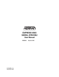
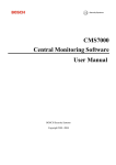
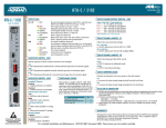
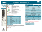
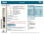
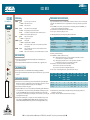
JOBAID
DS3 MUX
DS3 MX
CLEI: M3CMSP0E_ _
DS3MX
1181020L1
POWER
STATUS
TEST
STATUS LEDs
●
●
●
STATUS
●
●
●
●
TEST
●
●
LOCKOUT ●
●
●
POWER
ONLINE
61181020L1-22A
0008
PROVISIONING THE DS3 MULTIPLEXER
OFF
YELLOW
GREEN
OFF
GREEN
RED
YELLOW
OFF
YELLOW
OFF
YELLOW
RED
● OFF
● GREEN
No power is present on the unit
Unit is Out-of-Service
Unit is In-Service
Unit is Out-of-Service, Unassigned
DS3 signal is present and synchronized
Local alarm or local and remote alarm condition detected
Remote alarm condition detected
Unit is not in loopback
Loopback active
APS enabled
APS disabled due to INHIBIT
APS is locked out due to three non-forced APS events within a
24-hour period
Unit is stand-by unit (unit receives from network but does not
transmit to network)
Unit is on-line unit (unit receives from and transmits to network)
To provision the DS3 Mux, connect a terminal emulator via the RS-232 (DB-9) connector on the faceplate
of the SCU. The terminal must be VT-100 or compatible and set for 9600 bps, 8 data bits, no parity and 1
stop bit.
■ At the LOGON screen, enter the system password. Note the default password is “PASSWORD” (case
sensitive) and can be changed upon initial login.
■ Select Common A or Common B from the Total Access Menu.
■ Select option 2, Provisioning, and press <enter>.
The following table lists the provisioning settings and their default values.
Options
Framing
Line Build Out
Clock Source
Service State
Linked Provisioning
Line Code
■
APS PUSHBUTTON
■
LOCKOUT
ON LINE
APS
TEST/
ENABLE
■
When depressed simultaneously with the Test/Enable switch on the Off-line unit, a
protection switch is forced.
When depressed with the Test/Enable switch on the On-line unit, it toggles APS status.
■
■
TEST/ENABLE BUTTON
■
■
When depressed alone, tests all unit LEDs (multicolor LEDs appear YELLOW).
When depressed simultaneously with the APS switch on the Off-line unit, a protection switch
is forced.
■
■
■
■
Ensure the TA 3000 system chassis is properly mounted and wired for power. BNC Adapter
Module, P/N 1181004L1, is required for DS3 operation. The adapter is mounted to connector
J34 (J20 on 19” shelf), located in the lower right corner of the backplane.
Ensure SCU is seated and receiving power.
Plug DS3 module into slot A or B of system chassis. Gently but firmly push the DS3 Mux into
one of the Mux slots, A or B, at the left end of the shelf. Simultaneous thumb pressure at the
top (above the POWER LED) and bottom (below the Test/Enable button) of the unit will
ensure a good seat of the DS3 pins into the backplane connector. Push the ejector tab up and
closed against the DS3 faceplate.
Allow the self-test LED sequence to complete. The self- test should take about 40 seconds.
Upon completion, the POWER LED will be YELLOW, indicating the unit is Out-of-Service
and the STATUS LED will be OFF indicating the unit is in the Unassigned (OOS-UA) state.
Service
State
OOS, Un
OOS, Ma
In Service
■
■
Default
M13, C-Bit, Auto detect
Short, Long
Local, Loop
In Service, OOS-Unassigned, OOS-Maint
Enabled, Disabled
B3ZS (cannot be changed)
Auto detect
Short
Loop
OOS-Unassigned
Enabled
B3ZS
Framing - sets the DS3 framing.
Line Build Out - set LBO to either Short or Long.
Short - cable length is less than 225 feet of 734A or equivalent coaxial cable or less than
100 feet of Lucent 735 or equivalent coaxial cable.
Long - cable length is greater than 225 feet of 734A or equivalent coaxial cable or
greater than 100 feet of Lucent 735 or equivalent coaxial cable.
Clock Source - selects where the transmit clock derives its timing.
Local - derives its clock from an on-board oscillator.
Loop - derives its clock from the incoming DS3 data stream.
Service States - the following table lists the operations allowed in each state.
Report
Alarms
INSTALLATION PROCEDURE
■
Settings
N
N
Y
Report
TL1 PM
Data
Y
Y
Y
Switch to
Provide
Service
on Fault
Allow
Forced
Switch
into Unit
N
Y
Y
AIS
Norm
Norm
Ntwrk
Data
IDLE
Norm
Norm
Allow
Dwnld
Y
Y
N
Allow
Prov
Allow
Maint
Y
Y
N
Linked Provisioning - when enabled, automatically transfers provisioning changes made to the
enabled unit to the other unit.
Line Code - this value is hardcoded to B3ZS and cannot be changed.
C A U T I O N !
SUBJECT TO ELECTROSTATIC DAMAGE
OR DECREASE IN RELIABILITY.
HANDLING PRECAUTIONS REQUIRED.
N
Y
Y
Trib
Data
■ For a complete Installation and Maintenance: 877.457.5007, Document #317. Please have your fax number available. ■
Y
Y
N
PRICING AND AVAILABILITY 800.827.0807
TECHNICAL SUPPORT 800.726.8663
RETURN FOR REPAIR 256.963.8722
www.adtran.com
DS3 MUX TROUBLESHOOTING
LOOPBACK INFORMATION
TROUBLESHOOTING INFORMATION
TROUBLESHOOTING CONT.
External Coax DS3 Loopbacks
1. POWER LED ON RED continuously.
■ Equipment fault.
1. Momentarily unseat and then reseat the Mux to clear LED.
2. Replace Mux if trouble persists.
9. No alarms are active in either Mux but receive DS3 PM errors occur in
both Mux units.
■ Marginal DS3 receive signal
1. Check for correct TX LBO setting on far-end equipment.
■ Total length of coax cable > 900 feet (728A or 734A).
1. Reduce cable length to < 900 feet.
■ AC current is flowing in RX coax shield due to a frame ground
potential difference at ends of cable.
1. Improve grounding or isolate one end of coax shield from frame
ground.
■ Check to ensure the clock source is not identical at both ends (i.e., both
ends set to Local or both ends set to Loop).
Two types of External Coax DS3 loopbacks can be
used to isolate trouble and verify proper DS3 data
path operation. For accurate isolation, this type of
loopback is preferred over the menu selected loopbacks since it checks the entire signal path and
isolates the equipment at each end. An external coax
loopback cannot reliably be done if the total length of
coax exceeds 900 feet. Both of these types of loopback
disrupt normal traffic on the coax.
■ An External Coax DS3 Local Loopback can be
performed to verify proper DS3 Mux data operation
by looping the DS3 transmit output to the DS3 receive
input either locally with a short coax or at the DS3
cross-connect. The Line Build Out option should be
set to Short for a total coax length of 0-225 feet and
Long for 226-900 feet. The clock source must be local
for a coaxial loopback. Verify that the STATUS LED
turns GREEN after about ten seconds. The Status
menu should show that the DS3 TX and RX Status is
NORMAL. Also, zero errors should be seen in the first
15-minute column of the DS3 Qrtr-Hourly report
under the Performance Monitoring menu. Select
“Reset Performance Registers” if necessary to clear
previously reported errors.
■ An External Coax DS3 Line Loopback can be
performed to verify proper far-end equipment DS3
data operation by looping the DS3 transmit coax from
the far-end to the receive coax, either locally near the
Total Access shelf or at the DS3 cross-connect. The
far-end clock source must be local for a coaxial loopback. The far-end equipment Line Build Out option
must be set for the length of coax present. The
far-end equipment must be checked for receive DS3
signal status and no errors.
Menu Selected DS3 Loopbacks
■ A Mux Menu Selected DS3 Line Loopback can be
used to verify that the far-end equipment can talk to
itself over the entire length of coax with the ON LINE
Mux receiving and then re-transmitting the same
data. All loopbacks will disrupt any normal traffic on
the coax. The DS3 receive line interface unit performs this loopback. It performs receive clock and
data recovery and B3ZS decoding/encoding before
re-transmitting the data.
■ A Mux Menu Selected DS3 Local Loopback should
not be used to verify the DS3 data path since it does
not test the entire DS3 data path. A Local Loopback
should be used only to internally loopback the DS3
signal on the Mux to verify Access card T2/E1/T1 data
paths.
2. POWER LED OFF and Power LEDs of all other cards in shelf are ON.
■ -48V fuse on Mux is blown.
1. Replace the Mux. Fuse is not field replacable.
3. POWER LED is ON YELLOW, Status LED is OFF and Mux does not pass traffic.
■ Mux is provisioned for OOS-Unassigned.
1. Provision Mux to be In Service.
4. No alarms are ON in Mux and it does not pass traffic.
■ The DS3 channels are not mapped to access card slots.
1. Provision each channel to the desired slot.
5. LEDs do not turn ON when pushing Test/Enable button.
■ There is an equipment fault.
1. If Mux is still On-line, force switch to the other Mux.
2. Momentarily unseat and reseat the Mux to clear trouble.
3. Replace Mux if trouble persists.
6. Status LED is ON RED in Mux A and B and Status menu shows DS3 RX LOS.
■ DS3 receive signal is not present.
1. Check for correct RX coax connection. Ensure TX and RX coaxes are not
reversed.
2. Check for faulty coax or coax connector.
3. Check far-end equipment for proper TX signal. Perform External Coax DS3
Line Loopback.
4. Perform an External Coax DS3 Local Loopback to verify that Mux units and
shelf are OK.
7. STATUS LED is on red in Mux A and B and Status menu shows DS3 RX OOF.
■ Receive DS3 signal is present but valid DS3 framing is not being received.
1. Check for correct TX LBO setting on far end equipment.
2. Check far end equipment for proper TX signal. Perform External Coax DS3
Line Loopback.
3. Perform an External Coax DS3 Local Loopback to verify that Mux units and
shelf are OK.
4. Ensure framing format for both units is the same.
■ Check to ensure the clock source is not identical at both ends (i.e., both ends set
to Local or both ends set to Loop).
8. Status LED is ON RED in one Mux only, OR, No alarm LEDs on in either Mux
but receive DS3 PM errors occur on one Mux.
■ Faulty Mux DS3 receiver.
1. If this Mux is still ON LINE, force a protection switch to the other Mux.
2. Momentarily unplug and then plug in Mux to see if trouble clears.
3. Replace Mux if trouble persists.
10. Status LED is ON YELLOW in one or both Mux units.
■ Marginal DS3 receive signal at far-end equipment.
1. Check for correct TX LBO setting on both Mux units.
■ Far-end’s receive DS3 signal is bad.
1. Force a Mux protection switch. If the trouble clears, the Mux which is
now Off-line has a bad DS3 TX output.
2. Unseat and reset the now Off-line mux.
3. Force the Off-line Mux back On-line and see if the trouble clears.
4. Replace Mux if trouble persists.
■ Check to ensure the clock source is not identical at both ends (i.e., both
ends set to Local or both ends set to Loop).
11. DS3 PM errors occurring and/or DS3 status indicates OOF.
■ Check to ensure the clock source is not identical at both ends (i.e., both
ends set to Local or both ends set to Loop).
1. Change clock source to loop if the current clock source is local or viceversa.
COMPLIANCE REQUIREMENTS
■
This product is intended for installation in a restricted access location in a
Type “B” or “E” enclosure only.
CODE
Power Code (PC)
Telcommunication Code (TC)
Installation Code (IC)
INPUT
OUTPUT
F
–
A
C
–
–
WARRANTY
Warranty for Carrier Networks products manufactured by ADTRAN and supplied under Buyer’s order for use in the U.S. is ten (10) years. For a complete
copy of ADTRAN’s U.S. Carrier Networks Equipment Warranty statement, call
(877) 457-5007, Document #414.