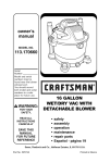
1
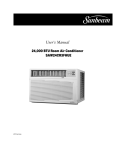
AC 12 10 8 6 MAN final
3/2/05
12:55 PM
Page 1
SLIDER CASEMENT ROOM AIR CONDITIONER
Use and Care Manual
CORREDIZO MARCO DE AIRE ACONDICIONADO PARA HABITACIONES
Manual de Uso y Mantenimiento
Thank you for purchasing an Admiral® room air conditioner. Please read this “Use and Care Manual” carefully
before installing and using this appliance. Keep this manual for future reference.
Muchase gracias por comprar un aire acondicionado Admiral®. Lea atentamente el “Manual de Uso y
Mantenimiento” antes de instalar y utilizar este producto. Conserve este manual para consultarlo en el futuro.
For Service Call 1 877 465 3566
Para obtener servicio técnico, llame al 1 877 465 3566
AC 12 10 8 6 MAN final
3/2/05
12:55 PM
Page 2
AC 12 10 8 6 MAN final
3/2/05
12:55 PM
Page 3
TABLE OF CONTENTS
Page
Introduction . . . . . . . . . . . . . . . . . . . . . . . . . . . . . . . . . . . . . . . . . . . . . . . . . . 2
Parts Identification . . . . . . . . . . . . . . . . . . . . . . . . . . . . . . . . . . . . . . . . . . . . . 2
Air Conditioner Safety . . . . . . . . . . . . . . . . . . . . . . . . . . . . . . . . . . . . . . . . . 3-4
Electrical Specifications . . . . . . . . . . . . . . . . . . . . . . . . . . . . . . . . . . . . . . . . .5
Tips Before Installation . . . . . . . . . . . . . . . . . . . . . . . . . . . . . . . . . . . . . . . . . 6
Installation Instructions . . . . . . . . . . . . . . . . . . . . . . . . . . . . . . . . . . . . . . . 7-8
Operating Instructions . . . . . . . . . . . . . . . . . . . . . . . . . . . . . . . . . . . . . . . 9-11
Care and Maintenance . . . . . . . . . . . . . . . . . . . . . . . . . . . . . . . . . . . . . . . . . 12
Troubleshooting Guide . . . . . . . . . . . . . . . . . . . . . . . . . . . . . . . . . . . . . . . . . 13
Warranty . . . . . . . . . . . . . . . . . . . . . . . . . . . . . . . . . . . . . . . . . . . . . . . . . . . 14
I´NDICE
Page
Introducción . . . . . . . . . . . . . . . . . . . . . . . . . . . . . . . . . . . . . . . . . . . . . . . . . 15
Identificación de las Piezas . . . . . . . . . . . . . . . . . . . . . . . . . . . . . . . . . . . . . 15
Especificaciones Eléctricas . . . . . . . . . . . . . . . . . . . . . . . . . . . . . . . . . . . . . 16
Consejos Antes dela Instalación . . . . . . . . . . . . . . . . . . . . . . . . . . . . . . . . . . 17
Instrucciones de Instalación . . . . . . . . . . . . . . . . . . . . . . . . . . . . . . . . . . 18-19
Instrucciones de Operación . . . . . . . . . . . . . . . . . . . . . . . . . . . . . . . . . . 20-22
Cuidado y Mantenimiento . . . . . . . . . . . . . . . . . . . . . . . . . . . . . . . . . . . . . . . 23
Guía para la Solución de Problemas . . . . . . . . . . . . . . . . . . . . . . . . . . . . . . . 24
Garantía . . . . . . . . . . . . . . . . . . . . . . . . . . . . . . . . . . . . . . . . . . . . . . . . . . . . 25
1
AC 12 10 8 6 MAN final
3/2/05
12:55 PM
Page 4
INTRODUCTION
Thank you for choosing this room air conditioner to cool your home. This USE AND CARE MANUAL
provides information necessary for the proper care and maintenance of your new room air conditioner.
If properly maintained, your air conditioner will give you many years of trouble free operation. To avoid
installation difficulties, read instructions completely before starting. This manual contains information for the
installation and operation of your room air conditioner.
Part Identification
➤PART
IDENTIFICATION
Fresh Air Lever
Control Panel
Horizontal Air Vane
Cabinet
Remote Control
Interior Air Outlet
FAN
SPEED
Closed
Open
Air Exchanger
TIMER
F
HR
Vertical Air
Vane
ON/OFF
ON/
MODE
Air Filter(Inside)
Exterior
Air Inlet
Interior Air
Inlet Grille
Power
Timer
Mode
Power Saver
Auto
Mid
Fan Speed
High
Low
_
+
Temp/Time
Front Panel
Control Panel
FAN
SPEED
Open
Closed
ON/OFF
F
HR
MODE
TIMER
Air Exchanger
Note:
The figures in this manual are based on the external view of a standard model.
Consequently, the shape may differ from that of the air conditioner you have selected.
2
AC 12 10 8 6 MAN final
3/2/05
12:55 PM
Page 5
AIR CONDITIONER SAFETY
Your safety and the safety of others are very important.
We have provided many important safety messages in this manual and on your appliance. Always read and obey
all safety messages.
This is the SAFETY ALERT SYMBOL.
This symbol alerts you to potential hazards that can kill or hurt you and others.
All safety messages will follow the safety alert symbol and either the word “DANGER” or
“WARNING.” These words mean:
You can be killed or seriously inured if you don’t
immediately follow instructions.
You can be killed or seriously inured if you
don’t follow instructions.
All safety messages will tell you what the potential hazard is, tell you how to reduce the chance of injury, and tell
you what can happen if the instructions are not followed.
IMPORTANT SAFETY INSTRUCTIONS
WARNING: To reduce the risk of fire, electrical shock, or
injury when using your air conditioner, follow these basic
precautions:
• Plug into a grounded 3-prong outlet.
• Do not use an extension cord.
• Do not remove ground prong.
• Unplug air conditioning before
servicing.
• Do not use an adapter.
• Use two or more people to
move and install air conditioner.
— SAVE
THESE
INSTRUCTIONS —
3
AC 12 10 8 6 MAN final
3/2/05
12:55 PM
Page 6
INSTALLATION REQUIREMENTS
• The portable air conditioner should be connected
to a 115 V, 60 Hz, 15- or 20-amp fused 3-prong
grounded outlet.
• The use of a time-delay fuse or time-delay circuit
breaker is recommended.
Power Supply Cord
NOTE: Your unit’s device may differ from the one shown.
• All wiring must comply with local and national
electrical codes and be installed by a qualified
electrician. If you have any questions, contact
a qualified electrician.
Electrical Requirements
A Reset Button
B Test Button
This room air conditioner is equipped with a power supply cord required
by UL. This power supply cord contains state-of-the-art electronics that
sense leakage current. If the cord is crushed, the electronics detect leakage
current and power will be disconnected in a fraction of a second.
To test your power supply cord:
1.
2.
3.
4.
ELECTRIC SHOCK HAZARD
• Plug into a grounded 3-prong outlet.
• Do not remove ground prong.
• Do not use an adapter.
• Do not use an extension cord.
• Failure to follow these instructions can
result in death, fire, or electrical shock.
Plug power supply cord into a grounded 3-prong outlet.
Press RESET.
Press TEST (listen for click; Reset button will trip and pop out).
Press and release RESET (listen for click; Reset button will latch
and remain in).The power supply cord is ready for operation.
NOTES:
• The Reset button must be pushed in for proper operation.
• The power supply cord must be replaced if it fails to trip when the
test button is pressed or fails to rest.
• Do not use the power supply cord as as an off/on switch. The
power supply cord is designed as a protective device.
• A damaged power supply cord must be replaced with a new power
supply cord obtained from the product manufacturer and must not
be repaired.
• The power supply cord contains no use serviceable parts. Opening
the tamper-resistant case voids all warranty and performance claims.
INSTALLATION INSTRUCTIONS
Unpack the Air Conditioner
EXCESSIVE WEIGHT HAZARD
Use two or more people to move and
install air conditioner.
Failure to do so can result in back or
other injury.
Remove packaging materials
• Remove and properly dispose of packaging materials.
Remove tape and glue residue from surfaces before
turning on the air conditioner. Rub a small amount
of liquid dish soap over the adhesive with your fingers.
Wipe with warm water and dry.
• Do not use sharp instruments, rubbing alcohol,
flammable fluids, or abrasive cleaners to remove
tape or glue. These products can damage the
surface of your air conditioner.
• Handle air conditioner with care.
4
AC 12 10 8 6 MAN final
3/2/05
12:55 PM
Page 7
ELECTRICAL SPECIFICATIONS
1. All wiring must comply with local and national
electrical codes and must be installed by a
licensed electrician. Once you have any questions
regarding the following instructions, contact a
licensed electrician.
Electric Shock Hazard
If the air conditioner has a serial plate rating
of 115 volts and up to and including 7.5 amps
the unit maybe on a fuse or circuit breaker
with other devices. However, the maximum
amps of all devices on that fuse or circuit
breaker can not exceed the amps of the fuse
of circuit breaker.
2. Check available power supply and resolve any
wiring problems BEFORE installing and operating
this unit.
If the air conditioner has a serial plate rating
of 115 volts and greater than 7.5 amps it
must have its own fuse or circuit breaker,
and no other device or unit should be
operated on the fuse or circuit breaker.
3. For your safety and protection. This unit is
grounded through the power cord when
plugged into a matching wall outlet. If you are
not sure whether your wall outlet is properly
grounded, please consult a licensed
electrician.
To avoid the possibility of personal injury,
disconnect power to the unit before installing
or servicing.
Receptacle and Fuse Types
4. The wall outlet(3-pin) must match the plug
(3-pin) on the service cord supplied with the unit.
DO NOT use plug adapters or extension cord.
See (Table 1) for receptacle and fuse information.
Rated Volts
125
15
AMPS
Wall Outlet
5. The rating plate on the unit contains electrical
and other technical data. The rating plate is located
on the right side of the unit.
Fuse Size
15
Time Delay Fuse
(or circuit breaker)
Plug type
Table 1
5
AC 12 10 8 6 MAN final
3/2/05
12:55 PM
Page 8
TIPS BEFORE INSTALLATION
NOTE:
Save the shipping carton and packing
materials for future storage or transport of the unit.
Please check the contents of hardware kit against
the corresponding model check list, prior to
installation of the unit. See lists below.(Fig.A)
Your Room Air Conditioner unit is designed to
be highly efficient and save energy. Follow these
recommendations for greater efficiency.
1. Select the thermostat setting that suits your
comfort needs and leave the thermostat at
that chosen setting.
Fig. 1A Installation
Fig. A Installation
Hardware Model
Hardware
463AAC008BA
2. The filter is very efficient in removing airborne
particles. Keep air filter clean. Normally, filter
should be cleaned once a month. More
frequent cleaning may be necessary depending
on outdoor and indoor air quality.
3/8"Screws (4)
Nuts(2)
1"Screws (2)
Washers(2)
7/16" Screws(2)
3. Use drapes, curtains, or shades to keep
direct sunlight from heating your room, but
DO NOT obstruct the air conditioner. Allow air to
circulate around the unit without obstructions.
Support
platform(1)
Speed clips(2)
4. Start your air conditioner before outdoor
air becomes hot and uncomfortable. This
avoids an initial period of discomfort while
the unit is cooling off the room.
Support angles (1)
5. When outdoor temperature is cool
enough, use HIGH or LOW FAN
only. This circulates indoor air, providing
some cooling comfort, and utilizes less
electricity than when operating on a
cooling setting.
Top channel(1)
End Cap &
Leveling Leg (1)
Filler panel(1)
Side
channels(2)
Factory installed
Sliders(2)
Factory installed
Shorter
seal (1)
Bottom bar(1)
Factory installed
Seals (2)
Top retainer (1)
!
CAUTION
!
Side seals (2)
Foam (1)
Factory installed
To avoid installation/operating difficulties,
read the instructions thoroughly.
NOTE: Surplus screw(s) for spare use.
Your Room Air Conditioner was designed for
easy installation in a vertical (slider type) windows.
NOTE: This unit is NOT designed for single
or double-hung windows.
Tools Needed for Window Installation
Screw drivers: Both Philips and flat head
Power drill:
1/8 inch diameter drill bit
Pencil
Measuring tape
Scissors
Carpenters level
6
AC 12 10 8 6 MAN final
3/2/05
12:55 PM
Page 9
INSTALLATION INSTRUCTIONS
Sliding Window Installation
A
7/16"Screws
Support
platform
Support angle
Leveling bolt
1.Choose the installation site. It is imperative that the window
frame assembly and the side of the structure are adequate to
support the weight of the unit. Reinforce if necessary.
2.Slide open one window sash to install support platform.
3.Loosely attach support angle to bottom of support platform
using two 7/16" screws, washers and nuts. (See fig. A)
4.Place support platform against lower window track and
firmly against vertical edge of window frame.
5.Attach support platform to window sill using two 1 "
self-tapping screws. To overcome interference of support the
Platform with window track or storm window, securely attach
a 2 " wide shim strip to the window sill. The strip should be as
long as the width of the support platform and flush with the back
edge of the sill. The thickness of the strip should be controlled
by the amount of interference.(See fig. B)
6.Pull support angle against outside of structure. Tighten two
7/16 " screws on top of the support platform.
7.Adjust leveling bolt to position support angle in a level
plane. This will allow for the proper angle. Tighten leveling
bolt locknut.
Important: Unit must be level or tilted back slightly to
facilitate proper condensate disposal.
B
Two 1" long self-tapping screws
Support platform
assembly
8.Cut two pieces of adhesive seal to height of window
opening. Remove backing and apply tovertical inside
edges of window frame and sliding sash that will rest
against unit.(See fig. C)
9.Slide unit onto support platform. Be sure unit side
channel butts against vertical edge of window frame.
Note: If unit side channel does not fit securely,
remove unit and readjust leveling bolt.
Lower window
track
C
Seal
Top retainer
Filler panel
Sliders
Shorter seal
Caution: Do not drill a hole in the bottom pan. The unit
is designed to operate with approximately 1/2" of
water in the bottom pan.
10.Drill two 1/8" holes through window channel frame
in alignment with existing holes in bottom bar. Install
two 3/8" long self-tapping screws through these holes.
If the window channel frame is not tall enough to use
existing holes, drill new holes off to the side of the
existing holes to attach the unit bottom bar to the
support platform.The unit should be firmly anchored to the
window channel frame or support platform.(See fig. D)
11.Slide inside window sash closed. Be sure vertical edge
of inside window sash is pressed firmly against side of unit
cabinet. Cut remaining seal to width of window opening.
Remove backing and apply to top inside edge of window
frame.(See fig. C)
The above installations are intended to be permanent,
and when installed in apartment or rental properties,
permission to make the above modifications should be
obtained from owners or landlords of buildings prior
to installation of unit.
7
AC 12 10 8 6 MAN final
3/2/05
12:55 PM
Page 10
INSTALLATION INSTRUCTIONS
Installation
12.Install speed clips on top and bottom inside edge
of window to provide locking. (See fig. E)
13.Using supplied foam, cut to proper length, insert
between inside window sash and outside window.(See fig. E)
14.Place top retainer on top edge of filter panel, then place
the bottom edge of filler panel into groove of bottom retainer
(mounted on unit). Filler panel may be trimmed with knife or
scissors to fit window height.(See fig. C)
15.Slide sliders upward making sure filler panel aligns in
sliders.
16.With sliders up against top retainer, drill 1/8" hole
through window frame in alignment with existing hole in
slider. Install 3/8 " long self-threading screw in hole.
Repeat for other slider.
17.Check all seals and plug all air leaks around unit. Use
supplied sealant to fill any minor openings.
D
Support platform
Drilled holes
Central line
Bottom bar(on the
bottom of Cabinet)
4.9
Window channel frame
4.9
Casement Window Installation
This air conditioner is designed to fit into most casement type
windows. As shipped from factory, unit will fit into a minimum
window opening 151/2" wide and 22"high. The preferred
method of installation is through a closed or stationary window.
Installation in an open window frame is also possible where
open window can be secured to outside of building or removed
completely.
3/8" long screws
Drilled holes
E
3/8" long screws
Speed clips
1.Closed or stationary window: Install unit in stationary sash to
avoid crank handles or window latches. If unit is to be installed
in or next to a movable sash, it may be necessary to remove catch,
handle or both. Remove crank handle and secure window in closed
position. Remove glass panes and separating strips to a height
sufficient to mount unit.
2.Open window frame: Remove crank mechanism and catch handles.
Fold window sash back against exterior wall of building and secure,
or remove completely where possible.
3. A filler panel will be required at side of unit when installed in
windows having width greater than 151/2". Filler panel should be
made from 3/4 " thick wood securely anchored to one side of
opening so that 15 1/2" wide opening is provided. Filler panel
should run full length of window. Paint to suit.
4. Install unit in same manner as described for sliding windows.
Channel
Installation in wood sliding or wood casement windows
1.For wood frame casement windows, it is necessary to construct a
frame, using at least 1 " thick wood with a 15 1/2" wide opening.
2.Paint frame and fasten it securely, sealing it into window opening.
3.Install unit into frame following procedures for metal sliding and
casement windows.
Foam
These installations are also typical, and since styles and sizes of
casement windows vary widely, it is advisable to have unit installed
by someone skilled in this type of installation. The dealer selling
these units can recommend or supply qualified people to install
your new unit.
Caution: Do not block air circulation to outside
louvers of cabinet.
8
AC 12 10 8 6 MAN final
3/2/05
12:55 PM
Page 11
OPERATING INSTRUCTIONS
4.CONTROL PANEL(Only for electronic models)
Caution: If air conditioner is shut off, wait a minimum of three minutes before restarting
Control Functions
Air Exchanger: Circulates fresh air and helps remove stale air when in the open position. Maximum air circulation and
cooling occur when in the closed position.
ON/OFF button
The air conditioner will be started when it is energized or will be stopped when it is in operation, if you press
this button.
MODE button
Each time MODE button is pressed, the operation mode is changed in sequence:
COOLING FAN ONLY ENERGY SAVING COOLING
NOTE: After setting the mode, allow 3 minutes before switching to another mode.
FAN SPEED button
Used to select fan speed in sequence auto, low, medium and high.
TIMER button
button
TIMER
Used to
to set
set or
or cancel
canceltimer
timeroperation.
operation.
Used
When the unit
unit is
is in
in operation,
operation,you
youcan
canset
setOFF
OFF TIMER.
TIMER. When
When the unit
unit is
is off,
off, you
you can
canset
setON
ONTIMER.
TIMER.
When
Timer setting
setting range
range is
is 00 to
to24
24hours.
hours.
Timer
If the OFF TIMER is set, the timer LED displays the remaining time to turn off the unit for only 12 seconds,
then LED shifts to display set temperature.
If you press TIMER button within the 12 seconds, OFF TIMER will be canceled.
If the ON TIMER is set, the timer LED displays the remaining time to turn on the unit.
If you want to cancel ON TIMER, press TIMER button.
Button
Used to set
set room
room temperature
temperature in
in COOLING
COOLING mode
mode or
or used
used to
to set
set time
timeininTIMER
TIMER mode.
mode.
two keys
keys are
are pressed
pressed at
at the
the same
same time,the
time, thetemperature
temperatureLED
LEDdisplay
displaywill
willalternate
alternatebetween
between °C
and .°F.
If the two
and
NOTE:
Temperature
setting
range
is from 19°C
NOTE:
Temperature
setting
range
is from19
(66 (66°F)
) to 31to 31°C
(88 (88°F).
).
Indication symbols of LED on control panel:
Auto fan speed
Cooling
Low fan speed
Fan only
Medium fan speed
Timer
High fan speed
Energy-saving
F
HR
Display set temp
Display set timer
The above LED lights are shown when the relevant mode is in use.
9
AC 12 10 8 6 MAN final
3/2/05
12:55 PM
Page 12
OPERATING INSTRUCTIONS
➤REMOTE
CONTROL
Remote control
1 Power BUTTON
1
2
7
Power
Timer
Mode
Power Saver
Auto
4
Mid
Fan Speed
High
3
The appliance will be started when it is
energized or will be stopped when it is
in operation, if you press this button.
8
9
2
5
3
6
Low
_
Mode BUTTON
Used to select the operation mode.
4
+
Temp/Time
BUTTONS
Used to set room temperature in COOLING
mode or used to set time in Timer mode.
High BUTTON
Used to select the high fan speed mode.
5
Mid BUTTON
Used to select the mid fan speed mode.
6
Low BUTTON
Used to select the low fan speed mode.
7
Auto BUTTON
Used to select the auto fan speed mode.
8 Timer BUTTON
Used to set or cancel timer operation.
9
Power Saver BUTTON
Used to select the Energy-saving mode.
!
• When changing modes during operation, sometimes the unit does not always
• respond at once. Wait three (3) minutes.
• Wait three (3) minutes before restarting the appliance.
10
AC 12 10 8 6 MAN final
3/2/05
12:55 PM
Page 13
OPERATING INSTRUCTIONS
➤REMOTE CONTROL
Remote control
How to Insert the Batteries
Remove the battery cover according to the arrow direction.
Insert new batteries making sure that the (+) and (-) of
battery are matched correctly.
Reattach the cover by sliding it back into position.
Note:
Use 2 LR6 AA(1.5volt) batteries. Do not use rechargeable batteries.
Replace batteries with new ones of the same type when the display
becomes dim.
If the replacement is done within 1 minute, the remote control
will keep original presetting. (This function only for LCD remote
control)
Signal receptor
How to Use
To operate the room air conditioner, aim
the remote control to the signal receptor.
The remote control will operate the air
conditioner at a distance of up to 23 feet
when pointing at signal receptor of indoor
unit.
FAN
SPEED
Closed
Open
Air Exchanger
11
TIMER
F
HR
ON/OFF
MODE
AC 12 10 8 6 MAN final
3/2/05
12:55 PM
Page 14
CARE AND MAINTENANCE
When servicing the air conditioner, be sure to turn the mode switch to the "OFF" position and disconnect the
power cord from the electrical outlet.
1. DOT NOT use gasoline, benzine, thinner or other chemicals on the air conditioner as these substances
may cause damage to the paint finish and deformation of plastic parts.
2. Never attempt to pour water directly on the front of the unit as this will cause deterioration of the electrical
insulation.
Cleaning the Air Filter
NOTE: Failure to keep the air filter clean will result in poor air circulation. DO NOT operate without a filter.
This can render the unit inoperative.
Proper use and care of your air conditioner will help ensure longer life of the unit. It is recommended to annually
inspect and clean the coils and condensate water passages. Expense of annual inspection is the consumers
responsibilities.
When the air filter inlet grill and cabinet are dirty, wipe with lukewarm water (below 104 F/ 40 C). Use of mild
detergent is recommended.
O
O
Directing airflow
Air conditioner is engineered with adjustable louvers to direct discharge airflow. Louvers are manually adjusted by
moving levers in direction of desired airflow.
Cleaning Air Filter
When the air conditioner is operating, indoor air is filtered and refiltered continuously trapping airborne dirt and dust in
the washable filter. Therefore, the filter should be inspected and cleaned weekly.
1.Turn the unit off.
2.Grasp both sides near top of inlet grill and pull forward. Inlet grill will pivot forward to reveal air filter.
3.Remove air filter from tabs.
4.Carefully wash air filter with a mild detergent and warm water. Rinse with clear water, squeeze dry and replace.
5.Replace inlet grill.
Air Filter Removal:
The air filter on the above model is located behind the air intake front grill.
To remove the air filter, grasp the filter handle(tab)
located on the top side of the air inlet grille and slide the air filter to the top.
(See the right fig.)
To reinstall the air filter, reverse the above procedure.
End-of-Season Care
1. Operate the fan alone for half a day to dry out the inside of the unit.
2. Turn off power and remove plug from wall socket.
3. Clean filter.
4. Store in a dry location.
12
AC 12 10 8 6 MAN final
3/2/05
12:55 PM
Page 15
TROUBLESHOOTING GUIDE
Frequently, a problem is minor and a service call may not be necessary, use this troubleshooting guide for a
possible solution.
PROBLEM
Air conditioner will
not operate
POSSIBLE CAUSE
No power to the unit.
SUGGESTED SOLUTION
Check connection of power cord to
power source.
Check fuse or circuit breaker.
Set MODE knob to position other
than "OFF".
Inefficient or no cooling
Dirty air filter.
Clean or replace air filter.
Inappropriate capacity
for application.
Check with dealer to determine proper unit
capacity for application.
Blocked air flow.
Remove obstruction from grill or
outdoor louvers.
Power interruption, settings
change too quickly, or
compressor overload tripped.
Let fan run to restart compressor
(in approximately 10 minutes).
Noisy unit
Loose parts.
Inadequate support.
Tighten loose parts.
Provide additional support to unit.
Odors
Formation of mold, mildew, or
algae on wet surfaces.
Remove drain plug and drain base pan.
Replace drain plug.
Clean unit thoroughly.
Water dripping outside
Condensation run-off is normal
during hot and humid weather
Add flexible tubing to redirect water flow.
Water dripping inside
. is not properly angled to
Unit
allow water to drain outside.
Unit must be installed on an angle for proper
condensation run-off. Check the unit and
make adjustments.
Ice or frost build-up
Low outside temperature.
When outdoor temperature is approximately
65 F or below, frost may form when unit is in
cooling mode. Switch unit to FAN (only)
operation until frost melts.
Unit air filter is dirty.
Remove and clean filter.
NOTE:
If circuit breaker is tripped repeatedly, or fuse is blown more than once, contact a licensed technician.
13
AC 12 10 8 6 MAN final
3/2/05
12:55 PM
Page 16
WARRANTY
5 YEAR FULL WARRANTY
This product is warranted for 5 years from the date of original purchase. Any part
which fails in materials or workmanship will be replaced within the warranty period.
This warranty covers in home service. A copy of your proof of purchase, with date of
purchase and product name included, is required to arrange this service repair.
For the name and location of an authorized service provider nearest you, please
CALL 1-877-465-3566. Please reference product name, brand name, and model
number when you call.
This warranty does not apply if the damage occurs because of accident, improper
handling or operation, shipping damage, abuse, misuse, unauthorized repairs
made or attempted, or the use of the product for commercial use, or any other use
for which it was not intended.
ALL WARRANTIES, EXPRESSED OR IMPLIED, LAST FOR 5 YEARS FROM THE
DATE OF ORIGINAL PURCHASE.
THIS WARRANTY DOES NOT COVER
LIABILITY FOR INCIDENTAL OR CONSEQUENTIAL DAMAGES FOR ANY
CAUSE WHATSOEVER.
This warranty is extended to the original owner and any succeeding owner for
products purchased for home use within the USA. Some states do not allow the
exclusion or limitation of incidental or consequential damages. This warranty
gives you specific rights, and you may also have other rights which may vary from
state to state. To know what your legal rights are, consult your local or state
consumer affairs office or your state's Attorney General.
14
AC 12 10 8 6 MAN final
3/2/05
12:55 PM
Page 17
Introducción
TABLE OF CONTENTS
Gracias por elegir este aire acondicionado para enfriar su hogar. Este MANUAL DE USO Y MANTENIMIENTO
proporciona la informaci n necesaria para cuidar y mantener en forma adecuada su nuevo aire acondicionado.
Funcionar sin problemas durante muchos anos si le brinda el mantenimiento apropiado. Para evitar
problemas al instalarlo, lea completamente las instrucciones antes de comenzar. Este manual contiene
informaci n acerca de la instalaci n y el funcionamiento del aire acondicionado para habitaciones.
Identificaci n de las Piezas
➤Identificación
de las Piezas
Modelo de Remoto controlador
Palanca de Aire Fresco
Panel de Control
Aleta de Aire Horizontal
Gabinete
Entrada de
Aire Interior
Aleta de
Aire Vertical
FAN
SPEED
Filtro de Aire
(en el interior)
Closed
Open
Air Exchanger
TIMER
F
HR
Control Remoto
ON/OFF
MODE
Entrada de
Aire Exterior
Rejilla de
Entrada de
Aire Interior
Power
Timer
Mode
Power Saver
Auto
Mid
Fan Speed
High
Panel Frontal
Low
_
+
Temp/Time
Panel de Control
FAN
SPEED
Open
Closed
ON/OFF
F
HR
MODE
TIMER
Air Exchanger
Nota:
Las im genes de este manual est n basadas en la vista externa de un modelo est ndar.
En consecuencia, es probable que la forma sea diferente a la del aire acondicionado
que usted seleccion .
15
AC 12 10 8 6 MAN final
3/2/05
12:55 PM
Page 18
TABLE OF CONTENTS
Especificaciones
eléctricas
1. Todos los cables deben cumplir con los c digos
el ctricos locales y nacionales y los debe instalar
un electricista licenciado. Si tiene preguntas
relacionadas con las siguientes instrucciones,
comun quese con un electricista licenciado.
Peligro de Descarga El ctrica
Si el r tulo del aire acondicionado indica 115
voltios y hasta 7.5 amperios, la unidad se
puede conectar a un cortacircuito o fusible
utilizado por otros dispositivos. No obstante,
la suma de los amperios m ximos de todos
los dispositivos conectados a dicho
cortacircuito o fusible no deben exceder los
amperios del mismo.
2. Verifique el suministro de energ a disponible y
resuelva cualquier problema con los cables ANTES
de instalar y hacer funcionar esta unidad.
3. Para su seguridad y protecci n, esta unidad est
conectada a tierra a trav s del cable de alimentaci n
cuando se lo enchufa a un tomacorriente de pared
provisto de conexi n a tierra. Si no est seguro de
que el tomacorriente de pared cuenta con la
conexi n a tierra apropiada, consulte con un
electricista licenciado.
4. El tomacorriente de pared (de 3 clavijas) debe
coincidir con el enchufe (de 3 clavijas) del cable de
alimentaci n suministrado con la unidad. NO utilice
adaptadores de enchufe ni cables de extensi n.
Consulte la Tabla 1 para obtener informaci n acerca
de recept culos y fusibles.
Si el r tulo del aire acondicionado indica 115
voltios y m s de 7.5 amperios, debe tener su
propio fusible o cortacircuito y no se deber
conectar ning n otro dispositivo o unidad a dicho
fusible o cortacircuito.
Para evitar lesiones f sicas, desconecte el
suministro de energ a de la unidad
antes de instalarla o repararla.
Tipos de Recept culos y Fusibles
Capacidad de Voltios
125
15
Amperios
Tomacorriente de Pared
5. El r tulo de la unidad contiene datos el ctricos y
t cnicos. Dicho r tulo se encuentra en el lado
derecho de la unidad.
15
Tamano del Fusible
Fusible con Retardo
(o Cortacircuito)
Tipo de enchufe
Tabla 1
16
AC 12 10 8 6 MAN final
3/2/05
12:55 PM
Page 19
TABLE OF antes
Consejos
CONTENTS
de la instalación
NOTA: conserve la caja de la unidad y los materiales
de empaque para almacenarla o transportarla en el
futuro. Antes de instalar la unidad compare el
contenido del juego de herrajes con la lista de control
del modelo correspondiente. Consulte las siguientes
listas (Fig. A).
Su unidad de Aire Acondicionado para Habitaciones
se ha disenado para lograr un alto rendimiento y
ahorrar energ a el ctrica. Siga las siguientes
sugerencias para lograr un mayor rendimiento.
1. Ajuste el termostato a un nivel que le resulte
agradable y d jelo en el nivel seleccionado.
de Instalaci
n
Fig. 1A Fig.
Installation
A Herrajes
Hardware
Model 463AAC008BA
2. El filtro de aire es muy eficiente a la hora de eliminar
part culas que se desplazan por el aire. Mantenga
limpio el filtro de aire. Por lo general, el filtro deber
limpiarse una vez al mes. Es probable que sea
necesario limpiarlo con m s frecuencia dependiendo
de la calidad del aire exterior o interior.
Tornillos de 3/8" (4)
Tuercas (2)
Tornillos de 1" (2)
Junta de Culata (2)
Tornillos de 7/16" (2)
Plataforma
de montaje (1)
3. Puede utilizar tapices, cortinas o pantallas para
evitar que la luz directa del sol caliente su habitaci n,
pero NO obstruya el aire acondicionado. Permita
que el aire circule alrededor de la unidad sin
obstrucciones.
Trabas de
sujeci n (2)
Soporte
en ngulo(1)
4. Encienda el aire acondicionado antes de que la
temperatura exterior sea demasiado elevada y
desagradable. De esta manera evitar sufrir calor
mientras la unidad enfr a la habitaci n.
Tapa Trasera y Patas
de Nivelaci n ( )
Panel Relleno(1)
Canal lado (2)
Instalado en la f brica
Canal Superior (1)
Instalado en la f brica
Zanja deslizada (2)
5. Cuando la temperatura exterior es lo suficientemente
fresca, utilice s lo HIGH FAN (ventilador al m ximo) o
LOW FAN (ventilador al m nimo). Esto hace que el aire
interior circule a una temperatura agradable y consume
menos energ a el ctrica que si hiciera funcionar la
unidad como enfriador de aire.
Bottom bar (1)
Instalado en la f brica
Sujetador superior (1)
Espuma (1)
!
PRECAUCI N !
Para evitar problemas durante la instalaci n o el
funcionamiento de la unidad, lea completamente
las instrucciones.
El Aire Acondicionado para Habitaciones se ha
disenado de modo tal que resulte f cil su instalaci n
en ventanas verticales (de tipo deslizante). NOTA:
esta unidad NO se ha disenado para ventanas
armadas sencillas o dobles.
Sello m s
corta (1)
Sello (2)
Sello lado (2)
Instalado en la f brica
Nota: Tornillo Excedente Para d Uso de Reserva.
Herramientas Necesarias para la Instalaci n en Ventana:
Destornilladores: Philips y de cabeza plana
Taladro el ctrico: broca de 1/8 pulgada de di metro
L piz
Cinta m trica
Tijeras
Nivel de carpintero
17
AC 12 10 8 6 MAN final
3/2/05
12:55 PM
Page 20
TABLE OF CONTENTS
Instrucciones
de Instalación
Instalaci n en Ventanas Deslizantes de Metal
A
Tornillos
de 7/16"
Plataforma
de montaje
Soporte
en ngulo
Perno de
nivelaci n
B
Dos tornillos autorroscantes
de 1" de largo
Plataforma de montaje
ensamblada
Gu a inferior
de la ventana
C
Sello
Sujetador superior
Panel de
relleno
Correderas
Sello m s corta
La instalaci n mencionada debe ser permanente y
si se realiza en un apartamento o en una propiedad
de alquiler, antes de instalar la unidad deber
solicitar permiso a los propietarios o encargados
del edificio para realizar las modificaciones
mencionadas.
1. Escoja el lugar de instalaci n. Es imprescindible que el montaje
en el marco de la ventana y el costado de la estructura est n
ensamblados correctamente de modo que puedan sostener el
peso de la unidad. Refu rcelos si es necesario.
2. Deslice una hoja de la ventana para abrirla e instalar la
plataforma de montaje.
3. Sujete el soporte en ngulo a la parte inferior de la plataforma
de montaje con dos tornillos de 7/16" de largo, junta de culata y
tuercas, pero no los apriete (vea la Fig. A).
4. Coloque la plataforma de montaje contra la gu a inferior de la
ventana y el borde vertical del marco de la ventana.
5. Suj tela al umbral de la ventana con dos tornillos autorroscantes
de 1" de largo. Para corregir la interferencia de la plataforma de
montaje con la gu a de la ventana o la ventana resistente a
huracanes, sujete firmemente un list n de compensaci n de 2" de
ancho al umbral de la ventana. El list n deber tener un largo
igual al ancho de la plataforma de montaje y estar alineado con
el borde posterior del umbral. El grosor del list n deber depender
de la cantidad de interferencia (vea la Fig. B).
6. Jale el soporte en ngulo hacia la parte exterior de la estructura.
Apriete dos tornillos de 7/16" de largo en la parte superior de la
plataforma de montaje.
7. Ajuste el perno de nivelaci n de modo que el soporte en ngulo
quede nivelado. Esto permitir que quede bien apoyado. Apriete
la tuerca del perno de nivelaci n.
Importante: la unidad debe estar a nivel o levemente inclinada
hacia atr s para permitir la descarga adecuada de la
condensaci n de la humedad del aire.
Precauci n: no perfore la bandeja inferior. La unidad tiene un
diseno que le permite funcionar con aproximadamente 1/2" de
agua en la bandeja inferior.
8. Corte dos pedazos de sello igualesa la altura de la ventana.
Qu teles el revestimiento y apl quelas a los bordes
interiores verticales del marco de la ventana y a la hoja de la
ventana deslizante que quedar apoyada contra la unidad
(vea la Fig. C).
9. Coloque la unidad sobre la plataforma de montaje. Aseg rese
de que los canales laterales de la unidad hagan tope con el borde
vertical del marco de la ventana.
Nota: si el canal lateral de la unidad no queda firme,
extr igala y vuelva a ajustar al perno de nivelaci n.
10. Haga dos orificios de 1/8" en el canal del marco de la ventana
alineados con los orificios de la barra inferior. En estos orificios
coloque dos tornillos autorroscantes de 3/8" de largo. Si el canal
del marco de la ventana no es lo suficientemente alto como para
utilizar los orificios existentes, haga orificios nuevos al lado de los
existentes para sujetar la barra inferior de la unidad a la plataforma
de montaje. La unidad deber quedar firmemente asegurada al
canal del marco de la ventana o a la plataforma de montaje
(vea la Fig. D).
11. Deslice la hoja interna de la ventana para cerrarla. Aseg rese
de que el borde vertical de la hoja interna de la ventana haya
quedado firmemente presionado contra el costado del gabinete de
la unidad. Corte la sello restante igual alancho de la abertura de
la ventana. Qu tele el revestimiento y apl quela al borde superior
interno del marco de la ventana (vea la Fig. C).
18
AC 12 10 8 6 MAN final
3/2/05
12:55 PM
Page 21
TABLE OF CONTENTS
Instrucciones
de Instalación
Instalaci n
D
Plataforma de montaje
Orificios
perforados
Centro
Barra inferior
(en el fondo de gabinete)
4.9
4.9
Canal del marco
de la ventana
Orificios perforados
Tornillos de
3/8" de largo
E
Trabas de sujeci n
Canal
Espuma
Precauci n: no obstruya la circulaci n de aire
por las persianas externas del gabinete.
12. Instale las trabas de sujeci n en los bordes superior e nferior
del interior de la ventana para asegurarla. (Vea la Fig. E)
13. Corte la espuma suministrada del largo necesario e
ins rtela entre la hoja de ventana interior y el exterior de
la ventana (Vea la Fig. E).
14. Coloque el sujetador superior en el borde superior del
panel del filtro, luego coloque el borde inferior del panel de
relleno en la ranura inferior (montada en la unidad). El panel
de relleno se puede cortar con cuchillo o tijera para adaptarlo
a la altura de la ventana (Vea la Fig. C).
15. Deslice las correderas hacia arriba y aseg rese de que
el panel de relleno est alineado en las correderas.
16. Una vez que las correderas est n contra el sujetador
superior, haga un orificio de 1/8" en el marco de la ventana
alineado con el orificio existente en la corredera. Coloque un
tornillo autorroscante de 3/8" de largo en el orificio. Haga lo
mismo con la otra corredera.
17. Verifique todos los sellos y tape toda p rdida de aire
alrededor de la unidad. Utilice el sellador suministrado para
tapar todo hueco pequeno.
Instalaci n en Ventanas de Hoja Batiente de Metal
Este aire acondicionado tiene un diseno que facilita su colocaci n en la
mayor a de las ventanas de hoja batiente. Tal como se la env a de
f brica, la unidad puede colocarse en una abertura de ventana de
15 1/2" de ancho y 22" de alto como m nimo. Es preferible
instalarla en una ventana cerrada o estacionaria. Tambi n se puede
instalar en un marco de ventana abierta siempre que sta pueda
sujetarse al exterior del edificio o extraerse por completo.
1 .Ventana cerrada o estacionaria: Instale la unidad en una hoja de
ventana estacionaria para evitar manijas o cerrojos de ventana. Si la
unidad se instalar en una hoja de ventana m vil o junto a ella, es
posible que sea necesario extraer el pasador, la manija o ambos.
Quite la manivela y deje la ventana cerrada. Quite las hojas de vidrio
y los listones de separaci n de modo que quede suficiente altura
como para montar la unidad.
2. Abra el marco de la ventana, quite la manivela y los pasadores.
Pliegue la hoja de la ventana hacia atr s contra la pared externa del
edificio y aseg rela, o si es posible qu tela completamente.
3. Ser necesario colocar un panel de relleno al costado de la unidad
cuando se la instale en ventanas de un ancho superior a 15 1/2".
Dicho panel deber ser de madera, tener un espesor de 3/4 y estar
asegurado a un costado de la abertura de modo que quede una abertura
de 15 1/2" de ancho. El panel de relleno deber abarcar el largo total
de la ventana. P ntelo del color correspondiente.
4. Instale la unidad tal como se ha descrito en la secci n de Instalaci n
en Ventanas Deslizantes de Metal antes descrita.
Instalaci n en Ventanas de Madera (Deslizantes o de Hoja Batiente).
1. En ventanas de hoja batiente de madera es necesario construir un
marco de madera de por lo menos 1" de espesor con una abertura de
15 1/2" de ancho.
2. Pinte el marco y suj telo firmemente. S llelo a la abertura de la ventana.
3. Instale la unidad en el marco siguiendo los procedimientos para
ventanas de metal (deslizantes o de hoja batiente).
Estas instalaciones tambi n son comunes, y debido a que los estilos y
tamanos de las ventanas de hoja batiente son tan variados, le
recomendamos que busque a una persona calificada para realizar este
tipo de instalaci n. El representante que vende estas unidades puede
recomendar o proporcionar personal capacitado para instalarlas.
19
AC 12 10 8 6 MAN final
3/2/05
12:55 PM
Page 22
TABLE OF CONTENTS
Instrucciones
de Operación
Este aire acondicionado se puede operar f cilmente con los botones del panel de control as como
tambi n con el control remoto.
Precauci n: Espere tres minutos antes de volver a comenzar
Panel de Control
Funciones del Control
Intercambiador de Aire: cuando est abierto hace que circule el aire fresco y elimina el aire viciado. El m ximo
enfriamiento y circulaci n de aire se producen cuando est cerrado.
Bot n ON/OFF (Encendido/Apagado)
Si presiona este bot n, encender el aire acondicionado (o lo apagar si est en funcionamiento).
Bot n MODE (Modo)
Cada vez que se presiona el bot n MODE, el modo de operaci n cambia en estas secuencias:
COOLING (Enfriamiento) FAN ONLY (S lo ventilador) ENERGY SAVING (Ahorro de Energ a)
COOLING (Enfriamiento)
NOTA:
Despu sde
deseleccionar
seleccionar
nivel,espere
espere
3 minutos
antes
de pasar
a otro.
NOTA: Después
unun
niveol,
3 minutos
antes
de pasar
a otro.
Bot
n FAN
FAN SPEED
SPEED(Velocidad
(Velocidad
Ventilador)
Botón
deldel
Ventilador)
Se
utilizapara
paraseleccionar
seleccionar
velocidad
ventilador
en secuencia:
autombaja,
tica,media
baja, ymedia
Se utiliza
la la
velocidad
deldel
ventilador
ensecuencia:
automótica,
alta. y alta.
Bot n TIMER (Temporizador)
Se utiliza para programar o cancelar el funcionamiento del temporizador.
Cuando la unidad est en funcionamiento, puede seleccionar OFF TIMER (Apagar Temporizador).
Cuando la unidad est apagada, puede seleccionar ON TIMER (Encender Temporizador).
El rango de horas para programar el temporizador es de 0 a 24 horas.
Si selecciona OFF TIMER, la pantalla del temporizador indicar durante 12 se gundos
el tiempo restante para el apagado de la unidad y luego indicar la temperatura fijada.
Si presiona el bot n TIMER dentro de esos 12 segundos, se desactivar la funci n OFF TIMER.
Si selecciona ON TIMER, la pantalla del temporizador indicar el tiempo restante para el
encendido de la unidad. Si desea cancelar la funci n ON TIMER, presione el bot n TIMER.
Bot n
En modo
modo COOLING
COOLING se
para fijar
fijar la
la temperatura
temperatura ambiente
ambiente yy en
en modo
modo TIMER
TIMER para
para programar
programar la
la hora.
hora.
En
se utiliza
utiliza para
Si se
se presionan
presionan las
las dos
dos teclas
teclas aa la
la vez,
vez, el
el indicador
indicador de
detemperatura
temperaturaalternar
alternar entre
entre °C yy °F..
Si
NOTA: el rango de temperaturas oscila entre 19 C (66 F) y 31 C (88 F).
S mbolos del indicador del panel del control:
Ventilador en
velocidad autom tica
Ventilador en
velocidad baja
Ventilador en
velocidad media
Ventilador en
velocidad alta
Enfriamiento
S lo ventilador
F
HR
Mostrar temperatura fijada
Mostrar hora programada
Temporizador
Ahorro de energ a
Las luces del indicador LED anteriormente mencionadas se encienden cuando se usan los modos
correspondientes.
20
AC 12 10 8 6 MAN final
3/2/05
12:55 PM
Page 23
TABLE OF CONTENTS
Instrucciones
de Operación
➤Control
remoto
Control remoto
1 Bot n Power (Encendido/Apagado)
El aparato se encender si est apagado
o apagar cuando est en operaci n,
si oprime este bot n.
1
2
7
Power
Timer
Mode
Power Saver
Auto
4
Mid
Fan Speed
High
3
2 Bot n Mode (Modo)
8
Utilice este bot n para seleccionar
el modo de operaci n.
9
3 Bo t n + -
5
Botones de ajuste de temperatura oprima
para ajustar la temepratura del cuarto.
oprima para programar la hora.
6
Low
_
+
4 Bot n High
Temp/Time
Para ajustar el modo alta velocidad de
ventilador.
5
Bot n Mid
Para ajustar el modo mediana velocidad
de ventilador.
6
Bot n Low
Para ajustar el modo baja velocidad de
ventilador.
7 Bot n Auto
Para ajustar el modo auto velocidad de
ventilador.
8
Bot n Timer (Temporizador)
Para poner o cancelar la operaci n de timer.
9 Bot n Power Saver
Para ajustar el modo de energia-ahorro.
!
• Después de seleccionar un nivel, espere 3 minutos antes de pasar a otro.
• Espere 3 minutos antes de recomenzar el aparato.
21
AC 12 10 8 6 MAN final
3/2/05
12:55 PM
Page 24
TABLE OF CONTENTS
Instrucciones
de Operación
➤Control remoto
Control remoto
Colocai n de las pilas
Retire la tapa de las en el sentido de la flecha.
Introduzca las pilas nuevas,con cuidado de
que coincidan los polos(+)y(-).
Vuelva a instalar la tapa,desliz ndola otra vez
a su posici n.
Nota:
Utilice pilas 2 LR6 AA(1.5V). No utilice pilas
recargables.Sustituya las pilas por otras nuevas del
mismo tipo cuando la pantalla aparezca atenuada.
Si la sustituci n se realiza en el plazo de 1 minuto,el mando
a distancia conservar los valores prefijados oridinales(Este
funci n es s lo para controlador remoto de LCD).
Signal receptor
C c mo use
Para operar el aire acondicionado, apunte el controlador
remoto la senar del receptor.
El controlador remoto se ra a operar el aire acondiciondo
con una diatancia hasta 23 pies cuando apunta a la senar
del receptor de la unidad.
22
FAN
SPEED
Closed
Open
Air Exchanger
TIMER
F
HR
ON/OFF
MODE
AC 12 10 8 6 MAN final
3/2/05
12:55 PM
Page 25
TABLE OFy CONTENTS
Cuidado
Mantenimiento
Cuando repare el aire acondicionado, aseg rese de colocar la perilla de modo en OFF y luego desconectar
el cable de alimentaci n del tomacorriente el ctrico.
1. NO utilice gasolina, bencina, disolvente u otros productos qu micos en el aire acondicionado, ya que
estas sustancias pueden danar el acabado de pinturay deformar las piezas de pl stico.
2. Nunca derrame agua directamente en el frente de la unidad ya que danar a el aislamiento el ctrico.
Limpieza del Filtro de Aire
NOTA: Si no mantiene limpio el filtro de aire la circulaci n de aire ser escasa. NO haga funcionar la unidad sin el filtro.
Es posible que se descomponga.
Si usa y mantiene el aire acondicionado en forma adecuada prolongar la vida til de la unidad. Le recomendamos
inspeccionar y limpiar anualmente las serpentinas y los conductos de agua de condensaci n. El costo de la inspecci n
anual corre por cuenta del consumidor.
Si la
la rejilla
rejilla de
de entrada
entrada de
aire yy el
gabinete se
40°C).
Si
de aire
el gabinete
se ensucian,
ensucian,Límpielos
l mpieloscon
conagua
aguatemplada
templada(por
(pordebajo
debajodedelos
los104°F
104 //40
).
Se
recomienda
eluso
de
un
detergente
suave.
Se recomienda el uso de un detergente suave.
Direcci n del flujo de aire
El aire acondicionado est equipado con persianas regulables que controlan la direcci n del flujo de aire. Estas
persianas se regulan manualmente mediante palancas que se mueven en la direcci n deseada para que circule el aire.
C mo Limpiar el Filtro de Aire
Cuando el aire acondicionado est en funcionamiento, el aire interior se filtra constantemente y atrapa en el filtro lavable
el polvo suspendido en el aire. Por lo tanto, el filtro deber inspeccionarse y limpiarse una vez por mes..
1. Apague la unidad.
2. Tome ambos lados cerca de la parte superior de la rejilla de entrada de aire y jale hacia adelante. La rejilla de entrada
de aire girar hacia adelante y dejar ver el filtro de aire.
3. Quite el filtro de aire de las leng etas.
4. L velo con cuidado con agua tibia y un detergente suave. Enju guelo con agua limpia, s quelo y vuelva a colocarlo.
5. Vuelva a colocar la rejilla de entrada de aire.
C mo Quitar el Filtro de Aire:
El filtro de aire de este modelo se encuentra detr s de la rejilla delantera
de entrada de aire. Para quitarlo, tome el mango (leng eta) del filtro,
ubicado en la parte superior de la rejilla de entrada de aire y desl celo
hacia arriba (vea la figura a la derecha). Para volver a instalarlo realice
el mismo procedimiento a la inversa.
Cuidado de Fin de Temporada
1. Haga funcionar el ventilador durante medio d a
para que se seque el interior de la unidad.
2. Ap guelo y desench felo del tomacorriente de pared.
3. Limpie el filtro.
4. Almac nelo en un lugar seco.
23
AC 12 10 8 6 MAN final
3/2/05
12:55 PM
Page 26
TABLE
Guá
para
OF la
CONTENTS
Solución de Problemas
Generalmente los problemas son sencillos y es probable que no sea necesario llamar a un t cnico.
Esta gu a puede ayudarlo a resolverlos.
PROBLEMA
El aire acondicionado
no funciona
CAUSA POSIBLE
La unidad no recibe
suministro el ctrico.
SOLUCI N SUGERIDA
Verifique si el cable de alimentaci n e
st conectado al tomacorriente.
Verifique el fusible o el cortacircuito.
Fije el FAN CONTROL (control del
ventilador) en una posici n que no sea
OFF.
Enfr a poco o nada
Filtro de aire sucio.
Limpie o reemplace el filtro de aire.
Capacidad inadecuada
para la aplicaci n.
Hable con el representante para
determinar cu l es la capacidad
adecuada para la aplicaci n.
Quite toda obstrucci n de la rejilla o de
las persianas exteriores.
Flujo de aire obstruido.
Corte de energ a el ctrica,
se cambi de nivel
demasiado r pido o se
dispar el interruptor por
sobrecarga del compresor.
Unidad ruidosa
Piezas sueltas.
Soporte inadecuado.
Olores
Formaci n de moho u hongos
sobre las superficies
h medas.
Haga funcionar el ventilador para
reiniciar el compresor (en
aproximadamente 10 minutos).
Ajuste las piezas sueltas.
Proporcione soporte adicional a la unidad.
Quite el tap n de drenaje y la bandeja
base.
Cambie el tap n de drenaje.
Limpie la unidad en forma completa.
Es normal la descarga de
condensaci n cuando el
clima es c lido y h medo.
Utilice tuber as flexibles para desviar el
flujo de agua.
Gotea agua adentro
La
. unidad no est bien inclina
da como para permitir el
desag e externo.
La unidad debe instalarse con un ligero
desnivel para permitir una descarga
adecuada de la condensaci n. Verifique
la unidad y realice los ajustes
necesarios.
Se forma hielo o
escarcha
Baja temperatura exterior.
Gotea agua afuera
El filtro de aire de la unidad
est sucio.
Cuando la temperatura exterior sea inferior a
los 65 F es posible que se forme escarcha si
la unidad funciona en modo de enfriamiento.
Cambie el funcionamiento de la unidad a FAN
(solamente) hasta que la escarcha se derrita.
Quite el filtro y l mpielo.
NOTA:
Si el cortacircuito interrumpe la corriente varias veces o el fusible se quema m s de una vez, comun quese
con un t cnico licenciado.
24
AC 12 10 8 6 MAN final
3/2/05
12:55 PM
Page 27
TABLE OF CONTENTS
Garantía
GARANTIA COMPLETA DE 5 ANOS
Este producto se garantiza por 5 anos a partir de la fecha de la compra original.
Cualquier parte que falle en materiales o la ejecuci n ser substituida dentro del
per odo de la garant a. Esta garantia incluye servicio a domicilio. Una copia de
su prueba de la compra, con la fecha de la compra del producto incluida, se
requiere para acordar esta reparaci n del servicio.
Para el nombre y la localizaci n de un prestador de servicio autorizado lo m s
cerca posible a usted, llame por favor al 1-877-465-3566. Refi rase por favor al
nombre del producto, a la marca, y al n mero de modelo cuando usted llama.
Esta garant a no se aplica si el dano ocurre debido a accidente, manejo u
operaci n incorrectos, danos de transporte, abuso, uso err neo, reparacion no
autorizada, el uso comercial del producto utro uso para el cual no fuera pensado.
TODAS LAS GARANTIAS, EXPRESADAS O IMPLICADAS, DURAN POR 5 ANOS
A PARTIR DE LA FECHA DE LA COMPRA ORIGINAL. ESTA GARANTIA NO
CUBRE LA RESPONSABILIDAD POR LOS DANOS FORTUITOS O
CONSECUENTES PARA CUALESQUIER CAUSA EN NINGUNCASO.
Esta garant a se extiende al dueno original y a cualquier dueno subsiquiente para
los productos comprados para el uso casero dentro de los E.E.U.U.. Algunos
estados no permiten la exclusi n o la limitaci n de danos fortuitos o consecuentes.
Esta garant a le da las derecho espec ficos, y usted puede tambi n tener otras
derechos que puedan variar de estado a estado. Para saber cu les son, sus
derechas legales consulte a su oficina local del consumidor o a la procuraduria de
su estado.
25
AC 12 10 8 6 MAN final
3/2/05
12:55 PM
Page 28
© 2005 Admiral , Kelon Air Conditioner Co., and Kelon USA, Inc. All rights reserved.
®
Printed in China