1
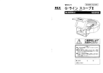
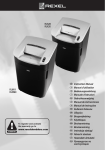
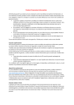
SERVICE MANUAL
MODELS:
GBC GLS28, GLX20, GLM11, GLHS9
REXEL RLS28, RLX20, RLM11, RLSM9
(2008.12.18)
© 2008 All Rights Reserved
No part of this publication
may be reproduced in any
form without expressed
written permission from
Electronically Printed
and Designed in the USA.
Table of Contents
INTRODUCTION
1
SPECIFICATIONS
INSTALLATION
2
TROUBLESHOOTING
3-7
DISASSEMBLY/ADJUSTMENTS
8-9
MAINTENANCE
10.0 SPECIAL INSTRUCTIONS
Introduction
Introduction
11
a
a
g
g
e
d
f
e
d
f
b
c
c
Models: GBC GLS28, GLX20 / REXEL RLS28, RLX20
a
b
c
d
e
f
g
Models: GBC GLM11, GLHS9 / REXEL RLM11, RLSM9
Indicator Panel
Door for Bin
Wheels
Power On Button
Auto Feed Button
Reverse Button
CD Slot
1
Illuminated Panel
1
2
3
4
b
Power On
Shredder not OK
Door Open
Bin Full
2
3
4
Specifications
2
Specifications
Models
GLS28
GLX20
Sheet Capacity -
28 sheets
20 sheets
Duty Cycle -
Continuous operation
Continuous operation
Volts / Hz
120V AC / 60Hz
120V AC / 60Hz
Amperage
8.0 A
10.0 A
Models
GLM11
GLHS9
Sheet Capacity -
11 sheets
9 sheets
Duty Cycle -
Continuous operation
Continuous operation
Volts / Hz
120V AC / 60Hz
120V AC / 60Hz
Amperage
10.0 A
8.0 A
Models
RLS28
RLX20
Sheet Capacity -
28 sheets
20 sheets
Duty Cycle -
Continuous operation
Continuous operation
Volts / Hz
230-240V AC / 50Hz
230-240V AC / 50Hz
Amperage
6.0A
7.0A
Models
RLM11
RLSM9
Sheet Capacity -
11 sheets
9 sheets
Duty Cycle -
Continuous operation
Continuous operation
Volts / Hz
230-240V AC / 50Hz
230-240V AC / 50Hz
Amperage
5.0A
5.0A
Specifications
5.0 TTroubleshooting
Mechanical Operation
The shredder uses two rotating cutting shafts,
which are driven by an electrical motor to shred
paper.
Electrical Operation
Bag Full Flap Switch - The flap switch is a normally
open switch actuated by the bag full flap. When the
shred bag becomes full of shredded material, the
bag full flap is pushed back and power is then
removed from the motor circuit.
When the center power on switch is pressed,
all the LED warning symbols on the indicator
The shredder will now
be in standby mode and the “Power-on” symbol
on the indicator panel will be illuminated amber.
When the shredder is in standby mode and the the
cabinet door is opend,the normally closed door
adjar micro switch is opened and prevents power to
the motor until the door is closed.. When the bag full
sensor is triggered, the bag full icon will illuminate.
The control board will then disable the motor circuit
until the shredder bag is either cleared or emptied.
Paper Sensors - Located in the throat area consisting of two components, the emitter and receiver.
When the shredder is severely loaded down, the
control board will illuminate red and disable the
motor circuit.
WARNING!
Always disconnect the power cord from receptacle
before making continuity or resistance tests.
Electrical Components
Switches
Set meter to read resistance. Check switches for
continuity from common to closed contacts and
ity from common to the open contact.
Motor - Thermally protected motor designed for
continous operation.
Capacitor - AC motor run capacitor.
Power on/Auto feed on switch - The Power on
/Auto feed on switch, when depressed, connects
the hot and neutral circuits to electrical components
of the shredder.
Door ajar, Machine head safety switch - The safety
switch is a normally open micro switch which is
actuated by a trigger located inside of the cabinet door.
The switch is normally closed when the door is
closed and when the machine head is installed on the
cabinet.
Emitter - The infrared light beam from the light emitting diode is sensed by the receiver to activate/deactivate the control board.
Receiver - The receiver is a light activated diode,
which works in conjunction with the emitter to activate/deactivate the control board.
Testing Electrical Components
Emitter - Set meter to the diode setting. Disconnect
emitters from the control board. With the positive
meter probe on the emitter wire and the negative
meter probe on the black-stripped emitter wire,
check for approximately .639 ohms. Reverse the
meter leads and
should be read.
Receiver - Set meter to read 20M ohms. Disconnect
the receiver from the control board. With the positive
meter probe on the receiver wire and the negative
meter probe on the receiver wire check for approximately 4.62 Mega ohms under normal room
light. The resistance will increase when blocked.
should be read.
Reverse the meter leads and
8
3
5.0 TTroubleshooting
General Troubleshooting
Troubleshooting Chart
Malfunction corrections are based on visual observations made by the operator. The causes of the
malfunctions are isolated by the symptom of the
malfunction and noting at which point in the operating cycle the malfunction occurred. Malfunctions
may be pinpointed to a defective electrical component or mechanical part by referring to the
Principles of Operation, the troubleshooting guide
and the wiring diagram.
The troubleshooting guide chart that follows is
arranged in order of the normal operational
sequence. When a malfunction occurs, read down
the approprithe SYMPTOM column until you
ate description for your symptom. Read the corresponding PROBABLE CAUSE, then perform the
recommended procedure in the CORRECTIVE
ACTION column. When replacing electrical components that have push on terminals, label the electrical leads that were removed, to facilitate reconnect
ing them. Refer to the wiring diagram on page 6
to resolve any wiring di culties that may occur.
WARNING!
Always unplug the shredder to avoid possible electrical shock hazard before attempting to perform
any repairs.
4
5.0
Troubleshooting
5
Shredder Does Not
Operate, No Indication Of
Power
Power Cord Disconnected.
Connect Power Cord
Power switch Defective
Main Board Defective
Replace Power Switch
Replace Main Board
Shredder Does Not
Operate, With Indication
Of Power Present
Shredder Head Not
Installed Properly
Reposition Shredder Head
Cabinet Door Open
Close Door
Shred Bag Full
Empty Bag
Motor Thermal Cut
Triggered
Allow Motor To Cool
Door Switch Defective
Replace Door Switch
Defective Capacitor
Replace Capacitor
Motor Defective
Check Motor Input Voltage
Replace Motor If Necessary
Emitter/Receiver Defective
Replace If Necessary
Main Board Defective
Replace If Necessary
Dust Or Scratch On
Emitter/Receiver
Clean Or Replace
Defective Control Board
Replace If Necessary
Emitter/Receiver Defective
Replace If Necessary
Dry Blades
Lubricate Cutters
Dull Cutters
Replace Cutters
Worn Bearings
Replace Bearings
Shredder Does Not
Operate, (When Paper Is
Present In The Throat)
Shredder Runs
Continuously
Sheet Capacity
Diminished
Troubleshooting
Power SW(PUSH) 16A/250VAC
SW5
Auto-Forward
6
LED4
LED3
LED1
LED2
S1
SW6
standy by(flash GREEN)&auto(GREEN)
Reverse
JAM&REVERSE(RED) Bin OPEN(RED)
panel board
1
2
3
4
5
6
7
8
1
2
JA1
CON3
8PIN/2.0
POWER1
5.08MM
8
7
6
5
4
3
2
1
2
1
C
Paper Trigger
Emitter
Incept
EMITTER
Photo LED
2.0mm/2p
1
2
3
4
5
Paper Trigger
1
2
5.08/5P
2.5mm/2p
CN1
BIN1A1
3P-2.0
2.5MM/4P
BIN2A1
2P/2.0MM
Bin Full
detection
CD Detection
sensor
SW4
COMMON
E
C
BIN FULL SW
NO
NC
Incept
EMITTER
Photo LED
Incept
EMITTER
Photo LED
Binfull Trigger
Photo
sensor(#5)
receiver
E
1
2
2
1
INDUCTION MOTOR
Main Board
C
3
1
TS1
3
2
1
E
2
M1
2
1
1
2
3
DOOR SAFETY SW
MOTOR CAP
NC
2
1
AC POWER1
NO
PCB box
CON2
8PIN/2.0
SW
4
3
2
1
SW2
COMMON
Power
DOOR SW1
LINE
AC POWER CORD
MOTOR CONNECTOR
NEUT
JA1
GND
Bin Full(red)
Troubleshooting
Reverse
Reverse
2
R18
C5
1
NEUTRAL
2
Forward
R25
Forward
1
47/0.5W
0.01U/250VAC
3
4
C8
U4B
QA5 SS8550
Reverse
5V SW
1N4148
5V SW
MOC3063
JAM1B1
1
U4C
5
3
QA2
TMG16C80
R28 4
1K 1/4W
3
R27
5
2.2K 1/8W
74HC14_2
Forward
E
C
PHOTO JAM DETECT
R14
10k 1/8w
1
2
3
SW2
COMMON
C12
D5
1.5K 1/8W + 1N4148
10UF/25V
C10
R22
R30
4.7UF/25V
47K 1/8W
1K 1/8W
Timmer
NO
TCO
NC
D8
DOOR SAFETY SW
R40
22K/1W
R40
51K/1W
R41
4.7K 1/8W
TCO detection
U4A
R40
1N4007
U25
EL-817
NEUTRAL
C14
0.1U/50V
door Open
D7
1N4004
74HC14
周期2mS
F1 T15A/250VAC
Line SW
F1 T10A/250VAC
U6
5V
7805 TO-220
3 I
O 1
D9
CX1
R35 470k/0.5W
GND
CY2
Input :USA:AC108Vac-132Vac/60Hz
Input:EU:AC207Vac-254Vac/50Hz
C25
R42
220k 1/2W
472/400V
NEUTRAL
IN4004
C25 33UF/50V
C25 22UF/50V
22UF/50V
C13
+
D18
IN4004
D16
IN4004
MOV 270V
G
C19
2UF/400V
V1
1
LINE
JA1
AC POWER CORD
0.47uF/275V
D17
C26
0.1U/50V
IN4004
R&C POWER SUPPLY
47K 1/8W
U26
EL-817
R33
10K 1/8W
U3B
5 +
7
6 -
C11 REF 3V
TCO SIG
LM393
0.1U/50V
+ C24
2
470K 1/2W
2
Power IN
R37
CY1
472/400V
C19 3.5UF/250V
C19 2.0UF/400V
5V SW
5VSW
R32
R31
100K 1/2W
NEUTRAL
F1
T10A,250VAC(NORMAL)
5VSW
R31 51K/1W
R31 100K/0.5W
2
1
51K/ 1W
1
R20
1k 1/8W
Power OUT
頻? 120HZ
R29
560 1/8W
JAM-1A1
+
SC1815
Motor jam
3P-2.0MM 5V SW
5VSW
R11
8
C7
0.1U/50V
5VSW
Q11
NEUT
9
1
2
3
TRAN
R26 6
470 1/4W
2
R13
10K 1/8W
R24
10K 1/8W U4D
74HC14
IR
UB2
R23 6
1K 1/4W
USE INFR DETECT MOTOR SPEED TO JAM
D3
Line SW
5V
3
R12
10k 1/8w
QA1,QA2 TMG25C60
QA1,QA2 TMG16C80
3.96MM (3-1)PIN
MOTORCAP1
5.08/5P
TO INDUCTOR MOTOR
R19
470 1/4W
2
8
Line SW
Line SW
1
3
5
QA1
TMG16C80
R21 4
1K 1/4W
2
1
2
3
4
5
5V SW
MOC3063
4
JA2
0.01U/250VAC
UB1
2
TC0
1
47/0.5W
MOTOR1
R17 6
1K 1/4W
7
220UF/35V
C27
220UF/16V
0.1U/50V
Title
Size
Date:
Large Office Shredder Main Board Motor Control Block
Document Number
Control Motor
Monday, October 27, 2008
Rev
V1
Sheet
2
of
6
Troubleshooting
8
Necessary Tools
Engine Assy. (Cutting Head Assy.) Removal
1. Adjustable wrench
2. #2 Phillips Screwdriver
Disassembly of the shredder is described in the following steps.
1
Top Housing Removal
2
2
2
1. Remove the six phillip head screws that secure the main pcb
box to the bottom base.
2. Remove pcb box front cover. Unplug and label all wires from
main pcb box.
WARNING!
Disconnect the unit from the receptacle before performing
any disassembly procedures.
1.Unplug the power cord from the outlet power supply.
2.Open cabinet door and remove the 3 phillip head screws that
secure shredder top cover to cabinet base.
3.Remove the 4 phillip head screws from the back side of the
shredder which secures top cover to cabinet base.
4. Lift top cover. Remove and label the 3 cables from control
panel.
3
3
3
3. Open cabinet door and remove the four (14 mm) hex nuts and
two wing nuts from the bottom base of engine (cutting head).
4. Carefully lift out engine ( cutting head ) assy and place
place on your work area.
5.0 Troubleshooting
Gear Box Removal
External Cleaning
Make sure you disconnect the shredder from its power source
before cleaning. The cover and cabinet may be cleaned with
a soft cloth moistened with a mild detergent and warm water.
Do not use chemical cleaners or solvents as these may have
a harmful e ect. Use detergent sparingly to avoid contact with
electronic components.
3
Inspection
Whenever the cover has been removed for corrective maintenance, visually inspect for defects such as loose screws or
nuts, damaged wire insulation, loose terminals, etc. Correct
any defects before returning the shredder into service.
2
1
1. Remove the six phillips screws from the gear box cover.
2. Remove the two 14mm bolts.
3. Remove the two phillips screws from the encoder housing.
4. Remove gearbox cover.
Motor Removal
1. Remove large double drive gear.
2. Remove small double drive gear.
5
3
4
3. Remove the Four phillip screws.
4. Remove the two 14mm bolts.
5. Remove support bar and replace motor.
9
Full Circle Service
10303 80th Avenue
Pleasant Praire, Wi 53158
TM
12/18/08