1
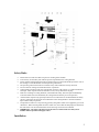
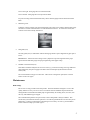
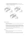
“When You Need More Than Staples.”
Toll Free: 800-658-8788
Fax: 801-927-3037
[email protected]
IDEAL CUTTERS
Model 4810 (18-3/4”)
Model 4810-11 (18-3/4”)
Model 5210 (20-1/2”)
1
Safety Rules
•
•
•
•
•
•
•
•
•
•
Ensure that at no time more than one person is working at the machine.
Leave the key for the safety lock with the person responsible for the cutting machine.
Power operated cutting machines must be operated only by trained and reliable personnel. Part of
the training is to become familiar with the operating instructions.
The operating instructions must be accessible at any time and must be strictly observed.
Do not reach into cutting area while the knife is in operation.
Change knife and cutting stick only with the main switch in “off” position. For other maintenance
and repair, which requires removal of machine covers, always disconnect the plug.
Defects in or damage to cutting machines, which affect the safety, must be repaired immediately.
Until such faults have been eliminated, the cutting machine must be put out of operation.
Annual routine inspection by specially trained service technicians are recommended for all safety
devices, particularly the electrical control measures in the cutting machine. Records should be
kept of these safety inspections.
Transportation of knives is only allowing specially designed wooden cases supplied by your local
distributor. When inserting knife into the wooden case, ensure that the sharp edge lies flush with
that side of the case into which the holes for the securing screws have been drilled.
IMPORTANT – The safety rules must be strictly observed. Please make sure that you are
familiar with the operation of the paper cutter.
Installation
2
The entire machine is dispatched in one package, but the stand (#7) and the hand wheel (#19) for
the paper clamp have been dismounted from the machine.
The tool box contains:
•
•
•
•
•
a set of tools for service and maintenance,
the mounting hardware for the stand,
the back gauge crank (#3) with a mounting screw,
two keys for the safety lock.
Place machine (#1) on stand (#2).
Insert securing bolts for the stand into provided holes and secure with nuts.
Place paper tray (#8) into the stand (#7).
Mount the hand wheel for the paper clamp (#19) and the crank for the back gauge (#3). Secure
these parts with provided screws.
Connect power cord with plug to a normal single phase AC socket.
The machine is now ready to be operated.
Performance
All paper qualities and light cardboard can be cut using the full cutting height and cutting length of
the machine.
4810
4810-11
Cutting Length
Cutting Height
Table depth
Narrow cut
475 mm
(18-3/4”)
80 mm
(3-1/8”)
460 mm
(18-1/8”)
30 mm
(1-3/16”)
5210
520 mm
(20-1/2”)
80 mm
(3-1/8”)
520 mm
(20-1/2”)
35 mm
(1-3/8”)
Features and Operation
•
Main Switch (#11)
3
Turn main switch (#11) to position “|” (on), in order to begin operation. The main switch can be
sued as an EMERGENCY SWITCH, which stops the machine immediately.
•
Safety lock with key (#6)
The key can be removed to prevent unauthorized use. To activate the machine, turn key 45º to the
right.
•
Re-set button (#12)
Before the knife can be activated on models IDEAL 4810 and IDEAL 5210, the re-set button has
to be pressed to re-establish the “ready to cut” status of the machine. The yellow pilot light in the
viewing window (#14) comes on and indicates, that the machine s is ready for use. The model
IDEAL 4810-11 does not have a re-set button.
•
Two-hand operation
Only by pressing the right and the left push button switch (#5) simultaneously (within half a
second), can a cut be executed. Keep push buttons (#5) depressed until the knife has reached it
lowest position. As soon as the push buttons have been released, the knife returns automatically to
its home position.
•
Automatic knife return
If a cut cycle is interrupted by releasing both push button switches (#5), the knife returns
automatically to its home position. IF only one of push buttons is released, the knife stops in the
reached position until the second push button is released as well.
•
Spindle clamp system
The clamp holds the paper pile in position while cutting. The paper clamp (#15) is lowered and
raised by turning the hand wheel (#19).
By turning the wheel clockwise: the clamp is lowered.
By turning the wheel counter clockwise: the clamp is raised.
The paper is clamped by tightening the hand wheel (#19) with a quick pull to the right.
IMPORTANT – Only by clamping the paper pile securely is precise cut guaranteed.
•
Back gauge (#22)
The back gauge is spindle-guided for easy and precise adjustment with the crank (#3).
When squaring the paper pile avoid using excessive force against the back gauge otherwise the
back gauge could be knocked fractionally out of the pre-set dimension and the guide piece of the
back gauge is subjected to unnecessary wear.
•
Back gauge crank (#3)
The crank is indirectly connected with the back gauge spindle. The crank is engaged by applying
slight pressure toward the machine. The connection is released by pulling the crank towards the
operator. If the crank is disengaged, the back gauge setting cannot be changed inadvertently.
4
Turn to the right: back gauge moves towards the knife.
Turn to the left: back gauge moves away from the knife.
For precise setting of the measurement always move the back gauge from the back towards the
knife.
•
Measuring scale
Under the viewing window (#14) the measurement scale rotates in accordance with the back gauge
movement. The exact measurement is to read beneath the indicator. To avoid inaccuracies, the
scale has to be read vertically from above.
•
Side guide (#16)
The side guide (#16) in combination with the back gauge allow a square alignment of paper pile to
be cut.
IMPORTANT – Please note that cutting accuracy depends on precise alignment of the paper
against the side and back gauges and proper tightening of the paper clamp.
•
Thermal overload switch (#10)
If the motor should be subjected to excessive strain (e.g. continuous cutting of strong cardboard
with a dull knife), the power supply to the motor will be interrupted by the thermal overload
switch (#10).
The overload button will pop out a few mm. After a short cooling down period, the overload
button can be reset again.
Maintenance
Knife change
Precise cuts are only possible with a sharp knife. The knife should be changed as soon as the
quality and the accuracy of a cut are not in accordance with the standards expected from this
cutting machine. Knife life with normal paper is approximately 20 working hours; of course, this
will vary with different types of paper.
We recommend the purchase of a spare knife, so that a sharp knife is always available. This
ensures that your machines remains operative even if the original knife has to be sent away for resharpening. Look for a professional re-sharpening service locally. Of course, your distributor
knows one and can help you in this regard.
5
The knife change must be executed by one person only. The cutting edge of the knife is extremely
sharp. In order to avoid injuries, the knife has to be handled with the utmost care. Transportation
of knife is only permitted in specially designed wooden cases, which are supplied with every spare
knife ordered from your local distributor.
The following description applies to model IDEAL 4810-11. Please note, that with models
IDEAL 4810 and IDEAL 5210 the re-set button (#12) must be pushed prior to activating the knife
with the two push buttons (#5).
1.
2.
3.
4.
5.
6.
7.
8.
Turn the cutting depth adjustment screw (#4) all the way to the left (-) and then a complete
turn to the right (+).
Bring the knife down by pressing both push button switches (#5). Release one of the switches
and turn main switch (#11) to position “0” (off). The knife stays in its lowest position on the
cutting stick (#2).
Remove knife screw (E). See illustration I.
Remove the securing screw (F) on the knife adjustment flap (#20). Lift up the flap (#20) and
turn out the three knife adjustment screws (X, Y, and Z) by approximately 5 mm (1 /4”). See
illustration II.
Turn main switch (#11) to position “|” (on). The knife carrier (#17) goes back to its home
position. Turn main switch back to “off” position.
Remove knife screws (B and D) and replace them with the two knife holders from the tool
box. Tighten securely.
Take out knife screws (A and C), loosen knife holders and lower the knife downwards from
the knife carrier (#17). Then, due to the length of the knife, a sideways movement between
the knife guide plates is required for removal.
Take out cutting stick (#2), turn, rotate or exchange it and place it back into machine.
IMPORTANT – Hook cutting stick into pin, which is located on left between the knife guide
plates.
9.
10.
11.
12.
13.
14.
Insert knife holders into second and fourth threaded hole (B and D) of the new knife. Ensure
that the ends of the knife holders are protruding from the other side of the knife. Place knife
(#18) into knife carrier (#17) and secure with knife holders.
Screw in knife screws (A and C) – snuggly, don’t tighten.
Remove knife holders. Screw in knife screws (B and D) – snuggly, don’t tighten.
Spread one to three sheets of paper across the entire cutting length. Bring the knife (#17)
down. Release only one push button (#5) and turn main switch (#11) to position “0” (off)
again to stop the knife in its lowest position.
Screw in knife screw (E) – snuggly, don’t tighten.
The parallel adjustment of the knife is done via the knife adjustment screws.
Push knife down by screwing in the knife adjustment screws (X, Y, and Z) evenly, until the
paper is cut across its whole length.
15. Should the scope of the adjustment available by means of the knife adjustment screws be
insufficient, resort to the knife depth adjustment screw (#4). Turn it in steps of half a turn
clockwise (+). After each step a test cut has to be executed. If the paper is cut through only
on one side, proceed with parallel adjustment of knife as described under (#12 and #14).
IMPORTANT – Both the above methods (#14 and #15) of knife adjustment offer an
adjustment range of approximately 5 mm (1 / 4”).
16. Tighten knife screws (B, C, D and E) firmly while the knife is lowered on the cutting stick.
17. Turn main switch (#11) to position “|” (on). The knife returns to its home position.
18. Tighten knife screw (A) firmly. Screw in securing screw for knife adjustment flap (#20).
6
19. Make a test cut with a paper pile using the full cutting height. If necessary do a final
adjustment with the cutting depth adjustment screw (#4).
20. IMPORTANT – The clamp bar must be adjusted in a way that the cutting edge of the knife in
its home position is covered by the clamp bar.
Changing of cutting stick
Should the bottom sheet of a paper pile not be cut across its full length, the cutting stick (#2) must
be turned, rotated or exchanged.
IMPORTANT – If the knife has been lowered by means of the cutting depth adjustment screw
(#6) to compensate for a worn cutting stick, then this adjustment screw (#6) has to be turned back
to its highest setting before the cutting stick (#5) is turned, rotated or exchanged. Then re-adjust
screw (#6) again to obtain the optimal cutting depth. A knife that is set too low can inflict damage
not only to the cutting stick, but also to the knife and the knife drive system.
The cutting stick (#2) is inserted into the machine table and fixed by hooking it into a pin located
on the left between the knife guide plates.
Lubrication
IMPORTANT – Before removing any machine covers for service or maintenance, always
disconnect machine from power supply.
From time to time all moving parts have to be oiled or greased. Before lubricating clean all parts
and ensure that they are free of paper dust and dirt. The following parts have to be lubricated:
7
1.
2.
3.
4.
The guide grooves and all other moving parts of the clamp assembly.
The knife carrier guide channels (left and right). They are located between the knife guide
plates.
All moving parts of the knife drive system. To reach these parts, the lower machine cover
(#9) and / or the front table (#13) must be removed.
The back gauge spindle, its housing points, and the back gauge guide mechanism.
The lubrication chart indicates all points to which “EP” grease or oil must be applied
A full lubrication of the machine is recommended at least once in every third knife change.
Wiring diagram
A wiring diagram for the machine is included in the electric switch box, which can be reached by
removing the front table (#13).
Troubleshooting
Should the machine cut out during operation, check the thermal overload switch (#10). If the
button of the thermal overload switch has popped out, it can be re-set after a short cooling period.
Should the thermal overload switch pop out again and cannot be re-set even after a few minutes,
please contact your service technician.
If the operator should detect any potentially dangerous defects, he should immediately call a
service technician and put the machine out of operation.
If defects or faults should occur which render repairs necessary, please contact your local
dealer.
8