1
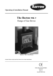
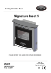
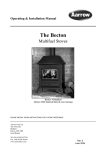
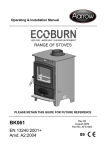
Installation / Servicing Instructions
& User Manual
Sherborne GSL
Conventional Flue Gas Stove
Sherbone GSL Natural Gas With Logs Shown
PLEASE RETAIN THESE INSTRUCTIONS FOR FUTURE REFERENCE
THIS STOVE IS NOT SUITABLE FOR TIMBER FRAMED PROPERTIES.
Arada Ltd
North Mills Industrial Estate,
Bridport,
Dorset,
United Kingdom
DT6 3BE
Tel (+44) 01308 427234
Fax (+44) 01308 423441
www.arada.uk.com
FOR USE IN COUNTRIES
GB & IE
Gas Council ID Number
NG - 32-248-06
LPG - 32-248-07
Rev 3
Nov 2006
Part No. AFGS1095
CONTENTS
SERVICING
INSTALLATION
Safety Notices
General Information
3
3-4
Replacement Of The Glass Frame
25-26
Burner & Valve Assembly Removal
26
Annual Service
27
Cleaning Outer Surfaces
27
Fault Diagnosis
28
Annual Service Record
29
Contents List & Part Identification
5
Important Notices
6
Statutory Requirements
6
Certification
6
Technical Data
7
Gas Fire Dimensions
7
USER INSTRUCTIONS
Installing The Stove
7
Lighting & Controlling The Fire
Preparation of the stove
8
Cleaning Outer Surfaces
Stove Location
8
Operation of Remote Control
Shelf Clearances
9
Important Notices
38
32-33
33
34-37
Flue System
10
Statutory Requirements
38
Fitting The Flue Spigot And Blanking Plate
11
Certification
38
Shelf Clearances
39
Rear / Top Flue Options
11-12
Connecting The Gas Supply
13
Pressure Test Sequence
13
Fitting & Arranging The Coals
14-15
Fitting & Arranging The Logs NG
15-16
Fitting & Arranging The Logs LPG
16-17
Installation of Remote Control System
18-21
Commissioning The Stove
Fire Testing
Installation Check List
2
SPARE PARTS
General Components
40-42
Options & Accessories
43
GUARANTEE
44
Final Factory Checklist
46
22
22-23
24
Aarrow Sherborne GSL CF
INSTALLATION INSTRUCTIONS
References in this manual to British Standards and
Statutory Regulations and Requirements apply only
to the United Kingdom. For Ireland the rules in
force must be used.
Before installation, check that the local distribution
conditions, nature of the gas, pressure and the
adjustment of the appliance are compatible.
The manual is an important part of the appliance
and must by law be handed to the end user on
completion of the installation.
SAFETY NOTICES
• Do not attempt to burn rubbish or any other
material in this appliance.
• Do not use the appliance if the glass is cracked or
broken.
• Do not make any unauthorised
modifications to the appliance.
• It is recommended that the stove be guarded
to protect the young and infirm using a
fireguard complying with BS8423:2002.
• Coal / Log set -The coal/log set contains
Refractory Ceramic Fibres (R.C.F), which are man
made vitreous silicate fibres. Excessive
exposure to these materials may cause
temporary irritation to the eyes, skin and
respiratory tract. Care must be taken when
handling these items to ensure the release of
dust particles is kept to a minimum. To
ensure that the release of fibre from these
items is kept to a minimum, during
installation and servicing it is recommended
that a vacuum cleaner fitted with H.E.P.A.
filters is used to remove any dust, soot or
any other debris accumulated in and around
the appliance. This should be performed
before and after the installation. It is
recommended that any replacement item(s)
are not broken up but sealed within a heavy
duty polythene bag and clearly labelled
"R.C.F. waste". This is not classified as
"hazardous waste" and may be disposed of
at a tipping site licensed for the disposal of
industrial waste. Protective clothing is not
required when handling these items but it is
recommended that gloves are worn and
normal hygiene rules are followed.
Always wash your hands before eating or
Aarrow Sherborne GSL CF
drinking.
• In the event of a gas emergency, consult the
telephone directory and ask for your local
gas supplier.
Guide to manual handling
• Always obtain assistance when lifting the
appliance.
• When lifting always keep your back
straight. Bend your legs not your back.
• Avoid twisting at the waist. It is better to
reposition your feet.
• Avoid upper body/top heavy bending. Do not
lean forwards or sideways when
handling the fire.
• Always grip with the palms of your hands.
Do not use fingertips for support.
• Always keep the stove as close to the body as
possible. This will minimise the cantilever
action.
• Use gloves to provide additional grip.
________________________________________
GENERAL INFORMATION
1. General Note
All materials and equipment used in the
installation of this stove should be fit for the
purpose, be of suitable quality and workmanship
and should comply with the applicable British
Standards, building regulations and rules in force.
2. Ventilation
No purpose provided ventilation is normally
required.
3. Flue Type
The stove is suitable for flue options with a
minimum diameter of 127mm (5”) and have a
minimum effective height of 3 metres (10ft) see
page 11 to 12.
4. Hazardous Materials
Asbestos, hazardous or any banned materials have
not been and will not be included in this product.
3
INSTALLATION INSTRUCTIONS
5. Stove location
See installation instructions on page 7.
6. Packed details
For packed weight see packaging labels.
Please Observe Unpacking
& Safety Warning Labels
Stove Specification Label
(Both Ends Of Box)
Fig 1
7.Unpacking note
When the stove is unpacked ensure no damage
occurs if placed on the carpet as it can leave indentation marks.
For contents list see page 5.
8. Fit for purpose
All materials, appliances and equipment used
should be fit for purpose, be of suitable quality and
workmanship and should comply with the
applicable British Standard.
9. Data Label Plate.
The data label plate is fixed to the underside of the
valve bracket assembly, and can simply be swung
in and out as required (see Fig 2a). Please observe
the data, safety and warning labels attached to this
plate. Do not remove this plate from the stove.
Fig 2a
4
Aarrow Sherborne GSL CF
INSTALLATION INSTRUCTIONS
CONTENTS LIST
ALL
TYPES
Main Box
Packed Inside Stove
STOVE ENGINE
•
Coal Set (NG & LPG) or
•
GLASS FRAME ASSEMBLY
•
Log Set (NG Only) or
•
DUMMY FUEL RETAINER
•
Log Set (LPG Only)
•
OPERATING INSTRUCTIONS
•
CANOPY COVER PLATE
•
CANOPY INFILL PIECE
•
HOT PLATE (BLANKING)
•
FLUE SPIGOT
•
OUTER BODY & CANOPY
•
FIRE DOORS
•
VALVE COVER
•
Flue Spigot
Hot Plate (Blanking)
Operating Tool
OPERATING TOOL
•
GAS SERVICE TAP & GLASS SCREWS
•
PART IDENTIFICATION
Canopy Cover Plate
Outer Body & Canopy
Canopy Infill Piece
Stove Engine Assembly
Glass Frame Assembly
Fire Doors
Dummy Fuel Retainer
Valve Cover
Fig 2b
Aarrow Sherborne GSL CF
5
INSTALLATION INSTRUCTIONS
IMPORTANT NOTICES
STATUTORY REQUIREMENTS
A qualified gas engineer must carry out the
installation and servicing of this appliance in
accordance with these instructions and in
compliance with current Building Regulations.
Such person must be a registered CORGI
engineer.
This appliance is designed to run on natural gas
(NG) or liquid petrolum gas (LPG) depending up
on the model purchased. Warning - Only use the
appliance with the specified gas.
The instructions must be read before use of the
appliance.
This product must be installed in accordance with
the rules in force.
Please note the following;
Detailed recommendations are outlined in the
current issue of the following British Standards:BS5440 parts 1 and 2, BS5871 part 1 and BS6891.
• Sealed components must not be interfered
with.
• Servicing instructions and part identification
numbers are given towards the back of the
manual.
• Only use genuine Aarrow parts for
replacements.
• Ventilation, no purpose built ventilation is
normally required, normal adventitious room
ventilation being suffient.
• Coal / log set, see safety notice on page 3 must be
observed.
All surfaces except the control knobs are
considered to be working surfaces.
The current Gas Safety (Installation and Use)
Regulations (as amended).
The Building Regulations for England and Wales
2000 ref Approved Document J 2002 edition
(issued by the DTLR).
The Building Standards (Scotland) (Consolidation)
Regulations.
Any Manufacturer's Instructions must not be
taken as overriding statutory requirements.
_________________________________________
CERTIFICATION
This appliance is CE certificated for performance
and safety. Therefore, it is important that no
alteration is made to the appliance.
Any alteration not approved by Arada Ltd will
invalidate the guarantee.
Warning: Under no circumstances must the fire
be operated if the glass is cracked or broken.
Warning: If
operational
appliance, it
investigated
engineer.
it is known or suspected that an
or ignition fault exists on the
must not be used until it has been
and corrected by a qualified gas
Warning: THIS GAS APPLIANCE MUST BE
SERVICED EVERY TWELVE MONTHS BY A
QUALIFIED GAS ENGINEER.
6
Aarrow Sherborne GSL CF
INSTALLATION INSTRUCTIONS
TECHNICAL DATA
Natural
Gas
LPG
Gas
Category
I2H
I3P
Supply
Pressure
20mbar
37mbar
Bray 82/400
Bray 82/160
Heat Input
(gross)
6.1 kW
5.7kW
Gas Rate
0.55m3/hour
0.21m3/hour
Gas Type
Injector
Max. Heat
Setting
Min. Heat
Setting
Heat Input
(gross)
2.5 kW
2.5kW
Gas Rate
0.23m3/hour
0.09m3/hour
Efficiency
Class
CLASS 2
CLASS 2
NOx Class
Unclassified
Unclassified
Country Of
Use
AT,DK,ES,FI,
GB,GR,IE,IT,
NO,PT,SE
ES,FR,GB,
GR,IE,IT,PT
Gas Council
Id Number
32-248-06
32-248-07
Table 1
Aarrow Sherborne GSL CF
Fig. 3
INSTALLING THE STOVE
A CORGI qualified gas engineer MUST install the stove
in accordance with the following regulations and standards:The Gas Safety (Installation and Use) Regulations
current edition.
The Building Regulations for England and Wales 2000
ref; Approved Document J 2002 edition (issued by the
DTLR).
The Building Standards (Scotland) (Consolidation)
Regulations.
BS5440 parts 1 and 2 BS5871 And these Installation
Instructions.
Warning: Failure to comply with the regulations,
requirements, or these instructions will invalidate the
guarantee and could have hazardous consequences.
IMPORTANT
Please note that in tight recesses the gas supply point
may be inaccessible. Therefore it may be necessary to
route the pipe for the gas supply before installing the
stove into its recess.
7
INSTALLATION INSTRUCTIONS
PREPARATION OF THE STOVE
Prior to starting the installation and after removing
the packaging, check that all the parts have been
supplied to the contents list on page 5.
Carry out the following:Step 1 Remove outer casing (disengage locking
levers see page 25, steps 1a /b, 2, 3, 4, and 5).
Step 2 Remove glass and retaining frame (see page
25 step 6).
Step 3 Remove the packaging from the coal / log set
and cut the cable tie retaining 8mm olive and valve
connection nut (located to the rear of valve assembly).
The stove must not be installed against a
combustible wall.
The stove must never be positioned closer than
100mm to any rear wall see Fig. 4a
The stove is NOT suitable for houses with timber
frame construction.
STOVE LOCATION
The appliance must not be installed in a room or
space, which contains a bath or shower.
This stove is designed for use with either top or rear
flue outlets and must be mounted on a hearth. The
hearth must be strong enough to support the stove.
For overall minimum hearth sizes see Fig.4a and
Fig.4b.
To comply with current Building Regulations the
stove must stand on a fireproof hearth which has a
minimum upper fireproof layer of 12mm non-combustible material. The rear of the stove is to be
100mm from the wall which must be of a non-combustible material.
The hearth must not be capable of inadvertent
covering by a carpet or rug. This should be
achieved by either:
•The hearth being 50mm above the
level of the room floor.
or •a 50mm high fender or kerb being
fixed around the edge of the hearth.
Ensure the hearth is level and flat.
Do not place any combustible material including
clothing, furniture and furnishings (including
curtains) within 1 metre of the stove.
For details of combustible and non-combustible
shelf clearances see graphs 1 and 2 on page 9.
The rear edge of the canopy cover must be fitted
flush against the wall.
It is acceptable to place the stove against plaster
board on dry line property.
8
X=100mm Minimum Distance
Y=See Graph 1 & 2
Fig. 4a
Side Clearances
A=100mm Minimum Per Side To A
Non Combustible Wall.
B=200mm Minimum Per Side To A
Combustible Wall.
Fig. 4b
Aarrow Sherborne GSL CF
INSTALLATION INSTRUCTIONS
SHELF CLEARANCES
Combustible shelf clearances
The minimum height from the extreme top surface of the stove to the underside of a shelf or other
projection made of wood or any other combustible material is shown on graph 1.
Graph 1
Non-Combustible shelf clearances
The minimum height from the extreme top surface of the stove to the underside of a shelf or other
projection made of non-combustible material is shown on graph 2.
Graph 2
WARNING: No shelf is to be used with a top flued appliance, where it has to pass through a shelf.
Aarrow Sherborne GSL CF
9
INSTALLATION INSTRUCTIONS
FLUE SYSTEM
The stove must be connected to a suitable and
efficient flue that provides a good updraught to
safely take the products of combustion (fumes)
from the stove outlet to the outside air. To ensure a
good updraught it is important that the flue gases
are kept warm and that the flue size suits the stove.
The termination of the outlet at the top of the flue
also needs to comply with the Building
Regulations. The minimum effective height of the
chimney must be at least 3 metres and when warm
the flue draught should be between 0.05 and 6mb
(0.5mm to 6mm water gauge).
The stove requires a minimum flue size of 125mm
(5 inches). The stove can be fitted to a
sound conventional solid fuel burning chimney
system (Class 1) provided it is swept.
The flue must be terminated with a suitable
chimney pot or cowl and the chimney or flue shall
be swept prior to installation unless the chimney is
clean and unobstructed.
The flue and chimney installation must be
carefully checked by a competent person before
fitting the stove to ensure it is suitable and will
work safely. The flue must also pass a Flue flow
test (smoke test) to BS 5440: Part 1.
For advice on flues and chimneys contact;
NACE (National Association of Chimney
Engineer): telephone 0800 0924019
www.nace.org.uk
or
NACS (National Association of Chimney
Sweeps): telephone 01785 811732
www.chimneyworks.co.uk
If the chimney is not sound or the chimney has an
internal flue size greater than 225mm (9 inches)
diameter or 200 x 200mm square, a 125mm (5
inches) diameter stainless steel flexible flue liner
complying with BS 715 should be installed in the
flue.
If a new chimney is being provided it should fully
comply with the relevant Building Regulation
Requirements and BS 5440: Part 1. Suitable types
of chimney include the following.
• Masonry chimney built with clay or concrete liners, or a chimney block system meeting Building
Regulations.
• Precast concrete gas flue block complying with
BS 1289: Part 1
Factory made metal chimney complying with BS
715 (often called "Twin wall Class 2 chimney") or
Factory made metal insulated chimney complying with BS 4543: Part 2 (often called "Class 1 prefabricated metal chimney"). To ensure the flue
gases are kept warm an insulated chimney system
should be used if the chimney is positioned outside
the building.
10
Aarrow Sherborne GSL CF
INSTALLATION INSTRUCTIONS
FITTING THE FLUE SPIGOT AND
BLANKING PLATE
Note: Blanking plate fitted to top flue outlet for
packing
The gas stove is designed so that the flue can be
fitted to either the top or the rear of the appliance.
Fit the flue spigot and blanking plate for either top
or rear flue outlet in accordance with figure 5a or
5b (below).
for checking for debris build up. Closure plates
must be sealed to the chimney or fireplace opening
with fire cement, fireproof rope or other suitable
high temperature mastic.
REAR FLUE OPTIONS
Open Hearth (See Figure 6-a page 12)
Fit and seal a ‘T’ section (with debris /soot
collector) directly into the flue spigot. Ensure it
passes through the closure plate by at least 102mm
(4”).
The maximum horizontal section allowed is
350mm.
Provide a minimum vertical height of 600mm of
flue from the height of the rear flue outlet.
Closure Plate (See Figure 6b page 12)
Fig. 5b
Fig. 5a
Lock the blanking hot plate in place by rotating
anti-clockwise and tighten by tapping gently with a
block of wood and mallet. Fit the spigot to the
unused opening in the same way. The units are
sealed by the attached gaskets.
Connect the flue spigot to the rear outlet then
connect a flue extension to the spigot up to a
maximum length of 350mm.
Fit and seal the closure plate into the fireplace
opening.
Position the stove so the flue extension passes
through the hole in the closure plate by at least
50mm.
Ensure all joints are sealed with fire cement or a
suitable high temperature sealant.
TOP FLUE OPTIONS
Top Flue (See Figure 6c page 12)
Provide a minimum vertical height of 600mm of
flue measured from the top of the appliance.
Position the stove, with flue spigot in place, into
position under the flue and seal the spigot/flue
connection with fire cement or a suitable high
temperature sealant.
Fig 5c
CLOSURE PLATES
It is recommended that a smoke test is performed
inside the stove to ensure that adequate flue draw is
evident after making the flue connection
If a closure plate is used for sealing off the chimney
or fireplace opening it can be made of metal (e.g.
aluminium sheet) or fireplace board (see figure 6
a/b/c on page 12) however provision must be made
Aarrow Sherborne GSL CF
11
INSTALLATION INSTRUCTIONS
Y=See Graph 1
Fig. 6c.
Fig. 6a
Fig. 6b
12
Aarrow Sherborne GSL CF
INSTALLATION INSTRUCTIONS
CONNECTING THE GAS SUPPLY
Once the stove is in place it is then possible to
connect the gas supply. The gas supply point is
located centrally at the rear (as show in fig.7) and
should be connected in accordance with the following requirements.
Gas Inlet
Rear Of
Valve
Fig. 8
PRESSURE TEST SEQUENCE
Controls are located at the base of the stove below
the ash lip.
Fig. 7
Check that the appliance is suitable for the gas
supply; refer to data labels on packaging and/or the
stove data label for the gas type.
The gas installation must be in accordance with the
current issue of BS6891.Gas supply pressure at the
fire should be 20mbar for natural gas & 37mbar
for LPG.
The gas supply should be connected with the 12mm
fitting and olive supplied with the stove.
A maximum pipe run of 1.5 meters (or 5 feet)
should be adhered to. Copper tubing may be used
provided a distance of 25mm is maintained
between pipe-work and any surface of the stove.
The gas service tap (supplied) should be fitted adjacent to the fireplace to enable safe removal of the
appliance for servicing. After fitting the supply,
operate the gas tap (supplied) and check all joints
up to the termination of the supply pipe for gas
tightness using a soap/water solution and the pressure drop method.
To check the pressure to the burner. This must be
carried out with all other gas appliances operating
at maximum. To check the pressure to the burner it
is necessary to ignite the appliance and set to 'high
rate'. (See pressure test sequence).
Aarrow Sherborne GSL CF
Ensure supply is isolated and the valve is in
the off position
Step 1. Remove the valve control cover by
unscrewing the pozi screw located by knob B and
lever the retaining tab to the side of knob A.
Step 2. Locate the outlet pressure tap and unscrew
approximately half a turn anti-clockwise with a
small flat bladed screw driver. Connect a pressure
guage to the outlet pressure tap.
Step 3. Re-connect the supply and light stove. (see
lighting and controlling the stove section in the
users instructions section of this manual). Turn to
high setting. Read pressure guage, setting to be 20 mbar for Natural Gas or
37 mbar for LPG
Step 4. If any adjustment is required, use the brass
screw located between knob B and knob A on the
front of the valve, and adjust accordingly to the
indication symbol marked upon the valve body.
Step 5. Turn off stove and isolate the supply.
Step 6. Disconnect manometer and re-tighten the
outlet pressure tap screw. Do not over tighten.
Step 7 Replace the valve control cover.
13
INSTALLATION INSTRUCTIONS
FITTING AND ARRANGING THE
COALS (Both NG & LPG versions)
Centre Coal
Position
Pilot
Notch
Ensure the appliance is cold
Safety Notice - Please see SAFETY NOTICES
ref. Coal / Log sets page 3.
Warning: The coals and the coal matrix are fragile
ensure they are handled carefully.
Ensure location is correct. Do not force the matrix
into position. If the coals and/or the coal matrix are
damaged they must be replaced with genuine
Aarrow parts.
Warning: An incorrect coal layout may cause soot
to build up inside the stove and therefore invalidate
the guarantee.
Fig. 10a
3) Now position one of the loose coals into the
centre of the stove ensuring that it is placed into
the centre cutout and when in position, this coal
will be resting upon the four corners of the base
matrices. See Fig. 10a & b.
RR
LR
RF
LF
Fig. 10b
11X
LOOSE
COALS
Fig. 9
How to arrange the coals
(see Fig 9 for part identification)
Plan View Of Base Matricies - White Dots
Indicate Loose Coal Positions / Cut outs.
4) Next, take 6x coals and place along the front
row of the base matrices, 3x to the left of the centre coal and 3x to the right of the centre coal.
Observre the cutout positions within the matices
as shown in Fig. 10b & 10c.
1) Place the 2x larger base matrices at the rear of
the burner. These are labelled LR (left rear) & RR
(right rear). These should be positioned so that the
slots in the matrices sit over the rear upright fold of
the burner top plate.
2) Next position the 2x smaller base matrices
between the rear matrices and the front of the firebox. These matrices are labelled, LF (left front) &
RF (right front). The RF matrix has a notch in the
front to avoid the pilot assembly.
The arrangement should look like Fig 10a.
14
Fig. 10c
5) Take the remaining 4x coals and place along
the upper edge to the base matrices. Again, place
the coals into the areas shown in Fig 10b. The
coal set layout is now complete and should look
like Fig 10d & 10e.
Aarrow Sherborne GSL CF
INSTALLATION INSTRUCTIONS
Key For Contents To NG Log Set A = Rear log matrix (black in colour)
B = Loose Embers (bagged)
C = Curved Log
D = Y Shape Log
E = Central Log (Knotted Lump Protruding)
F = 3x Small Twigs
G = 1x Large Twig
Fig. 10d
How to arrange the logs
1) Position the rear log matrix in the centre at the
rear of the burner. The base of the matrix should
slot down behind the burner. See Fig. 12a.
Fig. 10e
Plan View Of Coal Set Layout.
Note - Ensure that the pilot light is visible through
the slot in the front right base matrix and that the
pilot flame is not impinged.
FITTING AND ARRANGING THE
LOGS (NG ONLY)
Ensure the appliance is cold
Safety Notice - Please see SAFETY NOTICES
ref. Coal / Log set, page 3.
Warning: The logs and matrix are fragile, ensure
they are handled carefully.
Ensure location is correct. Do not force the matrix
into position. If any of the logs and/or rear matrix
is damaged, they must be replaced with genuine
Aarrow parts.
Warning: An incorrect log layout may cause soot
to build up inside the stove and therefore invalidate the guarantee.
A
2) Lay the Y shape log to the right hand side of
the burner. Ensure that the Y open section is upper
most and is resting onto the cutout flat area to the
right of the rear log matrix. The base should be
approimately 30mm from the front of the stove
window opening. See Fig 12a.
3) Take the curved log and place this to the left
hand side of the burner. Make sure that the base of
this log is again approx. 30mm from the front of
the stove and the upper end of the log is resting on
the grooved notch within the rear log matrix. See
Fig 12a. Note, there should be a gap between both
side logs when resting correctly on the rear
matrix.
4) Next scatter the loose embers onto the burner
area. Take care not to obstruct the pilot assembly.
B
Fig. 12a
C
F
E
Fig. 11
Aarrow Sherborne GSL CF
G
D
5) Lay the central log, from the centre front of the
burner to the rear of the stove. Sitting the upper
portion of the central log onto the edge of the
15
INSTALLATION INSTRUCTIONS
upper corner of the curved left hand log. See Fig.
12b. Note, the top resting position of the central
log is angled to the left.
FITTING AND ARRANGING THE
LOGS (LPG ONLY)
Ensure the appliance is cold
Fig. 12b
6) Place 2x smaller twigs as shown in Fig. 12b.
Note, the bottom of the twigs rest between the
stove body and burner. Take care with the right
hand twig to avoid impinging upon the pilot
assembly.
7) Take the remaining small twig and large twig
and place as shown in Fig 12c. The log layout is
now correct.
Safety Notice - Please see SAFETY NOTICES
ref. Coal / Log set, page 3.
Warning: The logs and matrix are fragile, ensure
they are handled carefully.
Ensure location is correct. Do not force the matrix
into position. If any of the logs and/or rear matrix
is damaged, they must be replaced with genuine
Aarrow parts.
Warning: An incorrect log layout may cause soot
to build up inside the stove and therefore invalidate the guarantee.
D
B
A
C
F
G
E
Fig 13
Fig. 12c
Key For Contents To LPG Log Set A = Y Shaped Rear Log
B = Loose Embers
C = Curved Log
D = Straight Log
E = 1x Medium Twig
F = 3x Small Twig
G = 2x Large Twigs
How to arrange the logs
1) Position the Y shaped log across the rear of the
burner, standing up against the rear of the firebox
and behind the burner. See Fig. 14a.
2) Scatter the loose embers over the burner, taking
care not to cover the pilot assembly. See Fig. 14a.
16
Aarrow Sherborne GSL CF
INSTALLATION INSTRUCTIONS
5) The remaining 3X small twigs are placed as
shown in Fig. 14d. The LPG log layout is now
complete.
Fig. 14a
3) Place the curved log to the left hand side of the
firebox, rest the top of this log onto the top of the
Y shaped open end of the rear log. Take the
straight log and position this to the right hand side
of the firebox, again rest the rear of this log onto
the rear Y shaped log, opposite end to the curved
log. Note, rest both fronts of these end logs
against the front corners of the burner.See Fig.14b.
Fig. 14d
Fig. 14b
4) Next place the 2x large twigs into the layout
with the base of each twig central about the stove
opening and placed to the front of the stove. The
tops of these twigs radiate out from the base to
form a vee shape and rest upon the rear Y log (left
hand) and straight log (right hand). The medium
twig is placed between the large twigs as shown in
Fig. 14c.
Fig. 14c
Aarrow Sherborne GSL CF
17
INSTALLATION INSTRUCTIONS
NOTE: If the optional remote control system has been ordered with the stove and is not
fitted please proceed.
FOR A MANUAL STOVE (WITHOUT REMOTE CONTROL) PROCEED TO PAGE 22.
INSTALLATION OF REMOTE CONTROL SYSTEM
Important
• A corgi registered gas engineer must carry out the installation of the remote control system
PARTS LIST
1
2
3
4
5
6
Motor
Ultrasonic Receiver
Remote control handset
Wiring Harness (Multiblock end to reciever, spade connections to motor/micro switch)
Micro-switch
AA/LR6 1.5v Batteries (4x) & 9V-6F22 9v Battery (1) Supplied (Not Shown)
4
1
2
5
3
Fig. 15
Technical data
Ambient temperature range Remote and receiver max. 140deg F / 60deg C
Connecting cable
max. 356deg F / 180deg C
Batteries
Quality Alkaline
Handset: 1x9V Block
Receiver: 4x1.5V AA
18
Aarrow Sherborne GSL CF
INSTALLATION INSTRUCTIONS
ASSEMBLE MOTOR
1) Remove the front cover from the valve. This is done by unscrewing the small pozi screw, located by
knob B. Unclip the right hand side of the cover located to the side of knob A. See Fig. 16a & b.
Tab
Screw
Knob B
Knob A
Fig. 16a
Fig. 16b
2) Remove the cover and dispose of the spacer tube fitted with the screw.
3) Position the motor onto the location lugs (arrow X) and engage the drive gear onto knob B (arrow Y).
X
Y
Fig. 16c
Fig. 16d
4) Replace valve cover, ensure clip is located before the pozi screw is tightened. Do not over-tighten the
screw as this may effect the operation of the control.
5) Take the micro switch and fix to the front of the valve cover with the self tapping screw provided.
Switch is located onto the lug moulded within the valve cover, next to knob B. See Fig. 16e.
Wiring
Connections
Knob B
Micro Switch
Fig. 16e
Aarrow Sherborne GSL CF
19
INSTALLATION INSTRUCTIONS
ASSEMBLE RECEIVER
Important
The remote system is intended for use with original Aarrow parts only.
1) Carefully push the multi block connector on to the connection within the reciever unit as shown in Fig
17a. This connector can only fit one way, so ensure the slot in the recievers board lines up with the moulding within the multi block connection.
SLOT
Fig. 17a
Fig. 17b
2) Next, connect the angled spade connectors to the motor, note there are two different sized connectors and
these can only be fitted to the appropriate sized spade tab. The remaining narrow spade connectors fit to the
spade tabs on the micro switch. These are not handed, see Fig. 17b.
3) Place the double sided adhesive tape to the underside of the reciever unit. Slide back the cover and insert
the 4x AA/LR6 1.5v batteries into unit, observing the correct polartity as marked on the unit. Re-place
cover. Fig. 17c.
CAUTION! Ensure the batteries are inserted AFTER the motor is wired. A short circuit can
destroy the electrical components.
4) Position the reciever unit, as shown in Fig. 17d onto the space provided on the valve bracket. Affix the
underside of the unit with the double sided tape. Take care to route the wiring harness away from any hot
parts and do not obstruct the valve controls. The reciever unit works by ultrasonic so ensure that the recieving round grill is facing to the front of the stove.
Fig. 17d
Fig. 17c
20
Aarrow Sherborne GSL CF
INSTALLATION INSTRUCTIONS
HANDSET
1) Insert the battery (9v) into Remote control. Slide back the battery compartment cover, insert and connect
a suitable battery and replace the cover.
Fig. 18
2) The remote is now ready to use. In the event of battery failure the flame height can still be adjusted manually using the knob B on the valve.
NOTE
Please note, the placement of the Remote control (temperature sensor) is important to assure
proper temperature regulation. Please refer to user instructions.
Aarrow Sherborne GSL CF
21
INSTALLATION INSTRUCTIONS
COMMISSIONING THE STOVE
Refit the glass/glass frame assembly.
Refit the outer body and secure with the locking
levers.
If horizontal flue is used fit the canopy cover
plate. (See page 25 step 1a.)
If top flue is used locate the infill plate (See page
25 step 1b).
Follow the lighting instructions (See pages 32 &
33), light the pilot and check:1. The operation of the control
2. The cross lighting of the burner
3. All gas settings can be achieved
Repeated operation of the spillage monitoring
system whereby the OSD (oxygen sensing
device/spillage monitoring system). If their is a
problem with the ODS pilot going out after the
stove has operated satisfactory, this indicates a
possible flue draw problem. Seek expert advise
from a qualified engineer.
Warning: The spillage monitoring system,
consists of a special oxygen sensing device (OSD)
pilot and is a safety feature required by law. It
must not be adjusted or put out of action by the
installer. If the spillage monitoring system or
any of its parts are to be replaced, only original
manufacturers parts must be used.
FIRE TESTING
Flame failure device testing
Step 1 Ignite the appliance in accordance with page
and run for 60 seconds.
Step 2 Turn the appliance off to extinguish the
pilot, listen for a snap at the control valve. This
should occur within 60 seconds of the pilot flame
being extinguished. The snap sound will be the
magnet disengaging, and thus shutting off the flow
of gas to the pilot and burner.
Spillage Test
Step 1. Close all doors and windows.
Step 2 Light the appliance and set to the high rate.
Step 3. Allow fire to warm up for 10 minutes.
Step 4. Position the smoke match at the back of the
fire centrally beneath the rear diverter as shown in
Fig 19a.
Fig. 19a
Note: The fire will give off non-toxic fumes when
first used. This is perfectly normal it will disappear
after the first few hours. Once the spillage test is
complete open windows and doors to ventilate the
area.
SELF LEVELING REAR FEET
Once the stove is in position on the hearth, working
on the rear legs, simply loosen the pozi screw and
rotate the inner ‘pear’ shaped adjuster to touch the
hearth. Re-tighten the screw and repeat for the
other side.
All of the smoke should be drawn into the fire.
If this does not occur the appliance must be
disconnected and the flue checked.
Step 5. If there is an extractor fan in any room, this
must be turned on and any doors between it and the
fire left open, repeat the spillage test.
22
Fig. 19b
Aarrow Sherborne GSL CF
INSTALLATION INSTRUCTIONS
Advise the end user
1. That there will be an odour from the stove
when the stove is first lit and is non-toxic. It is
advised that the stove is initially run with the
room well ventilated to disperse the fumes.
2. How the valve controls operate and how to light
the pilot.
3. Advise about leaving pilot on.
4. That the stove is fitted with two safety devices,
one cuts off the stove if for any reason the gas
supply is turned off - A flame failure devise.
The second will cut the stove off if there is
inadequate flue draw for example a blockage in
the chimney. If this occurs the stove should not be
re-lit until the stove and flue have been checked
by a qualified gas engineer.
5. To read the users instructions before using the
stove.
6. The stove must never be used if the glass is
cracked or broken.
7. Explain that the working surfaces of the stove
will get hot and that no combustible materials
including clothing, furniture and furnishings
(including curtains) must not be placed within one
metre of the stove.
Leave the instruction manual with the end user
Aarrow Sherborne GSL CF
23
INSTALLATION INSTRUCTIONS
CHECKLIST
Hearths, Fireplaces, Flues and chimneys
This checklist is to ensure hearths, fireplaces, flues and chimneys are satisfactory, and to show what you have done to comply with the
requirements of The Building Regulations 2000 Approved Document J 2002.
1. Building address, where work has been carried out.......................................................................................................................................
.........................................................................................................................................................................................................................
2. Identification of hearth, fireplace chimney or flue
3. Firing capability: solid fuel/gas/.
4. Intended type of appliance.
State model and output.
5. Ventilation provisions for the appliance:
State type and area of permanently open vents.
6. Chimney or flue construction
a) State the type or make and whether new or existing.
b) internal flue size (and equivalent height, where
calculated - natural draught gas appliances only).
c) If clay or concrete flue liners used confirm that they are
correctly jointed with socket end uppermost and
state jointing materials used.
d) If an existing chimney has been refurbished with a
new liner, type or make of liner fitted.
e) Details of flue outlet terminal and diagram reference.
Outlet Details:
Complies with:
f) Number and angle of bends.
g) Provision for cleaning and recommended frequency.
7. Hearth. Form of construction. New or existing?
8. Inspection and testing after completion
Tests carried out by:
Tests and results
Flue
inspection
visual
sweeping
coring ball
smoke
Appliance (where included) spillage
I/we the undersigned confirm that the above details are correct. In my opinion, these works comply with the relevant requirements in
Part J of Schedule 1 to the Building regulations.
Print name and title....................................................................................................Profession..........................................................................
Capacity......................................................................................................................Telephone..........................................................................
Address............................................................................................................................................................Postcode.......................................
Signed........................................................................................................Date.................................
Registered membership of..(e.g. CORGI, OFTEC, HETAS, NACE, NACS)............................................
24
Aarrow Sherborne GSL CF
SERVICING
REPLACEMENT OF THE GLASS
Step 4 Lift the body and canopy off the chassis.
Refer to “guide to manual handling” on page 3.
IMPORTANT
When refitting the glass frame ensure the original screws are used. Longer screws may foul
the coal / log set placement.
Ensure the appliance is cold.
Step 1a For rear flue appliance remove canopy
cover plate.
Step 5 Remove dummy fuel retainer (2 screws)
If glass is broken, suitable gloves must be worn
for protection.
Step 1b For top flue appliance remove infill piece.
Step 2 Remove the fire doors
Open and lift off hinges (held shut by magnet).
Step 6 Remove glass and glass frame.
• Remove any loose glass
• Be aware of any glass that will become loose
when removing the frame.
•Loosen but do not remove the four screws at the
base of the frame.
•Remove all but one of the top centre retaining
screws.
Step 3 Disengage locking levers, one per side.
•Remove the remaining top screw. The frame and
glass will now be loose and can be removed.
•The frame has slots at the base to ease removal.
•Remove any remaining loose glass.
Aarrow Sherborne GSL CF
25
SERVICING
Step 7 Clear inside of stove of any debris.
Step 7 Remove the two self tapping screws each
side of the injector as shown below.
Step 8 To re-assemble reverse this procedure. See
initial note on page 25.
Note:When relocating the body and canopy
assembly ensure the front location tab is engaged
in the chassis.
The burner assembly may now be
removed. Slide back off the injector and
lift the burner assembly upwards from the
rear while at the same time pivoting it
towards you. Take care not to damage the
injector.
BURNER AND VALVE
ASSEMBLY REMOVAL
Please note! When handling the burner assembly
be aware of the sharp points of the self tapping
screws on the underside
Ensure the appliance is cold.
Step 1 Isolate the gas supply from the stove
Step 2 Disconnect the supply inlet pipe by
releasing the pipe nut at the rear of the
valve, see page 13.
Step 8 To remove the valve assembly undo the
3x Pozi M5 screws, located within the fire
box (2x to the front of the burner and 1x
centrually to the rear of the burner), lift
upwards from the rear while at the same
time pivoting it towards you. Carefully
guide the controls through aperture clear
of the stove.
After replacement of burner assembly, ensure
that a check on the gas tightness of any new
joint is carried out.
Step 3 Remove the outer body of the stove (Ref
Page 25).
Step 4 Remove the dummy fuel retainer and then
the glass frame assembly (Ref Page 25).
Step 5 Remove the coals or logs.
Step 6 Remove the base coal matrix (four pieces)
Take care not to damage the matrix,
(Page 14).
26
Aarrow Sherborne GSL CF
SERVICING
ANNUAL SERVICE
THIS GAS APPLIANCE MUST BE SERVICED
EVERY TWELVE MONTHS BY A QUALIFIED
GAS ENGINEER.
See "SAFETY NOTICES" ref coal set page 3.
Ensure the appliance is cold.
Step 1 Isolate the gas supply from the stove.
Step 2 Remove the outer body of the stove.
Step 3 Remove the glass.
Important: If the glass is broken or cracked or
the glass gasket is damaged they must be
replaced before the stove is used.
Step 4 Carefully remove and clean the loose coal
/ logs set of any soot deposits using a soft
brush.
Step 5 Clean the firebox of any soot deposits
using a soft brush.
Step 6 Carefully lift out and clean the base coal
matrix. Important: If any of the ceramic
components are damaged they must be
replaced with original Aarrow parts.
Step 7 Clean the burner top and surrounding
areas with a vacuum cleaner.(See safety
notices on page 3).
Step 8 Inspect the pilot assembly to ensure that it
is clean, unobstructed and in good work
ing order.
Step 9 Looking into the flue from inside the
stove check that it is clear of any debris or
obstructions.
Step 10 Check the system for gas soundness.
Step 11 Check the ignition of the pilot and with
the pilot turned off check that the flame
failure system is working.
Step 12 Relocate the base coal matrix (4x piece).
Step 13 Relocate and position the loose coals or
re-assembly the log set.
Step 14 Light the pilot and check the operation of
the stove and the flame picture.
Step 15 Relocate the glass frame assembly,
ensuring all the screws are replaced and
secure. (Use original screws only.)
Aarrow Sherborne GSL CF
Step 16 Refit the dummy fuel retainer.(2x screws)
Step 17 Relocate the outer body of the stove.
Step 18 If the stove is rear flued proceed to fit the
top flue cover plate into the canopy
cutout ensuring the front tab is located
under the canopy (see page 25, step 1a).
Place the valve cover in front of the
control valve.
Step 19 If the stove is top flued, proceed to fit the
top flue infill piece (see page 25, step
1b). Place the valve cover in front of the
control valve.
CLEANING OUTER SURFACES
It is best cleaned using a soft brush. Do not allow
moisture to remain on the top while cold or
surface rust may occur.
27
SERVICING
FAULT DIAGNOSIS
START
Does the pilot
ignite?
Does the pilot
stay alight?
Yes
Yes
Does the main
burner light?
Does the stove
stay alight?
Yes
Yes
Fire satisfactory
Is the gas supply
turned on?
Is their air in
the system?
No
Yes
Is the main
injector blocked?
Purge system
Yes
Is the supply
pressure
correct?
No
Turn gas
on
Is the
thermocouple
o.k.?
No
Correct
pressure
Is their a spark at the
No
electrode?
Yes
Check if gas
is passing
from control
valve.
Yes
No
No
No
Clean and
replace as
necessary
Check gas supply and operation of
control valve. Replace if necessary.
No
Is pilot flame the correct
size & playing onto
thermocouple
Yes
Check for
spark output
from control
valve.
Yes
Investigate for blocked chimney
and adaquate ventilation check
spillage. If their is no obvious
blockage, seek expert advise.
Replace pilot
assembly
OSD
Yes
Yes
No
No
No
No
No
Confirm supply
pressure is correct
Replace the pilot
OSD assembly
Replace pilot
OSD assembly
Replace
control
valve
OSD
PILOT Oxygen
Sensing
Device
Pilot
Investigate control valve
operation and replace if necessary.
Replace pilot
OSD assembly
28
Aarrow Sherborne GSL CF
ANNUAL SERVICE RECORD
Date of Visit
Company
Work Carried Out
Signature
Should you have any questions about your Sherborne GSL Gas Stove that is not covered in this manual please
contact your Aarrow stove retailer.
Please keep all repair receipts safely.
Please ensure you have this manual available when an engineer visits as they will complete the service record
chart.
Aarrow Sherborne GSL CF
29
ADDITIONAL NOTES
30
Aarrow Sherborne GSL CF
USER
INSTRUCTIONS
Aarrow Sherborne GSL CF
31
USER INSTRUCTIONS
LIGHTING
THE FIRE
&
CONTROLLING
Under no circumstances must the stove be operated
if the glass is cracked or broken.
It is recommended that if the property is occupied
the pilot be left on permanently. This will keep the
stove and its components, including the ceramic
coal / log set in a warmer state and assist the lighting of the burner. This in turn will reduce the
chance of condensation and any associated problems.
If the property is left unoccupied for a long period
of time the pilot must be switched off.
The controls are located beneath the ash lip at the
base of the appliance. (See Fig.20a)
Note: Ensure burner control knob “B” is set at
maximum and pilot control knob “A” is set in the
off position. (See Fig. 20e)
Fig. 20a
Step 1. To ignite the pilot. First locate the pilot, it
can be viewed in the front right hand side of the
coal / log bed. Open doors and look downward
through the glass window 50mm from the right
hand side. To ignite the pilot turn control knob “A”
anti-clockwise towards the spark position (See Fig.
20b) until it stops, press down and hold in for 5 seconds. (only pilot gas flows) .
Continue pressing down while turning knob “A”
anti-clockwise to the small flame position, this will
activate the piezo and light the pilot. Continue to
hold down for a further 10 seconds after pilot has
been lit, if the pilot does not stay lit repeat the procedure. When the pilot stays lit release knob “A” at
the small flame position. (See Fig. 20c).
B
A
Fig. 20c
NOTE! This lighting procedure does not have to be
carried out every time the stove is used provided
the pilot is left alight.
Step 2. To ignite burner
With the pilot lit turn control knob “A” to the large
flame position and release. This will ignite the
burner. (See Fig. 20d) On initial lighting or after a
period of non use, there may be a short delay of 5
or 6 seconds to allow the burner chamber to fill
with gas, before ignition takes place, this is perfectly normal.
To achieve the desired setting turn knob “B” to suit.
Turn anti-clockwise to increase input and clockwise to decrease input.
Max
Min
Fig. 20d
NOTE! Between the Max and Min burner settings
an infinitely vairable flame height is achievable.
B
A
Fig. 20b
32
NOTE! Condensation may form on the glass
panel during initial ignition of the burner, this is
normal and due to the moisture in the atmosphere.
This will disappear within 10 minutes of firing.
Aarrow Sherborne GSL CF
USER INSTRUCTIONS
Step 3. To turn the stove and the pilot off
completely, turn control knob “A” to the small
flame setting, (pilot frame) depress and turn to off
position, then release (See Fig. 20e)
CLEANING OUTER SURFACES
It is best cleaned using a soft brush.
Do not allow moisture to remain on the stove while
cold or surface rust may occur.
A
B
Fig. 20e
Important, when control knob “A” is turned to the
off position a built-in safety lock is activated which
will prevent you from turning the control knob for
60 seconds.
Do not try to force the control, wait the 60
seconds.
NOTE! If the pilot flame is extinguished either
intentionally or unintentionally, no attempt to relight the gas should be until at least 3 minutes has
elapsed.
NOTE! During the initial firing, the stove will
give off non-toxic fumes when first used. This is
perfectly normal and will disappear after the first
few hours. It is advised to ventilate the room by
opening doors and windows to prevent irritation to
to user.
NOTE! The fire doors can be opened during operation, for a greater viewing area to the flame picture, this does not effect the operational performance of the stove.
NOTE! During operation, the metal surface of the
stove will be HOT, a operating tool is supplied
with the stove and can be used to open the doors if
required. See fig. 20f.
Fig. 20f
Aarrow Sherborne GSL CF
33
USER INSTRUCTIONS
NOTE: ONLY FOR STOVES WITH REMOTE CONTROL SYSTEM
TEMPERATURE DISPLAY REMOTE CONTROL
Display
A
Auto
Timer
B
Fig. 21
When the pilot has been lit, the remote transmitter can be used to control the flame height or to turn the main
burner on or off.
Aim the remote transmitter at the control valve and press the top button 'A' to increase the input or the bottom button 'B' to decrease the input. Short tapping of either button allows incremental change in flame height.
Note! In the event of battery failure the flame height can still be adjusted manually
Caution!
It is recommended to turn the combination control either to the off or pilot position if the appliance is left
unattended for long periods (e.g vacation) so that it cannot receive commands from the remote transmitter.
Exercise caution when leaving the appliance unattended, and in exceptional cases sound waves from sources
other than the transmitter can cause changes in flame height adjustment.
34
Aarrow Sherborne GSL CF
USER INSTRUCTIONS
THERMOSTAT AND TIMER REMOTE CONTROL
TRANSMITTER FUNCTIONS
Set the display (from *C/24 h to *F/12 h and vice versa)
• After connecting the battery or by simultaneously pressing AUTO and TIMER, the display flashes you
are in set mode.
• From set mode, press AUTO to switch from *F (and 12 hour clock) to *C (and 24 hour clock)
• The display will automatically return to manual mode after some time, but you may immediately return
ual by depressing the TIMER button.
Set the current time
• After connecting the battery or by simultaneously pressing AUTO and TIMER, the display flashes you
are in set mode.
• From set mode, press ( A ) to set the hour and ( B ) to set the minute.
• Wait or press TIMER to return to “manual” mode.
Programming the Desired Set Temperature
• Press AUTO until the display flashes
• Press ( A ) or ( B ) to the desired temperature.
• Wait or press AUTO to switch to automatic mode.
• A sensor in the remote control measures the room temperature. The controller compares the room temperature with the set temperature and sends a signal to the receiver to turn the gas valve motor, which adjusts
the flame height accordingly.
Programming the Timer
• Press TIMER until P1* (start) flashes (period 1. heating cycle on).
• Set the time for the beginning of the first heating period by pressing ( A ) for hour and ( B ) for minute.
• Press TIMER again P1* disappears and the symbol P1) (finish) appears.
• Set the time for the end of the first heating period.
• Press TIMER again to set the second heating period P2* (start) and P2) (finish).
• Store both heating periods by pressing TIMER again.
NOTE! If only one heating period is desired, programme the same time for P2* and P2) as for P1* and
P1).
Aarrow Sherborne GSL CF
35
USER INSTRUCTIONS
Manual Mode (Man in Display) for Manual Flame Height Adjustment
• Press ( A ) to turn on the fire (main burner) or to increase flame height.
• Press ( B ) to decrease the flame or to turn down to pilot.
• To incrementally increase or decrease the flame height lightly tap either the ( A ) or ( B ) button.
• The “Send” symbol appears in the upper left corner of the display when either large button is depressed.
• The LED of the remote control reciever flashes when knob B of the valve reaches its end stops.
Automatic Mode (AUTO in display) for Temperature Control
• Briefly press AUTO. The set temperature will appear briefly before the display reverts to the room temperature.
Timer Mode (TIMER in display)
• During heating periods P1* and P2* the temperature is continued in the same manner as in automatic mode.
• When the timer programme turns to P1) or P2) (heating cycle off) the motor will turn the valve to pilot and there is
no temperature control. This minimizes battery consumption.
• You may press AUTO to verify the set - temperature and then press TIMER to return to timer mode.
• You may press either the ( A ) or ( B ) button from any mode for manual override.
• To prolong battery life we recommend switching the remote control to manual mode and turning the fire to pilot
with the ( B ) button before turning the appliance off. If the remote control is left in automatic or timer mode, the
batteries will continue to be used when the appliance is off.
Changing the Battery
• If BATT appears in upper right hand corner of the display or if the red light of the receiver becomes faint please
change the battery from remote control or receiver.
Fig. 22
Slide back the handset battery compartment cover, remove the used battery, insert and connect a suitable battery (9V6F22) and replace the cover.
36
Aarrow Sherborne GSL CF
USER INSTRUCTIONS
Fig. 23
Slide back the battery compartment cover, insert 4 suitable batteries and replace the cover
If the batteries lose power, the flame height can be adjusted by manually turning knob B (see page 32)
NOTE
Please note the placement of the remote control (temperature sensor) is important to assure proper temperature regulation. Generally a more constant temperature will be assured, if the remote control is not too far
from the gas appliance. Before switching to AUTO or TIMER mode press either button ( A ) or ( B ) to
verify the reception (when the send symbol appears in the remote control display, the receiver red light
must illuminate). For the AUTO or TIMER mode to function correctly the remote control must remain
within range of the receiver. The remote control should not be used in very close proximity to the receiver
(less than 1m / 3ft) as this could in very rare cases, produce a electronic switch error. This error could block
the motor when the knob reaches the end points of its turning radius. The knob must then be turned manually to free blockage.
The temperature is controlled by activating the motor for a specific length of time to adjust the appropriate
flame height. This time is calculated by the remote control and depends on variables such as room size,
heater capacity, battery power etc. Therefore a few cycles are necessary before an optimum is achieved. If a
low flame is sufficient to provide enough warmth to the room, then the appliance will cycle between low
fire and off. This allows longer periods with the flame on and provides a more uniform room temperature.
It is recommended to turn the combination control either to the off or pliot position if the appliance is left unattended for longer
periods (e.g vacation) so that it cannot receive commands from the remote control. Exercise caution when leaving the appliance
unattended, in exceptional cases sound waves from sources other than the remote control can cause changes in flame height
adjustment.
Aarrow Sherborne GSL CF
37
USER INSTRUCTIONS
IMPORTANT NOTICES
A qualified gas engineer must carry out the
installation and servicing of this appliance in
accordance with these instructions and in
compliance with current Building Regulations.
Such person must be a registered CORGI
engineer.
This appliance is designed to run on natural gas or
LPG, however it is not possible to change between
the two versions without a factory service.
Warning - Only use the appliance with the specified gas (see the appliance data plate).
This appliance is intended for use on a gas installation with a governed meter.
The instructions must be read before use of the
appliance.
Warning: The stove will become very hot. Always
use a fire guard in the presence of children, the
elderly, and the infirm. The fireguard must
comply with BS8423:2002 (Fire guards suitable
for use with solid fuel appliances).
Warning: No combustible materials including
clothing, furniture and furnishings (including
curtains) must not be placed within 1 metre of the
stove.
Warning: THIS GAS APPLIANCE MUST BE
SERVICED EVERY TWELVE MONTHS BY A
QUALIFIED GAS ENGINEER.
STATUTORY REQUIREMENTS
This product must be installed in accordance with
the rules in force.
Please note the following;
• Sealed components must not be interfered
with.
• Servicing instructions and part identification
numbers are given towards the back of the
manual.
• Only use genuine Aarrow parts for
replacements.
All surfaces except the control knobs are
considered to be working surfaces.
Please note, that the monitoring system (ODS)
operates if evacuation of the combustion products
is interupted. If this does occur, turn the appliance
to the fully OFF position, and re-light (see page
32). If this monitoring system continues to cut out
the appliance, a qualified gas engineer should be
called.
Warning: Under no circumstances must the
stove be operated if the glass is cracked or
broken.
Warning: If
operational
appliance, it
investigated
engineer.
38
it is known or suspected that an
or ignition fault exists on the
must not be used until it has been
and corrected by a qualified gas
The current Gas Safety (Installation and Use)
Regulations (as amended).
The Building Regulations for England and Wales
2000 ref Approved Document J 2002 edition
(issued by the DTLR).
The Building Standards (Scotland) (Consolidation)
Regulations.
Detailed recommendations are outlined in the
current issue of the following British Standards:BS5440 parts 1 and 2, BS5871 part 1 and BS6891
.
Any Manufacturer Instructions must not be taken
as overriding statutory requirements.
_________________________________________
CERTIFICATION
This appliance is CE certificated for performance
and safety. Therefore, it is important that no
alteration is made to the appliance.
Any alteration not approved by Arada Ltd will
invalidate the guarantee.
Aarrow Sherborne GSL CF
USER INSTRUCTIONS
SHELF CLEARANCES
Combustible shelf clearances
The minimum height from the extreme top surface of the stove to the underside of a shelf or other
projection made of wood or any other combustible material is shown on graph 1.
Graph 1
Non-Combustible shelf clearances
The minimum height from the extreme top surface of the stove to the underside of a shelf or other
projection made of non-combustible material is shown on graph 2.
Graph 2
WARNING: No shelf is to be used with a top flue appliance, where it has to pass through a shelf.
Aarrow Sherborne GSL CF
39
SPARE PARTS
Part Description
Visual Aid
(not to scale)
Part Number
1. Coal set
(Complete)
AFGS1115
2. Log set - NG
(Complete)
AFGS1117
3. Log set - LPG
(Complete)
AFGS1121
40
4. Injector NG BRAY 82/400
AFGS1123
5. Injector LPG BRAY 82/160
AFGS1124
6. Pilot assembly NG
AFGS1087
7. Pilot assembly LPG
AFGS1125
8. Top Burner
Assembly NG
AFGS1126
9. Top Burner
Assembly LPG
AFGS1127
Aarrow Sherborne GSL CF
SPARE PARTS
Part Description
Visual Aid
(not to scale)
Part Number
10. Control Valve
AFGS1089
11. Fire door set
(with handles)
AFGS1128
12. Glass Frame
Assembly
AFGS1093
13. Hinge Kit &
With FixingsAFS047
14. Dummy Fuel
Retainer
AFGS1118
15. Instruction
Manual
AFGS1095
16. Stove Glass
Rope Gasket
AFGS1096
Aarrow Sherborne GSL CF
41
SPARE PARTS
Part Description
Visual Aid
(not to scale)
Part Number
17. Top Flue Cover
Plate
AFGS1098
18. Top Flue Infill
Piece
AFGS1120
19. Valve Cover
20. Flue Spigot
Complete With
Rope Gasket
21. Hot Plate
Complete With
Rope Gasket
AFGS1119
AFGS1129
AFGS010
22. Aarrow Fires
Gauntlet Gloves
AFS997
23. Operating Tool
AFS008
24.
42
Aarrow Sherborne GSL CF
OPTIONS & ACCESSORIES
Remote Control A remote control system can be retro-fitted to your Sherborne GSL stove. This system allows
convenient control of the stove, room temperature regulation and the advantage, to be programmable to
enable switching on / off by a timer function*.
* Note - Pilot must be lit manually before function of remote control is operational.
Part Code REMOTESHB
Paint Matching aerosol paint to tone in any connecting flues, pipes or surrounding metalwork.
Tracery Gothic style door traceries are available to suit any room.
Part Code TRACESHB
Add On Canopy A traditional raised add on canopy is available for your Sherborne GSL stove to complete the
authentic look. The canopy can simply be fitted once the stove has been installed.
Part Code AOCSHB
Aarrow Sherborne GSL CF
43
GUARANTEE
Your Sherborne GSL stove carries a Liftime* guarantee against defects to the stove body. All other
components carry a guarantee period of One year from the date of purchase . This does not apply
to items which would be subject to fair wear or tear. However, should you have any problems with
your appliance please contact your Aarrow stove stockist who will have the knowledge and facilities to help you.
*Lifetime Guarantee, stove body being defined as the steel outer casing and items fixed immovably to the casing.
Arada Ltd will not be responsible for any consequential or incidental loss, damage, or injury
however caused. If your appliance proves to be defective as a result of faulty materials or
workmanship during guarantee, we will repair or replace it FREE OF CHARGE as long as the stove
has been installed according to the these instructions and by a CORGI Registered fitter, who has
completed and signed the Installation Check List on page 24. The stove must also be serviced in
accordance with these instructions and the record of Annual service on page 29 should be completed
by your service engineer.
USE OF SPARE PARTS OTHER THAN THOSE SUPPLIED BY Arada Ltd WILL
INVALIDATE THE APPLIANCE WARRANTY.
All Guarantee periods commence on the date of purchase and are non-transferable.
Our Guarantee is offered as an addition to your statutory rights.
Guarantee applicable to original purchaser only. Not transferable.
The Manufactures decision shall be final.
This installation and operating manual gives sufficient details to enable the appliance to be installed
and maintained. If further information is required, please contact your local stockist who will be
pleased to help.
When you contact them, they will need to know :
1. Your name, address, post code and telephone number.
2. Date of purchase and supplier details.
3. Name of installer.
4. Stove serial number, found on the data plate badge.
5. Clear and concise details of the fault.
Please complete the following for you own records
Date of Purchase.............................Model.................. Serial Number.................................
Name and address of supplier.........................................................................................................
.........................................................................................................................................................
.........................................................................................................................................................
Name and address of Installer.........................................................................................................
.........................................................................................................................................................
.........................................................................................................................................................
44
Aarrow Sherborne GSL CF
ADDITIONAL NOTES
Aarrow Sherborne GSL CF
45
FINAL FACTORY ASSEMBLY CHECK LIST
Model..................................
Serial No.............................
ALL
TYPES
QUALITY
I’ve checked it
and it’s O.K.
FINISH
REGISTRATION CARD
INSTRUCTION MANUAL
GAS SERVICE TAP &
8x GLASS FIXING SCREWS
Assembled by.............................
Checked by ................................
FLUE SPIGOT OUTLET
HOT PLATE
OUTER SLAB CANOPY COVER
OUTER SLAB CANOPY INFILL
OUTER BODY ASSEMBLY
FIRE DOORS & HANDLES
DUMMY FUEL RETAINER
VALVE COVER
GLASS FRAME ASSEMBLY
SELF LEVELING FEET
OPERATING TOOL
OPTIONAL EXTRA
REMOTE CONTROL
DOOR TRACERY
FUEL BED SELECTION
NG / LPG COAL SET
NG LOG SET
LPG LOG SET
BK047