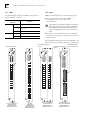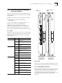
1
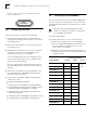
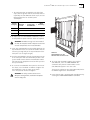
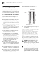
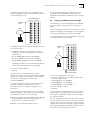
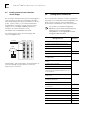
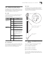
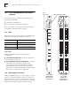
®
1.0
CoreBuilder® 5000 SwitchModule
Quick Start and Reference
Introduction
The 3Com CoreBuilder® 5000 SwitchModule is a LAN
switching module for the CoreBuilder 5000 Integrated
System Hub. The SwitchModule is available in several
media configurations and in single-slot and dual-slot
models.
Before you unpack the SwitchModule, read Section 3.0,
"Installation Prerequisites" and Section 5.0, "Installation
Precautions".
WARNING: CoreBuilder 5000 SwitchModules must
be installed only by trained service personnel.
2.0
Learning About SwitchModules
This document provides the basic information that you
need to install and configure a 3Com CoreBuilder 5000
SwitchModule at software Version v3.0.
3.0
Before you begin the SwitchModule installation process,
read the hardware and software requirements in this
section.
In addition to reading this document, be sure to
read the Release Note for CoreBuilder 5000
SwitchModules.
3.1
■
CoreBuilder 5000 SwitchModule User Guide
■
CoreBuilder 5000 Distributed Management Module
User Guide for software Version v6.00 or later
■
CoreBuilder 5000 Distributed Management Module
Commands Guide for software Version v6.00 or later
Tools Required
You need a flat-blade screwdriver to install the
CoreBuilder 5000 SwitchModule in the hub.
3.2
Hardware Prerequisites
1 Ensure that the CoreBuilder 5000 hub has at least one
of the following management modules installed:
■
For more detailed information about using the
SwitchModule, see the following documents:
Installation Prerequisites
■
6000M-MGT Distributed Management Module,
Version v6.00 or later
6000M-CMGT Advanced DMM/Controller Module,
Version v6.00 or later
2 Ensure that the CoreBuilder 5000 hub has the following
controller module installed: 6000M-RCTL Controller
Module, Version v1.15 or later
You can view these documents online with the 3Com
DocsOnCD documentation CD-ROM that comes with this
product.
To order hard-copy documents, contact your network
supplier, or call 3Com Corporation at 1-800-724-2447 and
choose the Customer Operations option.
Part Number 10013592
COREBUILDER® 5000 S WITCHMODULE Q UICK START AND REFERENCE
2
3 Ensure that the CoreBuilder 5000 hub contains either a
PacketChannel or a SwitchChannel backplane.
3.3
Software Prerequisites
Before you install a new SwitchModule:
To verify that the hub has one of these backplanes,
enter the command SHOW HUB. The model number
displayed in the Hub Type field should end in C
(SwitchChannel) or P (PacketChannel), and one of these
backplanes should be listed under Backplane Type.
1 Determine the DMM module’s software version status.
Enter the SHOW MODULE ALL command.
> show module all
The following display appears:
For example:
> show hub
Slot
Hub Information:
Hub Type: 6017C-AC
Backplane Information:
Backplane Type
--------------
Revision
--------
Load-Sharing Power Distribution module
Enhanced TriChannel Backplane
RingChannel Backplane
SwitchChannel Backplane
0
1
0
2
If your hub does not have an installed PacketChannel or
SwitchChannel backplane and you require
communication among SwitchModules, contact 3Com
or your 3Com representative to order a backplane
upgrade kit.
4 Use the following table to determine the slot
restrictions that apply to your hub configuration:
Backplane Type
PacketChannel
Hub Type
17-Slot
10-Slot
Installation Guideline
Install SwitchModules in any
slot.
7-Slot
SwitchChannel
(PacketChannel
plus ATM
Cell-Switching)
17-Slot
10-Slot
Slots 9, 10, 11, and 12 are
reserved for the
CoreBuilder® 5000 ATM
Switch/Control Point Module
(Model Number 3C96416SW).
Slots 9 and 10 are reserved for
the CoreBuilder 5000 ATM
Switch/Control Point Module
(Model Number 3C96416SW).
If you are installing only one SwitchModule, you can
install it in any slot, including a reserved ATM slot. The
single SwitchModule acts as a stand-alone switch.
If your hub does not have an installed PacketChannel or
SwitchChannel backplane, you can install only one
SwitchModule per hub.
Version
Network
----- -------
Module
-------
-------- -------------
10.01 6100D-MGT
v1.00
ETHERNET_1
11.01 6000M-RCTL
v1.15
N/A
Active
Ctrl Module
12.01 6000M-ARCTL v1.15
N/A
Stndby Ctrl
Module
12.02 6000M-AMGT
N/A
Master Mgmt
Module
v6.00
General Info
2 Look in the Version column to get the DMM software
version. The new SwitchModule functions incorrectly if
the DMM software version is wrong.
As shown in the previous display example, the
Advanced DMM/Controller (Model
Number 6000M-CMGT) appears as two modules in the
same slot (Model Numbers 6000M-ARCTL and
6000M-AMGT). The DMM operational code version is
displayed in the Version field of the -AMGT module.
4.0
Crucial Download Procedure
Review the following procedures before you attempt to
download software to any SwitchModule in your hub.
You must use the following procedures if you have
66xx family SwitchModules installed in your hub.
4.1
Download Procedure for SwitchModules
Earlier than Version v2.02 and DMMs
Earlier than Version v5.00
Use the following procedure for all SwitchModules in your
hub that are earlier than Version v2.02, and DMMs that
are earlier than Version v5.00.
CAUTION: All bridge port communication ceases if
you use an incorrect download procedure to
upgrade your SwitchModule and Distributed
Management Module (DMM) and Advanced DMM
(A/DMM) software. If you use an IP relay for
connectivity to download code to the DMM, that
connection also stops.
COREBUILDER® 5000 S WITCHM ODULE QUICK START AND REFERENCE
For ease of reading and because the DMM and
A/DMM are basically the same, the term DMM is
used in this release note to refer to both modules.
CAUTION: Do not upgrade to any later version until
instructed to do so in Step 5.
3
3 Download ATM SwitchModule software Version v3.00
operational code to all ATM Backbone SwitchModules
in the hub. The ATM SwitchModule model number is
3C96602M-MOD.
4 Upgrade all DMMs in the hub to software Version
v6.00.
See the CoreBuilder 5000 Distributed Management
Module User Guide, Chapter 11, for information
about DMM downloading.
5 Install the new SwitchModule into your hub. (See
Section 7.0, "Installing the SwitchModule".)
CAUTION: Do not install the new SwitchModules
yet.
6 Download the Version v3.00 software code to the new
SwitchModule.
To use the Frame Tagging feature, you must upgrade
all SwitchModules in the hub to software Version
v3.00 or later.
1 Upgrade all DMMs in the hub to software
Version v5.00.
2 Download SwitchModule boot software Version v1.05
to all SwitchModules in your hub.
3 Download SwitchModule software Version v3.00 to all
SwitchModules in your hub, even if they are already
running Version v3.00.
4 Download ATM Backbone SwitchModule software
Version v2.05 boot code, and then Version v3.00
operational code to all ATM Backbone SwitchModules
in your hub. The Model Number is 3C96602M-MOD.
5 Upgrade all DMMs in your hub to software Version
v6.00.
5.0
Electrostatic discharge (ESD) can damage static-sensitive
devices on circuit modules. Follow these precautions:
■
Do not remove the SwitchModule from its antistatic bag
until you are ready to inspect or to install it.
■
Handle the SwitchModule by the front panel only; do
not hold it by the component board.
■
Use proper grounding techniques when you install the
SwitchModule. These techniques include using a foot
strap and a grounded mat, wearing a grounded static
discharge wrist strap, or touching the metal rack or
frame just before you handle the SwitchModule.
6 Install the new SwitchModule into your hub. (See
Section 7.0, "Installing the SwitchModule".)
7 Download the Version v3.00 software code to the new
SwitchModule.
To use the Frame Tagging feature, you must upgrade
all SwitchModules in the hub to software Version
v3.00 or later.
4.2
Download Procedure for SwitchModules
at Version v2.02 or Later and DMMs at
Version v5.00 or Later
If your hub contains any SwitchModules that are at Version
v2.02 or later, and DMMs at Version 5.00 or later,
complete the following download procedure:
CAUTION: Do not install the new SwitchModules
yet.
1 Download SwitchModule boot software Version v1.05
to all SwitchModules in the hub.
2 Download SwitchModule software Version v3.00
operational code to all SwitchModules in the hub.
Installation Precautions
When you handle CoreBuilder 5000 SwitchModules,
follow these precautions to avoid component damage:
■
Do not twist or force the SwitchModule into the hub
when you insert it into the module guides.
■
Match the upper and lower module guides while you
slide the SwitchModule into place.
■
Do not push the SwitchModule all the way into the hub
until the SwitchModule ejectors (if any) are open.
WARNING: To ensure optical safety when you install
10BASE-FB/FL, FDDI, and 100BASE-FX
SwitchModules, comply with the following
precaution:
Although the data communication LEDs and Lasers
used in this product meet the regulatory
requirements for casual exposure to the eye, as with
any source of bright light, it is advised that you do
not look into the light source.
4
COREBUILDER® 5000 S WITCHMODULE Q UICK START AND REFERENCE
IEC 825, Class 1 LED Device. For connection only to
Class 1 LED Devices.
CLASS 1
LED PRODUCT
6.0
Unpacking Procedure
Follow this procedure to unpack a SwitchModule:
1 Verify that the SwitchModule is the model that you
ordered by examining the model number on the side of
the shipping carton.
7.0
Installing the SwitchModule
You do not need to turn off the CoreBuilder 5000 hub to
install or remove the SwitchModule. You can install the
SwitchModule while the hub is operating (which is called a
hot swap).
Before you start the installation process, read
Section 3.3, "Software Prerequisites," and Section
5.0, "Installation Precautions".
To install a SwitchModule:
1 Determine hub power. To ensure that the hub has
enough power to support the new SwitchModule:
2 Remove the SwitchModule, in its antistatic bag, from
the shipping carton.
a Enter the SHOW POWER BUDGET command to see if
sufficient wattage is available from the +5 volt,
–5 volt, and +12 volt supplies.
3 Following the instructions in Section 5.0, "Installation
Precautions", remove the SwitchModule from the
antistatic bag and inspect it for damage.
b Using the values in the following table, add up the
total power requirements for the SwitchModules that
you plan to install:
If the SwitchModule appears to be damaged, return it
to the antistatic bag, repack it in the shipping carton,
and contact your local supplier.
Keep the shipping carton and antistatic bag in which
your SwitchModule was shipped for future storage or
shipment.
Power Requirement at
Model Number
+5 Volts
–5 Volts
3C96618M-TX-A
52 W
0.5 W
3c96620M-TP-A
25 W
0.5 W
3C96612M-TP-A
23 W
0.5 W
4 Record the serial number of your SwitchModule. Use
the CoreBuilder 5000 SwitchModule Planning Chart
that comes with this product.
3C96624M-TP-A
30 W
0.5 W
3C96624M-TPL-A
25 W
0.5 W
5 Ensure that the CoreBuilder 5000 SwitchModule Kit
contains these items:
3C96616M-BTP-A
35 W
1.0 W
CoreBuilder 5000 SwitchModule
3C96610M-F-A
33 W
0.5 W
■
■
Release Note for CoreBuilder 5000 SwitchModules
3C96620M-F-A
50 W
0.5 W
3Com DocsOnCD documentation CD-ROM (contains
CoreBuilder 5000 SwitchModule User Guide)
3C96614M-FTP-A
30 W
0.5 W
3C96612M-FF-A
40 W
0.5 W
3C96604M-F-A
31 W
0.5 W
3C96612M-FC-A
57 W
0.5 W
3C96604M-TX-A
34 W
0.5 W
3C96604M-FX-A
35 W
0.5 W
■
■
CoreBuilder 5000 SwitchModule Quick Start and
Reference (this guide)
■
CoreBuilder 5000 SwitchModule Command Reference
■
CoreBuilder 5000 SwitchModule Planning Chart
+12 Volts
0.25 Watts
for all
modules
COREBUILDER® 5000 S WITCHM ODULE QUICK START AND REFERENCE
5
c The total watts that are available in the hub (from
step a) must be greater than the total watts that are
required by the SwitchModules (from step b). Use the
following worksheet to calculate power
consumption:
Voltage
Category
Watts
Available
in Hub
Watts
Required by
–
SwitchModule
=
+5
–
=
–5
–
=
+12
–
=
Watts
Remaining
2 To expose slots for SwitchModule installation, remove
as many blank faceplates from the chassis as required.
WARNING: Hazardous energy levels exist inside of
the hub. Do not place hands or objects into the hub
or touch components on an inserted module.
3 Insert each SwitchModule into the module guides at the
top and bottom of the selected slot and slide it into the
chassis by pressing firmly at the top and bottom of the
front panel (see the figure at right).
4 Lock the SwitchModules into place by applying pressure
to the front panel with one hand while you close each
ejector handle. Ensure that the SwitchModule remains
fully seated in the backplane connector while you close
the ejector handles.
5 To secure the SwitchModule front panel to the front of
the chassis, use a flat-blade screwdriver to tighten the
top and bottom screws to torque specification
3 to 5 inch pounds. Do not overtighten.
WARNING: For safety reasons and to ensure
adequate cooling airflow, install blank faceplates
over all empty slots.
Slide the
SwitchModule into the
selected slot as shown here.
6 To ensure that the DMM recognizes the installed
SwitchModule, enter the SHOW MODULE ALL
command. Verify that the model number of the
SwitchModule appears in the correct slot.
There may be a delay (no more than 30 seconds) before
the DMM recognizes the SwitchModule.
7 Ensure that the hub is operating with enough power by
entering the SHOW POWER BUDGET command.
6
8.0
COREBUILDER® 5000 S WITCHMODULE Q UICK START AND REFERENCE
Basic Configuration Steps
The following figure shows the default configuration
with three SwitchModules installed in the hub:
This section uses network configuration examples to
introduce important concepts about implementing
CoreBuilder 5000 SwitchModules in your network. Your
network configuration may be more or less complex than
the network configuration examples that are shown here.
8.1
SwitchModules in
slots 2, 3, and 4
DMM in
slot 1
Default Configuration After Installation
After you install one or more SwitchModule into the
CoreBuilder 5000 hub, the default configuration is as
follows:
■
All SwitchModule ports are assigned to virtual bridge 1.
This assignment means that all SwitchModule ports can
communicate with all other SwitchModule ports,
regardless of the slot in which they reside, and subject
to the slot restrictions that are described in Section 3.2,
step 4.
■
All SwitchModule ports are automatically connected to
the switching backplane in the hub (either
PacketChannel or PacketChannel with Cell-Switching).
You do not need to enter a command to assign ports to
the backplane, as other CoreBuilder 5000 media
modules may require.
■
■
Ethernet Backplane SwitchModule backplane ports
(ports 17 through 24) are permanently connected to
shared Ethernet backplanes 1 through 8.
All SwitchModule ports (except Ethernet Backplane
SwitchModule backplane ports 17 through 24) are
enabled and capable of switching traffic if you attach
devices to the ports. You must enable Ethernet
Backplane SwitchModule ports 17 through 24 using the
DMM command SET BPORT_MAU MODE ENABLE or
SET PORT MODE ENABLE. For information about the
special port numbering system that applies to these
ports, see Chapter 4 in the CoreBuilder 5000
SwitchModule User Guide.
■
The Spanning Tree Protocol is enabled on virtual
bridge 1 and on all SwitchModule ports. Spanning Tree
parameters are set to their default settings, which are
described in Chapter 7 in the CoreBuilder 5000
SwitchModule User Guide.
■
Frame Tagging is disabled. For more information about
frame tagging, see Chapter 8 in the CoreBuilder 5000
SwitchModule User Guide.
■
The maximum vbridge value is set to 32, which means
that you can assign ports to virtual bridges 1 through
32. To change this value, see Chapter 2 in the
CoreBuilder 5000 SwitchModule User Guide.
Virtual bridge 1
8.2
Enabling SNMP Management Through the
SwitchModule
Configure IP settings for a virtual bridge only if the DMM
has no other means of IP connectivity.
For example, you do not need to configure IP settings if
the hub contains an Ethernet media module with a
network monitor card (NMC) attached to it. The NMC
provides connectivity between SwitchModules and the
DMM.
If you do not already have an in-band connection to the
DMM, and you want to manage the hub from a network
management station (NMS) that is connected to a
SwitchModule port, use the instructions in this section.
CAUTION: Although the DMM supports multiple
IP addresses, enable the interface for only one
address per subnet (on the network that is attached
to your default gateway). Enabling multiple
IP interfaces on the same subnet may cause
connectivity problems.
When a model A SwitchModule (the model number
ends in -A) is installed in the hub, include at least
one of its ports in the virtual bridge that is acting as
the IP relay interface. For example, if there are five
virtual bridges, and if you are managing the hub
through virtual bridge 1, ensure that virtual bridge 1
includes at least one of the model A SwitchModule’s
ports.
COREBUILDER® 5000 S WITCHM ODULE QUICK START AND REFERENCE
The following figure shows the hub configured with a
network management station on the LAN that is attached
to SwitchModule port 2.6:
SwitchModules in
slots 2, 3, and 4
DMM in
slot 1
7
For more information about IP configuration, see the
CoreBuilder 5000 SwitchModule User Guide on the
DocsOnCD documentation CD-ROM that comes with this
product.
8.3
Creating an Additional Virtual Bridge
A virtual bridge is a user-defined group of SwitchModule
ports. This group of ports operates as a single logical
bridge.
LAN
You can segment your network into more than one virtual
bridge by creating new virtual bridges. You can assign any
port on any SwitchModule to the new virtual bridge.
The following figure shows a SwitchModule network that
is configured with two virtual bridges:
NMS
SwitchModules in
slots 2, 3, and 4
To manage the hub from the network management station
in the previous figure:
DMM in
slot 1
1 Configure IP settings for virtual bridge 1 using the
commands in the following example (values shown are
sample values):
LAN
> set ip subnet_mask ff.ff.ff.00 vbridge 1
> set ip ip_address 141.102.3.131 vbridge 1
> set ip default_gateway 141.102.3.2 vbridge 1
Assigning an IP address to a virtual bridge automatically
enables the virtual bridge interface to the DMM.
NMS
2 Save the settings as follows:
Virtual bridge 1
Virtual bridge 2
> save ip
You can now access the DMM from the network
management station. You can also send SNMP and RMON
requests to the DMM. From the DMM, you can manage
any network, virtual bridge, or module in the
CoreBuilder 5000 hub.
To create the configuration in this figure:
1 Enter the commands in the following example (values
shown are sample values):
> set bridge_port 3.1 vbridge 2
If you have multiple subnetworks in your network, and
you want to manage the hub in-band from each
subnetwork, you must configure IP settings for each
subnetwork.
> set bridge_port 3.2 vbridge 2
If you already have an in-band connection to the DMM
and if you still want to add in-band connectivity through a
SwitchModule port, do one of the following:
The new network configuration consists of two separate
virtual bridges. Each virtual bridge maintains a separate
Spanning Tree configuration. All ports on virtual bridge 2
are enabled by default.
■
■
Before you establish an in-band DMM interface through
the SwitchModule, assign the virtual bridge an IP
address that is on a unique subnetwork.
Disable the existing in-band DMM interface.
> set bridge_port 4.all vbridge 2
2 Save the settings as follows:
> save all
The two virtual bridges that are described in this example
cannot send traffic to one another at this point without an
external connection. (See Section 8.4.) However, you can
manage all ports on both virtual bridges using the DMM or
other supported network management software, such as
3Com Transcend® Network Control Services.
8
8.4
COREBUILDER® 5000 S WITCHMODULE Q UICK START AND REFERENCE
Enabling Communication Between
Virtual Bridges
You can enable communication between virtual bridges by
connecting ports on different virtual bridges through a
front panel, through other physical connections (such as a
router), crossover cables, or, if an Ethernet Backplane
SwitchModule is installed in the hub, between virtual
bridges over the CoreBuilder 5000 shared Ethernet
backplane. For more information, see the
CoreBuilder 5000 SwitchModule User Guide.
The following figure shows two virtual bridges that
connect through a router:
9.0
Finding More Information
This section describes locations of further configuration
information in the CoreBuilder 5000 SwitchModule User
Guide, which is located on the 3Com DocsOnCD
documentation CD-ROM that comes with this product.
You can also use a network management
application, such as 3Com Transcend Network
Control Services, to further configure
SwitchModules. See the appropriate network
management documentation.
Management Task
Router
SwitchModules in
slots 2, 3, and 4
Configure virtual bridges
User Guide
Reference
Chapter 2
Configure SwitchModule memory resources
LAN
Configure the address aging interval
Hot-swap a SwitchModule
NMS
Configure IP settings for SNMP management
Chapter 3
Enable and disable ports
Chapter 4
Configure media-specific port parameters,
including PACE®
Create filters according to packet destination
address
Virtual bridge 1 and virtual bridge 2 can forward traffic to
each other through the physical router connection
between ports 2.2 and 3.2.
Chapter 5
Configure source checking
Create protocol filters and broadcast thresholds
Change default translation settings for
networks that run Raw 802.3 IPX protocol over
a Novell platform
Monitor network traffic using RMON and roving
analysis port
Chapter 6
Monitor network traffic using DMM commands
and supported statistics
Manage SwitchModules using SNMP requests
Manage the Spanning Tree configuration on
your network
Chapter 7
Enable Frame Tagging
Chapter 8
Enable IGMP Snooping
Chapter 9
Troubleshoot SwitchModules
Chapter 10
Specifications
Appendix A
Designate the Network
Appendix B
Technical Support
Appendix C
COREBUILDER® 5000 S WITCHM ODULE QUICK START AND REFERENCE
9
10.3 Ports
10.0
Common Front Panel Features
This section describes front panel features that all
SwitchModules have in common, regardless of technology
type and configuration. The figure to the right shows the
common SwitchModule front panel features.
SwitchModule port types vary depending on media type
and configuration. The following sections describe the
port types, along with descriptions of the other front panel
components of each SwitchModule.
10.1 LEDs
PA
CK
ET
CH
AN
MO
NE
D
L
ST
AT
SwitchModule front panels are equipped with LEDs that
provide information about module status and traffic
activity on the backplane.
LED
Module Status
(MOD STAT)
PacketChannel
Status
State
Indicates
Green
On
SwitchModule powered on OK.
Off
SwitchModule has failed.
Yellow
On
SwitchModule is running self-test
diagnostics.
Yellow
Blinking
SwitchModule has failed
self-diagnostics.
Green
On
SwitchModule is correctly
inserted in chassis and connected
to the PacketChannel backplane.
Off
SwitchModule is not connected
to the PacketChannel backplane
or was inserted in slots 9 — 12
(17-slot hub) or 9 and 10 (10-slot
hub), which are reserved for the
ATM Switch/Control Point
module.
Yellow
On
SwitchModule is transmitting
heavy traffic levels to the
PacketChannel backplane.
Yellow
Blinking
SwitchModule is transmitting
normal traffic levels to the
PacketChannel backplane.
RE
SE
T
Ports differ in type and
number. This example
shows RJ-45 ports.
Model Number
location
XXXX
11.0
10.2 Reset Button
Press the Reset button only if you suspect a problem with
the SwitchModule. Resetting disrupts network traffic and
affects the Spanning Tree topology. To press the Reset
button, use a pen tip or other nonmetallic tool.
10BASE-T SwitchModule Front Panel
Features
This section describes the front panel features that are
unique to these 10BASE-T SwitchModules:
■
12-Port 10BASE-T SwitchModule
■
20-Port 10BASE-T SwitchModule
■
24-Port 10BASE-T SwitchModule
■
24-Port Ethernet Telco SwitchModule
See Section 10.0, "Common Front Panel Features" for a
description of the PacketChannel LED, Module Status LED,
and Reset button.
COREBUILDER® 5000 S WITCHMODULE Q UICK START AND REFERENCE
10
11.1 LEDs
11.2 Ports
The following table explains the 10BASE-T port status or
activity LED blink sequences:
10BASE-T SwitchModules use the following port types:
The 12-Port, 20-Port, and 24-Port 10BASE-T
SwitchModules use crossover ports with
RJ-45 connectors.
■
Port Status or Activity
LED State
Green
Yellow
Indicates
On
Port is enabled and link is OK.
Blinking
Link failure or waiting for network
connection.
Off
Port or port functions are disabled.
On
Heavy traffic activity on the port.
Blinking
Normal traffic activity on the port.
CoreBuilder 5000 10BASE-T modules use crossover
ports. This means that if you connect a 10BASE-T
SwitchModule port to another CoreBuilder 5000
10BASE-T module port, you must use a crossover
cable.
The Ethernet Telco SwitchModule uses two standard
female Telco connectors with 12 ports per connector for a
total of 24 ports.
■
The following illustrations show these SwitchModules. The
X that follows the port numbers indicates a crossover port.
Port Status/Activity
LEDs
RJ-45 connectors
Standard female
Telco connectors
Port Status/Activity
LEDs
PAC
KET
CHA
MO
NNE
DS
L
TAT
RES
ET
1
2
3
4
5
7
9
11
6
8
10
12
1
4
7
10
13
16
19
1
2
3
4
5
7
9
11
6
8
10
12
13
15
14
16
1
2
3
4
17
19
18
20
6
21
23
22
24
5
7
9
11
13
1X
1X
2X
3X
4X
2X
1X
13
X
3X
2X
14
X
3X
15
X
4X
16
X
4X
5X
15
17
19
21
23
8
10
12
14
16
18
20
22
24
1X
-12
X
6X
5X
6X
7X
7X
8X
9X
5X
17
X
6X
18
X
7X
19
X
8X
20
X
8X
10
X
9X
11
X
9X
21
X
10
X
12
X
10
X
22
X
13
X
11
X
23
X
12
X
24
X
11
X
12
X
14
X
13
X-2
4X
15
X
16
X
17
X
18
X
19
X
20
X
6612M-TP-A
12-Port 10BASE-T
SwitchModule
Model Number
3C96612M-TP-A
6620M-TP-A
20-Port
10BASE-T
SwitchModule
Model Number
3C96620M-TP-A
6624M-TP-A
24-Port 10BASE-T
SwitchModule
Model Number
3C96624M-TP-A
6624M-TPL-A
24-Port Ethernet
Telco SwitchModule
Model Number
3C96624M-TPL-A
COREBUILDER® 5000 S WITCHM ODULE QUICK START AND REFERENCE
12.0
Ethernet Backplane SwitchModule
Front Panel Features
10BASE-T Port Status/Activity LEDs
Ethernet Backplane Port
Status/Activity LEDs
This section describes the front panel features that are
unique to the Ethernet Backplane SwitchModule. See
Section 10.0, "Common Front Panel Features" for a
description of the PacketChannel LED, Module Status LED,
and Reset button.
12.1 LEDs
The following table explains the Ethernet Backplane
SwitchModule port status or activity LED blink sequences:
Port Status or Activity
LED State
RJ-45
connectors
Indicates
1
2
3
4
5
7
6
8
10
12
9
11
13
15
14
16
17
19
21
23
18
20
22
24
1X
2X
Green
Yellow
On
Port is enabled and link is OK.
Blinking
Link failure or waiting for network
connection.
4X
Off
Port or port functions are disabled.
5X
On
Blinking
Heavy traffic activity on the port.
Normal traffic activity on the port.
3X
6X
7X
8X
12.2 Ports
13
X
14
X
15
X
16
X
9X
10
X
The Ethernet Backplane SwitchModule front panel ports
use crossover ports with RJ-45 connectors (see the figure
at right). The X that follows the port number indicates a
crossover port.
11
X
12
X
CoreBuilder 5000 10BASE-T modules use crossover ports.
This means that if you connect a 10BASE-T SwitchModule
port to another CoreBuilder 5000 10BASE-T module port,
you must use a crossover cable
6616M-BTP-A
16-Port Ethernet
Backplane SwitchModule
Model Number 3C96616M-BTP-A
11
COREBUILDER® 5000 S WITCHMODULE Q UICK START AND REFERENCE
12
13.0
10BASE-FB/FL SwitchModule Front
Panel Features
This section describes the front panel features that are
unique to the 10BASE-FB/FL SwitchModule. See Section
10.0, "Common Front Panel Features" for a description of
the PacketChannel LED, Module Status LED, and Reset
button.
13.1 LEDs
Port Status or Activity
LED State
5
6
5
6
11
13
15
7
8
10
7
8
10
17
19
2
1
2
3
4
3
4
Indicates
Port is enabled and link is OK.
1 Blink
No light on receive fiber.
2 Blinks
Port received jabber.
3 Blinks
Port is partitioned.
4 Blinks
Remote fault.
Off
Port or port functions are disabled.
On
Heavy traffic activity on the port.
Blinking
Normal traffic activity on the port.
9
TX
TX
TX
RX
RX
RX
13
TX
RX
14
TX
TX
RX
RX
15
5
16
6
17
7
18
8
TX
TX
TX
RX
RX
RX
19
9
TX
TX
TX
RX
RX
RX
20
10
10-Port 10BASE-FB/FL
SwitchModule
Model Number
3C96610M-F-A
RX
RX
RX
TX
TX
TX
TX
6610M-F-A
RX
RX
RX
10
TX
TX
TX
9
RX
RX
RX
8
TX
TX
TX
7
RX
RX
4
6
TX
TX
RX
5
RX
RX
3
4
TX
TX
RX
3
10BASE-FB/FL SwitchModules use ST connectors (see the
figures at right).
12
2
TX
13.2 Ports
18
20
11
1
TX
Yellow
12
14
16
RX
RX
RX
1
2
On
Port
Status/Activity LEDs
1
9
The following table explains the 10BASE-FB/FL port status
or activity LED blink sequences:
Green
ST
connectors
TX
TX
6620M-F-A
20-Port 10BASE-FB/FL
SwitchModule
Model Number
3C96620M-F-A
COREBUILDER® 5000 S WITCHM ODULE QUICK START AND REFERENCE
14.0
Mixed Technology SwitchModule
Front Panel Features
13
FDDI Port Status
LEDs
MIC
connectors
This section describes the Fiber Distributed Date Interface
(FDDI) ports and LEDs on the front panel of the following
SwitchModules:
■
10BASE-T and FDDI Mixed Technology SwitchModule
■
10BASE-FB/FL and FDDI Mixed Technology
SwitchModule
B
A
B
A
Section 11.0, "10BASE-T SwitchModule Front Panel
Features", and Section 13.0, "10BASE-FB/FL
SwitchModule Front Panel Features" describe the
10BASE-T and 10BASE-FB/FL ports, respectively. Section
10.0, "Common Front Panel Features" describes the
PacketChannel and Module Status LEDs, and Reset button.
14.1 LEDs
FDDI LEDs are green only (not yellow). The following table
explains the FDDI port status LED blink sequences and the
10BASE-T and 10BASE-FB/FL port status or activity LED
blink sequences:
LED
FDDI Port
10BASE-T Port
10BASE-FB/FL Port
State
A
A
B
B
Indicates
Green On Port is enabled and ring is
operational.
Green
Blinking
Port is connecting.
Off
Port or port functions are
disabled.
OPTICAL
BYPASS
OPTICAL
BYPASS
Green On Port is enabled and link is OK.
Green
Blinking
Link failure or waiting for
network connection.
Off
Port or port functions are
disabled.
Yellow
On
Heavy port traffic activity.
Yellow
Blinking
Normal port traffic activity.
6614M-FTP-A
Green On Port is enabled and link is OK.
Green
1 Blink
No light on receive fiber.
Green
2 Blinks
Port received jabber.
Green
3 Blinks
Port is partitioned.
Green
4 Blinks
Remote fault.
Off
Port or port functions are
disabled.
Yellow
On
Heavy port traffic activity.
Yellow
Blinking
Normal port traffic activity.
6612M-FF-A
10BASE-T and FDDI 10BASE-FB/FL and FDDI
SwitchModule
SwitchModule
Model Number
Model Number
3C96612M-FF-A
3C96614M-FTP-A
14.2 Ports
FDDI ports on mixed technology SwitchModules are Dual
Attach Station (DAS) (A/B) ports that use MIC connectors.
14.3 Optical Bypass Connector
FDDI SwitchModules support one optical bypass connector
per DAS port. Use the optical bypass connector to preserve
a dual FDDI ring in the event of a station failure. The
optical bypass connector accepts an optical bypass switch
of type AMP FOTP-34 Method B using a mini-DIN
connector.
COREBUILDER® 5000 S WITCHMODULE Q UICK START AND REFERENCE
14
15.0
FDDI SwitchModules Front Panel
Features
MIC
connectors
FDDI Port Status LEDs
This section describes the FDDI ports and LEDs on the
following SwitchModules:
■
2-Port FDDI SwitchModule
■
12-Port FDDI Concentrator SwitchModule
See Section 10.0 for a description of the PacketChannel
LED, Module Status LED, and Reset button.
1A
1B
2A
2B
1A
1M
3M
1B
2M
4M
2A
1M
3M
2B
2M
4M
1A
2A
1B
2B
1
1M -
2
1M -
1
2M -
2
2M -
1A
15.1 LEDs
FDDI LEDs are green only (not yellow). The following table
explains the FDDI port status LED blink sequences:
1B
Port Status LED State
Indicates
Green On
Port is enabled and ring is operational.
Green Blinking
Port is connecting.
Off
Port or port functions are disabled.
OPTICAL
BYPASS 1
2A
15.2 Ports
FDDI SwitchModules support the following port
configurations:
■
2-Port FDDI SwitchModule — Supports 2 DAS (A/B)
ports with MIC connectors.
■
12-Port FDDI Concentrator SwitchModule — Supports
2 DAS (A/B) ports and 8 Master (M) ports with
MIC connectors. Each side of the FDDI Concentrator
SwitchModule is a Dual Attachment Concentrator
(DAC), which is composed of 4 M ports and an A and B
port pair that is connected to a single MAC.
2B
OPTICAL
BYPASS
OPTICAL
BYPASS
1
3M -
2
3M -
1
4M -
2
4M -
OPTICAL
BYPASS 2
6604M-F-A
6612M-FC-A
15.3 Optical Bypass Connector
FDDI SwitchModules support one optical bypass connector
per port. Use the optical bypass connector to preserve a
dual FDDI ring in the event of a station failure. The optical
bypass connector accepts an optical bypass switch of type
AMP FOTP-34 Method B using a mini-DIN connector.
2-Port FDDI
SwitchModule
Model Number
3C96604M-F-A
12-Port FDDI
Concentrator
SwitchModule
Model Number
3C96612M-FC-A
15
16.0
Fast Ethernet SwitchModule Front
Panel Features
The 100BASE-FX SwitchModule uses SC connectors. See
the following figures.
RJ-45
connectors
This section describes the front panel features that are
unique to the Fast Ethernet SwitchModules. See
Section 10.0 for a description of the PacketChannel LED,
Module Status LED, and the Reset button.
Port Status/Activity and
Full-Duplex Status LEDs
SC
connectors
PAC
KET
CHA
MO
NNE
DS
L
TAT
RES
ET
LED
Port is enabled and link is OK.
Remote link failure.
Off
Port or port functions are
disabled.
4
2
STA
TUS
FUL
LD
PLX
3
4
RX
1
1X
TX
1.3
Green
4 Blinks
3
X
Link failure.
STA
TUS
FUL
LD
PLX
1.2
Green
1 Blink
1
2
X
(One per Port)
Green On
Indicates
1
1.1
Port Status or
Activity
State
1.2 1.4 1.6 2.2 2.4 3.2 3.4 4.2 4.4
The following table explains the Fast Ethernet port status
or activity LED blink sequences:
1.1 1.3 1.5 2.1 2.3 3.1 3.3 4.1 4.3
16.1 LEDs
X
RX
1.4
2
X
2X
TX
1.5
X
1.6
X
RX
3
2.1
X
TX
X
3.4
X
Port is in half-duplex mode.
3.3
Off
X
Autonegotiation is determining
the correct duplex setting.
3.2
Green
Blinking
4X
X
(Not found on
the 6618M-TX)
3.1
Port is in full duplex mode.
X
Green On
4
TX
2.4
Full-Duplex
RX
X
Normal traffic activity on the
port.
2.3
Yellow
Blinking
X
Heavy traffic activity on the port.
2.2
Yellow On
3X
4.1
X
4.2
X
4.3
16.2 Ports
X
X
CoreBuilder 5000 100BASE-T modules use crossover
ports. This means that if you connect a 100BASE-T
SwitchModule port to another CoreBuilder 5000
100BASE-T module port, you must use a crossover
cable.
4.4
The 100BASE-TX SwitchModule uses crossover ports with
RJ-45 connectors. The X that follows the port number on
the SwitchModule indicates a crossover port.
6618M-TX-A
100BASE-TX
SwitchModule
Model Number
3C96618M-TX
6604M-TX-A
100BASE-TX
SwitchModule
Model Number
3C96604M-TX-A
6604M-FX-A
100BASE-FX
SwitchModule
Model Number
3C96604M-FX-A
Copyright © 3Com Corporation, 2000. All rights reserved.
3Com, the 3Com logo, CoreBuilder, PACE, and Transcend are registered trademarks of 3Com Corporation.
ONline and TriChannel are trademarks of 3Com Corporation.
Windows is a registered trademark of Microsoft Corporation.
UNIX is a registered trademark in the United States and other countries, licensed exclusively through X/Open Company, Ltd.
All other company and product names may be trademarks of the companies with which they are associated.
3Com Corporation LIMITED WARRANTY
CoreBuilder® 5000 SwitchModule
HARDWARE
3Com warrants to the end user (“Customer”) that this hardware product will
be free from defects in workmanship and materials, under normal use and
service, for one (1) year from the date of purchase from 3Com or its authorized
reseller.
3Com’s sole obligation under this express warranty shall be, at 3Com’s option
and expense, to repair the defective product or part, deliver to Customer an
equivalent product or part to replace the defective item, or if neither of the
two foregoing options is reasonably available, 3Com may, in its sole discretion,
refund to Customer the purchase price paid for the defective product. All
products that are replaced will become the property of 3Com. Replacement
products may be new or reconditioned. 3Com warrants any replaced or
repaired product or part for ninety (90) days from shipment, or the remainder
of the initial warranty period, whichever is longer.
SOFTWARE
3Com warrants to Customer that each software program licensed from it will
perform in substantial conformance to its program specifications, for a period
of ninety (90) days from the date of purchase from 3Com or its authorized
reseller. 3Com warrants the media containing software against failure during
the warranty period. No updates are provided. 3Com's sole obligation under
this express warranty shall be, at 3Com's option and expense, to refund the
purchase price paid by Customer for any defective software product, or to
replace any defective media with software which substantially conforms to
applicable 3Com published specifications. Customer assumes responsibility for
the selection of the appropriate applications program and associated reference
materials. 3Com makes no warranty or representation that its software
products will meet Customer’s requirements or work in combination with any
hardware or applications software products provided by third parties, that the
operation of the software products will be uninterrupted or error free, or that
all defects in the software products will be corrected. For any third-party
products listed in the 3Com software product documentation or specifications
as being compatible, 3Com will make reasonable efforts to provide
compatibility, except where the non-compatibility is caused by a “bug” or
defect in the third party's product or from use of the software product not in
accordance with 3Com’s published specifications or user manual.
THIS 3COM PRODUCT MAY INCLUDE OR BE BUNDLED WITH THIRD-PARTY
SOFTWARE, THE USE OF WHICH IS GOVERNED BY A SEPARATE END USER
LICENSE AGREEMENT. THIS 3COM WARRANTY DOES NOT APPLY TO SUCH
THIRD-PARTY SOFTWARE. FOR THE APPLICABLE WARRANTY, PLEASE REFER
TO THE END USER LICENSE AGREEMENT GOVERNING THE USE OF SUCH
SOFTWARE.
YEAR 2000 WARRANTY
See the 3Com Year 2000 Web site at
http://www.3com.com/products/yr2000.html
The replacement product will normally be shipped not later than three (3)
business days after 3Com’s verification of the DOA product, but may be
delayed due to export or import procedures. The shipment of advance
replacement products is subject to local legal requirements and may not be
available in all locations. When an advance replacement is provided and
Customer fails to return the original product to 3Com within fifteen (15) days
after shipment of the replacement, 3Com will charge Customer for the
replacement product, at list price.
INCLUDED SERVICES:
Telephone Support, with coverage for basic troubleshooting only, will be
provided for ninety (90) days from the date of purchase, on a commercially
reasonable efforts basis. Please refer to the Technical Support appendix in the
Getting Started Guide for telephone numbers.
3Com’s Web and Bulletin Board Services provide 3Knowledgebase, bug
tracking, documentation, release notes, and some software maintenance
releases at no charge.
WARRANTIES EXCLUSIVE
IF A 3COM PRODUCT DOES NOT OPERATE AS WARRANTED ABOVE,
CUSTOMER'S SOLE REMEDY FOR BREACH OF THAT WARRANTY SHALL BE
REPAIR, REPLACEMENT, OR REFUND OF THE PURCHASE PRICE PAID, AT
3COM'S OPTION. TO THE FULL EXTENT ALLOWED BY LAW, THE FOREGOING
WARRANTIES AND REMEDIES ARE EXCLUSIVE AND ARE IN LIEU OF ALL OTHER
WARRANTIES, TERMS, OR CONDITIONS, EXPRESS OR IMPLIED, EITHER IN FACT
OR BY OPERATION OF LAW, STATUTORY OR OTHERWISE, INCLUDING
WARRANTIES, TERMS, OR CONDITIONS OF MERCHANTABILITY, FITNESS FOR
A PARTICULAR PURPOSE, SATISFACTORY QUALITY, CORRESPONDENCE WITH
DESCRIPTION, AND NON-INFRINGEMENT, ALL OF WHICH ARE EXPRESSLY
DISCLAIMED. 3COM NEITHER ASSUMES NOR AUTHORIZES ANY OTHER
PERSON TO ASSUME FOR IT ANY OTHER LIABILITY IN CONNECTION WITH THE
SALE, INSTALLATION, MAINTENANCE OR USE OF ITS PRODUCTS.
3COM SHALL NOT BE LIABLE UNDER THIS WARRANTY IF ITS TESTING AND
EXAMINATION DISCLOSE THAT THE ALLEGED DEFECT OR MALFUNCTION IN
THE PRODUCT DOES NOT EXIST OR WAS CAUSED BY CUSTOMER'S OR ANY
THIRD PERSON'S MISUSE, NEGLECT, IMPROPER INSTALLATION OR TESTING,
UNAUTHORIZED ATTEMPTS TO OPEN, REPAIR OR MODIFY THE PRODUCT, OR
ANY OTHER CAUSE BEYOND THE RANGE OF THE INTENDED USE, OR BY
ACCIDENT, FIRE, LIGHTNING, POWER CUTS OR OUTAGES, OTHER HAZARDS,
OR ACTS OF GOD.
LIMITATION OF LIABILITY
TO THE FULL EXTENT ALLOWED BY LAW, 3COM ALSO EXCLUDES FOR ITSELF
AND ITS SUPPLIERS ANY LIABILITY, WHETHER BASED IN CONTRACT OR TORT
(INCLUDING NEGLIGENCE), FOR INCIDENTAL, CONSEQUENTIAL, INDIRECT,
SPECIAL, OR PUNITIVE DAMAGES OF ANY KIND, OR FOR LOSS OF REVENUE
OR PROFITS, LOSS OF BUSINESS, LOSS OF INFORMATION OR DATA, OR OTHER
FINANCIAL LOSS ARISING OUT OF OR IN CONNECTION WITH THE SALE,
INSTALLATION, MAINTENANCE, USE, PERFORMANCE, FAILURE, OR
INTERRUPTION OF ITS PRODUCTS, EVEN IF 3COM OR ITS AUTHORIZED
RESELLER HAS BEEN ADVISED OF THE POSSIBILITY OF SUCH DAMAGES, AND
LIMITS ITS LIABILITY TO REPAIR, REPLACEMENT, OR REFUND OF THE
PURCHASE PRICE PAID, AT 3COM'S OPTION. THIS DISCLAIMER OF LIABILITY
FOR DAMAGES WILL NOT BE AFFECTED IF ANY REMEDY PROVIDED HEREIN
SHALL FAIL OF ITS ESSENTIAL PURPOSE.
OBTAINING WARRANTY SERVICE
Customer must contact a 3Com Corporate Service Center or an Authorized
3Com Service Center within the applicable warranty period to obtain warranty
service authorization. Dated proof of purchase from 3Com or its authorized
reseller may be required. Products returned to 3Com's Corporate Service
Center must be pre-authorized by 3Com with a Return Material Authorization
(RMA) number or User Service Order (USO) number marked on the outside of
the package, and sent prepaid and packaged appropriately for safe shipment,
and it is recommended that they be insured or sent by a method that provides
for tracking of the package. Responsibility for loss or damage does not
transfer to 3Com until the returned item is received by 3Com. The repaired or
replaced item will be shipped to Customer, at 3Com's expense, not later than
thirty (30) days after 3Com receives the defective product.
3Com shall not be responsible for any software, firmware, information, or
memory data of Customer contained in, stored on, or integrated with any
products returned to 3Com for repair, whether under warranty or not. Deador Defective-on-Arrival. In the event a product completely fails to function or
exhibits a defect in materials or workmanship within the first forty-eight (48)
hours of installation but no later than thirty (30) days after the date of
purchase, and this is verified by 3Com, it will be considered dead- or
defective-on-arrival (DOA) and a replacement shall be provided by advance
replacement.
DISCLAIMER
Some countries, states, or provinces do not allow the exclusion or limitation of
implied warranties or the limitation of incidental or consequential damages for
certain products supplied to consumers, or the limitation of liability for
personal injury, so the above limitations and exclusions may be limited in their
application to you. When the implied warranties are not allowed to be
excluded in their entirety, they will be limited to the duration of the applicable
written warranty. This warranty gives you specific legal rights which may vary
depending on local law.
GOVERNING LAW
This Limited Warranty shall be governed by the laws of the State of California,
U.S.A., excluding its conflicts of laws principles and excluding the United
Nations Convention on Contracts for the International Sale of Goods.
3Com Corporation
5400 Bayfront Plaza
P.O. Box 58145
Santa Clara, CA 95052-8145
(408) 326-5000