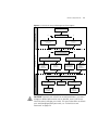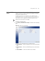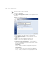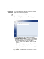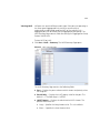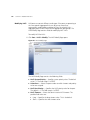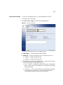
1
3Com® Baseline Switch 2924-PWR Plus
User Guide
3CBLSG24PWR
www.3Com.com
Part Number 10016095 Rev. AA
Published June 2007
3Com Corporation
350 Campus Drive
Marlborough,
MA 01752-3064
Copyright © 2007, 3Com Corporation. All rights reserved. No part of this documentation may be reproduced
in any form or by any means or used to make any derivative work (such as translation, transformation, or
adaptation) without written permission from 3Com Corporation.
3Com Corporation reserves the right to revise this documentation and to make changes in content from time
to time without obligation on the part of 3Com Corporation to provide notification of such revision or change.
3Com Corporation provides this documentation without warranty, term, or condition of any kind, either
implied or expressed, including, but not limited to, the implied warranties, terms or conditions of
merchantability, satisfactory quality, and fitness for a particular purpose. 3Com may make improvements or
changes in the product(s) and/or the program(s) described in this documentation at any time.
If there is any software on removable media described in this documentation, it is furnished under a license
agreement included with the product as a separate document, in the hard copy documentation, or on the
removable media in a directory file named LICENSE.TXT or !LICENSE.TXT. If you are unable to locate a copy,
please contact 3Com and a copy will be provided to you.
UNITED STATES GOVERNMENT LEGEND
If you are a United States government agency, then this documentation and the software described herein are
provided to you subject to the following:
All technical data and computer software are commercial in nature and developed solely at private expense.
Software is delivered as “Commercial Computer Software” as defined in DFARS 252.227-7014 (June 1995) or
as a “commercial item” as defined in FAR 2.101(a) and as such is provided with only such rights as are
provided in 3Com’s standard commercial license for the Software. Technical data is provided with limited
rights only as provided in DFAR 252.227-7015 (Nov 1995) or FAR 52.227-14 (June 1987), whichever is
applicable. You agree not to remove or deface any portion of any legend provided on any licensed program or
documentation contained in, or delivered to you in conjunction with, this User Guide.
Unless otherwise indicated, 3Com registered trademarks are registered in the United States and may or may not
be registered in other countries.
3Com and the 3Com logo are registered trademarks of 3Com Corporation.
Intel and Pentium are registered trademarks of Intel Corporation. Microsoft, MS-DOS, Windows, and Windows
NT are registered trademarks of Microsoft Corporation. Novell and NetWare are registered trademarks of
Novell, Inc. UNIX is a registered trademark in the United States and other countries, licensed exclusively
through X/Open Company, Ltd.
IEEE and 802 are registered trademarks of the Institute of Electrical and Electronics Engineers, Inc.
All other company and product names may be trademarks of the respective companies with which they are
associated.
ENVIRONMENTAL STATEMENT
It is the policy of 3Com Corporation to be environmentally friendly in all operations. To uphold our policy, we
are committed to:
Establishing environmental performance standards that comply with national legislation and regulations.
Conserving energy, materials and natural resources in all operations.
Reducing the waste generated by all operations. Ensuring that all waste conforms to recognized
environmental standards. Maximizing the recyclable and reusable content of all products.
Ensuring that all products can be recycled, reused and disposed of safely.
Ensuring that all products are labelled according to recognized environmental standards.
Improving our environmental record on a continual basis.
End of Life Statement
3Com processes allow for the recovery, reclamation and safe disposal of all end-of-life electronic components.
Regulated Materials Statement
3Com products do not contain any hazardous or ozone-depleting material.
Environmental Statement about the Documentation
The documentation for this product is printed on paper that comes from sustainable, managed forests; it is
fully biodegradable and recyclable, and is completely chlorine-free. The varnish is environmentally friendly, and
the inks are vegetable-based with a low heavy-metal content.
ABOUT THIS GUIDE
This guide provides information about the Web user interface for the
3Com® Baseline Switch 2924-PWR Plus. The Web interface is a network
management system that allows you to configure, monitor, and
troubleshoot your switch from a remote web browser. The Web interface
web pages are easy-to-use and easy-to-navigate.
User Guide
Overview
This section provides an overview to the User Guide. The User Guide
provides the following sections:
■
Getting Started — Provides introductory information about the
Switch 2924-PWR and how it can be used in your network. It covers
summaries of hardware and software features.
■
Using the 3Com Web Interface — Provides information for using
the Web interface including adding, editing, and deleting device
configuration information.
■
Viewing Basic Settings — provides information for viewing and
configuring essential information required for setting up and
maintaining device settings.
■
Managing Device Security — Provides information for configuring
both system and network security, including traffic control, ACLs, and
device access methods.
■
Managing System Information — Provides information for
configuring general system information including the user-defined
system name, the user-defined system location, and the system
contact person.
■
Configuring Ports — Provides information for configuring port
settings.
■
Aggregating Ports — Provides information for configuring Link
Aggregation which optimizes port usage by linking a group of ports
together to form a single LAG.
4
ABOUT THIS GUIDE
■
Configuring VLANs — Provides information for configuring VLANs.
VLANs are logical subgroups with a Local Area Network (LAN) which
combine user stations and network devices into a single virtual LAN
segment, regardless of the physical LAN segment to which they are
attached.
■
Configuring IP and MAC Address Information — Provides
information for configuring IP addresses, DHCP and ARP.
■
Configuring IGMP Snooping — Provides information for
configuring IGMP Snooping.
■
Configuring Spanning Tree — Provides information for configuring
Classic and Rapid Spanning Tree.
■
Configuring SNMP — Provides information for configuring the
Simple Network Management Protocol (SNMP) which provides a
method for managing network devices.
■
Configuring Quality of Service — Provides information defining
Quality of Service, including DSCP and CoS mapping, policies, and
configuring Trust mode.
■
Managing System Files — Provides information for defining file
maintenance.
■
Managing Power over Ethernet Devices — Provides information
for configuring ports for PoE.
■
Managing System Logs — Provides information for viewing system
logs, and configuring device log servers.
■
Viewing Statistics — Provides information for viewing RMON and
interface statistics.
■
Managing Device Diagnostics — Provides information for
managing device diagnostics.
Intended Audience
Intended Audience
5
This guide is intended for network administrators familiar with IT
concepts and terminology.
If release notes are shipped with your product and the information there
differs from the information in this guide, follow the instructions in the
release notes.
Most user guides and release notes are available in Adobe Acrobat
Reader Portable Document Format (PDF) or HTML on the 3Com Web site:
■
Conventions
http://www.3Com.com
Table 1 lists conventions that are used throughout this guide.
Table 1 Notice Icons
Icon
Related
Documentation
Notice Type
Description
Information
note
Information that describes important features or
instructions.
Caution
Information that alerts you to potential loss of data
or potential damage to an application, system, or
device.
Warning
Information that alerts you to potential personal
injury.
In addition to this guide, other documentation available for the 3Com®
Baseline Switch 2924-PWR Plus include the following:
■
Safety and Support Information: Provides installation, set-up, and
regulatory compliance information.
CONTENTS
ABOUT THIS GUIDE
User Guide Overview ................................................................................. 3
Intended Audience..................................................................................... 5
Conventions .............................................................................................. 5
Related Documentation ............................................................................. 5
1
GETTING STARTED
About the Switch 2924-PWR ................................................................... 14
Summary of Hardware Features ..................................................... 14
Front Panel Detail..................................................................................... 15
LED Status Indicators................................................................................ 16
System Specifications ............................................................................... 17
Installing the Switch................................................................................. 18
Setting Up for Management .................................................................... 19
Methods of Managing a Switch ............................................................... 19
Web Interface Management .......................................................... 19
SNMP Management ....................................................................... 20
Switch Setup Overview ............................................................................ 20
IP Configuration ............................................................................ 22
Using the Command Line Interface (CLI) .................................................. 23
Connecting to the Console Port ..................................................... 23
Manually set the IP Address using the Console Port ....................... 24
Viewing IP Information using the Console Port ............................... 25
Setting Up Web Interface Management ................................................... 27
Web Management Over the Network ............................................ 28
Setting Up SNMP Management V1 or V2 ................................................. 28
Default Users and Passwords.................................................................... 29
Upgrading Software using the CLI............................................................ 29
2
USING THE 3COM WEB INTERFACE
Starting the 3Com Web Interface .............................................................31
Multi-Session Web Connections ..................................................... 31
Accessing the 3Com Web Interface ................................................ 32
Understanding the 3Com Web Interface...................................................33
Device Representation .................................................................... 35
Using the 3Com Web Interface Management Buttons .................... 35
Using Screen and Table Options................................................................36
Saving the Configuration..........................................................................40
Resetting the Device.................................................................................41
Restoring Factory Defaults ........................................................................43
Logging Off the Device.............................................................................44
3
VIEWING BASIC SETTINGS
Viewing Device Settings ................................................................. 46
Viewing Color Keys ........................................................................ 48
4
MANAGING DEVICE SECURITY
Configuring System Access.......................................................................50
Viewing System Access Settings ..................................................... 51
Defining System Access .................................................................. 52
Modifying System Access ............................................................... 53
Removing System Access ................................................................ 54
Defining RADIUS Clients...........................................................................55
Defining Port-Based Authentication (802.1X)............................................57
Viewing 802.1X Authentication ..................................................... 58
Defining 802.1X Authentication ..................................................... 60
Defining Access Control Lists ....................................................................62
Viewing MAC Based ACLs .............................................................. 63
Configuring MAC Based ACLs ........................................................ 64
Modifying MAC Based ACLs .......................................................... 67
Removing MAC Based ACLs ........................................................... 69
Viewing IP Based ACLs ................................................................... 71
Defining IP Based ACLs .................................................................. 72
Modifying IP Based ACLs ................................................................ 77
Removing IP Based ACLs ................................................................ 80
Viewing ACL Binding ..................................................................... 83
Configuring ACL Binding ............................................................... 84
Removing ACL Binding .................................................................. 85
Enabling Broadcast Storm ........................................................................ 86
5
MANAGING SYSTEM INFORMATION
Viewing System Description ...........................................................
Defining System Settings ...............................................................
Configuring System Name .............................................................
Configuring System Time ...............................................................
Saving the Device Configuration ....................................................
Resetting the Device ......................................................................
6
89
91
92
93
96
97
CONFIGURING PORTS
Viewing Port Settings ..................................................................... 99
Defining Port Settings .................................................................. 102
Viewing Port Details ..................................................................... 104
7
AGGREGATING PORTS
Viewing Link Aggregation ............................................................
Configuring Link Aggregation ......................................................
Modifying Link Aggregation ........................................................
Removing Link Aggregation .........................................................
Viewing LACP ..............................................................................
Modifying LACP ...........................................................................
8
107
107
110
112
113
114
CONFIGURING VLANS
Viewing VLAN Details ..................................................................
Viewing VLAN Port Details ...........................................................
Creating VLANs ...........................................................................
Modifying VLAN Settings .............................................................
Modifying Port VLAN Settings ......................................................
Removing VLANs .........................................................................
117
118
119
121
123
124
9
CONFIGURING IP AND MAC ADDRESS INFORMATION
Defining IP Addressing ................................................................. 126
Configuring ARP Settings .......................................................................127
Viewing ARP Settings ................................................................... 128
Defining ARP Settings .................................................................. 129
Removing ARP Entries .................................................................. 130
Configuring Address Tables ....................................................................132
Viewing Address Table Settings .................................................... 133
Viewing Port Summary Settings .................................................... 134
Adding MAC Addresses to the Address Table ............................... 136
Defining Aging Time .................................................................... 138
Removing Address Table Ports ...................................................... 139
Removing MAC Addresses from the Address Table ....................... 141
10
CONFIGURING IGMP SNOOPING
Defining IGMP Snooping
11
.............................................................. 144
CONFIGURING SPANNING TREE
Viewing Spanning Tree ................................................................. 147
Defining Spanning Tree ................................................................ 150
Modifying Spanning Tree .............................................................. 153
12
CONFIGURING SNMP
Defining SNMP Communities .......................................................
Removing SNMP Communities .....................................................
Defining SNMP Traps ....................................................................
Removing SNMP Traps ..................................................................
13
156
158
159
160
CONFIGURING QUALITY OF SERVICE
Viewing CoS Settings ...................................................................
Defining CoS ................................................................................
Viewing CoS to Queue .................................................................
Defining CoS to Queue ................................................................
Viewing DSCP to Queue ...............................................................
Configuring DSCP Queue .............................................................
163
164
165
165
167
168
Configuring Trust Settings ........................................................... 169
Viewing Bandwidth Settings ........................................................ 170
Defining Bandwidth Settings ........................................................ 172
Defining Voice VLAN.............................................................................. 174
Viewing Voice VLANs ................................................................... 175
Defining Voice VLAN .................................................................... 176
Defining Voice VLAN Port Settings ............................................... 177
Viewing Voice VLAN Port Definitions ............................................ 179
Viewing the OUI Summaries ........................................................ 180
Modifying OUI Definitions ............................................................ 182
14
MANAGING SYSTEM FILES
Backing Up System Files ...............................................................
Restoring Files ..............................................................................
Restore the Software Image .........................................................
Activating Image Files ..................................................................
15
MANAGING POWER OVER ETHERNET DEVICES
Viewing PoE Settings
Defining PoE Settings
16
186
187
188
189
................................................................... 191
................................................................... 193
MANAGING SYSTEM LOGS
Viewing Logs ............................................................................... 196
Configuring Logging .................................................................... 197
17
VIEWING STATISTICS
Viewing Port Statistics
18
.................................................................. 201
MANAGING DEVICE DIAGNOSTICS
Configuring Port Mirroring..................................................................... 205
Defining Port Mirroring ................................................................ 206
Removing Port Mirroring .............................................................. 208
Viewing Cable Diagnostics ..................................................................... 209
Configuring Cable Diagnostics ..................................................... 210
A
3COM NETWORK MANAGEMENT
3Com Network Supervisor......................................................................212
3Com Network Director .........................................................................213
3Com Network Access Manager ............................................................213
3Com Enterprise Management Suite ......................................................214
Integration Kit with HP OpenView Network Node Manager ....................214
B
DEVICE SPECIFICATIONS AND FEATURES
Related Standards ..................................................................................215
Environmental ........................................................................................215
Physical ..................................................................................................215
Electrical.................................................................................................216
Switch Features ......................................................................................216
C
PIN-OUTS
Null Modem Cable .................................................................................221
PC-AT Serial Cable..................................................................................221
Modem Cable ........................................................................................222
Ethernet Port RJ-45 Pin Assignments ......................................................222
D
TROUBLESHOOTING
Problem Management ............................................................................224
Troubleshooting Solutions ......................................................................224
E
3COM CLI REFERENCE GUIDE
Getting Started with the Command Line Interface ..................................227
Console Port ................................................................................ 227
Logging on to the CLI .................................................................. 227
Automatic Logout ........................................................................ 228
Concurrent CLI Sessions ............................................................... 228
CLI Commands.......................................................................................228
? .................................................................................................. 229
Ping ............................................................................................. 230
Summary ..................................................................................... 231
ipSetup ........................................................................................ 232
Upgrade ......................................................................................
Initialize .......................................................................................
Reboot ........................................................................................
Logout .........................................................................................
Password .....................................................................................
F
233
234
235
236
237
GLOSSARY
............................................................................................................. 238
G
OBTAINING SUPPORT FOR YOUR 3COM PRODUCTS
Register Your Product to Gain Service Benefits ....................................... 244
Solve Problems Online............................................................................ 244
Purchase Extended Warranty and Professional Services........................... 244
Access Software Downloads .................................................................. 245
Contact Us............................................................................................. 245
Telephone Technical Support and Repair ...................................... 245
REGULATORY NOTICES
1
GETTING STARTED
This chapter contains introductory information about the 3Com® Baseline
Switch 2924-PWR Plus (hereafter called the Switch) and how they can be
used in your network. It covers summaries of hardware and software
features and also the following topics:
■
About the Switch 2924-PWR
■
Front Panel Detail
■
LED Status Indicators
■
System Specifications
■
Installing the Switch
■
Setting Up for Management
■
Methods of Managing a Switch
■
Switch Setup Overview
■
Using the Command Line Interface (CLI)
■
Setting Up Web Interface Management
■
Setting Up SNMP Management V1 or V2
■
Default Users and Passwords
■
Upgrading Software using the CLI
14
CHAPTER 1: GETTING STARTED
About the Switch
2924-PWR
The Switch 2924-PWR is a Gigabit Ethernet switching products that
delivers flexible three-speed performance (10/100/1000), Power over
Ethernet (PoE) and advanced voice-optimized features such as auto-QoS
and auto-voice VLAN. This makes the switch ideal for medium businesses
and small enterprises seeking to build a secure converged network.
The Switch 2924-PWR includes the following model:
■
Baseline Switch 2924-PWR Plus 24-Port
The Switch 2924-PWR features the following advantages:
Summary of
Hardware Features
■
Full Gigabit speed access ports
■
Jumbo frames support
■
Port security
■
Link aggregation control protocol (LACP)
■
Up to 256 VLANs
■
Access control lists (ACLs)
■
Port-based mirroring
Table 1 summarizes the hardware features supported by the Switch
2924-PWR.
Table 1 Hardware Features
Feature
Switch 2924-PWR
Addresses
Up to 8,000 supported
Auto-negotiation
Supported on all ports
Forwarding Modes
Store and Forward
Duplex Modes
Half and full duplex on all front panel ports
Auto MDI/MDIX
Supported on all ports. If fiber SFP transceivers are used,
Auto MDIX is not supported.
Flow Control
In full duplex operation all ports are supported.
The Switch 2924-PWR ports are capable of receiving,
but not sending pause frames.
Traffic Prioritization
Supported (using the IEEE Std 802.ID, 1998 Edition):
Four traffic queues per port
Front Panel Detail
15
Table 1 Hardware Features (continued)
Feature
Switch 2924-PWR
Ethernet, Fast Ethernet,
Auto-negotiating 10/100/1000BASE-T ports
and Gigabit Ethernet Ports
Front Panel Detail
SFP Ethernet Ports
Supports fiber Gigabit Ethernet long-wave (LX), and
fiber Gigabit Ethernet short-wave (SX) transceivers in
any combination.
Mounting
19-inch rack or standalone mounting
Figure 1 shows the front panel of the Switch 2924-PWR Plus 24-Port unit
Figure 1 Switch 2924-PWR Plus 24-Port—front panel.
1
13
4 5
16 17
8 9
20
12
24
22
24
21
23
16
CHAPTER 1: GETTING STARTED
LED Status
Indicators
The 2924-PWR SFP Plus 24-Port Ethernet switch provides LED indicators
on the front panel for your convenience to monitor the switch. Table 2
describes the meanings of the LEDs.
Table 2 Description on the LEDs of the Switch 2924-PWR
LED
Label
Status
Description
Power
Power
Green
The switch starts normally. The LED flashes
when the system is performing power-on self
test (POST).
Yellow
The system has failed the POST.
OFF
The switch is powered off.
Green
The port works at the rate of 1000 Mbps; the
LED flashes quickly when the port is sending
or receiving data.
Yellow
The port works at the rate of 10/100 Mbps;
the LED flashes quickly when the port is
sending or receiving data.
OFF
The port is not connected.
Yellow
The port is in full duplex mode.
OFF
The port is not connected, or is in half duplex
mode.
10/100/1000
BASE-T
Ethernet port
status
Duplex mode
Link/
Activity
Duplex
1000Base SFP
port status
SFP
Module
Active
Green
The SFP module is inserted.
OFF
The SFP module is not inserted or is not
recognized.
PoE status
PoE
Status
Green
Delivering power. The LED flashes if a fault
occurs.
OFF
Not delivering power.
System Specifications
System
Specifications
Table 3 contains the system specifications of the 2924-PWR series
switch.
Table 3 System specifications of the Switch 2924PWR series switch
Specification
Switch 2924-PWR Plus 24-Port 3CBLSG24PWR
Physical dimensions
(H×W×D)
44×440×265 mm (1.73 17.3 10.43 in.)
Weight
3.6 kg (7.9 lb)
Console port
One Console port
Gigabit Ethernet ports on
the front panel
24 × 10/100/1000 Mbps Ethernet ports
AC Input voltage
Rated voltage range: 100–240 VAC, 50/60 Hz
Power consumption
(full load)
350 W
Operating temperature
0 to 40 °C (32 to 113 °F)
Relative humidity
10 to 90% noncondensing
Four Gigabit SFP Combo ports
Additional specifications can be found in Appendix B “Device
Specifications and Features”.
17
18
CHAPTER 1: GETTING STARTED
Installing the
Switch
This section contains information that you need to install and set up your
3Com switch.
WARNING: Safety Information. Before you install or remove any
components from the Switch or carry out any maintenance procedures,
you must read the 3Com Switch Family Safety and Regulatory
Information document enclosed.
AVERTISSEMENT: Consignes de securite. Avant d'installer ou d'enlever
tout composant de Switch ou d'entamer une procedure de maintenance,
lisez les informations relatives a la securite qui se trouvent dans 3Com
Switch Family Safety and Regulatory Information.
VORSICHT: Sicherheitsinformationen. Bevor Sie Komponenten aus
dem Switch entfernen oder den Switch hinzufugen oder
Instandhaltungsarbeiten verrichten, lesen Sie die 3Com Switch Family
Safety and Regulatory Information.
ADVERTENCIA: Informacion de seguridad. Antes de instalar o extraer
cualquier componente del Switch o de realizar tareas de mantenimiento,
debe leer la informacion de seguridad facilitada en el 3Com Switch Family
Safety and Regulatory Information.
AVVERTENZA: Informazioni di sicurezza. Prima di installare o
rimuovere qualsiasi componente dal Switch o di eseguire qualsiasi
procedura di manutenzione, leggere le informazioni di sicurezza riportate
3Com Switch Family Safety and Regulatory Information.
OSTRZEŻENIE: Informacje o zabezpieczeniach. Przed instalacją
lub usunięciem jakichkolwiek elementów z product lub
przeprowadzeniem prac konserwacyjnych należy zapoznać się z
informacjami o bezpieczeństwie zawartymi w 3Com Switch Family
Safety and Regulatory Information.
CAUTION Opening the switch or tampering with the warranty sticker
can void your warranty.
Setting Up for Management
Setting Up for
Management
19
To make full use of the features offered by your switch, and to change
and monitor the way it works, you have to access the management
software that resides on the switch. This is known as managing the
switch. Managing the switch can help you to improve the efficiency of
the switch and therefore the overall performance of your network.
This section explains the initial set up of the switch and the different
methods of accessing the management software to manage a switch. It
covers the following topics:
Methods of
Managing a Switch
■
Methods of Managing a Switch
■
Switch Setup Overview
■
Manually set the IP Address using the Console Port
■
Viewing IP Information using the Console Port
■
Setting Up Web Interface Management
■
Setting Up SNMP Management V1 or V2
■
Default Users and Passwords
To manage your switch you can use one of the following methods:
■
Web Interface Management
■
SNMP Management
In addition, you can use the Command Line Interface through the
Console port for basic operations of the switch including setting and
viewing the IP address, configuring user accounts, upgrading switch
firmware, and more. Refer to “3Com CLI Reference Guide” on page 227.
Web Interface
Management
Each switch has an internal set of web pages that allow you to manage
the switch using a Web browser remotely over an IP network (see
Figure 2).
20
CHAPTER 1: GETTING STARTED
Figure 2 Web Interface Management over the Network
Switch
Workstation
Connect over Network
via web browser
Refer to “Setting Up Web Interface Management” on page 27.
SNMP Management
You can manage a switch using any network management workstation
running the Simple Network Management Protocol (SNMP) as shown in
Figure 3. For example, you can use the 3Com Network Director software,
available from the 3Com website.
Figure 3 SNMP Management over the Network
SNMP Network Management
Workstation
Switch
Connect over Network
using SNMP
Refer to “Setting Up SNMP Management V1 or V2” on page 28.
Switch Setup
Overview
This section gives an overview of what you need to do to get your switch
set up and ready for management when it is in its default state. The
whole setup process is summarized in Figure 4. Detailed procedural steps
are contained in the sections that follow. In brief, you need to:
■
Configure IP information manually for your switch or view the
automatically configured IP information
■
Prepare for your chosen method of management
Switch Setup Overview
21
Figure 4 Initial Switch Setup and Management Flow Diagram
Plug and Play Setup
Power Up the Switch.
Is a DHCP server present?
Yes
IP Information is automatically
configured using DHCP
See page 22
The switch uses its default IP
information
See page 22
Do you want to manually
configure the IP information?
Yes
Initial IP Information Setup
No
How do you want to view the automatically
configured IP information?
How do you want to connect to the Switch?
Connect to the
console port and use
the Command Line
Interface.
See page 23
No
Connect to a front panel
port and use the Web
Interface.
See page 27
Refer to the label on
the rear of the switch
which details the
default IP address.
Connect to the
console port and use
the Command Line
Interface.
See page 25
Feature Management
How do you want to manage your Switch? See page 19
Command Line Interface
(basic setup only)
Connect using the
console port.
See page 23
SNMP
See page 28
Web Interface
Connect over the
network.
See page 28
CAUTION To protect your switch from unauthorized access, you must
change the default password as soon as possible, even if you do not
intend to actively manage your switch. For more information on default
users and changing default passwords, see “Default Users and
Passwords” on page 29.
22
CHAPTER 1: GETTING STARTED
IP Configuration
The switch’s IP configuration is determined automatically using DHCP, or
manually using values you assign.
Automatic IP Configuration using DHCP
By default the switch tries to configure its IP Information without
requesting user intervention. It tries to obtain an IP address from a DHCP
server on the network.
Default IP Address If no DHCP server is detected, the switch will use
its default IP information. The default IP address is 169.254.x.y, where x
and y are the last two bytes of its MAC address.
Note: The switch’s default IP address is listed on a label located on the
rear of the switch.
If you use automatic IP configuration it is important that the IP address of
the switch is static, otherwise the DHCP server can change the switch’s IP
addresses and it will be difficult to manage. Most DHCP servers allow
static IP addresses to be configured so that you know what IP address will
be allocated to the switch. Refer to the documentation that accompanies
your DHCP server.
You should use the automatic IP configuration method if:
■
your network uses DHCP to allocate IP information, or
■
flexibility is needed. If the switch is deployed onto a different subnet, it
will automatically reconfigure itself with an appropriate IP address,
instead of you having to manually reconfigure the switch.
If you use the automatic IP configuration method, you need to discover
the automatically allocated IP information before you can begin
management. Work through the “Viewing IP Information using the
Console Port” on page 25.
Manual IP Configuration
When you configure the IP information manually, the switch remembers
the information that you enter until you change it again.
You should use the Manual IP configuration method if:
■
You do not have a DHCP server on your network, or
■
You want to remove the risk of the IP address ever changing, or
Using the Command Line Interface (CLI)
■
23
Your DHCP server does not allow you to allocate static IP addresses.
(Static IP addresses are necessary to ensure that the switch is always
allocated the same IP information.)
For most installations, 3Com recommends that you configure the switch
IP information manually. This makes management simpler and more
reliable as it is not dependent on a DHCP server, and eliminates the risk of
the IP address changing.
To manually enter IP information for your switch, work through the
“Manually set the IP Address using the Console Port” on page 24.
Using the
Command Line
Interface (CLI)
You can access the switch through the Console port to manually set the
IP address, or to view the IP address that was assigned automatically (for
example, by a DHCP server).
For more information about the CLI, refer to “3Com CLI Reference Guide”
on page 227.
Connecting to the
Console Port
This section describes how to connect to your switch through the
Console port.
Prerequisites
■
A workstation with terminal emulation software installed, such as
Microsoft Hyperterminal. This software allows you to communicate
with the switch using the console port directly.
■
Documentation supplied with the terminal emulation software.
■
The console cable (RJ-45) supplied with your switch.
You can find pin-out diagrams for the cable in Appendix C on page 221.
24
CHAPTER 1: GETTING STARTED
Connecting the Workstation to the Switch
1 Connect the workstation to the console port using the console cable as
shown in Figure 5.
Figure 5 Connecting a Workstation to the Switch using the Console Port
Workstation
(with terminal emulation
software installed)
Switch
Console Port
Connection
Console Cable
To connect the cable:
a Attach the cable’s RJ-45 connector to the Console port of the switch.
b Attach the other end of the cable to the workstation.
2 Open your terminal emulation software and configure the COM port
settings to which you have connected the cable. The settings must be set
to match the default settings for the switch, which are:
■
38,400 baud (bits per second)
■
8 data bits
■
no parity
■
1 stop bit
■
no hardware flow control
Refer to the documentation that accompanies the terminal emulation
software for more information.
3 Power up the switch. The Power on Self Test (POST) will be performed.
The Switch 2924-PWR takes approximately one minute to boot.
Manually set the IP
Address using the
Console Port
You are now ready to manually set up the switch with IP information
using the command line interface.
■
You need to have the following information:
■
IP address
■
subnet mask
■
default gateway
Using the Command Line Interface (CLI)
25
1 Connect to the switch Console port as described in “Connecting to the
Console Port” page 23.
2 The command line interface login sequence begins as soon as the switch
detects a connection to its console port. When the process completes,
the Login prompt displays.
3 At the login prompt, enter admin as your user name and press Return.
The Password prompt displays.
4 Press Return. If you have logged on correctly, Select menu option#
should be displayed.
5 Enter the IP address and subnet mask for the switch as follows:
ipSetup xxx.xxx.xxx.xxx mmm.mmm.mmm.mmm ggg.ggg.ggg.gggg
and press Enter.
(Note: xxx.xxx.xxx.xxx is the IP address, mmm.mmm.mmm.mmm is the
subnet mask, and ggg.ggg.ggg.ggg is the default gateway of the switch.)
6 Enter the logout command to terminate the CLI session.
The initial setup of your switch is now complete and the switch is ready
for you to set up your chosen management method. See “Methods of
Managing a Switch” on page 19.
Viewing IP
Information using the
Console Port
This section describes how to view the automatically allocated IP
information using the command line interface. The automatic IP
configuration process usually completes within one minute after the
switch is connected to the network and powered up.
1 Connect to the switch Console port as described in “Connecting to the
Console Port” page 23.
The automatic IP configuration process usually completes within one
minute.
2 The command line interface login sequence begins as soon as the switch
detects a connection to its console port.
3 At the login prompt, enter admin as your user name and press Return.
4 At the password prompt, press Return.If you have logged on correctly,
Select menu option# is displayed.
26
CHAPTER 1: GETTING STARTED
5 Enter Summary to view a summary of allocated IP addresses. The
following is an example of the display from the Summary command.
Select menu option# summary
IP Method:
default
IP address:
169.254.99.51
Subnet mask:
255.255.0.0
Runtime version:
00_00_38 (date 01-Apr-2007 time 15:31:29)
Bootcode version: 1.0.0.12 (date 01-Apr-2007 time 17:44:52)
Select menu option#
The initial set up of your switch is now complete and the switch is ready
for you to set up your chosen management method. See “Methods of
Managing a Switch” on page 19.
For more information about the CLI, refer to “3Com CLI Reference Guide”
on page 227.
If you do not intend to use the command line interface using the console
port to manage the switch, you can logout, disconnect the serial cable
and close the terminal emulator software.
Setting Up Web Interface Management
Setting Up Web
Interface
Management
27
This section describes how you can set up web interface management
over the network.
Prerequisites
■
Ensure you have already set up the switch with IP information as
described in “Methods of Managing a Switch” on page 19.
■
Ensure that the switch is connected to the network using a Category 5
twisted pair Ethernet cable with RJ-45 connectors.
■
A suitable Web browser.
Choosing a Browser
To display the web interface correctly, use one of the following Web
browser and platform combinations:
Table 4 Supported Web Browsers and Platforms
Platform
Browser
Windows 2000
Windows XP
Windows Vista
Internet Explorer 6
Yes
Yes
Yes
Internet Explorer 7
Yes
Yes
Yes
Firefox 1.5
Yes
Yes
Yes
Firefox 2
Yes
Yes
Yes
Netscape 8
Yes
Yes
Yes
For the browser to operate the web interface correctly, JavaScript and
Cascading Style Sheets must be enabled on your browser. These features
are enabled on a browser by default. You will only need to enable them if
you have changed your browser settings.
The switch’s Web interface supports both secure (HTTPS) and non-secure
(HTTP) connections.
28
CHAPTER 1: GETTING STARTED
Web Management
Over the Network
To manage a switch using the web interface over an IP network:
1 Be sure that you know your switch’s IP address. See “IP Configuration”
on page 22, and “Viewing IP Information using the Console Port” on
page 25.
2 Check that your management workstation is on the same subnet as your
switch.
3 Check you can communicate with the switch by entering a ping
command at the DOS or CMD prompt in the following format:
c:\ ping xxx.xxx.xxx.xxx
(where xxx.xxx.xxx.xxx is the IP address of the switch)
If you get an error message, check that your IP information has been
entered correctly and the switch is powered up.
4 Open your web browser and enter the IP address of the switch that you
wish to manage in the URL locator, for example, in the following format:
http://xxx.xxx.xxx.xxx
5 At the login and password prompts, enter admin as your user name and
press Return at the password prompt (or the password of your choice if
you have already modified the default passwords).
The main Web interface page is displayed.
Setting Up SNMP
Management V1 or
V2
You can use any network management application running the Simple
Network Management Protocol (SNMP) to manage the switch. 3Com
offers a range of network management applications to address networks
of all sizes and complexity. See “3Com Network Management” on
page 212.
Be sure the management workstation is connected to the switch using a
port in VLAN 1 (the Default VLAN). By default, all ports on the switch are
in VLAN 1.
To display and configure SNMP management parameters, refer to
“Configuring SNMP” on page 155.
Default Users and Passwords
Default Users and
Passwords
29
If you intend to manage the switch or to change the default passwords,
you must log in with a valid user name and password. The switch has one
default user name. The default user is listed in Table 5.
Table 5 Default Users
Default
User Name Password
admin
(no password)
Access Level
Management — The user can access and change
all manageable parameters
Use the admin default user name (no password) to login and carry out
initial switch setup.
Upgrading
Software using the
CLI
This section describes how to upgrade software to your Switch from the
Command Line Interface (CLI).
Note: You can also upgrade the software using the switch Web user
interface. See “Restore the Software Image” page 188. Bootcode can
only be upgraded using the CLI.
1 To download the runtime application file, enter:
upgrade aaa.aaa.aaa.aaa rrr runtime
where aaa.aaa.aaa.aaa is the IP address of the TFTP server and rrr is the
source runtime filename.
2 To download the bootcode file, enter:
upgrade aaa.aaa.aaa.aaa bbb bootcode
where aaa.aaa.aaa.aaa is the IP address of the TFTP server and bbb is the
source bootcode filename.
The bootcode firmware may not require upgrading for every software
upgrade, therefore there may not be a new bootcode file to download.
3 To set the switch to boot from the new software you have downloaded,
enter the following:
reboot
The following prompt displays:
Are you sure you want to reboot the system (yes, no):
4 Enter yes and press Return. The system reboots the switch.
2
USING THE 3COM WEB INTERFACE
This section provides an introduction to the user interface, and includes
the following topics:
■
Starting the 3Com Web Interface
■
Understanding the 3Com Web Interface
■
Saving the Configuration
■
Resetting the Device
■
Restoring Factory Defaults
■
Logging Off the Device
Starting the 3Com Web Interface
Starting the 3Com
Web Interface
Multi-Session Web
Connections
31
This section includes the following topics:
■
Multi-Session Web Connections
■
Accessing the 3Com Web Interface
The Multi-Session web connections feature enables 10 users to be
created and access the switch concurrently. Access levels provide read or
read/write permissions to users for configuring the switch. Users and
access levels are described in Configuring System Access. Login
information is always handled in the local database. A unique password is
required of each user. Two access levels exist on the 3Com Web Interface:
■
Management access level — Provides the user with read/write
access. There is always one management level user configured for the
switch. The factory default is be username: admin with no Password.
■
Monitor access level — Provides the user with read-only access.
32
CHAPTER 2: USING THE 3COM WEB INTERFACE
Accessing the 3Com
Web Interface
This section contains information on starting the 3Com Web interface.
To access the 3Com user interface:
1 Open an Internet browser.
2 Enter the device IP address in the address bar and press Enter. The Enter
Network Password Page opens:
Figure 6 Enter Network Password Page
3 Enter your user name and password. The device default factory settings is
configured with a User Name that is admin and a password that is blank.
Passwords are case sensitive.
4 Click
. The 3Com Web Interface Home Page opens:
Understanding the 3Com Web Interface
33
Figure 7 3Com Web Interface Home Page
Understanding the
3Com Web
Interface
The 3Com Web Interface Home Page contains the following views:
■
Tab View — Provides the device summary configuration located at
the top of the home page.
■
Tree View — Provides easy navigation through the configurable
device features. The main branches expand to display the
sub-features.
■
Port Indicators — Located under the Device View at the top of the
home page, the port indicators provide a visual representation of the
ports on the front panel.
34
CHAPTER 2: USING THE 3COM WEB INTERFACE
Figure 8
Web Interface Components
The following table lists the user interface components with their
corresponding numbers:
Table 6:
Interface Components
Vi ew
Des cription
1 Tree View
Tree View provides easy navigation through the configurable
device features. The main branches expand to display the
sub-features.
2 Tab View
The Tab Area enables navigation through the different device
features. Click the tabs to view all the components under a specific feature.
3 Web Interface Information
Provides access to online help, and contains information about
the Web Interface.
This section provides the following additional information:
■
Device Representation — Provides an explanation of the user
interface buttons, including both management buttons and task
icons.
■
Using the 3Com Web Interface Management Buttons — Provides
instructions for adding, modifying, and deleting configuration
parameters.
Understanding the 3Com Web Interface
Device
Representation
35
The 3Com Web Interface Home Page contains a graphical panel
representation of the device that appears within the Device View Tab.
To access the Device Representation:
1 Click Device Summary > Device View.
Figure 9 Device Representation
2 By selecting a specific port with your mouse, you can view the port
statistics.
For detailed information on configuring ports, please refer to Configuring
Ports.
Using the 3Com Web
Interface
Management Buttons
Configuration Management buttons and icons provide an easy method
of configuring device information, and include the following:
Table 7:
Button
Table 8:
Ta b
3Com Web Interface Configuration Buttons
Button Name
Des cription
Clear Logs
Clears system logs.
Create
Creates configuration
entries.
Apply
Applies configuration
changes to the device.
Delete
Deletes configuration settings.
3Com Web Interface Information Tabs
Ta b Name
D escr ip tio n
Help
Opens the online help.
Logout
Logs the user out and
terminates the current
session.
36
CHAPTER 2: USING THE 3COM WEB INTERFACE
Using Screen and
Table Options
The 3Com Web interface contains screens and tables for configuring
devices. This section contains the following topics:
■
Viewing Configuration Information
■
Adding Configuration Information
■
Modifying Configuration Information
■
Removing Configuration Information
Viewing Configuration Information
To view configuration information:
1 Click Port > Administration > Summary. The Port Settings Summary
Page opens:
Figure 10 Port Settings Summary Page
Using Screen and Table Options
37
Adding Configuration Information
User-defined information can be added to specific 3Com Web Interface
pages, by opening the IP Setup Page.
To configure IP Setup:
1 Click Administration > IP Setup. The IP Setup Page opens:
Figure 11 IP Setup Page
2 Enter requisite information in the text field.
3 Click
updated.
. The IP information is configured, and the device is
38
CHAPTER 2: USING THE 3COM WEB INTERFACE
Modifying Configuration Information
1 Click Administration > System Access > Modify. The System Access
Modify Page opens:
Figure 12 System Access Modify Page
2 Modify the fields.
3 Click
. The access fields are modified.
Using Screen and Table Options
39
Removing Configuration Information
1 Click Administration > System Access > Remove. The System Access
Remove Page opens:
Figure 13 System Access Remove Page
2 Select the user account to be deleted.
3 Click
. The user account is deleted, and the device is updated.
40
CHAPTER 2: USING THE 3COM WEB INTERFACE
Saving the
Configuration
Configuration changes are only saved to the device once the user saves
the changes to the flash memory. The Save Configuration tab allows the
latest configuration to be saved to the flash memory.
To save the device configuration:
1 Click Save Configuration. The Save Configuration Page opens:
Figure 14 Save Configuration Page
A message appears: The operation will save your configuration. Do you
wish to continue?
2 Click
. A Configuration is saved to flash memory successful
message appears.
3 Click
. The configuration is saved.
Resetting the Device
Resetting the
Device
41
The Reset Page enables resetting the device from a remote location.
To prevent the current configuration from being lost, use the Save
Configuration Page to save all user-defined changes to the flash memory
before resetting the device.
To reset the device:
1 Click Administration > Reset. The Reset Page opens:
Figure 15 Reset Page
2 Click
. A confirmation message is displayed.
42
CHAPTER 2: USING THE 3COM WEB INTERFACE
3 Click
. The device is reset, and a prompt for a user name and
password is displayed.
Figure 16 User Name and Password Page
4 Enter a user name and password to reconnect to the web interface.
Restoring Factory Defaults
Restoring Factory
Defaults
The Restore option appears on the Reset Page. The Restore option
restores device factory defaults.
To restore the device:
1 Click Administration > Reset. The Reset Page opens:
Figure 17 Reset Page
The Reset Page contains the following fields:
■
■
2 Click
Initialize with Current IP Address — Resets the device with the
factory default settings, but maintains the current IP Address.
Initialize with Default IP Address — Resets the device with the
factory default settings, including the IP Address.
. The system is restored to factory defaults.
43
44
CHAPTER 2: USING THE 3COM WEB INTERFACE
Logging Off the
Device
To log off the device:
1 Click
. The Logout Page opens.
2 The following message appears:
3 Click
. The 3Com Web Interface Home Page closes.
3
VIEWING BASIC SETTINGS
This section contains information for viewing basic settings. The 3Com
Web Interface Home Page presents a device summary section that
provides the system administrator with the option to view essential
information required for setting up and maintaining device settings.
The Device Summary Section contains the following views:
■
Viewing Device Settings
■
Viewing Color Keys
46
CHAPTER 3: VIEWING BASIC SETTINGS
Viewing Device
Settings
The Device Summary Page displays parameters for viewing general device
information, including the system name, location, and contact, the
system MAC Address, System Object ID, System Up Time, and MAC
addresses, and both software, boot, and hardware versions.
To view the Device Summary Settings:
1 Click Device Summary. The Device Summary Page opens:
Figure 18 Device Summary Page
The Device Summary Page contains the following fields:
■
Product Description — Displays the device model number and name
■
System Name — Defines the user-defined device name. The field
length is 0-160 characters.
■
System Location — Defines the location where the system is
currently running. The field range is 0-160 characters.
■
System Contact — Defines the name of the contact person. The field
length is 0-160 characters.
■
Serial Number — Displays the device serial number.
■
Product 3C Number — Displays the 3Com device 3C number.
47
■
System Object ID — Displays the vendor’s authoritative identification
of the network management subsystem contained in the entity.
■
MAC Address — Displays the device MAC address.
■
System Up Time — Displays the amount of time since the most
recent device reset. The system time is displayed in the following
format: Days, Hours, Minutes, and Seconds. For example, 41 days, 2
hours, 22 minutes and 15 seconds.
■
Software Version — Displays the installed software version number.
■
Boot Version — Displays the current boot version running on the
device.
■
Hardware Version — Displays the current hardware version of the
device.
■
Poll Now — Enables polling the ports for port information including
speed, utilization and port status.
48
CHAPTER 3: VIEWING BASIC SETTINGS
Viewing Color Keys
The Color Key Page provides information regarding the RJ45 or SFP port
status on the device. The various colors key indicate the port status,
speed and link of a selected port.
To view color keys:
1 Click Device Summary > Color Key. The Color Key Page opens:
Figure 19 Color Key Page
The Color Key Page contains the following fields:
■
RJ45 — Displays the port status of the Registered Jack 45 (RJ45)
connections which are the physical interface used for terminating
twisted pair type cable.
■
SFP — Displays the port status of the Small Form Factor (SFP) optical
transmitter modules that combine transmitter and receiver functions.
The table includes the color and the port status:
■
White — Unconnected. No link detected.
■
Yellow — Lower speed on 10/100/1000M port.
■
Green — Maximum speed 10/100/1000M RJ45 or RJ45
SFP. Indicates that a link was detected.
■
Light Blue — SX/LX SFP. Indicates that a link was detected.
■
Light Gray — Port has been set to inactive by User or
Protocol.
■
Dark Blue — Port has been selected by user.
■
Red — Port or Transceiver has failed POST or Transceivers not
recognized.
4
MANAGING DEVICE SECURITY
The Management Security section provides information for configuring
system access, defining RADIUS authentication, port-based
authentication and defining access control lists.
This section includes the following topics:
■
Configuring System Access
■
Defining RADIUS Clients
■
Defining Port-Based Authentication (802.1X)
■
Defining Access Control Lists
■
Enabling Broadcast Storm
50
CHAPTER 4: MANAGING DEVICE SECURITY
Configuring System
Access
Network administrators can define users, passwords, and access levels for
users using the System Access Interface. The Multi-Session web feature is
enabled on device and allows 10 users to be created and access the
switch concurrently. Access levels provide read or read/write permissions
to users for configuring the switch. Login information is managed in the
local database. A unique password is required of each user. Two access
levels exist on the 3Com Web Interface:
■
Management access level — Provides the user with read/write
access. There is always one management level user configured for the
switch. The factory default user name is: admin with no password.
■
Monitor access level — Provides the user with read-only system
access.
This section contains the following topics:
■
Viewing System Access Settings
■
Defining System Access
■
Modifying System Access
■
Removing System Access
Configuring System Access
Viewing System
Access Settings
51
The System Access Summary Page displays the current users and access
levels defined on the device.
To view System Access settings:
1 Click Administration > System Access > Summary. The System Access
Summary Page opens:
Figure 20 System Access Summary Page
The System Access Summary Page contains the following fields:
■
User Name — Displays the user name. The possible predefined field
value is:
■
■
Admin — Displays the predefined administrative user name.
Access Level — Displays the user access level. The lowest user access
level is Monitor and the highest is Management.
■
■
Management — Provides the user with read and write access
rights.
Monitor — Provides the user with read access rights.
52
CHAPTER 4: MANAGING DEVICE SECURITY
Defining System
Access
The System Access Setup Page allows network administrators to define
users, passwords, and access levels for users using the System Access
Interface.
Monitor users have no access to this page.
To define System Access:
1 Click Administration > System Access > Setup. The System Access
Setup Page opens:
Figure 21 System Access Setup Page
The System Access Setup Page contains the following fields:
User Name — Defines the user name.
■
Access Level — Defines the user access level. The lowest user access
level is Monitor and the highest is Management.
■
Management — Provides users with read and write access rights.
■
Monitor — Provides users with read access rights.
■
Password — Defines the user password. User passwords can contain
up to 10 characters.
■
Confirm Password — Verifies the password.
2 Define the fields.
3 Click
. The user is created, and the device is updated.
■
Configuring System Access
Modifying System
Access
53
The System Access Modify Page allows network administrators to modify
users, passwords, and access levels for users using the System Access
Interface.
Monitor users have no access to this page.
To modify System Access:
1 Click Administration > System Access > Modify. The System Access
Modify Page opens:
Figure 22 System Access Modify Page
The System Access Modify Page contains the following fields:
User Name — Displays the user name.
■
Access Level — Specifies the user access level. The lowest user access
level is Monitoring and the highest is Management.
■
Management — Provides users with read and write access rights.
■
Monitor — Provides users with read access rights.
■
Password Modify — Enables modifying a password for an existing
user.
■
Password — Defines the local user password. Local user passwords
can contain up to 10 characters.
■
Confirm Password — Verifies the password.
2 Select a User Name whose settings are to be modified.
3 Modify the fields.
4 Click
. The user settings are modified, and the device is updated.
■
54
CHAPTER 4: MANAGING DEVICE SECURITY
Removing System
Access
The System Access Remove Page allows network administrators to
remove users from the System Access Interface.
Monitor users have no access to this page.
To remove users:
1 Click Administration > System Access > Remove. The System Access
Remove Page opens:
Figure 23 System Access Remove Page
The System Access Remove Page contains the following fields:
Remove User(s) — Users to be removed can be selected from the list
below.
■
User Name — Displays the user name.
■
Access Level — Displays the user access level. The lowest user access
level is Monitoring and the highest is Management.
■
Management — Provides users with read and write access rights.
■
Monitoring — Provides users with read access rights.
2 Select the Users to be deleted.
The last user with management access may not be deleted.
3 Click
. The Users are deleted, and the device is updated.
Defining RADIUS Clients
Defining RADIUS
Clients
55
Remote Authorization Dial-In User Service (RADIUS) servers provide
additional security for networks. RADIUS servers provide a centralized
authentication method for 802.1X.
The default parameters are user-defined, and are applied to newly
defined RADIUS servers. If new default parameters are not defined, the
system default values are applied to newly defined RADIUS servers.
Monitor users have no access to this page.
To configure the RADIUS client:
1 Click Security > RADIUS Client > Setup. The Radius Client Setup Page
opens:
Figure 24 Radius Client Setup Page
The Radius Client Setup Page contains the following fields:
■
Primary Server — Defines the RADIUS Primary Server authentication
fields.
■
Backup Server — Defines the RADIUS Backup Server authentication
fields.
■
Host IP Address — Defines the RADIUS Server IP address.
56
CHAPTER 4: MANAGING DEVICE SECURITY
■
Authentication Port — Defines the authentication port. The
authentication port is used to verify the RADIUS server authentication.
The authentication port default is 1812.
■
Number of Retries — Defines the number of transmitted requests
sent to the RADIUS server before a failure occurs. Possible field values
are 1-10. The default value is 3.
■
Timeout for Reply — Defines the amount of time (in seconds) the
device waits for an answer from the RADIUS server before retrying the
query, or switching to the next server. Possible field values are 1-30.
The default value is 3.
■
Dead Time — Defines the default amount of time (in minutes) that a
RADIUS server is bypassed for service requests. The range is 0-2000.
The default value is 0.
■
Key String — Defines the default key string used for authenticating
and encrypting all RADIUS-communications between the device and
the RADIUS server. This key must match the RADIUS encryption.
2 Define the fields.
3 Click
. The RADIUS client is enabled, and the system is updated.
Defining Port-Based Authentication (802.1X)
Defining Port-Based
Authentication
(802.1X)
57
Port-based authentication authenticates users on a per-port basis via an
external server. Only authenticated and approved system users can
transmit and receive data. Ports are authenticated via the RADIUS server
using the Extensible Authentication Protocol (EAP). Port-based
authentication includes:
■
Authenticators — Specifies the device port which is authenticated
before permitting system access.
■
Supplicants — Specifies the host connected to the authenticated
port requesting to access the system services.
■
Authentication Server — Specifies the server that performs the
authentication on behalf of the authenticator, and indicates whether
the supplicant is authorized to access system services.
Port-based authentication creates two access states:
■
Controlled Access — Permits communication between the
supplicant and the system, if the supplicant is authorized.
■
Uncontrolled Access — Permits uncontrolled communication
regardless of the port state.
This section includes the following topics:
■
Viewing 802.1X Authentication
■
Defining 802.1X Authentication
58
CHAPTER 4: MANAGING DEVICE SECURITY
Viewing 802.1X
Authentication
The 802.1X Summary Page allows the network administrator to view
port-based authentication settings.
To view Port-based Authentication:
1 Click Security > 802.1X > Summary. The 802.1X Summary Page opens:
Figure 25 802.1X Summary Page
The 802.1X Summary Page contains the following fields:
■
Port — Displays a list of interfaces.
■
User Name — Displays the supplicant user name.
■
Admin Port Control — Displays the admin port authorization state.
■
■
■
ForceUnauthorized — Indicates that no client has access to the
port, even if it has 802.1X credentials and supports 802.1X
authorization, or the port control is Auto but a client has not been
authenticated via the port.
ForceAuthorized — Indicates that any client has full access to the
port, even if it does not have 802.1X credentials or support 802.1X
authorization.
Auto — Indicates that the port control is Auto and a single client
has been authenticated via the port.
Defining Port-Based Authentication (802.1X)
59
■
Current Port Control — Displays the current port authorization state.
■
Guest VLAN — Indicates whether an unauthorized port is allowed to
join the Guest VLAN. The possible field values are:
■
■
Enable — Enables an unauthorized port to join the Guest VLAN.
■
Disable — Disables an unauthorized port to join the Guest VLAN.
Periodic Reauthentication — Indicates if periodic reauthentication is
enabled on the port.
■
■
Enable — Periodic reauthentication is enabled on the port.
Disable — Periodic reauthentication is disabled on the port. This is
the default.
■
Reauthentication Period — Displays the time span (in seconds) in
which the selected port is reauthenticated. The field default is 3600
seconds.
■
Authenticator State — Displays the current authenticator state.
■
Termination Cause — Indicates the reason for which the port
authentication was terminated.
60
CHAPTER 4: MANAGING DEVICE SECURITY
Defining 802.1X
Authentication
The 802.1X Setup Page contains information for configuring 802.1X
global settings on the device and defining specific 802.1X setting for
each port individually.
Monitor users have no access to this page.
To configure 802.1X Settings:
1 Click Security > 802.1X > Setup. The 802.1X Setup Page opens:
Figure 26 802.1X Setup Page
The 802.1X Setup Page contains the following fields:
802.1X Global Settings
■
Port Based Authentication State — Specifies if Port Authentication
is enabled on the device. The possible field values are:
■
Enable — Enables port-based authentication on the device.
■
Disable — Disables port-based authentication on the device. This is
the default value.
■
Authentication Method — Specifies the authentication method
used for port authentication. The possible field values are:
■
RADIUS — Provides port authentication using the RADIUS server.
■
RADIUS, None — Provides port authentication, first using the
RADIUS server. If the port is not authenticated, then no
authentication method is used, and the session is permitted.
■
None — Indicates that no authentication method is used to
authenticate the port.
Defining Port-Based Authentication (802.1X)
61
■
Enable Guest VLAN — Provides limited network access to authorized
ports. If a port is denied network access via port-based authorization,
but the Guest VLAN is enabled, the port receives limited network
access. For example, a network administrator can use Guest VLANs to
deny network access via port-based authentication, but grant Internet
access to unauthorized users.
■
Guest VLAN ID — Specifies the guest VLAN ID.
802.1X Port Settings
■
Admin Port Control — Specifies the admin port authorization state.
■
■
■
■
■
■
Force Authorized — Places the interface into an authorized state
without being authenticated. The interface re-sends and receives
normal traffic without client port based authentication.
Force Unauthorized — Denies the selected interface system access
by moving the interface into unauthorized state. The device cannot
provide authentication services to the client through the interface.
Guest VLAN — Specifies whether the Guest VLAN is enabled on the
port. The possible field values are:
■
■
Auto — Enables port based authentication on the device. The
interface moves between an authorized or unauthorized state
based on the authentication exchange between the device and the
client.
Enable — Enables using a Guest VLAN for unauthorized ports. If a
Guest VLAN is enabled, the unauthorized port automatically joins
the VLAN selected from the Guest VLAN ID dropdown list.
Disable — Disables Guest VLAN on the port. This is the default.
Periodic Reauthentication — Enables periodic reauthentication on
the port.
■
Enable — Enables the periodic reauthentication on the port.
■
Disable — Disables the periodic reauthentication on the port.
Reauthentication Period — Defines the time span (in seconds) in
which the selected port is reauthenticated. The field default is 3600
seconds.
2 Define the fields.
3 Click
. The 802.1X Settings are enabled, and the device is updated.
62
CHAPTER 4: MANAGING DEVICE SECURITY
Defining Access
Control Lists
Access Control Lists (ACLs) allow network managers to define
classification actions and rules for specific ingress ports. A network
manager can configure an ACL on an ingress port so that packets are
either admitted or denied entry. The user can also specify that when
packets are denied entry, the ingress port is also disabled.
For example, an ACL rule is defined stating that port number 20 can
receive TCP packets, however, if a UDP packet is received, the packet is
dropped. ACLs are composed of access control entries (ACEs) that are
made of the filters that determine traffic classifications.
The following are examples of filters that can be defined as ACEs:
■
Source Port IP Address and Wildcard Mask — Filters the packets
by the source port IP address and wildcard mask.
■
Destination Port IP Address and Wildcard Mask — Filters the
packets by the destination port IP address and wildcard mask.
■
ACE Priority — Filters the packets by the ACE priority.
■
Protocol — Filters the packets by the IP protocol.
■
DSCP — Filters the packets by the DiffServ Code Point (DSCP) value.
■
IP Precedence — Filters the packets by the IP Precedence.
■
Action — Indicates the action assigned to the packet matching the
ACL. Packets are forwarded or dropped. In addition, the port can be
shut down, a trap can be sent to the network administrator, or packet
is assigned rate limiting restrictions for forwarding.
This section includes the following topics:
■
■
■
■
■
■
■
■
■
■
Viewing MAC Based ACLs
Configuring MAC Based ACLs
Removing MAC Based ACLs
Viewing IP Based ACLs
Defining IP Based ACLs
Modifying IP Based ACLs
Removing IP Based ACLs
Viewing ACL Binding
Configuring ACL Binding
Removing ACL Binding
Defining Access Control Lists
Viewing MAC Based
ACLs
63
The MAC Based ACL Summary Page displays information regarding MAC
Based ACLs configured on the device. Ports are reactivated from the Port
Administration Setup Page.
To view MAC Based ACLs:
1 Click Device > ACL > MAC Based ACL > Summary. The MAC Based
ACL Summary Page opens:
Figure 27
MAC Based ACL Summary Page
The MAC Based ACL Summary Page contains the following fields:
■
ACL Name — Contains a list of the MAC-based ACLs.
■
Priority— Indicates the rule priority, which determines which rule is
matched to a packet on a first match basis.
■
Source Address — Indicates the source MAC address.
■
Source Mask — Indicates the source MAC address Mask.
■
Destination Address — Indicates the destination MAC address.
■
Destination Mask — Indicates the destination MAC address Mask.
■
VLAN ID — Matches the packet's VLAN ID to the ACL rule. The
possible field values are 1 to 4095.
■
CoS — Classifies traffic based on the CoS tag value.
■
CoS Mask — Displays the CoS mask used to filter CoS tags.
64
CHAPTER 4: MANAGING DEVICE SECURITY
■
Ethertype — Provides an identifier that differentiates between
various types of protocols.
■
Action — Indicates the ACL forwarding action. In addition, the port
can be shut down, a trap can be sent to the network administrator, or
packet is assigned rate limiting restrictions for forwarding. The options
are as follows:
■
Permit — Forwards packets which meet the ACL criteria.
■
Deny — Drops packets which meet the ACL criteria.
■
Configuring MAC
Based ACLs
Shutdown — Drops packet that meets the ACL criteria, and
disables the port to which the packet was addressed. Ports are
reactivated from the Port Administration Setup Page.
The MAC Based ACL Setup Page allows the network administrator to
create and define rules for MAC-based ACLs.
Monitor users have no access to this page.
To configure MAC-based ACLs:
Click Device > ACL > MAC Based ACL > Setup. The MAC Based ACL
Setup Page opens:
Figure 28
MAC Based ACL Setup Page
The MAC Based ACL Setup Page contains the following fields:
Defining Access Control Lists
65
■
Selection ACL — Selects an existing MAC-based ACL to which rules
are to be added.
■
Create ACL — Defines a new user-defined MAC-based Access
Control List.
Add Rules to ACL
■
Priority — Sets the rule priority, which determines which rule is
matched to a packet on a first-match basis. The possible field values
are 1-2147483647.
■
Source MAC Address — Matches the source MAC address to which
packets are addressed to the rule.
■
Source Mask — Defines the source MAC Address wildcard mask.
Wildcards are used to mask all or part of a source MAC address.
Wildcard masks specify which bits are used and which are ignored. A
wildcard mask of FF:FF:FF:FF:FF:FF indicates that no bit is important. A
wildcard of 00.00.00.00.00.00.00 indicates that all bits are important.
For example, if the source MAC address is 00:AB:22:11:33:00 and the
wildcard mask is 00:00:00:00:00:FF, the first five bytes of the MAC are
used, while the last byte is ignored. For the source MAC address
00:AB:22:11:33:00, this wildcard mask matches all MAC addresses in
the range 00:AB:22:11:33:00 to 00:AB:22:11:33:FF.
■
Destination MAC Address — Matches the destination MAC address
to which packets are addressed to the rule.
■
Destination Mask — Defines the destination MAC Address wildcard
mask. Wildcards are used to mask all or part of a destination MAC
address. Wildcard masks specify which bits are used and which are
ignored. A wildcard mask of FF:FF:FF:FF:FF:FF indicates that no bit is
important. A wildcard mask of 00.00.00.00.00.00 indicates that all
bits are important. For example, if the destination MAC address is
00:AB:22:11:33:00 and the wildcard mask is 00:00:00:00:00:FF, the
first five bytes of the MAC are used, while the last byte is ignored. For
the destination MAC address 00:AB:22:11:33:00, this wildcard mask
matches all MAC addresses in the range 00:AB:22:11:33:00 to
00:AB:22:11:33:FF.
■
VLAN ID — Matches the packet's VLAN ID to the rule. The possible
field values are 1 to 4093.
■
CoS — Classifies traffic based on the CoS tag value.
■
CoS Mask — Defines the CoS mask used to classify network traffic.
66
CHAPTER 4: MANAGING DEVICE SECURITY
■
Ethertype — Provides an identifier that differentiates between
various types of protocols.
■
Action — Specifies the ACL forwarding action. In addition, the port
can be shut down, a trap can be sent to the network administrator, or
packet is assigned rate limiting restrictions for forwarding. The options
are as follows:
■
Permit — Forwards packets which meet the ACL criteria.
■
Deny — Drops packets which meet the ACL criteria.
■
Shutdown — Drops packet that meets the ACL criteria, and
disables the port to which the packet was addressed. Ports are
reactivated from the Port Administration Setup Page.
To create a new MAC-based ACL:
1 Select Create ACL.
2 Enter the name of the new ACL.
3 Click
. The new ACL is created, and the device is updated.
To define a new MAC-based ACL rule:
1 Select Selection ACL.
2 Select the ACL from the list.
3 Define the fields for the new ACL rule.
4 Click
. The new MAC-based ACL rule settings are configured,
and the device is updated.
Defining Access Control Lists
Modifying MAC
Based ACLs
67
The MAC Based ACL Modify Page allows the network administrator to
modify an existing MAC-based ACL rule.
Monitor users have no access to this page.
To modify a MAC-based ACL rule:
1 Click Device > ACL > MAC Based ACL > Modify. The MAC Based ACL
Modify Page opens:
Figure 29
MAC Based ACL Modify Page
The MAC Based ACL Modify Page contains the following fields:
■
Select ACL — Selects the ACL to be modified.
■
Select Rule — Selects the rule to be modified for the selected ACL.
Modify
■
Priority — Defines the rule priority, which determines which rule is
matched to a packet on a firstmatch basis.
■
Source MAC Address — Defines the source MAC address to which
packets are addressed to the rule.
■
Source Mask — Defines the source MAC Address wildcard mask.
Wildcards are used to mask all or part of a source MAC address.
Wildcard masks specify which bits are used and which are ignored. A
wildcard mask of FF:FF:FF:FF:FF:FF indicates that no bit is important. A
wildcard of 00.00.00.00.00.00.00 indicates that all bits are important.
68
CHAPTER 4: MANAGING DEVICE SECURITY
For example, if the source MAC address is E0:3B:4A:C2:CA:E2 and the
wildcard mask is 00:00:00:00:00:FF, the first five bytes of the MAC are
used, while the last byte is ignored. For the source MAC address
E0:3B:4A:C2:CA:E2, this wildcard mask matches all MAC addresses in
the range E0:3B:4A:C2:CA:00 to E0:3B:4A:C2:CA:FF.
■
Destination MAC Address — Matches the destination MAC address
to which packets are addressed to the rule.
■
Destination Mask — Defines the destination MAC Address wildcard
mask. Wildcards are used to mask all or part of a destination MAC
address. Wildcard masks specify which bits are used and which are
ignored. A wildcard mask of FF:FF:FF:FF:FF indicates that no bit is
important. A wildcard mask of 00.00.00.00.00.00 indicates that all
bits are important. For example, if the destination MAC address is
E0:3B:4A:C2:CA:E2 and the wildcard mask is 00:00:00:00:00:FF, the
first five bytes of the MAC are used, while the last byte is ignored. For
the destination MAC address E0:3B:4A:C2:CA:E2, this wildcard mask
matches all MAC addresses in the range E0:3B:4A:C2:CA:00 to
E0:3B:4A:C2:CA:FF.
■
VLAN ID — Matches the packet's VLAN ID to the rule. The possible
field values are 1 to 4093.
■
CoS — Classifies traffic based on the CoS tag value.
■
CoS Mask — Defines the CoS mask used to classify network traffic.
■
Ethertype — Defines an identifier that differentiates between various
types of protocols.
■
Action — Selects the ACL forwarding action. In addition, the port can
be shut down, a trap can be sent to the network administrator, or
packet is assigned rate limiting restrictions for forwarding. The options
are as follows:
■
Permit — Forwards packets which meet the ACL criteria.
■
Deny — Drops packets which meet the ACL criteria.
■
Shutdown — Drops packet that meets the ACL criteria, and
disables the port to which the packet was addressed. Ports are
reactivated from the Port Administration Setup Page.
2 Define the fields.
3 Click
. The MAC-based ACL rule settings are modified, and the
device is updated.
Defining Access Control Lists
Removing MAC Based
ACLs
69
The MAC Based ACL Remove Page allows the user to remove MAC-based
ACLs or MAC-based ACL rules.
Monitor users have no access to this page.
Click Device > ACL > MAC Based ACL > Remove. The MAC Based ACL
Remove Page opens:
Figure 30
MAC Based ACL Remove Page
The MAC Based ACL Remove Page contains the following fields:
■
ACL Name — Selects a MAC-based ACL for removal.
■
Remove ACL — Enables the ACL to be removed.
■
Checkbox (unnamed) — When checked, selects the rule for removal.
The top checkbox is used to select all rules for removal.
■
Priority — Indicates the rule priority, which determines which rule is
matched to a packet on a firstmatch basis.
■
Source Address — Matches the source MAC address to which
packets are addressed to the rule.
■
Destination Address — Matches the destination MAC address to
which packets are addressed to the rule.
■
VLAN ID — Matches the packet's VLAN ID to the rule. The possible
field values are 1 to 4093.
■
CoS — Classifies Class of Service of the packet.
70
CHAPTER 4: MANAGING DEVICE SECURITY
■
CoS Mask — Displays the wildcard mask bits to be applied to the
CoS.
■
Ethertype — Provides an identifier that differentiates between
various types of protocols.
■
Action — Indicates the ACL forwarding action. In addition, the port
can be shut down, a trap can be sent to the network administrator, or
packet is assigned rate limiting restrictions for forwarding. The options
are as follows:
■
Permit — Forwards packets which meet the ACL criteria.
■
Deny — Drops packets which meet the ACL criteria.
■
Shutdown — Drops packet that meets the ACL criteria, and
disables the port to which the packet was addressed. Ports are
reactivated from the Port Administration Setup Page.
To remove MAC-based ACLs:
1 Select the ACL Name to be deleted.
2 Check Remove ACL.
3 Click
. The selected ACL is deleted, and the device is updated.
To remove MAC-based ACL rules:
1 Select the ACL Name containing the rules to be deleted.
2 For each rule to be removed, check the box to the left of the row in the
rules table. To remove all rules, the topmost box may be checked.
3 Click
. The selected MAC-based ACL rules are deleted, and the
device is updated.
Defining Access Control Lists
Viewing IP Based
ACLs
71
The IP Based ACL Summary Page displays information regarding IP-based
ACLs configured on the device.
To view IP-based ACLs:
1 Click Device > ACL > IP Based ACL > Summary. The IP Based ACL
Summary Page opens:
Figure 31 IP Based ACL Summary Page
The IP Based ACL Summary Page contains the following fields:
■
ACL Name — Contains a list of the IP Based ACLs.
■
Priority — Indicates the rule priority, which determines which rule is
matched to a packet on a first-match basis. The possible field values
are 1-2147483647, with 1 being the highest priority.
■
Protocol — Indicates the protocol in the rule to which the packet is
matched.
■
Destination Port — Indicates the destination port that is matched
packets. Enabled only when TCP or UDP are selected in the Protocol
list.
■
Source Port — Indicates the source port that is matched packets.
Enabled only when TCP or UDP are selected in the Protocol list.
■
Flag Set — Indicates the TCP flag to which the packet is mapped.
■
ICMP Type — Indicates the ICMP message type for filtering ICMP
packets.
72
CHAPTER 4: MANAGING DEVICE SECURITY
■
ICMP Code — Indicates the ICMP message code for filtering ICMP
packets. ICMP packets that are filtered by ICMP message type can also
be filtered by the ICMP message code.
■
IGMP Type — Indicates the IGMP message type filter.
■
Source Address — Matches the source IP address to which packets
are addressed to the ACL.
■
Source Mask — Indicates the source IP address mask.
■
Destination Address — Matches the destination IP address to which
packets are addressed to the ACL.
■
Destination Mask — Indicates the destination IP address mask.
■
DSCP — Matches the packet DSCP value to the ACL. Either the DSCP
value or the IP Precedence value is used to match packets to ACLs.
■
IP - Prec. — Indicates matching ip-precedence with the packet IP
precedence value.
■
Action — Indicates the ACL forwarding action. In addition, the port
can be shut down, a trap can be sent to the network administrator, or
packet is assigned rate limiting restrictions for forwarding. The options
are as follows:
■
Permit — Forwards packets which meet the ACL criteria.
■
Deny — Drops packets which meet the ACL criteria.
■
Defining IP Based
ACLs
Shutdown — Drops packet that meets the ACL criteria, and
disables the port to which the packet was addressed. Ports are
reactivated from the Port Administration Setup Page.
Access Control Lists (ACL) allow network managers to define
classification actions and rules for specific ingress ports. Your switch
supports up to 256 ACLs. Packets entering an ingress port, with an active
ACL, are either admitted or denied entry. If they are denied entry, the user
can disable the port. ACLs are composed of access control entries (ACEs)
that are made of the filters that determine traffic classifications. The total
number of ACEs that can be defined in all ACLs together is 256.
Defining Access Control Lists
73
Monitor users have no access to this page.
To configure IP-based ACLs:
Click Device > ACL > IP Based ACL > Setup. The IP Based ACL Setup
Page opens:
Figure 32
IP Based ACL Setup Page
The IP Based ACL Setup Page contains the following fields:
■
Selection ACL — Selects an existing IP-based ACL to which rules are
to be added.
■
Create ACL — Defines a new user-defined IP-based ACL.
Add Rules to ACL
■
Priority — Defines the ACL priority. ACLs are checked on the first fit
basis. The ACL priority defines the ACL order in the ACL list.
■
Protocol — Defines the protocol in the rule to which the packet is
matched. The possible fields are:
■
■
Select from List — Selects a protocol from a list by which packets
are matched to the rule.
Protocol ID — Adds user-defined protocols by which packets are
matched to the rule. Each protocol has a specific protocol number
which is unique. The possible field range is 0-255.
74
CHAPTER 4: MANAGING DEVICE SECURITY
■
Source Port — Defines the source port that is used for matched
packets. Enabled only when TCP or UDP are selected in the Protocol
list. The field value is either user defined or Any. If Any is selected the
IP based ACL is applied to any source port.
■
Destination Port — Defines the destination port that is used for
matched packets. Enabled only when TCP or UDP are selected in the
Protocol list. The field value is either user defined or Any. If Any is
selected, the IP based ACL is applied to any destination port.
■
TCP Flags — If checked, enables configuration of TCP flags matched
to the packet. The possible fields are:
■
■
■
■
■
■
Urg — Urgent pointer field significant. The urgent pointer points to
the sequence number of the octet following the urgent data.
Ack — Acknowledgement field significant. The acknowledgement
field is the byte number of the next byte that the sender expects to
receive from the receiver.
Psh — Push (send) the data as soon as possible, without buffering.
This is used for interactive traffic.
Rst — Reset the connection. This invalidates the sequence numbers
and aborts the session between the sender and receiver.
Syn — Synchronize Initial Sequence Numbers (ISNs). This is used to
initialize a new connection.
Fin — Finish. This indicates there is no more data from the sender.
This marks a normal closing of the session between the sender and
receiver.
For each TCP flag, the possible field values are:
■
■
Set — Enables the TCP flag.
■
Unset — Disables the TCP flag.
■
Don’t Care — Does not check the packet’s TCP flag.
ICMP — If checked, enables filtering ICMP packets for an ICMP
message type. The possible values are:
■
Select from List — Selects an ICMP message type from a list.
■
ICMP Type — Specifies an ICMP message type.
■
Any — Does not filter for an ICMP message type.
Defining Access Control Lists
75
■
ICMP Code — If checked, enables specifying an ICMP message code
for filtering ICMP packets. ICMP packets that are filtered by ICMP
message type can also be filtered by the ICMP message code.
■
IGMP — If checked, enables filtering IGMP packets for an IGMP
message type. The possible values are:
■
■
Select from List — Selects an IGMP message type from a list.
■
IGMP Type — Specifies an IGMP message type.
■
Any — Does not filter for an IGMP message type.
Source IP Address — If selected, enables matching the source port IP
address to which packets are addressed to the rule, according to a
wildcard mask. The field value is either user defined or Any. If Any is
selected, accepts any source IP address and disables wildcard mask
filtering.
■
■
Wild Card Mask — Defines the source IP address wildcard mask.
Wildcard masks specify which bits are used and which bits are
ignored. A wildcard mask of 255.255.255.255 indicates that no bit
is important. A wildcard mask of 0.0.0.0 indicates that all the bits
are important. For example, if the source IP address is
149.36.184.198 and the wildcard mask is 0.0.0.255, the first three
bytes of the IP address are matched, while the last eight bits are
ignored. For the source IP address 149.36.184.198, this wildcard
mask matches all IP addresses in the range 149.36.184.0 to
149.36.184.255. A wildcard mask must not contain leading
zeroes. For example, a wildcard mask of 010.010.011.010 is
invalid, but a wildcard mask of 10.10.11.10 is valid.
Destination IP Address — If selected, enables matching the
destination port IP address to which packets are addressed to the rule,
according to a wildcard mask. The field value is either user defined or
Any. If Any is selected, accepts any destination IP address and disables
wildcard mask filtering.
■
Wild Card Mask — Indicates the destination IP Address wildcard
mask. Wildcards are used to mask all or part of a destination IP
Address. Wildcard masks specify which bits are used and which
bits are ignored. A wildcard mask of 255.255.255.255 indicates
that no bit is important. A wildcard mask of 0.0.0.0 indicates that
all bits are important. For example, if the destination IP address
149.36.184.198 and the wildcard mask is 0.0.0.255, the first three
bytes of the IP address are matched, while the last eight bits are
ignored. For the destination IP address 149.36.184.198, this
76
CHAPTER 4: MANAGING DEVICE SECURITY
wildcard mask matches all IP addresses in the range 149.36.184.0
to 149.36.184.255. A wildcard mask must not contain leading
zeroes. For example, a wildcard mask of 010.010.011.010 is
invalid, but a wildcard mask of 10.10.11.10 is valid.
■
Match DSCP — Matches the packet DSCP value to the ACL. Either
the DSCP value or the IP Precedence value is used to match packets to
ACLs.
■
Match IP Precedence — Matches the packet IP Precedence value to
the rule. Either the DSCP value or the IP Precedence value is used to
match packets to ACLs.
■
Action — Defines the ACL forwarding action. In addition, the port
can be shut down, a trap can be sent to the network administrator, or
packet is assigned rate limiting restrictions for forwarding. The options
are as follows:
■
Permit — Forwards packets which meet the ACL criteria.
■
Deny — Drops packets which meet the ACL criteria.
■
Shutdown — Drops packet that meets the ACL criteria, and
disables the port to which the packet was addressed. Ports are
reactivated from the Port Administration Setup Page.
To create a new IP-based ACL:
1 Select Create ACL.
2 Enter the name of the new ACL.
3 Click
. The new ACL is created, and the device is updated.
To define a new IP-based ACL rule:
1 Select Selection ACL.
2 Select the ACL from the list.
3 Define the fields for the new ACL rule.
4 Click
. The new IP-based ACL rule settings are configured,
and the device is updated.
Defining Access Control Lists
Modifying IP Based
ACLs
77
The IP Based ACL Modify Page allows the network administrator to
modify IP Based ACL rules.
To modify an IP-based ACL rule:
1 Click Device > ACL > IP Based ACL > Modify. The IP Based ACL Modify
Page opens:
Monitor users have no access to this page.
Figure 33 IP Based ACL Modify Page
The IP Based ACL Modify Page contains the following fields:
■
Select ACL — Selects the ACL to be modified.
■
Select Rule — Displays a table of rules and their settings associated
with the selected ACL. Highlighting a rule allows the user to modify its
settings in the Modify Rule section below.
Modify Rule
■
Priority — Defines the ACL priority. ACLs are checked on the first fit
basis. The ACL priority defines the ACL order in the ACL list.
■
Protocol — Defines the protocol in the rule to which the packet is
matched. The possible fields are:
78
CHAPTER 4: MANAGING DEVICE SECURITY
■
■
■
Any — Enables creating an ACL based on any protocol.
Destination Port — Defines the destination port that is matched to
packets. Enabled only when TCP or UDP are selected in the Protocol
list.
■
■
Protocol ID — Adds user-defined protocols by which packets are
matched to the rule. Each protocol has a specific protocol number
which is unique. The possible field range is 0-255.
Source Port — Enables creating an ACL based on a specific protocol.
■
■
Select from List — Selects a protocol from a list by which packets
are matched to the rule.
Any — Enables creating an ACL Based on any protocol.
TCP Flags — If checked, enables configuration of TCP flags matched
to the packet. The possible fields are:
■
■
■
■
■
■
Urg — Urgent pointer field significant. The urgent pointer points to
the sequence number of the octet following the urgent data.
Ack — Acknowledgement field significant. The acknowledgement
field is the byte number of the next byte that the sender expects to
receive from the receiver.
Psh — Push (send) the data as soon as possible, without buffering.
This is used for interactive traffic.
Rst — Reset the connection. This invalidates the sequence numbers
and aborts the session between the sender and receiver.
Syn — Synchronize Initial Sequence Numbers (ISNs). This is used to
initialize a new connection.
Fin — Finish. This indicates there is no more data from the sender.
This marks a normal closing of the session between the sender and
receiver.
For each TCP flag, the possible field values are:
■
Set — Enables the TCP flag.
■
Unset — Disables the TCP flag.
■
Don’t Care — Does not check the packet’s TCP flag.
Defining Access Control Lists
■
79
ICMP — If checked, enables filtering ICMP packets for an ICMP
message type. The possible values are:
■
Select from List — Selects an ICMP message type from a list.
■
ICMP Type — Specifies an ICMP message type.
■
Any — Does not filter for an ICMP message type.
■
ICMP Code — If checked, enables specifying an ICMP message code
for filtering ICMP packets. ICMP packets that are filtered by ICMP
message type can also be filtered by the ICMP message code.
■
IGMP — If checked, enables filtering IGMP packets for an IGMP
message type. The possible values are:
■
■
■
■
Source IP Address — Matches the source IP address to which
packets are addressed to the rule.
■
■
Wild Card Mask — Defines the source IP address wildcard mask.
Wildcard masks specify which bits are used and which bits are
ignored. A wildcard mask of 255.255.255.255 indicates that no bit
is important. A wildcard of 0.0.0.0 indicates that all the bits are
important. For example, if the source IP address 149.36.184.198
and the wildcard mask is 0.0.0.255, the first three bytes of the IP
address are matched, while the last eight bits are ignored.
Destination IP Address — Matches the destination IP address to
which packets are addressed to the rule.
■
■
Select from List — Selects an IGMP message type from a list.
IGMP Type — Specifies an IGMP message type.
Any — Does not filter for an IGMP message type.
Wild Card Mask — Indicates the destination IP Address wildcard
mask. Wildcards are used to mask all or part of a destination IP
Address. Wildcard masks specify which bits are used and which
bits are ignored. A wildcard mask of 255.255.255.255 indicates
that no bit is important. A wildcard mask of 0.0.0.0 indicates that
all bits are important. For example, if the destination IP address
149.36.184.198 and the wildcard mask is 0.0.255.255, the first
two bytes of the IP address are used, while the last two bytes are
ignored.
Match DSCP — Matches the packet DSCP value to the rule. Either the
DSCP value or the IP Precedence value is used to match packets to the
rule.
80
CHAPTER 4: MANAGING DEVICE SECURITY
■
Match IP Precedence — Matches the packet IP Precedence value to
the rule. Either the DSCP value or the IP Precedence value is used to
match packets to the rule.
■
Action — Selects the ACL forwarding action. In addition, the port can
be shut down, a trap can be sent to the network administrator, or
packet is assigned rate limiting restrictions for forwarding. The options
are as follows:
■
■
■
Permit — Forwards packets which meet the ACL criteria.
Deny — Drops packets which meet the ACL criteria.
Shutdown — Drops packet that meets the ACL criteria, and
disables the port to which the packet was addressed. Ports are
reactivated from the Port Administration Setup Page.
2 Select an ACL from the Select ACL list.
3 Highlight the rule to be modified.
4 Modify the fields in the Modify Rule section.
5 Click
Removing IP Based
ACLs
. The ACL rule is modified, and the device is updated.
The IP Based ACL Remove Page allows the user to remove IP-based ACLs
or IP-based ACL rules.
Monitor users have no access to this page.
Click Device > ACL > IP Based ACL > Remove. The IP Based ACL
Remove Page opens:
Defining Access Control Lists
Figure 34
81
IP Based ACL Remove Page
The IP Based ACL Remove Page contains the following fields:
■
ACL Name — Selects an ACL name from a list of the IP-based ACLs.
■
Remove ACL — Enables the ACL to be removed.
■
Checkbox (unnamed) — When checked, selects the rule for removal.
The top checkbox is used to select all rules for removal.
■
Priority — Indicates the ACL priority, which determines which ACL is
matched to a packet on a first-match basis. The possible field values
are 1-2147483647.
■
Protocol — Indicates the protocol in the rule to which the packet is
matched.
■
Destination Port — Displays the TCP/UDP destination port.
■
Source Port — Displays the TCP/UDP source port to which the ACL is
matched.
■
Flag Set — Indicates the TCP flag matched to the packet.
■
ICMP Type — Indicates the ICMP message type for filtering ICMP
packets.
■
ICMP Code — Indicates the ICMP message code for filtering ICMP
packets. ICMP packets that are filtered by ICMP message type can also
be filtered by the ICMP message code.
■
IGMP Type — Indicates the IGMP message type filter.
82
CHAPTER 4: MANAGING DEVICE SECURITY
■
Source Address — Indicates the source IP address.
■
Source Mask — Indicates the source IP address mask.
■
Destination Address — Indicates the destination IP address.
■
Destination Mask — Indicates the destination IP address mask.
■
DSCP — Matches the packet DSCP value to the ACL. Either the DSCP
value or the IP Precedence value is used to match packets to ACLs.
■
IP - Prec. — Indicates matching ip-precedence with the packet IP
precedence value.
■
Action — Indicates the ACL forwarding action. In addition, the port
can be shut down, a trap can be sent to the network administrator, or
packet is assigned rate limiting restrictions for forwarding. The options
are as follows:
■
Permit — Forwards packets which meet the ACL criteria.
■
Deny — Drops packets which meet the ACL criteria.
■
Shutdown — Drops packet that meets the ACL criteria, and
disables the port to which the packet was addressed. Ports are
reactivated from the Port Administration Setup Page.
To remove an IP-based ACL:
1 Select an ACL Name to be removed.
2 Check Remove ACL.
3 Click
. The selected ACL is deleted, and the device is updated.
To remove IP-based ACL rules:
1 Select an ACL Name.
2 For each rule to be removed, check the box to the left of the row in the
rules table. To remove all rules, the topmost box may be checked.
3 Click
updated.
. The selected ACL rules are deleted, and the device is
Defining Access Control Lists
Viewing ACL Binding
83
The ACL Binding Summary Page displays the user-defined ACLs mapped
to the interfaces.
To view ACL Binding:
1 Click Device > ACL > ACL Binding > Summary. The ACL Binding
Summary Page opens:
Figure 35 ACL Binding Summary Page
The ACL Binding Summary Page contains the following fields:
■
Interface — Displays the port or LAG number to which the ACL is
bound.
■
ACL Name — Displays the name of the ACL which is bound to a
selected port.
84
CHAPTER 4: MANAGING DEVICE SECURITY
Configuring ACL
Binding
The ACL Binding Setup Page allows the network administrator to bind
specific ports to MAC- or IP-based ACLs.
The monitor user has no access to this page.
To define ACL Binding:
1 Click Device > ACL > ACL Binding > Setup. The ACL Binding Setup
Page opens:
Figure 36 ACL Binding Setup Page
The ACL Binding Setup Page contains the following fields:
■
Select Port(s) — Selects the ports to be configured.
■
Bind ACL — Assigns an Access Control List to a port or LAG.
■
■
■
MAC-based ACL — Displays the MAC based ACL to which the
interface is assigned.
IP-based ACL — Displays the IP based ACL to which the interface is
assigned.
Select ACL — Selects the ACL from a list of previously defined Access
Control Lists to which the port or LAG can be bound. To bind an ACL
to a LAG, the ACL should be bound to its port members.
2 Define the relevant fields.
3 Click
. ACL Binding is defined, and the device is updated.
Defining Access Control Lists
Removing ACL
Binding
85
The ACL Binding Remove Page allows the network administrator to
remove user-defined ACLs from a selected interface.
Monitor users have no access to this page.
To remove ACL Binding:
1 Click Device > ACL > ACL Binding > Remove. The ACL Binding Remove
Page opens:
Figure 37 ACL Binding Remove Page
The ACL Binding Remove Page contains the following fields:
■
Checkbox (unnamed) — Marks the ACL for removal.
■
Interface — Displays the port interface to which the ACL is bound.
■
ACL Name — Displays the name of ACL to be removed from the
selected port.
2 For each ACL to be removed, check the box to the left of the row in the
table. To remove all ACLs, the topmost box may be checked.
3 Click
updated.
. The selected ACLs are removed, and the device is
86
CHAPTER 4: MANAGING DEVICE SECURITY
Enabling Broadcast
Storm
Broadcast Storm limits the amount of Multicast and Broadcast frames
accepted and forwarded by the device. When Layer 2 frames are
forwarded, Broadcast and Multicast frames are flooded to all ports on the
relevant VLAN. This occupies bandwidth, and loads all nodes on all ports.
A Broadcast Storm is a result of an excessive amount of broadcast
messages simultaneously transmitted across a network by a single port.
Forwarded message responses are heaped onto the network, straining
network resources or causing the network to time out.
Broadcast Storm is enabled for all Gigabit ports by defining the packet
type and the rate the packets are transmitted. The system measures the
incoming Broadcast and Multicast frame rates separately on each port,
and discards the frames when the rate exceeds a user-defined rate.
Packet threshold is ignored if Broadcast Storm Control is Disabled.
Enabling Broadcast Storm
87
Monitor users have no access to this page.
To define Broadcast Storm Traffic:
1 Click Device > Broadcast Storm > Setup. The Broadcast Storm Setup
Page opens:
Figure 38 Broadcast Storm Setup Page
The Broadcast Storm Setup Page contains the following fields:
■
Broadcast Storm Control — Defines whether forwarding Broadcast
packet types is enabled on the interface.
■
Disabled — Disables broadcast control on the selected port.
■
Broadcast — Enables broadcast control on the selected port.
■
■
Broadcast&Multicast — Enables broadcast and multicast control on
the selected port.
Packet Rate Threshold (3500-1000000) — Defines the maximum
rate (kilobits per second) at which broadcast-only or broadcast and
multicast packets are forwarded. The range is 3,500-1,000,000. The
default value is 3500.
2 Define the relevant fields.
3 Click
updated.
. Broadcast Storm is configured, and the device is
5
MANAGING SYSTEM
INFORMATION
This section contains information for configuring general system
information, and includes the following:
■
Viewing System Description
■
Defining System Settings
■
Saving the Device Configuration
■
Resetting the Device
89
Viewing System
Description
The Device View Page displays parameters for configuring general device
information, including the system name, location, and contact, the
system MAC Address, System Object ID, System Up Time, and MAC
addresses, and both software, boot, and hardware versions.
To view Device Summary Information:
1 Click Device Summary. The Device View Page opens.
Figure 39 Device View Page
The Device View Page contains the following fields:
■
Product Description — Displays the device model number and name
■
System Name — Defines the user-defined device name. The field
range is 0-160 characters.
■
System Location — Defines the location where the system is
currently running. The field range is 0-160 characters.
■
System Contact — Defines the name of the contact person. The field
range is 0-160 characters.
■
Serial Number — Displays the device serial number.
■
Product 3C Number — displays the 3Com device 3C number.
■
System Object ID — Displays the vendor’s authoritative identification
of the network management subsystem contained in the entity.
90
CHAPTER 5: MANAGING SYSTEM INFORMATION
■
MAC Address — Displays the device MAC address.
■
System Up Time — Displays the amount of time since the most
recent device reset. The system time is displayed in the following
format: Days, Hours, Minutes, and Seconds. For example, 41 days, 2
hours, 22 minutes and 15 seconds.
■
Software Version — Displays the installed software version number.
■
Boot Version — Displays the current boot version running on the
device.
■
Hardware Version — Displays the current hardware version of the
device.
■
Poll Now — Enables polling the ports for port information including
speed, utilization and port status.
91
Defining System
Settings
The following section allows system administrators to configure advanced
system settings. The section includes the following topics:
■
Configuring System Name
■
Configuring System Time
92
CHAPTER 5: MANAGING SYSTEM INFORMATION
Configuring System
Name
The System Name Page allows the Network Administrator to provide a
user-defined system name, location, and contact information for the
device.
Monitor users have read-only permissions on this page.
To configure the System Name:
1 Click Administration > System Name > System Name. The System
Name Page opens:
Figure 40 System Name Page
The System Name Page includes the following fields:
■
System Name — Defines the user-defined device name. The field
length is 0-100 characters.
■
System Location — Defines the location where the system is
currently running. The field length is 0-100 characters.
■
System Contact — Defines the name of the contact person. The field
length is 0-100 characters.
2 Define the fields.
3 Click
. The System Name is enabled, and the device is updated.
93
Configuring System
Time
The System Time Setup Page contains fields for defining system time
parameters for the local hardware clock. Daylight Savings Time can be
enabled on the device.
Monitor users have limited permissions on this page.
To configure the System Time:
1 Click Administration > System Time > Setup. The System Time Setup
Page opens:
Figure 41 System Time Setup Page
The System Time Setup Page contains the following fields:
Local Settings
■
Hours — Sets the hour. The field range is 0-23.
■
Minutes — Sets the minutes. The field range is 0-59.
■
Seconds — Sets the seconds. The field range is 0-59.
■
Month — Sets the month. The field range is 1-12.
■
Day — Sets the day. The field range is 1-31.
■
Year — Sets the year. The field range is 2000-2037.
94
CHAPTER 5: MANAGING SYSTEM INFORMATION
■
Daylight Saving — Enables setting automatic Daylight Savings Time
(DST) on the device, either on a non-recurring or recurring basis. In the
non-recurring case, DST is configured to apply to one specific period
of time only, defined by specifying the begin and end times, months,
days, and years. Non-recurring settings need to be changed every
year. In the recurring case, the year is not specified, so that the time
and date settings apply to every year. The possible field values are:
■
■
■
USA — The device switches to DST at 2:00 a.m. from the second
Sunday in March, and reverts to standard time at 2:00 a.m. on the
first Sunday of November.
European — The device switches to DST at 1:00 am on the last
Sunday in March and reverts to standard time at 1:00 am on the
last Sunday in October. The European option applies to EU
members, and other European countries using the EU standard.
Other — The DST definitions are user-defined based on the device
locality. If Other is selected, the From and To fields must be
defined.
■
Time Set Offset — Sets the offset (in minutes) to be applied to the
system time at the beginning and end of DST. The default is 60
minutes. The field range is 1-1440.
■
From — Configures the non-recurring time and date on which DST
begins in countries other than the USA and Europe. The fields to set
are:
■
■
■
■
■
■
Hours — The hour of the day at which DST begins. The field range
is 0-23.
Minutes — The minute of the hour at which DST begins. The field
range is 0-59.
Month — The month of the year in which DST begins. The field
range is 1-12.
Day — The day of the month at which DST begins. The field range
is 1-31.
Year — The year in which DST begins. The field range is
2000-2037.
To — Configures the non-recurring time and date on which DST ends
in countries other than the USA and Europe. The fields to set are:
■
Hours — The hour of the day at which DST ends. The field range is
0-23.
95
■
■
■
■
Minutes — The minute of the hour at which DST ends. The field
range is 0-59.
Month — The month of the year in which DST ends. The field
range is 1-12.
Day — The day of the month at which DST ends. The field range is
1-31.
Year — The year in which DST ends. The field range is 2000-2037.
■
Recurring — Enables user-defined DST for countries in which DST is
constant from year to year, other than the USA and Europe.
■
From — Configures the recurring time and date on which DST begins
every year. The fields to set are:
■
■
■
■
■
Day — Selects the weekday on which DST begins every year.
Week — Selects the week of the month from which DST begins
every year.
Month — Selects the month of the year in which DST begins every
year.
Time — The time of day at which DST begins every year. The field
format is HH:MM, where HH is the 2-digit hour and MM is the
2-digit minute.
To — Configures the recurring time and date on which DST ends
every year. The fields to set are:
■
■
■
■
Day — Selects the weekday on which DST ends every year.
Week — Selects the week of the month at which DST ends every
year.
Month — Selects the month of the year in which DST ends every
year.
Time — The time of day at which DST ends every year. The field
format is HH:MM, where HH is the 2-digit hour and MM is the
2-digit minute.
2 Define the Local Settings time and date fields.
3 To configure the device to automatically switch to DST, select Daylight
Saving and select USA, European, or Other. If you select Other:
a To configure DST parameters that recur every year, select Recurring.
b Define the From and To fields.
4 Click
is updated.
. The time, date and DST settings are saved, and the device
96
CHAPTER 5: MANAGING SYSTEM INFORMATION
Saving the Device
Configuration
The Save Configuration Page allows the latest device configuration to be
saved to the flash memory.
Monitor users have no access to this page.
To save the device configuration:
1 Click Save Configuration. The Save Configuration Page opens:
Figure 42 Save Configuration Page
The following message appears:
The operation will save your configuration. Do you wish to continue?
2 Click
updated.
. The latest device configuration is saved, and the device is
97
Resetting the Device
The Reset Page enables resetting the device from a remote location.
To prevent the current configuration from being lost, save the current
device configuration before resetting the device.
Monitor users have no access to this page.
To reset the device configuration:
1 Click Administration > Reset. The Reset Page opens:
Figure 43 Reset Page
The Reset Page contains the following fields:
■
Reset the device by pressing the ‘Reboot’ button. — Reboots the
device.
■
Return the device to factory default by pressing the “Initialize’
button — Returns the device to factory defaults. The possible values
are:
■
Initialize with Current IP Address — Returns the device to factory
defaults, but maintains the current IP address.
■
Initialize with Default IP Address — Returns the device to factory
defaults, including the IP address.
2 Define the fields.
3 Click
or
. The device is reset.
6
CONFIGURING PORTS
This section contains information for configuring Port Settings, and
includes the following sections:
■
Viewing Port Settings
■
Defining Port Settings
■
Viewing Port Details
99
Viewing Port Settings
The Port Administration Summary Page permits the network manager to
view the current ports configuration. When configuring the port speed
and port Duplex mode, please note the following:
■
Setting the port speed to 10/100/1000 and the Duplex mode to Half =
admin speed is = 10/100/1000 half and no advertisement.
■
Setting the port speed to 10/100/1000 and the Duplex mode to Full =
admin speed is = 10/100/1000 full and no advertisement.
■
Setting the port speed to 10/100/1000 and the Duplex mode to Auto
= admin speed is = Admin Advertisement = 10/100/1000 full and half.
■
Setting the port speed to Auto and Duplex mode to Half = Admin
Advertisement = 10+100+1000 half.
■
Setting the port speed to Auto and Duplex mode to Full = Auto Admin Advertisement = 10+100+1000 and Full.
■
Setting the port speed to 10/100/1000 and the Duplex mode to Auto
= Admin Advertisement = 10/100/1000 Full+Half.
100
CHAPTER 6: CONFIGURING PORTS
To view Port Settings:
1 Click Port > Administration > Summary. The Port Administration
Summary Page opens:
Figure 44 Port Administration Summary Page
The Port Administration Summary Page contains the following fields:
■
Port — Indicates the selected port number.
■
Port Status — Indicates whether the port is currently operational or
non-operational. The possible field values are:
■
Up — Indicates the port is currently operating.
■
Down — Indicates the port is currently not operating.
■
■
Suspended — Indicates the port has been shutdown through a
device security option.
Port Speed — Displays the configured rate for the port. The port type
determines what speed setting options are available. Port speeds can
only be configured when auto negotiation is disabled. The possible
field values are:
101
■
■
10M — Indicates the port is currently operating at 10 Mbps.
■
100M — Indicates the port is currently operating at 100 Mbps.
■
1000M — Indicates the port is currently operating at 1000 Mbps.
Duplex Mode — Displays the port duplex mode. This field is
configurable only when auto negotiation is disabled, and the port
speed is set to 10M or 100M or 1000M per second. The possible field
values are:
■
■
■
Full — The interface supports transmission between the device and
its link partner in both directions simultaneously.
Half — The interface supports transmission between the device
and the client in only one direction at a time.
Flow Control — Displays the flow control status on the port.
Operates when the port is in full duplex mode. The possible field
values are:
■
Enable — Enables flow control on the port.
■
Disable — Disables flow control on the port.
102
CHAPTER 6: CONFIGURING PORTS
Defining Port
Settings
The Port Administration Setup Page allows network managers to
configure port parameters for specific ports.
Monitor users have no access to this page.
To configure Port Settings:
1 Click Port > Administration > Setup. The Port Administration Setup
Page opens:
Figure 45 Port Administration Setup Page
The Port Administration Setup Page contains the following fields:
■
■
Port State — Specifies the port state. The possible values are:
■
No Change — Retains the current port status.
■
Enable — Enables the port.
■
Disable — Disables the port.
Speed — Specifies the configured rate for the port. The port speed
determines what speed setting options are available. Port speeds can
only be configured when auto negotiation is disabled. The possible
field values are:
103
■
■
10 — Indicates the port is currently operating at 10 Mbps.
■
100 — Indicates the port is currently operating at 100 Mbps.
■
1000 — Indicates the port is currently operating at 1000 Mbps.
■
Auto — Use to automatically configure the port.
■
No Change — Retains the current port speed.
Duplex — Specifies the port duplex mode. This field is configurable
only when auto negotiation is disabled, and the port speed is set to
10M or 100M. The possible field values are:
■
■
■
■
■
■
■
Auto — Use to automatically configure the port.
Full — The interface supports transmission between the device and
its link partner in both directions simultaneously.
Half — The interface supports transmission between the device
and the client in only one direction at a time.
No Change — Retains the current port duplex mode.
Flow Control — Specifies the flow control status on the port.
Operates when the port is in full duplex mode. The possible field
values are:
■
Enable — Enables flow control on the port.
■
Disable — Disables flow control on the port.
■
No Change — Retains the current flow control status on port.
Reactivate — Reactivates a port if the port has been shutdown
through a device security option. The possible field values are:
■
Reactivate — Reactivates a port.
■
No Change — Retains the current port status.
Select Ports — Selects the ports to be configured.
2 Define the fields.
3 Click
. The ports are configured, and the device is updated.
104
CHAPTER 6: CONFIGURING PORTS
Viewing Port Details
The Port Detail Page displays the current port parameters for specific
ports.
Monitor users have no access to this page.
To view Port Details:
1 Click Port > Administration > Detail. The Port Detail Page opens:
Figure 46 Port Detail Page
The Port Detail Page contains the following fields:
■
Select a port — Selects a port to display its current settings.
■
Port State — Indicates the port state. The possible field values are:
■
■
Enabled — Enables the port.
■
Disabled — Disables the port.
Flow Control — Displays the flow control status on the port.
Operates when the port is in full duplex mode. The possible field
values are:
■
Enable — Enables flow control on the port.
■
Disable — Disables flow control on the port.
105
■
■
Speed — Displays the configured rate for the port. The port type
determines what speed setting options are available. Port speeds can
only be configured when auto negotiation is disabled. The possible
field values are:
■
10 — Indicates the port is currently operating at 10 Mbps.
■
100 — Indicates the port is currently operating at 100 Mbps.
■
1000 — Indicates the port is currently operating at 1000 Mbps.
■
Auto — Use to automatically configure the port.
Duplex — Displays the port duplex mode. This field is configurable
only when auto negotiation is disabled, and the port speed is set to
10M or 100M. This field cannot be configured on LAGs. The possible
field values are:
■
■
■
Auto — Use to automatically configure the port.
Full — The interface supports transmission between the device and
its link partner in both directions simultaneously.
Half — The interface supports transmission between the device
and the client in only one direction at a time.
7
AGGREGATING PORTS
This section contains information for configuring Link Aggregation,
which optimizes port usage by linking a group of ports together to form a
single LAG. A Link Aggregation Group (LAG) aggregates ports or VLANs
into a single virtual port or VLAN. Aggregating ports multiplies the
bandwidth between the devices, increases port flexibility, and provides
link redundancy. Ensure the following:
■
■
■
■
■
■
■
■
■
■
All ports within a LAG must be the same media type.
All ports added to an existing LAG which are part of a tagged VLAN
inherit the existing VLAN tags.
Auto-negotiation mode is not configured on the port.
The port is in full-duplex mode.
All ports in the LAG have the same ingress filtering and tagged modes.
All ports in the LAG have the same back pressure and flow control
modes.
All ports in the LAG have the same priority.
All ports in the LAG have the same transceiver type.
The device supports up to eight LAGs, and eight ports in each LAG.
Ports added to a LAG lose their individual port configuration. When
ports are removed from the LAG, the original port configuration is
applied to the ports.
This section contains the following topics:
■
Viewing Link Aggregation
■
Configuring Link Aggregation
■
Modifying Link Aggregation
■
Removing Link Aggregation
■
Viewing LACP
■
Modifying LACP
107
Viewing Link
Aggregation
The Link Aggregation Summary Page displays port usage by linking a
group of ports together to form a single LAG. Aggregating ports
multiplies the bandwidth between the devices, increases port flexibility,
and provides link redundancy.
To view Link Aggregation:
1 Click Port > Link Aggregation > Summary. The Link Aggregation
Summary Page opens:
Figure 47 Link Aggregation Summary Page
The Link Aggregation Summary Page includes the following fields:
Configuring Link
Aggregation
■
Group ID — Displays the Link Aggregated Group ID. The field range is
1-8.
■
Type — Displays the type of link aggregation for the Group ID. The
possible field values are Static or LACP.
■
Ports — Displays the member ports included in the specified LAG.
The Link Aggregation Create Page optimizes port usage by linking a
group of ports together to form a single LAG. Aggregating ports
multiplies the bandwidth between the devices, increases port flexibility,
and provides link redundancy.
108
CHAPTER 7: AGGREGATING PORTS
Monitor users have no access to this page.
To create Link Aggregation:
1 Click Port > Link Aggregation > Create. The Link Aggregation Create
Page opens:
Figure 48 Link Aggregation Create Page
The Link Aggregation Create Page includes the following fields:
■
Enter aggregation Group ID — Defines the group ID. The field
range is 1-8.
■
Static — Selects the link aggregation type to be static.
■
LACP — Selects the link aggregation type to be LACP.
■
Select ports for the new aggregation — Selects the ports for
which the link aggregation parameters are to be defined. The ports
are color-coded as follows:
Selected ports
■
Blue — Displays a member of the aggregation being created.
Deselected ports
■
■
White — Displays a non existent member of any aggregation.
Grey — Displays a member of an existing aggregation or VLAN.
109
Summary
■
Group ID — Displays the Link Aggregated Group ID. The field range is
1-8.
■
Type — Displays the type of link aggregation. The possible field values
are Static or LACP.
■
Member Ports — Displays the ports configured to the link
aggregation.
2 Define the fields.
3 Click
. The link aggregation configuration is defined, and the
device is updated.
110
CHAPTER 7: AGGREGATING PORTS
Modifying Link
Aggregation
The Link Aggregation Modify Page optimizes port usage by linking a
group of ports together to form a single LAG. Aggregating ports
multiplies the bandwidth between the devices, increases port flexibility,
and provides link redundancy.
Monitor users have no access to this page.
To modify Link Aggregation:
1 Click Port > Link Aggregation > Modify. The Link Aggregation Modify
Page opens:
Figure 49 Link Aggregation Modify Page
The Link Aggregation Modify Page includes the following fields:
■
Select Aggregation to Modify — Selects the Link Aggregation
Group ID to modify.
■
Select ports to add to aggregation or De-select ports to remove
from aggregation — Allows the network manager to select ports to
be added or removed from a current aggregation. The ports are
color-coded as follows:
Selected ports
■
Blue — Displays a member of the modified aggregation.
111
Deselected ports
■
White — Not a member of any aggregation.
■
Grey — Displays a member of an existing aggregation or VLAN.
Summary
■
Group ID — Displays the Link Aggregated Group ID. The field range is
1-8.
■
Type — Displays the link aggregation type. The possible field values
are Static or LACP.
■
Member Ports — Displays the ports configured to the link
aggregation.
2 Define the fields.
3 Click
updated.
. The link aggregation modified, and the application is
112
CHAPTER 7: AGGREGATING PORTS
Removing Link
Aggregation
The Link Aggregation Remove Page allows the network manager to
remove group IDs containing member ports.
Monitor users have no access to this page.
To remove Link Aggregation:
1 Click Port > Link Aggregation > Remove. The Link Aggregation
Remove Page opens:
Figure 50 Link Aggregation Remove Page
The Link Aggregation Remove Page includes the following fields:
■
Select Aggregation(s) to Remove — Displays the Link Aggregation
table. Allows selecting LAG IDs to be removed. Each row corresponds
to a Link Aggregated Group ID. The fields in the table are:
■
Group ID — Displays the Link Aggregated Group ID. The field
range is 1-8.
■
Type — Displays the Link Aggregation type. The possible field
values are Static or LACP.
■
Member Ports — Displays the ports for which the link aggregation
parameters are defined.
2 Select the group IDs to be removed
3 Click
. The link aggregations are removed, and the device is
updated.
113
Viewing LACP
LAG ports can contain different media types if the ports are operating at
the same speed. Aggregated links can be set up manually or
automatically established by enabling LACP on the relevant links.
Aggregate ports can be linked into link-aggregation port-groups. The
LACP Summary Page contains fields for viewing Link Aggregation Group
Protocol (LACP) LAGs.
To view LACP for LAGs:
1 Click Port > LACP > Summary. The LACP Summary Page opens:
Figure 51 LACP Summary Page
The LACP Summary Page contains the following fields:
■
Port — Displays the port number to which timeout and priority values
are assigned.
■
Port-Priority — Displays the LACP priority value for the port. The
default is 1. The field range is 1-65535.
■
LACP Timeout — Displays the administrative LACP timeout. The
possible field values are:
■
Long — Specifies the long timeout value. This is the default.
■
Short — Specifies the short timeout value.
114
CHAPTER 7: AGGREGATING PORTS
Modifying LACP
LAG ports can contain different media types if the ports are operating at
the same speed. Aggregated links can be set up manually or
automatically established by enabling LACP on the relevant links.
Aggregate ports can be linked into link-aggregation port-groups. The
LACP Modify Page contains fields for modifying LACP LAGs.
To modify LACP for LAGs:
1 Click Port > LACP > Modify. The LACP Modify Page opens:
Figure 52 LACP Modify Page
The LACP Modify Page contains the following fields:
■
LACP System Priority — Specifies system priority value. The default
value is 1. The field range is 1-65535.
■
Select Port — Selects the port number to which timeout and priority
values are assigned.
■
LACP Port Priority — Specifies the LACP priority value for the port.
The default is 1. The field range is 1-65535.
■
LACP Timeout — Selects the administrative LACP timeout. The
possible field values are:
■
Long — Specifies the long timeout value. This is the default.
■
Short — Specifies the short timeout value.
115
2 Define the fields.
3 Click
. The LACP Link Aggregation is modified, and the
application is updated.
8
CONFIGURING VLANS
VLANs are logical subgroups with a Local Area Network (LAN) which
combine user stations and network devices into a single unit, regardless
of the physical LAN segment to which they are attached. VLANs allow
network traffic to flow more efficiently within subgroups. VLANs use
software to reduce the amount of time it takes for network changes,
additions, and moves to be implemented. VLANs restrict traffic within the
VLAN.
VLANs have no minimum number of ports, and can be created per unit,
per device, or through any other logical connection combination, since
they are software-based and not defined by physical attributes.
VLANs function at Layer 2. Since VLANs isolate traffic within the VLAN, a
Layer 3 router working at a protocol level is required to allow traffic flow
between VLANs. Layer 3 routers identify segments and coordinate with
VLANs. VLANs are Broadcast and Multicast domains. Broadcast and
Multicast traffic is transmitted only in the VLAN in which the traffic is
generated.
VLAN tagging provides a method of transferring VLAN information
between VLAN groups. VLAN1is the default VLAN and always contains
untagged ports. All ports are members of VLAN1 by default. If the
untagged port is moved to a new VLAN, the port is removed from
VLAN1. For example: If an untagged port 24 is moved to VLAN 5. The
port will no longer be a member of VLAN1. However, if the port is added
to VLAN5 as a tagged port it then remains untagged in VLAN1.
This section contains the following topics:
■
■
■
■
■
■
Viewing VLAN Details
Viewing VLAN Port Details
Creating VLANs
Modifying VLAN Settings
Modifying Port VLAN Settings
Removing VLANs
117
Viewing VLAN Details
The VLAN Detail Page provides information and global parameters on
VLANs configured on the system.
To view VLAN details:
1 Click Device > VLAN > VLAN Detail. The VLAN Detail Page opens:
Figure 53 VLAN Detail Page
The VLAN Detail Page contains the following information:
■
Select a VLAN to Display— Selects a VLAN to be display its settings.
■
Membership type — Displays the membership type for each VLAN.
The possible field values are:
■
■
■
Untagged — Indicates the interface is an untagged member of the
VLAN.
Tagged — Indicates the interface is a tagged member of a VLAN.
VLAN tagged frames are forwarded by the interface. The frames
contain VLAN information.
Not A Member — Indicates the interface is not a member of the
VLAN
118
CHAPTER 8: CONFIGURING VLANS
Viewing VLAN Port
Details
The VLAN Port Detail Page provides information on VLAN configured
ports.
To view VLAN Port details:
1 Click Device > VLAN > Port Detail. The VLAN Port Detail Page opens:
Figure 54 VLAN Port Detail Page
The VLAN Port Detail Page contains the following information:
■
Select Port — Selects the ports to be displayed.
■
Untagged membership — Indicates the port is an untagged
member of the VLAN.
■
Tagged membership — Indicates the port is a tagged member of a
VLAN. VLAN tagged frames are forwarded by the interface. The
frames contain VLAN information.
119
Creating VLANs
The VLAN Setup Page allows the network administrator to create or
rename VLANs.
The monitor users have no access to this page.
To create VLANs:
1 Click Device > VLAN > Setup. The VLAN Setup Page opens:
Figure 55 VLAN Setup Page
The VLAN Setup Page contains the following fields:
Create
■
VLAN IDs — Defines the VLAN ID(s) to create.
■
Create — Creates the VLAN ID(s).
■
ID — Displays the VLAN ID.
■
Name — Displays the user-defined VLAN name.
120
CHAPTER 8: CONFIGURING VLANS
Rename VLAN
■
ID — Displays the VLAN ID selected from the above list.
■
Name — Defines the new VLAN name.
■
Rename — Renames the user-defined VLAN name.
2 Enter the VLAN ID number(s).
3 Click
. The VLAN(s) are created, and the device is updated.
To rename a VLAN:
1 Highlight a VLAN to be renamed from the VLAN list.
2 Enter the new name for the VLAN.
3 Click
. The VLAN is renamed, and the device is updated.
121
Modifying VLAN
Settings
The Modify VLAN Page allows the network manager to rename VLANs
and change VLAN membership.
The monitor users have no access to this page.
To edit VLAN Settings:
Click Device > VLAN > Modify VLAN. The Modify VLAN Page opens:
Figure 56 Modify VLAN Page
The Modify VLAN Page contains the following fields:
■
Select a VLAN to modify — Selects a VLAN name to modify its
settings.
■
Rename — Renames the VLAN name.
■
Select membership type — Selects the membership type for each
port on the VLAN. The possible field values are:
■
■
Untagged — Indicates the interface is an untagged member of the
VLAN.
Tagged — Indicates the interface is a tagged member of a VLAN.
VLAN tagged frames are forwarded by the interface. The frames
contain VLAN information.
122
CHAPTER 8: CONFIGURING VLANS
■
■
Not A Member — Indicates the interface is not a member of the
VLAN.
Not available for selection — Indicates the interface is not available
for selection.
■
Select port to add to this VLAN — Adds a selected port to the
VLAN.
■
Select All — Allows the user to select all ports to be added to the
VLAN.
■
Select None — Removes the ports selected.
To rename VLANs:
1 Select a VLAN from the list to be renamed.
2 Click
. The VLAN is renamed, and the device is updated.
To add ports to a VLAN
1 Select a VLAN to modify.
2 Select the membership type for the selected ports.
3 Select ports to be added to the selected VLAN.
4 You may select different membership types on multiple ports by repeating
step 2 and step 3.
5 Click
. The selected ports are added to the VLAN, and the device
is updated.
123
Modifying Port VLAN
Settings
The Modify VLAN Port Page allows the network manager to modify port
VLAN settings.
The monitor users have no access to this page.
To modify Port VLAN Settings:
1 Click Device > VLAN > Modify Port. The Modify VLAN Port Page opens:
Figure 57 Modify VLAN Port Page
The Modify VLAN Port Page contains the following fields:
■
Select a Port — Selects a port to be modified.
■
Select membership type — Displays the membership type for each
port on the VLAN. The possible field values are:
■
■
■
■
Untagged — Indicates the interface is an untagged member of the
VLAN.
Tagged — Indicates the interface is a tagged member of a VLAN.
VLAN tagged frames are forwarded by the interface. The frames
contain VLAN information.
Not available for selection — Indicates the interface is not available
for selection.
VLAN ID — Defines the VLAN ID to which the port is to be assigned.
124
CHAPTER 8: CONFIGURING VLANS
2 Select a port.
3 Select the port’s membership type.
4 Enter the VLAN ID to be assigned to the port.
5 Click
Removing VLANs
. The VLANs are configured, and the device is updated.
The VLAN Remove Page allows the network administrator to remove
VLANs.
The monitor users have no access to this page.
To delete VLANs:
1 Click Device > VLAN > Remove. The VLAN Remove Page opens:
Figure 58 VLAN Remove Page
The VLAN Remove Page contains the following fields:
■
ID — Displays the VLAN ID.
■
Name — Displays the user-defined VLAN name.
■
Select All — Allows the user to select the entire table to be removed.
2 Select the VLAN IDs to be deleted.
3 Click
updated.
. The selected VLANs are deleted, and the device is
9
CONFIGURING IP AND MAC
ADDRESS INFORMATION
This section contains information for defining IP interfaces, and includes
the following sections:
■
Defining IP Addressing
■
Configuring ARP Settings
■
Configuring Address Tables
126
CHAPTER 9: CONFIGURING IP AND MAC ADDRESS INFORMATION
Defining IP
Addressing
The IP Setup Page contains fields for assigning an IP address. The Default
Gateway is erased when the IP Address is modified and changed. Packets
are forwarded to the default gateway when sent to a remote network.
The monitor user has no access to this page.
To define an IP interface:
1 Click Administration > IP Setup. The IP Setup Page opens:
Figure 59 IP Setup Page
The IP Setup Page contains the following fields:
■
Configuration Method — Defines whether the IP address is
configured statically or dynamically. The possible field values are:
■
Static — Specifies that the IP Interface is configured by the user.
■
DHCP — Specifies that the IP Interface is dynamically created.
IP Address — Defines the IP address.
■
Subnet Mask — Defines the subnet mask.
■
Default Gateway — Defines the default gateway.
■
2 Select Static or DHCP mode.
3 If Static has been selected, configure the IP Address, Subnet Mask and
Default Gateway.
4 Click
updated.
. The IP configuration is enabled, and the device is
Configuring ARP Settings
Configuring ARP
Settings
127
The Address Resolution Protocol (ARP) converts IP addresses into physical
addresses, and maps the IP address to a MAC address. ARP allows a host
to communicate with other hosts when only the IP address of its
neighbors is known.
This section includes the following sections:
■
Viewing ARP Settings
■
Defining ARP Settings
■
Removing ARP Entries
128
CHAPTER 9: CONFIGURING IP AND MAC ADDRESS INFORMATION
Viewing ARP Settings
The ARP Settings Summary Page displays the current ARP settings.
To view ARP Settings:
1 Click Administration > ARP Settings > Summary. The ARP Settings
Summary Page opens:
Figure 60 ARP Settings Summary Page
The ARP Settings Summary Page contains the following fields:
■
Interface — Indicates the VLAN for which ARP parameters are
defined.
■
IP Address — Indicates the station IP address, which is associated
with the MAC Address.
■
MAC Address — Displays the station MAC address, which is
associated in the ARP table with the IP address.
■
Status— Displays the ARP table entry type. Possible field values are:
■
Dynamic — Indicates the ARP entry is learned dynamically.
■
Static — Indicates the ARP entry is a static entry.
Configuring ARP Settings
Defining ARP Settings
129
The ARP Settings Setup Page allows network managers to define ARP
parameters for specific interfaces.
The monitor users have no access to this page.
To configure ARP entries:
1 Click Administration > ARP Settings > Setup. The ARP Settings Setup
Page opens:
Figure 61 ARP Settings Setup Page
The ARP Settings Setup Page contains the following fields:
■
VLAN — Selects the VLAN for which ARP parameters are defined.
■
IP Address— Defines the station IP address, which is associated with
the MAC address.
■
MAC Address — Defines the station MAC address, which is
associated in the ARP table with the IP address.
■
ARP Entry Age Out — Specifies the amount of time (in seconds) that
passes between ARP Table entry requests. Following the ARP Entry
Age period, the entry is deleted from the table. The range is
1-40000000. The default value is 300 seconds.
2 Define the fields.
3 Click
updated.
. The ARP parameters are defined, and the device is
130
CHAPTER 9: CONFIGURING IP AND MAC ADDRESS INFORMATION
Removing ARP
Entries
The ARP Settings Remove Page provides parameters for removing ARP
entries from the ARP Table.
The monitor user has no access to this page.
To remove ARP entries:
1 Click Administration > ARP Settings > Remove. The ARP Settings
Remove Page opens:
Figure 62 ARP Settings Remove Page
The ARP Settings Remove Page contains the following fields:
■
Clear ARP Table Entries — Specifies the types of ARP entries that are
cleared. The possible values are:
■
None — Maintains the ARP entries.
■
All — Clears all ARP entries.
■
Dynamic — Clears only dynamic ARP entries.
■
Static — Clears only static ARP entries.
■
Checkbox (unnamed) — Selects the ARP entry for removal.
■
Interface — Indicates the VLAN for which ARP parameters are
defined.
■
IP Address — Indicates the station IP address which is associated with
the MAC address.
Configuring ARP Settings
131
■
MAC Address — Displays the station MAC address, which is
associated in the ARP table with the IP address.
■
Status — Displays the ARP table entry type. Possible field values are:
■
Dynamic — Indicates the ARP entry is learned dynamically.
■
Static — Indicates the ARP entry is a static entry.
2 For each ARP entry to be removed, check the box to the left of the row in
the table. To remove all ARP entries, the topmost box may be checked.
3 Click
updated.
. The ARP table entries are removed, and the device is
132
CHAPTER 9: CONFIGURING IP AND MAC ADDRESS INFORMATION
Configuring
Address Tables
MAC addresses are stored in either the Static Address or the Dynamic
Address databases. A packet addressed to a destination stored in one of
the databases is forwarded immediately to the port. The Dynamic
Address Table can be sorted by interface, VLAN, and MAC address. MAC
addresses are dynamically learned as packets from sources arrive at the
device. Addresses are associated with ports by learning the ports from the
frames source address. Frames addressed to a destination MAC address
that is not associated with any port are flooded to all ports of the relevant
VLAN. Static addresses are manually configured. In order to prevent the
bridging table from overflowing, dynamic MAC addresses, from which no
traffic is seen for a certain period, are erased.
This section includes the following sections:
■
Viewing Address Table Settings
■
Viewing Port Summary Settings
■
Adding MAC Addresses to the Address Table
■
Defining Aging Time
■
Removing Address Table Ports
■
Removing MAC Addresses from the Address Table
Configuring Address Tables
Viewing Address
Table Settings
133
The Address Table Summary Page displays the current MAC address table
configuration.
To view address table settings:
1 Click Monitoring > Address Table > Summary. The Address Table
Summary Page opens:
Figure 63
Address Table Summary Page
The Address Table Summary Page contains the following fields:
■
State — Filters the list of MAC addresses displayed according to the
type of MAC address configuration. Possible values are:
■
All — Displays all MAC addresses.
■
Static — Displays the statically configured MAC addresses.
■
Dynamic — Displays the dynamically configured MAC addresses.
■
MAC Address — Displays the current MAC addresses listed in the
MAC address table, filtered by the selected value of the State field.
■
VLAN ID — Displays the VLAN ID associated with the port and MAC
address.
134
CHAPTER 9: CONFIGURING IP AND MAC ADDRESS INFORMATION
■
State — Displays the MAC address configuration method. Possible
values are:
■
■
Viewing Port
Summary Settings
Config Static — Indicates the MAC address is statically configured.
Config Dynamic — Indicates the MAC address is dynamically
configured.
■
Port Index — Indicates the port through which the address was
learned.
■
Aging Time — Indicates the amount of time the MAC address
remains in the MAC address table before it is timed out if no traffic
from the source is detected. The default value is 300 seconds.
The Port Summary Page allows the user to view the MAC addresses
assigned to specific ports.
To view Port Summary settings:
1 Click Monitoring > Address Table > Port Summary. The Port Summary
Page opens:
Figure 64
Port Summary Page
The Port Summary Page contains the following fields:
■
Select a Port — Selects ports to display their settings.
Configuring Address Tables
■
135
State — Filters the list of MAC addresses displayed according to the
type of MAC address configuration. Possible values are:
■
All — Displays all MAC addresses assigned to the port.
■
Static — Displays static MAC addresses assigned to the port.
■
Dynamic — Displays dynamic MAC addresses assigned to the port.
■
MAC Address — Displays MAC addresses currently listed in the MAC
address table, filtered by the selected value of the State field.
■
VLAN ID — Displays the VLAN ID associated with the port and MAC
address.
■
State — Displays the MAC address configuration method. Possible
values are:
■
■
Config Static — Indicates the MAC address is statically configured.
Config Dynamic — Indicates the MAC address is dynamically
configured.
■
Port Index — Indicates the port through which the address was
learned.
■
Aging Time — Indicates the amount of time the MAC address
remains in the Dynamic Address table before it is timed out if no
traffic from the source is detected. The default value is 300 seconds.
136
CHAPTER 9: CONFIGURING IP AND MAC ADDRESS INFORMATION
Adding MAC
Addresses to the
Address Table
The Address Table Add Page allows the network manager to assign MAC
addresses to ports with VLANs.
The monitor users have no access to this page.
To add MAC addresses to the Address Table:
1 Click Monitoring > Address Table > Add. The Address Table Add Page
opens:
Figure 65
Address Table Add Page
The Address Table Add Page contains the following fields:
■
VLAN ID — Selects a VLAN ID.
■
MAC Address — Defines a MAC address to be assigned to the
specific port and VLAN ID.
■
No Aging — Marks the aging status of the MAC address assigned by
the user. The possible values are:
■
■
■
Checked — Indicates that the Address Table entry assigned by the
user is not aged out.
Unchecked — Indicates that the Address Table entry assigned by
the user is aged out.
Select a Port — Selects the port for which the MAC address settings
are defined.
Configuring Address Tables
137
■
MAC Address — Displays the current MAC addresses listed in the
MAC address table.
■
VLAN ID — Displays the VLAN ID associated with the port and MAC
address.
■
State — Displays the current MAC address configuration method.
Possible values are:
■
Config Static — Indicates the MAC address is statically configured.
■
Port Index — Indicates the port through which the address was
learned.
■
Aging Time — Indicates the amount of time the MAC address
remains in the Dynamic Address table before it is timed out if no
traffic from the source is detected. The default value is 300 seconds.
2 Define the fields.
3 Click
. The MAC address is added to the address table, and the
device is updated.
138
CHAPTER 9: CONFIGURING IP AND MAC ADDRESS INFORMATION
Defining Aging Time
The Address Table Setup Page allows the network manager to define the
Address Table Aging Time. The Aging Time is the amount of time the
MAC addresses remain in the Dynamic Address table before they are
timed out if no traffic from the source is detected. The default value is
300 seconds.
The monitor users have no access to this page.
To define the Aging Time:
1 Click Monitoring > Address Table > Setup. The Address Table Setup
Page opens:
Figure 66
Address Table Setup Page
The Address Table Setup Page contains the following field:
■
Aging Time — Defines the amount of time the MAC address remains
in the Dynamic Address table before it is timed out if no traffic from
the source is detected. The default value is 300 seconds.
2 Enter the desired aging time.
3 Click
. The MAC address table configuration is enabled, and
the device is updated.
Configuring Address Tables
Removing Address
Table Ports
139
The Port Remove Page allows the network manager to remove ports from
the Address Table.
The monitor users have no access to this page.
To remove ports:
1 Click Monitoring > Address Table > Port Remove. The Port Remove
Page opens:
Figure 67 Port Remove Page
The Port Remove Page contains the following fields:
■
Select a Port — Selects the port to remove.
■
MAC Address — Displays the current MAC addresses listed in the
MAC address table for the selected port.
■
VLAN ID — Displays the VLAN ID associated with the port and MAC
address.
140
CHAPTER 9: CONFIGURING IP AND MAC ADDRESS INFORMATION
■
State — Displays the MAC address configuration method. Possible
values are:
■
Config Static — Indicates the MAC address is statically configured.
■
Port Index — Indicates the port through which the address was
learned.
■
Aging Time — Indicates the amount of time the MAC address
remains in the Dynamic Address table before it is timed out if no
traffic from the source is detected. The default value is 300 seconds.
■
Select All — Selects all ports for removal.
■
Select None — De-selects all ports for removal.
2 Select the ports to remove.
3 Click
. The selected ports are removed from the address table,
and the device is updated.
Configuring Address Tables
Removing MAC
Addresses from the
Address Table
141
The Address Table Remove Page allows the network manager to remove
current MAC addresses from the Address Table.
The monitor users have no access to this page.
To remove MAC addresses from the Address Table:
1 Click Monitoring > Address Table > Remove. The Address Table
Remove Page opens:
Figure 68 Address Table Remove Page
The Address Table Remove Page contains the following fields:
■
MAC Address — Displays the current MAC addresses listed in the
MAC address table.
■
VLAN ID — Displays the VLAN ID associated with the port and MAC
address.
■
State — Displays the MAC address configuration method. Possible
values are:
■
Config Static — Indicates the MAC address is statically configured.
142
CHAPTER 9: CONFIGURING IP AND MAC ADDRESS INFORMATION
■
Port Index — Indicates the port through which the address was
learned.
■
Aging Time — Indicates the amount of time the MAC address
remains in the Dynamic Address table before it is timed out if no
traffic from the source is detected. The default value is 300 seconds.
■
Select All — Selects all current MAC addresses in the table for
removal.
■
Select None — De-selects all current MAC addresses in the table for
removal.
2 Select the MAC addresses to remove.
3 Click
. The selected MAC addresses are removed from the
address table, and the device is updated.
10
CONFIGURING IGMP SNOOPING
This section contains information for configuring IGMP Snooping.
When IGMP Snooping is enabled globally, all IGMP packets are forwarded
to the CPU. The CPU analyzes the incoming packets and determines:
■
Which ports want to join which Multicast groups.
■
Which ports have Multicast routers generating IGMP queries.
■
Which routing protocols are forwarding packets and Multicast traffic.
Ports requesting to join a specific Multicast group issue an IGMP report,
specifying that Multicast group is accepting members. This results in the
creation of the Multicast filtering database.
This section contains the following topic:
■
Defining IGMP Snooping
144
CHAPTER 10: CONFIGURING IGMP SNOOPING
Defining IGMP
Snooping
The IGMP Snooping Setup Page allows network managers to define
IGMP Snooping parameters for VLANs.
The monitor users have read-only access to this page.
To configure IGMP Snooping:
Click Device > IGMP Snooping > Setup. The IGMP Snooping Setup
Page opens:
Figure 69 IGMP Snooping Setup Page
The IGMP Snooping Setup Page contains the following fields:
■
IGMP Snooping Status — Defines whether IGMP Snooping is
enabled on the device. The possible field values are:
■
■
Disable — Indicates that IGMP Snooping is disabled on the device.
This is the default value.
Enable — Indicates that IGMP Snooping is enabled on the device.
■
Select VLAN ID — Specifies the VLAN ID.
■
IGMP Status — Defines whether IGMP snooping is enabled on the
VLAN. The possible field values are:
■
Disable — Disables IGMP Snooping on the VLAN. This is the
default value.
145
■
Enable — Enables IGMP Snooping on the VLAN.
■
VLAN — Displays the VLAN ID.
■
Status — Displays the IGMP snooping status for the VLAN. The
possible field values are Enable and Disable.
To enable or disable IGMP Snooping on the device:
1 Select Enable or Disable from the IGMP Snooping Status list.
2 Click
. IGMP Snooping is enabled or disabled on the device, and
the device is updated.
To enable or disable IGMP Snooping on a selected VLAN:
1 Enable IGMP Snooping on the device.
2 Select the VLAN ID from the Select VLAN ID list.
3 Select Enable or Disable from the IGMP Status list.
4 Click
. IGMP Snooping is enabled or disabled on the VLAN, and
the device is updated.
11
CONFIGURING SPANNING TREE
This section contains information for configuring STP. The Spanning Tree
Protocol (STP) provides tree topography for any arrangement of bridges.
STP also provides a single path between end stations on a network,
eliminating loops.
Loops occur when alternate routes exist between hosts. Loops in an
extended network can cause bridges to forward traffic indefinitely,
resulting in increased traffic and reducing network efficiency.
While Classic STP prevents Layer 2 forwarding loops in a general network
topology, convergence can take between 30-60 seconds. Rapid Spanning
Tree Protocol (RSTP) detects and uses network topologies that allow a
faster STP convergence without creating forwarding loops.
The device supports the following STP versions:
■
Classic STP — Provides a single path between end stations, avoiding
and eliminating loops.
■
Rapid STP — Detects and uses network topologies that provide faster
convergence of the spanning tree, without creating forwarding loops.
While Classic STP prevents Layer 2 forwarding loops in a general
network topology, convergence can take between 30-60 seconds.
Rapid Spanning Tree Protocol (RSTP) detects and uses network
topologies that allow a faster STP convergence without creating
forwarding loops.
This section contains the following topics:
■
Viewing Spanning Tree
■
Defining Spanning Tree
■
Modifying Spanning Tree
147
Viewing Spanning
Tree
The Spanning Tree Summary Page displays the current Spanning Tree
parameters for all ports.
To view Spanning Tree Summary:
1 Click Device > Spanning Tree > Summary. The Spanning Tree
Summary Page opens:
Figure 70 Spanning Tree Summary Page
The Spanning Tree Summary Page contains the following fields:
■
Port — Indicates the interface for which the information is displayed.
■
STP — Indicates if STP is enabled on the port. The possible field values
are:
■
■
Enable — Indicates that STP is enabled on the port.
■
Disable — Indicates that STP is disabled on the port.
Port Fast — Indicates if Fast Link is enabled on the port. If Fast Link
mode is enabled for a port, the port is automatically placed in the
Forwarding state when the port link is up. Fast Link optimizes the STP
protocol convergence. STP convergence takes 30 seconds and is not
dependent on the number of switches in the network.
148
CHAPTER 11: CONFIGURING SPANNING TREE
■
■
Root Guard — Indicates if the interface is acting as the root port of
the switch. The possible field values are:
■
Enable — Indicates Root Guard is enabled on the port
■
Disable — Indicates Root Guard is disabled on the port.
Port State — Displays the current STP state of a port. If enabled, the
port state determines what action is taken on traffic. Possible port
states are:
■
■
■
■
■
■
■
Blocking — Indicates that the port is currently blocked and cannot
forward traffic or learn MAC addresses. Blocking is displayed when
Classic STP is enabled.
Listening — Indicates that the port is in Listening mode. The port
cannot forward traffic nor can it learn MAC addresses.
Learning — Indicates that the port is in Learning mode. The port
cannot forward traffic, however it can learn new MAC addresses.
Forwarding — Indicates that the port is in Forwarding mode. The
port can forward traffic and learn new MAC addresses.
Discarding — Indicates that the port is in Discarding mode. The
port is listening to BPDUs, and discards any other frames it receives.
Port Role — Displays the port role assigned by the STP algorithm to
provide to STP paths. The possible field values are:
■
■
■
■
■
■
Disable — Indicates that STP is currently disabled on the port. The
port forwards traffic while learning MAC addresses.
Root — Provides the lowest cost path to forward packets to the
root switch.
Designated — The port or LAG through which the designated
switch is attached to the LAN.
Alternate — Provides an alternate path to the root switch from the
root interface.
Backup — Provides a backup path to the designated port path
toward the Spanning Tree leaves. Backup ports occur only when
two ports are connected in a loop by a Point-to-Point link, or when
a LAN has two or more connections connected to a shared
segment.
Disabled — The port is not participating in the Spanning Tree.
Speed — Indicates the speed at which the port is operating.
149
■
Path Cost — Indicates the port contribution to the root path cost. The
path cost is adjusted to a higher or lower value, and is used to forward
traffic when a path is re-routed.
■
Priority — Indicates the priority value of the port. The priority value
influences the port choice when a bridge has two ports connected in a
loop. The priority range is between 0-240. The priority value is
determined in increments of 16.
■
RSTP Link Type — Indicates whether a Point-to-Point link is
established, or if the device is permitted to establish a Point-to-Point
link. The possible field values are:
■
■
■
Auto — Enables the device to establish automatically
point-to-point link.
Point to Point — Indicates if a point-to-point link is currently
established on the port. Ports set to Full Duplex modes are
considered Point-to-Point port links.
Shared — Enables the device to establish a shared link.
■
Designated Bridge ID — Indicates the bridge priority and the MAC
Address of the designated bridge.
■
Designated Port ID — Indicates the selected port priority and
interface.
■
Designated Cost — Indicates the cost of the port participating in the
STP topology. Ports with a lower cost are less likely to be blocked if
STP detects loops.
■
Forward Transitions — Indicates the number of times the port has
changed from Forwarding state to Blocking state.
150
CHAPTER 11: CONFIGURING SPANNING TREE
Defining Spanning
Tree
Network administrators can assign STP settings to specific interfaces
using the Spanning Tree Setup Page.
The monitor user has no access to this page.
To configure Spanning Tree Setup:
1 Click Device > Spanning Tree > Setup. The Spanning Tree Setup Page
opens:
Figure 71 Spanning Tree Setup Page
The Spanning Tree Setup Page contains the following fields:
Global Settings
■
Spanning Tree State — Defines whether STP is enabled on the
device. The possible field values are:
■
Disable — Disables STP and RSTP on the device.
■
Classic — Enables STP on the device.
■
RSTP — Enables RSTP on the device.
151
■
BPDU Handling — Determines how BPDU packets are managed
when STP is disabled on the port or device. BPDUs are used to
transmit spanning tree information. The possible field values are:
■
■
■
Filtering — Filters BPDU packets when spanning tree is disabled on
an interface. This is the default value.
Flooding — Floods BPDU packets when spanning tree is disabled
on an interface.
Path Cost Default Values — Specifies the method used to assign
default path cost to STP ports. The possible field values are:
■
■
Short — Specifies 1 through 65,535 range for port path cost. This
is the default value.
Long — Specifies 1 through 200,000,000 range for port path cost.
The default path cost assigned to an interface varies according to
the selected method (Hello Time, Max Age, or Forward Delay).
Bridge Settings
■
Priority — Specifies the bridge priority value. When switches or
bridges are running STP, each is assigned a priority. After exchanging
BPDUs, the device with the lowest priority value becomes the Root
Bridge. The field range is 0-61440. The default value is 32768. The
port priority value is provided in increments of 4096.
■
Hello Time — Specifies the device Hello Time. The Hello Time
indicates the amount of time in seconds a Root Bridge waits between
configuration messages. The default is 2 seconds.
■
Max Age — Specifies the device Maximum Age Time. The Maximum
Age Time is the amount of time in seconds a bridge waits before
sending configuration messages. The default Maximum Age Time is
20 seconds.
■
Forward Delay — Specifies the device Forward Delay Time. The
Forward Delay Time is the amount of time in seconds a bridge remains
in a listening and learning state before forwarding packets. The
default is 15 seconds.
152
CHAPTER 11: CONFIGURING SPANNING TREE
Designated Root
■
Bridge ID — Identifies the Bridge priority and MAC address.
■
Root Bridge ID — Identifies the Root Bridge priority and MAC
address.
■
Root Port — Indicates the port number that offers the lowest cost
path from this bridge to the Root Bridge. This field is significant when
the bridge is not the Root Bridge. The default is zero.
■
Root Path Cost — Indicates the cost of the path from this bridge to
the Root Bridge.
■
Topology Changes Counts — Indicates the total amount of STP
state changes that have occurred.
■
Last Topology Change — Indicates the amount of time that has
elapsed since the bridge was initialized or reset, and the last
topographic change that occurred. The time is displayed in a
day-hour-minute-second format, such as 2 days 5 hours 10 minutes
and 4 seconds.
2 Define the fields.
3 Click
. STP is configured, and the device is updated.
153
Modifying Spanning
Tree
TheSpanning Tree Modify Page contains information for modifying
Spanning Tree parameters.
Monitor users have no access to this page.
To modify Spanning Tree:
1 Click Device > Spanning Tree > Modify. The Spanning Tree Modify
Page opens:
Figure 72 Spanning Tree Modify Page
The Spanning Tree Modify Page contains the following fields:
■
■
STP — Specifies if STP is enabled on the port. The possible field values
are:
■
Enable — Indicates that STP is enabled on the port.
■
Disable — Indicates that STP is disabled on the port.
Port Fast — Specifies if Fast Link is enabled on the port. If Fast Link
mode is enabled for a port, the port is automatically placed in the
Forwarding state when the port link is up. Fast Link optimizes the STP
protocol convergence. STP convergence takes 30 seconds and is not
dependent on the number of switches in the network. The possible
field values are:
154
CHAPTER 11: CONFIGURING SPANNING TREE
■
■
■
Enabled — Indicates fast link is enabled on the port.
■
Auto — Enables the device to automatically establish a fast link.
■
Disabled — Indicates fast link is disabled on the port.
Root Guard — Restricts the interface from acting as the root port of
the switch. The possible field values are:
■
Enable — Indicates Root Guard is enabled on the port
■
Disable — Indicates Root Guard is disabled on the port.
Default Path Cost — Specifies if Default Path Cost is enabled. The
possible field values are:
■
Enable — Enables the default path cost on the port.
■
Disable — Disables the default path cost on the port.
■
Path Cost — Defines the port contribution to the root path cost. The
path cost is adjusted to a higher or lower value, and is used to forward
traffic when a path is re-routed. The field range is 1-200,000,000.
■
Priority — Defines the priority value of the port. The priority value
influences the port choice when a bridge has two ports connected in a
loop. The priority value is between 0-240. The priority value is
determined in increments of 16.
■
RSTP Link Type — Specifies whether a Point-to-Point link is
established, or if the device is permitted to establish a Point-to-Point
link. The possible field values are:
■
■
■
■
Auto — Enables the device to establish automatically Point-to-Point
link.
Point to Point — Indicates if a Point-to-Point link is currently
established on the port. Ports set to Full Duplex modes are
considered Point-to-Point port links.
Shared — Enables the device to establish a shared link.
Select Port(s) — Selects the ports to be defined.
2 Select the ports to be defined
3 Define the fields.
4 Click
updated.
. Spanning Tree is modified on the port, and the device is
12
CONFIGURING SNMP
Simple Network Management Protocol (SNMP) provides a method for
managing network devices. The device supports the following SNMP
versions:
■
SNMP version 1
■
SNMP version 2c
SNMP v1 and v2c
The SNMP agents maintain a list of variables, which are used to manage
the device. The variables are defined in the Management Information
Base (MIB). The SNMP agent defines the MIB specification format, as well
as the format used to access the information over the network. Access
rights to the SNMP agents are controlled by access strings.
This section contains the following topics:
■
Defining SNMP Communities
■
Removing SNMP Communities
■
Defining SNMP Traps
■
Removing SNMP Traps
156
CHAPTER 12: CONFIGURING SNMP
Defining SNMP
Communities
Access rights are managed by defining communities in the SNMP
Communities Setup Page. When the community names are changed,
access rights are also changed. SNMP communities are defined only for
SNMP v1 and SNMP v2c.
Monitor users have no access to this page.
To define SNMP communities:
1 Click Administration > SNMP > Communities > Setup. The SNMP
Communities Setup Page opens:
Figure 73 SNMP Communities Setup Page
The SNMP Communities Setup Page contains the following fields:
■
SNMP Status — Specifies if SNMP is enabled on the device. The
possible field values are:
■
Enable — Enables SNMP on the device.
■
Disable — Disables SNMP on the device.
157
■
Insert New Community — Enables adding an SNMP community.
SNMP Management
■
Management Station— Defines the management station IP address
for which the SNMP community is to be defined.
■
Open Access (0.0.0.0) — Provides SNMP access to all the stations.
Community String
■
Standard — Selects pre-defined community strings. The possible field
values are:
■
public — Displays the pre-defined public community string name.
■
private — Displays the pre-defined private community string name.
■
User Defined — Defines a user-defined community string name.
■
Access Mode — Defines the access rights of the community. The
possible field values are:
■
■
Read Only — Management access is restricted to read-only, and
changes cannot be made to the community.
Read Write — Management access is read-write and changes can
be made to the device configuration, but not to the community.
2 Define the relevant fields.
3 Click
updated.
. The SNMP Communities are defined, and the device is
158
CHAPTER 12: CONFIGURING SNMP
Removing SNMP
Communities
The SNMP Communities Remove Page allows the system manager to
remove SNMP Communities.
Monitor users have no access to this page.
To remove SNMP communities:
1 Click Administration > SNMP > Communities > Remove. The SNMP
Communities Remove Page opens:
Figure 74 SNMP Communities Remove Page
The SNMP Communities Remove Page contains the following fields:
■
Checkbox (unnamed) — When checked, selects an SNMP community
for removal. The top checkbox is used to select all SNMP communities
for removal.
■
Management Station — Displays the management station IP
address for which the SNMP community is defined.
■
Community String — Displays the user-defined text string which
authenticates the management station to the device.
159
■
Access Mode — Displays the access rights of the community. The
possible field values are:
■
■
Read Only — Management access is restricted to read-only, and
changes cannot be made to the community.
Read Write — Management access is read-write and changes can
be made to the device configuration, but not to the community.
2 For each SNMP Community to be removed, check the box to the left of
the row in the table. To remove all SNMP Communities, the topmost box
may be checked.
3 Click
updated.
Defining SNMP Traps
. The SNMP Communities are removed, and the device is
The SNMP Traps Setup Page contains information for defining filters that
determine whether traps are sent to specific users, and the trap type sent.
Monitor users have no access to this page.
To define SNMP traps:
1 Click Administration > SNMP > Traps. The SNMP Traps Setup Page
opens:
Figure 75 SNMP Traps Setup Page
160
CHAPTER 12: CONFIGURING SNMP
The SNMP Traps Setup Page contains the following fields:
■
Recipients IP Address — Defines the IP address to which the traps
are sent.
■
Community String — Defines the community string of the trap
manager.
■
Trap Version — Specifies the trap type. The possible field values are:
■
SNMP V1 — Indicates that SNMP Version 1 traps are sent.
■
SNMP V2c — Indicates that SNMP Version 2 traps are sent.
2 Define the relevant fields.
3 Click
Removing SNMP
Traps
. The SNMP Traps are defined, and the device is updated.
The SNMP Traps Remove Page allows the network manager to remove
SNMP Traps.
Monitor users have no access to this page.
To remove SNMP traps:
1 Click Administration > SNMP > Traps > Remove. The SNMP Traps
Remove Page opens:
Figure 76 SNMP Traps Remove Page
161
The SNMP Traps Remove Page contains the following fields:
■
Checkbox (unnamed) — When checked, selects an SNMP trap for
removal. The top checkbox is used to select all SNMP traps for removal
■
Recipients IP — Displays the IP address to which the traps are sent.
■
Trap — Displays the trap type. The possible field values are:
■
■
SNMP V1 — Indicates that SNMP Version 1 traps are sent.
■
SNMP V2c — Indicates that SNMP Version 2 traps are sent.
Community String — Displays the community string of the trap
manager.
2 For each SNMP trap to be removed, check the box to the left of the row
in the table. To remove all SNMP traps, the topmost box may be checked.
3 Click
. The SNMP traps are deleted, and the device is updated.
13
CONFIGURING QUALITY OF
SERVICE
Quality of Service (QoS) provides the ability to implement QoS and priority
queuing within a network. For example, certain types of traffic that
require minimal delay, such as Voice, Video, and real-time traffic can be
assigned a high priority queue, while other traffic can be assigned a lower
priority queue. The result is an improved traffic flow for traffic with high
demand. QoS is defined by:
■
Classification — Specifies which packet fields are matched to specific
values. All packets matching the user-defined specifications are
classified together.
■
Action — Defines traffic management where packets are forwarded
are based on packet information, and packet field values such as
VLAN Priority Tag (VPT) and DiffServ Code Point (DSCP).
■
VPT Classification Information — VLAN Priority Tags (VPT) are used
to classify packets by mapping packets to one of the egress queues.
VPT to Queue assignments are user-definable. Packets arriving
untagged are assigned a default VPT value, which is set on a per-port
basis. The assigned VPT is used to map the packet to the egress
queue.
This section contains information for configuring QoS, and includes the
following topics:
■
■
■
■
■
■
■
■
■
■
Viewing CoS Settings
Defining CoS
Viewing CoS to Queue
Defining CoS to Queue
Viewing DSCP to Queue
Configuring DSCP Queue
Configuring Trust Settings
Viewing Bandwidth Settings
Defining Bandwidth Settings
Defining Voice VLAN
163
Viewing CoS Settings
The CoS Summary Page displays CoS default settings assigned to ports.
To view CoS Settings:
1 Click Device > QoS > CoS > Summary. The CoS Summary Page opens:
Figure 77 CoS Summary Page
The CoS Summary Page contains the following fields:
■
Interface — Displays the interface for which the CoS default value is
defined.
■
Default CoS — Displays the default CoS value for incoming packets
for which a VLAN priority tag is not defined. The possible field values
are 0-7.
164
CHAPTER 13: CONFIGURING QUALITY OF SERVICE
Defining CoS
The CoS Setup Page contains information for enabling QoS globally.
Monitor users have no access to this page.
To configure CoS Settings:
1 Click Device > QoS > CoS Setup. The CoS Setup Page opens:
Figure 78 CoS Setup Page
The CoS Setup Page contains the following fields:
QoS Mode — Specifies if QoS is enabled on the device. The possible
values are:
■
Disable — Disables QoS on the device.
■
Enable — Enables QoS on the device.
■
Select Port(s) — Selects the ports to be configured.
■
Set Default — Sets the default user priority. The possible field values
are 0-7, where 0 is the lowest and 7 is the highest priority.
■
Restore Default — Restores the device factory defaults for CoS
values.
2 Define the fields.
3 Click
. CoS is configured on the device, and the device is
updated.
■
165
Viewing CoS to
Queue
The CoS to Queue Summary Page contains a table that displays the CoS
values mapped to traffic queues.
To view CoS Values to Queues:
1 Click Device > QoS > CoS to Queue > Summary. The CoS to Queue
Summary Page opens:
Figure 79 CoS to Queue Summary Page
The CoS to Queue Summary Page contains the following fields:
Defining CoS to
Queue
■
Class of Service — Displays the CoS priority tag values, where 0 is
the lowest and 7 is the highest.
■
Queue — Indicates the traffic forwarding queue to which the CoS
priority is mapped. Four traffic priority queues are supported.
The CoS to Queue Setup Page contains fields for mapping CoS values to
traffic queues. Four traffic priority queues are supported on the device,
with 1 representing the lowest queue and four as the highest. The
highest priority queue functions with strict priority while queues 1-3
function with WRR priority with the following weights (1, 2 and 10)
respectively. CoS 0-5 can’t be assigned to queue 4 as it is dedicated to
high priority traffic like voice and control messages.
The monitor user has no access to this page.
166
CHAPTER 13: CONFIGURING QUALITY OF SERVICE
To configure CoS values to queues:
1 Click Device > QoS > CoS to Queue > Setup. The CoS to Queue Setup
Page opens:
Figure 80 CoS to Queue Setup Page
The CoS to Queue Setup Page contains the following fields:
■
Restore Defaults — Restores the device factory defaults for mapping
CoS values to a forwarding queue.
■
Class of Service — Specifies the CoS priority tag values, where 0 is
the lowest and 7 is the highest.
■
Queue — Defines the traffic forwarding queue to which the CoS
priority is mapped.
2 Define the queue number in the Queue field next to the required CoS
value.
3 Click
device is updated.
. The CoS value is mapped to a queue, and the
167
Viewing DSCP to
Queue
The DSCP to Queue Summary Page contains fields for mapping DSCP
settings to traffic queues. For example, a packet with a DSCP tag value of
3 can be assigned to queue 4.
To view the DSCP Queue:
1 Click Device > QoS > DSCP to Queue > Summary. The DSCP to Queue
Summary Page opens:
Figure 81 DSCP to Queue Summary Page
The DSCP to Queue Summary Page contains the following fields:
■
DSCP — Displays the incoming packet’s DSCP value.
■
Queue — Indicates the traffic forwarding queue to which the DSCP
priority is mapped. Four traffic priority queues are supported.
168
CHAPTER 13: CONFIGURING QUALITY OF SERVICE
Configuring DSCP
Queue
The DSCP to Queue Setup Page contains fields for mapping DSCP settings
to traffic queues. For example, a packet with a DSCP tag value of 3 can
be assigned to queue 1.
The monitor user has no access to this page.
To map CoS to Queues:
1 Click Device > QoS > DSCP to Queue > Setup. The DSCP to Queue
Setup Page opens:
Figure 82 DSCP to Queue Setup Page
The DSCP to Queue Setup Page contains the following fields:
■
Restore Defaults — Restores the device factory defaults for mapping
DSCP values to a traffic forwarding queue.
■
DSCP — Displays the incoming packet’s DSCP value.
■
Queue — Specifies the traffic forwarding queue to which the DSCP
priority is mapped. Four traffic priority queues are supported.
2 Define the queue number in the Queue field next to the required DSCP
value.
3 Click
. The DSCP values are mapped to a queue, and the
device is updated.
169
Configuring Trust
Settings
The Trust Setup Page contains information for enabling trust on the
device.
To enable Trust:
1 Click Device > QoS > Trust > Setup. The Trust Setup Page opens:
Figure 83 Trust Setup Page
The Trust Setup Page contains the following fields:
■
Trust Mode — Specifies which packet fields to use for classifying
packets entering the device. When no rules are defined, the traffic
containing the predefined packet CoS field is mapped according to
the relevant trust modes table. Traffic not containing a predefined
packet field is mapped to "best effort". The possible Trust Mode field
values are:
■
CoS — Classifies traffic based on the CoS tag value.
■
DSCP — Classifies traffic based on the DSCP tag value.
2 Define the fields.
3 Click
. The selected Trust mode is enabled on the device.
170
CHAPTER 13: CONFIGURING QUALITY OF SERVICE
Viewing Bandwidth
Settings
The Bandwidth Summary Page displays bandwidth settings for a specified
interface.
To view Bandwidth Settings:
1 Click Device > QoS > Bandwidth > Summary. The Bandwidth
Summary Page opens:
Figure 84
Bandwidth Summary Page
The Bandwidth Summary Page contains the following fields:
■
Interface — Displays the interface for which rate limit and shaping
parameters are defined.
Ingress Rate Limit
■
Status — Indicates the ingress rate limiting status on the interface.
The possible field values are:
■
■
■
Enable — Ingress rate limiting is enabled on the interface.
Disable — Ingress rate limiting is disabled on the interface. This is
the default.
Rate Limit — Indicates the ingress traffic limit for the port. The field
range is 3,500-1,000,000 kbits per second.
171
Egress Shaping Rates
■
Status — Indicates the egress traffic shaping status for the interface.
The possible field values are:
■
■
Enable — Egress traffic shaping is enabled for the interface.
Disable — Egress traffic shaping is disabled for the interface. This is
the default.
■
CIR — Indicates the Committed Information Rate (CIR) for the
interface. The field range is 64-1,000,000,000 kbits per second.
■
CbS — Indicates the Committed Burst Size (CbS) for the interface. The
field range is 4096-16,769,020 bytes per second.
172
CHAPTER 13: CONFIGURING QUALITY OF SERVICE
Defining Bandwidth
Settings
The Bandwidth Setup Page allows network managers to define the
bandwidth settings for a specified interface. Interface shaping can be
based on an interface. Shaping is determined by the lower specified
value. The interface shaping type is selected in the Bandwidth Setup
Page.
The monitor user has no access to this page.
To configure Bandwidth Settings:
1 Click Device > QoS > Bandwidth > Setup. The Bandwidth Setup Page
opens:
Figure 85
Bandwidth Setup Page
The Bandwidth Setup Page contains the following fields:
Ingress Rate Limit
■
Enable Ingress Rate Limit — Enables setting an Ingress Rate Limit.
■
Ingress Rate Limit — Defines the ingress traffic limit for the port. The
field range is 3,500-1,000,000 kbits per second.
173
Egress Shaping Rate
■
Enable Egress Shaping Rate — Enables setting Egress Shaping
Rates.
■
Committed Information Rate (CIR) — Defines the CIR for the
interface. The field range is 64-1,000,000,000 kbits per second.
■
Committed Burst Size (CbS) — Defines the CbS for the interface.
The field range is 4096-16,769,020 bytes per second.
■
Select ports — Selects the ports to be configured.
2 Select the ports to be configured.
3 Define the fields.
4 Click
. The bandwidth is defined for the selected ports,
and the device is updated.
174
CHAPTER 13: CONFIGURING QUALITY OF SERVICE
Defining Voice
VLAN
Voice VLAN allows network administrators to enhance VoIP service by
configuring ports to carry IP voice traffic from IP phones on a specific
VLAN. VoIP traffic has a preconfigured OUI prefix in the source MAC
address. Network Administrators can configure VLANs on which voice IP
traffic is forwarded. Non-VoIP traffic is dropped from the Voice VLAN in
auto Voice VLAN secure mode. Voice VLAN also provides QoS to VoIP,
ensuring that the quality of voice does not deteriorate if the IP traffic is
received unevenly. The system supports one Voice VLAN.
There are two operational modes for IP Phones:
■
IP phones are configured with VLAN-mode as enabled, ensuring that
tagged packets are used for all communications.
■
If the IP phone’s VLAN-mode is disabled, the phone uses untagged
packets. The phone uses untagged packets while retrieving the initial
IP address through DHCP. The phone eventually use the Voice VLAN
and start sending tagged packets.
This section contains the following topics:
■
Viewing Voice VLANs
■
Defining Voice VLAN
■
Defining Voice VLAN Port Settings
■
Viewing Voice VLAN Port Definitions
■
Viewing the OUI Summaries
■
Modifying OUI Definitions
Defining Voice VLAN
Viewing Voice VLANs
175
The Voice VLAN Summary Page contains information about the Voice
VLAN currently enabled on the device, including the ports enabled and
included in the Voice VLAN.
To view Voice VLAN Settings:
1 Click Device > QoS > VoIP Traffic Setting > Summary. The Voice VLAN
Summary Page opens:
Figure 86 Voice VLAN Summary Page
The Voice VLAN Summary Page contains the following fields:
■
Voice VLAN State — Indicates if Voice VLAN is enabled on the
device. The possible field values are:
■
■
Enable — Voice VLAN is enabled on the device.
Disable — Voice VLAN is disabled on the device. This is the default
value.
■
Voice VLAN ID— Indicates the Voice VLAN ID number.
■
Voice VLAN Aging Time — Indicates the amount of time after the
last IP phone's OUI is aged out for a specific port. The Voice VLAN
aging time starts after the MAC Address is aged out from the Dynamic
MAC Address table. The port will age out after the bridge and voice
aging times. The default bridge aging time is 300 seconds. The default
voice aging time is one day. The format displayed is
d Day h Hour m Minute.
■
Ports Enabled for Voice VLAN — Displays the ports for which Voice
VLAN is enabled.
176
CHAPTER 13: CONFIGURING QUALITY OF SERVICE
■
Ports in the Voice VLAN — Displays the ports which are included in
the Voice VLAN. The possible values are:
■
■
Defining Voice VLAN
Dynamic Members — Displays dynamic ports added to the Voice
VLAN in Auto mode.
Static Members — Displays static ports that were manually added
to the Voice VLAN.
The Voice VLAN Setup Page provides information for enabling and
defining Voice VLAN globally on the device.
To configure Voice VLAN Settings:
1 Click Device > QoS > VoIP Traffic Setting > Setup. The Voice VLAN
Setup Page opens:
Figure 87 Voice VLAN Setup Page
The Voice VLAN Setup Page contains the following fields:
■
Voice VLAN Status — Enables or disables Voice VLAN is enabled on
the device. The possible field values are:
■
■
■
Enabled — Enables Voice VLAN on the device.
Disabled — Disables Voice VLAN on the device. This is the default
value.
Voice VLAN ID — Defines the Voice VLAN ID number.
Defining Voice VLAN
■
177
Voice VLAN Aging Time — Defines the amount of time after the last
IP phone's OUI is aged out for a specific port. The Voice VLAN aging
time starts after the MAC Address is aged out from the Dynamic MAC
Address table. The port will age out after the bridge and voice aging
times. The default bridge aging time is 300 seconds. The default voice
aging time is 1 day. The possible fields are:
■
Day — The field range is 0-30.
■
Hour — The field range is 0-23.
■
Minute — The field range is 0-59.
The Voice VLAN aging time must be between 5 minutes and 30 days.
2 Select Enable in the Voice VLAN State field.
3 Define the Voice VLAN and Voice VLAN Aging Time fields.
4 Click
updated.
Defining Voice VLAN
Port Settings
. The Voice VLAN is defined, and the device is
The Voice VLAN Port Setup Page contains information for defining Voice
VLAN port/LAG settings.
To configure Voice VLAN port settings:
1 Click Device > QoS > VoIP Traffic Setting > Port Setup. The Voice
VLAN Port Setup Page opens:
Figure 88 Voice VLAN Port Setup Page
178
CHAPTER 13: CONFIGURING QUALITY OF SERVICE
The Voice VLAN Port Setup Page contains the following fields:
■
Voice VLAN Port Mode — Specifies the Voice VLAN mode. The
possible field values are:
■
■
■
■
■
Voice VLAN Port Security — Specifies if port security is enabled on
the Voice VLAN. Port security ensures that packets arriving with an
unrecognized MAC address are dropped. Port Security is only
applicable when Voice VLAN Port Mode is set to Auto.
■
■
■
■
No Changes — Maintains the current Voice VLAN port security
settings.
Enable — Enables port security on the Voice VLAN.
Disable — Disables port security on the Voice VLAN. This is the
default value.
Select Port — Enables selecting specific ports and LAGs to which the
Voice VLAN settings are applied. The ports are color-coded as follows:
■
■
■
No Changes — Maintains the current Voice VLAN port/LAG
settings. This is the default value.
None — Indicates that the selected port/LAG will not be added to a
Voice VLAN.
Manual — Adding a selected port/LAG to a Voice VLAN.
Auto — Indicates that if traffic with an IP Phone MAC Address is
transmitted on the port/LAG, the port/LAG joins the Voice VLAN.
The port/LAG is aged out of the voice VLAN if the IP phone’s MAC
address (with an OUI prefix) is aged out and exceeds the defined
voice VLAN aging time. If the MAC Address of the IP phones OUI
was added manually to a port/LAG in the Voice VLAN, the user
cannot add it to the Voice VLAN in Auto mode, only in Manual
mode.
Blue — Indicates the port or LAG is selected, and Voice VLAN
settings are applied to the port.
White — Indicates the port or LAG is not selected, and the Voice
VLAN settings are not applied. This is the default value.
Select Ports — Lists the ports and LAGs on which the Voice VLAN
settings are applied.
2 Select a port to configure. The port is highlighted blue.
3 Define the Voice VLAN Port Mode and Voice VLAN Security fields.
4 Click
. The Voice VLAN port settings are defined, and the
device is updated.
Defining Voice VLAN
Viewing Voice VLAN
Port Definitions
179
The Voice VLAN Port Details Page displays the Voice VLAN port settings
for specific ports.
The Voice VLAN Port Details Page contains the following fields:
■
Select Port — Selects specific ports to display their Voice VLAN port
definitions. The ports are color-coded as follows:
■
■
Blue — Indicates the port is selected, and its Voice VLAN settings
are displayed in the text box below.
White — Indicates the port is not selected, and its Voice VLAN
settings are not displayed. This is the default value.
■
Port — Displays the Voice VLAN port details for a selected port.
■
Voice VLAN Port Security — Indicates the Voice VLAN port security
and port mode. Port Security ensures that packets arriving with an
unrecognized MAC address are dropped (see also page 177).
■
■
Security Enabled — Port security is enabled on the Voice VLAN.
■
Security Disabled — Port security is disabled on the Voice VLAN.
■
Mode = Manual — Port mode is set to Manual on the Voice VLAN.
■
Mode = Auto — Port mode is set to Auto on the Voice VLAN
Voice VLAN Port Mode — Displays the Voice VLAN mode. The
possible field values are:
■
■
■
■
No Changes — Maintains the current Voice VLAN port settings.
This is the default value.
None — Indicates that the selected port will not be added to a
Voice VLAN.
Manual — Adding a selected port to a Voice VLAN.
Auto — Indicates that if traffic with an IP Phone MAC Address is
transmitted on the port, the port joins the Voice VLAN. The port is
aged out of the voice VLAN if the IP phone’s MAC address (with an
OUI prefix) is aged out and exceeds the defined voice VLAN aging
time. If the MAC Address of the IP phones OUI was added
manually to a port in the Voice VLAN, the user cannot add it to the
Voice VLAN in Auto mode, only in Manual mode.
180
CHAPTER 13: CONFIGURING QUALITY OF SERVICE
To view Voice VLAN Port Detail Settings:
1 Click Device > QoS > VoIP Traffic Setting > Port Detail. The Voice
VLAN Port Details Page opens:
Figure 89 Voice VLAN Port Details Page
2 Select a port to view its settings. The port is highlighted blue, and the
Voice VLAN port settings are displayed in the text box.
Viewing the OUI
Summaries
The Voice VLAN OUI Summary Page lists the Organizationally Unique
Identifiers (OUIs) associated with the Voice VLAN. The first three bytes of
the MAC Address contain a manufacturer identifier. While the last three
bytes contain a unique station ID. Using the OUI, network managers can
add specific manufacturer’s MAC addresses to the OUI table. Once the
OUIs are added, all traffic received on the Voice VLAN ports from the
specific IP phone with a listed OUI, is forwarded on the voice VLAN.
Defining Voice VLAN
181
To view Voice VLAN OUI Settings:
1 Click Device > QoS > VoIP Traffic Setting > OUI Summary. The Voice
VLAN OUI Summary Page opens:
Figure 90 Voice VLAN OUI Summary Page
The Voice VLAN OUI Summary Page contains the following fields:
OUI List
■
Telephony OUI(s) — Lists the OUIs currently enabled on the Voice
VLAN. The following OUIs are enabled by default.
■
■
■
■
■
■
■
■
00:E0:BB — Assigned to 3Com IP Phones.
00:03:6B — Assigned to Cisco IP Phones.
00:E0:75 — Assigned to Polycom/Veritel IP Phones.
00:D0:1E — Assigned to Pingtel IP Phones.
00:01:E3 — Assigned to Siemens IP Phones.
00:60:B9 — Assigned to NEC/Philips IP Phones.
00:0F:E2 — Assigned to H3C IP Phones.
Description — Displays the OUI description (up to 32 characters).
182
CHAPTER 13: CONFIGURING QUALITY OF SERVICE
Modifying OUI
Definitions
The Voice VLAN OUI Modify Page allows network administrators to add
new OUIs or to remove previously defined OUIs from the Voice VLAN. The
OUI is the first half (three most significant bytes) of the MAC address and
is manufacturer specific, while the last three bytes contain a unique
station ID. The packet priority derives from the source/destination MAC
prefix. The packet gets higher priority when there is a match with the OUI
list. Using the OUI, network managers can add a specific manufacturer’s
MAC addresses to the OUI table. Once the OUIs are added, all traffic
received on the Voice VLAN ports from the specific IP phone with a listed
OUI, is forwarded on the voice VLAN.
To modify Voice VLAN OUI Settings:
1 Click Device > QoS > VoIP Traffic Setting > OUI Modify. The Voice
VLAN OUI Modify Page opens:
Figure 91 Voice VLAN OUI Modify Page
The Voice VLAN OUI Modify Page contains the following fields:
■
Telephony OUI — Defines a new or existing OUI on the Voice VLAN.
The field contains the 3 most significant bytes of the MAC address.
■
Description — Enters a user-defined OUI description. The field may
contain up to 32 characters.
■
Add — Allows the user to add a new OUI.
■
Remove — Allows the user to delete an existing OUI.
Defining Voice VLAN
183
2 Enter an OUI in the Telephony OUI field.
3 Enter an OUI description in the Description field.
4 Click
to define a new OUI, or click
to delete an
existing OUI. The Voice VLAN table is modified, and the device is
updated.
14
MANAGING SYSTEM FILES
The configuration file structure consists of the following configuration
files:
■
Startup Configuration File — Contains the commands required to
reconfigure the device to the same settings as when the device is
powered down or rebooted. The Startup file is created by copying the
configuration commands from the Running Configuration file or by
downloading the configuration file from via TFTP or HTTP.
■
Running Configuration File — Contains all configuration file
commands, as well as all commands entered during the current
session. After the device is powered down or rebooted, all commands
stored in the Running Configuration file are lost. During the startup
process, all commands in the Startup file are copied to the Running
Configuration File and applied to the device. During the session, all
new commands entered are added to the commands existing in the
Running Configuration file. Commands are not overwritten. To
update the Startup file, before powering down the device, the
Running Configuration file must be copied to the Startup
Configuration file by clicking on the Save Configuration button. The
next time the device is restarted, the commands are copied back into
the Running Configuration file from the Startup Configuration file.
■
Image files — Software upgrades are used when a new version file is
downloaded. The file is checked for the right format, and that it is
complete. After a successful download, the new version is marked,
and is used after the device is reset.
Backup and restore of the configuration files are always done from and to
the Startup Config file.
185
This section contains information for defining File maintenance and
includes both configuration file management as well as device access.
This section contains the following topics:
■
Backing Up System Files
■
Restoring Files
■
Restore the Software Image
■
Activating Image Files
186
CHAPTER 14: MANAGING SYSTEM FILES
Backing Up System
Files
The Backup Page permits network managers to backup the system
configuration to a TFTP or HTTP server.
The monitor users have no access to this page.
To backup System files:
1 Click Administration > Backup & Restore > Backup. The Backup Page
opens:
Figure 92 Backup Page
The Backup Page contains the following fields:
■
Upload via TFTP — Enables initiating a TFTP upload.
■
Upload via HTTP — Enables initiating an HTTP or HTTPS upload.
Configuration Upload
■
TFTP Server IP Address — Specifies the TFTP Server IP Address to
which the configuration files are uploaded.
■
Destination File Name — Specifies the destination file to which the
configuration file is uploaded.
2 Define the relevant fields.
3 Click
. The backup file is defined, and the device is updated.
187
Restoring Files
The Restore Page restores files from the TFTP or HTTP server.
The monitor users have no access to this page.
To restore System files:
1 Click Administration > Backup & Restore > Restore. The Restore Page
opens:
Figure 93 Restore Page
The Restore Page contains the following fields:
■
Download via TFTP — Enables initiating a download from the TFTP
server.
■
Download via HTTP — Enables initiating a download from the HTTP
server or HTTPS server.
Configuration Download
■
TFTP Server IP Address — Specifies the TFTP Server IP Address from
which the configuration files are downloaded.
■
Source File Name — Specifies the source file from which the
configuration file is downloaded.
2 Define the relevant fields.
3 Click
. The restore file is defined, and the device is updated.
188
CHAPTER 14: MANAGING SYSTEM FILES
Restore the Software
Image
The Restore Image Page permits network managers to retrieve the device
software.
The monitor user has no access to this page
To download the software image:
1 Click Administration > Firmware Upgrade > Restore Image. The
Restore Image Page opens:
Figure 94 Restore Image Page
The Restore Image Page contains the following fields:
■
Download via TFTP — Enables initiating a download via TFTP.
■
Download via HTTP — Enables initiating a download via HTTP or
HTTPS.
Software Download
■
TFTP Server IP Address — Specifies the TFTP Server IP Address from
which the image files are downloaded.
■
Source File Name — Specifies the image files to be downloaded.
2 Define the relevant fields.
3 Click
. The files are downloaded, and the device is updated.
189
Activating Image Files
The Active Image Page allows network managers to select and reset the
Image files.
To upload System files:
1 Click Administration > Firmware Upgrade > Active Image. The
Active Image Page opens:
Figure 95 Active Image Page
The Active Image Page contains the following fields:
■
Active Image After Reset — Selects the image file which is active on
the unit after the device is reset. The possible field values are:
■
■
Current Image — Activates the current image after the device is
reset.
Backup Image — Activates backup image after the device is reset.
2 Select the active image to be activated after reset.
3 Click
updated.
. The active image file is defined, and the device is
15
MANAGING POWER OVER
ETHERNET DEVICES
Power over Ethernet (PoE) provides power to devices over existing LAN
cabling, without updating or modifying the network infrastructure.
Power over Ethernet removes the necessity of placing network devices
next to power sources. Power over Ethernet can be used with:
■
IP Phones
■
Wireless Access Points
■
IP Gateways
■
PDAs
■
Audio and video remote monitoring
Powered Devices are devices which receive power from the device power
supplies, for example IP phones. Powered Devices are connected to the
device via Ethernet ports.
This section contains information for configuring PoE Settings, and
includes the following topics:
■
Viewing PoE Settings
■
Defining PoE Settings
191
Viewing PoE Settings
The Port PoE Summary Page displays system PoE information on the
device and attached ports, monitoring the current power usage and
operational status.
To view PoE Settings:
1 Click Port > PoE > Summary. The Port PoE Summary Page opens:
Figure 96 Port PoE Summary Page
The Port PoE Summary Page displays the following information:
Device Power Display
■
State — Indicates the inline power source status. The possible field
values are:
■
On — Indicates that the power supply unit is functioning.
■
Off — Indicates that the power supply unit is not functioning.
■
■
Faulty — Indicates that the power supply unit is functioning, but
an error has occurred. For example, a power overload or a short
circuit.
Power Max(watts) — Indicates the maximum amount of power the
device can supply. The field value is displayed in Watts.
192
CHAPTER 15: MANAGING POWER OVER ETHERNET DEVICES
■
Power Used(watts) — Indicates the actual amount of power
currently used by the device. The field value is displayed in Watts.
■
Power Free(watts) — Displays the amount of additional power
currently available to the device. The field value is displayed in Watts.
■
Select Port — Selects the ports to view PoE settings. The selected
ports are color-coded as follows:
■
Green — Indicates the device is delivering power to the port.
■
White — Indicates the port is enabled for power delivery.
■
Light Gray — Indicates the port is disabled for power delivery.
■
Dark Gray — Indicates the port does not support PoE.
■
Red — Indicates a power fault.
Ports Power Display
■
Port — Indicates the port number.
■
State — Indicates if the port is enabled to deliver power to powered
devices. The possible field values are:
■
■
■
Enabled — Indicates the device is delivering power. This is the
default.
Disabled — Indicates the device is not delivering power.
Mode — Indicates the port power mode. The possible field values are:
■
■
Auto — Power is automatically allocated to the port, according to
port number. Lower numbered ports are assigned a higher priority
for power delivery. This is the default.
Guarantee — Power is guaranteed to the selected port, provided
that the power is available. This setting overrides the priority
assigned to lower port numbers by the auto mode.
■
Power Max(watts) — Indicates the maximum amount of power
available to the interface. The field value is displayed in Watts.
■
Power Used(watts) — Indicates the actual amount of power
currently used by the interface. The field value is displayed in Watts.
193
Defining PoE Settings
The Port PoE Setup Page allows users to configure ports for PoE.
To configure Port PoE Settings:
1 Click Port > PoE > Setup. The Port PoE Setup Page opens:
Figure 97 Port PoE Setup Page
The Port PoE Setup Page contains the following fields:
■
Select Ports — Selects the ports to be configured.
■
PoE State — Defines the port PoE state. The possible values are:
■
■
Enabled — Enables the port for PoE.
■
Disabled — Disables the port for PoE.
PoE Mode for selected & enabled ports — Defines the PoE mode
for the selected port. The possible values are:
■
■
Auto — Power is automatically allocated to the port, according to
port number. Lower numbered ports are assigned a higher priority
for power delivery.
Guarantee — Power is guaranteed to the selected port, provided
that the power is available. This setting overrides the priority
assigned to lower port numbers by the auto mode.
194
CHAPTER 15: MANAGING POWER OVER ETHERNET DEVICES
■
Guarantee Power Summary — Displays guaranteed and total PoE
power:
■
■
■
■
Total PoE Available — The total amount of PoE power that can be
provided by the Switch.
Guarantee PoE — The maximum amount of PoE power that has
been guaranteed for selected ports. This value is defined by the
number of ports you have set to Guarantee.
Remaining (Available - Guarantee) — The minimum amount of
non-guaranteed PoE power left over after allocating the Guarantee
PoE power. This value is a guideline for assigning guarantee ports.
The actual amount of power used and available is displayed on the
Port PoE Summary page (see page 191).
Selected Ports — Displays the PoE configuration for the selected
ports. The fields displayed are:
■
■
■
■
■
Port — Indicates the port number.
State — Indicates if the port is enabled to deliver power to
powered devices. The possible field values are Enabled or Disabled.
Mode — Indicates the port power mode. The possible field values
are Auto or Guarantee.
Power Max(watts) — Indicates the maximum amount of power
available to the interface. The field value is displayed in Watts.
Power Used(watts) — Indicates the actual amount of power
currently used by the interface. The field value is displayed in
Watts.
2 Define the fields.
3 Click
. The settings are applied to the selected ports, and the
device is updated.
16
MANAGING SYSTEM LOGS
This section provides information for managing system logs. The system
logs enable viewing device events in real time, and recording the events
for later usage. System Logs record and manage events and report errors
and informational messages. Event messages have a unique format, as
per the Syslog protocols recommended message format for all error
reporting. For example, Syslog and local device reporting messages are
assigned a severity code, and include a message mnemonic, which
identifies the source application generating the message. It allows
messages to be filtered based on their urgency or relevancy. Each
message severity determines the set of event logging devices that are
sent per each event message.
The following table lists the log severity levels:
System Log Severity Levels
Severity
Level
Message
Emergency
Highest
(0)
The system is not functioning.
Alert
1
The system needs immediate attention.
Critical
2
The system is in a critical state.
Error
3
A system error has occurred.
Warning
4
A system warning has occurred.
Notice
5
The system is functioning properly, but a system
notice has occurred.
Informational
6
Provides device information.
Debug
7
Provides detailed information about the log. If a
Debug error occurs, contact Customer Tech Support.
This section includes the following topics:
■
■
Viewing Logs
Configuring Logging
196
CHAPTER 16: MANAGING SYSTEM LOGS
Viewing Logs
The Logging Display Page contains all system logs in a chronological order
that are saved in RAM (Cache).
The monitor user has read-only access to this feature.
To view Logging:
1 Click Administration > Logging > Display. The Logging Display Page
opens:
Figure 98 Logging Display Page
The Logging Display Page contains the following fields and buttons:
■
Save Preview — Saves the displayed Log table to a web (html) page.
■
Clear Logs — Deletes all logs from the Log table.
■
Log Time — Displays the time at which the log was generated.
■
Severity — Displays the log severity.
■
Description — Displays the log message text.
2 Click
updated.
. The selected logs are cleared, and the device is
197
Configuring Logging
The Logging Setup Page contains fields for defining which events are
recorded to which logs. It contains fields for enabling logs globally, and
parameters for defining logs. Log messages are listed from the highest
severity to the lowest severity level.
The monitor users have no access to this page.
To define Log Parameters:
1 Click Administration > Logging > Setup. The Logging Setup Page
opens:
Figure 99 Logging Setup Page
198
CHAPTER 16: MANAGING SYSTEM LOGS
The Logging Setup Page contains the following fields:
■
Enable Local Logging — Specifies if device local logs for Cache and
servers are enabled. Console logs are enabled by default.
■
Severity level — Specifies the minimum severity level for which a
message will be logged. When a severity level is selected, all severity
level choices above the selection are selected automatically. The
possible field values are:
■
■
■
■
■
Emergency — The highest warning level. If the device is down or
not functioning properly, an emergency log message is saved to
the specified logging location.
Alert — The second highest warning level. An alert log is saved, if
there is a serious device malfunction; for example, all device
features are down.
Critical — The third highest warning level. A critical log is saved if a
critical device malfunction occurs; for example, two device ports
are not functioning, while the rest of the device ports remain
functional.
Error — A device error has occurred, for example, if a single port is
offline.
Warning — The lowest level of a device warning. The device is
functioning, but an operational problem has occurred.
■
Notice — Provides device information.
■
Info — Provides device information.
■
Debug — Provides debugging messages.
■
Not Active — Provides no messages.
199
■
Enable Syslogging — Specifies if device syslogs for Cache and
servers are enabled.
■
Severity level — Specifies the minimum severity level for which a
message will be logged. When a severity level is selected, all severity
level choices above the selection are selected automatically. The
possible field values are:
■
■
■
■
■
Emergency — The highest warning level. If the device is down or
not functioning properly, an emergency log message is saved to
the specified logging location.
Alert — The second highest warning level. An alert log is saved, if
there is a serious device malfunction; for example, all device
features are down.
Critical — The third highest warning level. A critical log is saved if a
critical device malfunction occurs; for example, two device ports
are not functioning, while the rest of the device ports remain
functional.
Error — A device error has occurred, for example, if a single port is
offline.
Warning — The lowest level of a device warning. The device is
functioning, but an operational problem has occurred.
■
Note — Provides device information.
■
Informational — Provides device information.
■
Debug — Provides debugging messages.
■
Syslog IP Address — Defines the IP Address to upload syslog
messages to.
■
Syslog Port — Defines the UDP Port through which syslog messages
are uploaded.
2 Define the fields.
3 Click.
The log parameters are set, and the device is updated.
17
VIEWING STATISTICS
This section contains information for viewing port statistics, and contains
the following topics:
■
Viewing Port Statistics
201
Viewing Port
Statistics
The Port Statistics Summary Page contains fields for viewing information
about device utilization and errors that occurred on the device.
To view RMON statistics:
1 Click Port > Statistics > Summary. The Port Statistics Summary Page
opens:
Figure 100 Port Statistics Summary Page
The Port Statistics Summary Page contains the following fields:
■
Select Port — Selects the specific port for which RMON statistics are
displayed.
■
Refresh Rate — Defines the amount of time that passes before the
interface statistics are refreshed. The possible field values are:
■
■
■
■
No Refresh — Indicates that the port statistics are not refreshed.
15 Sec — Indicates that the port statistics are refreshed every 15
seconds.
30 Sec — Indicates that the port statistics are refreshed every 30
seconds.
60 Sec — Indicates that the port statistics are refreshed every 60
seconds.
202
CHAPTER 17: VIEWING STATISTICS
■
Received Bytes (Octets) — Displays the number of octets received
on the interface since the device was last refreshed. This number
includes bad packets and FCS octets, but excludes framing bits.
■
Received Packets — Displays the number of packets received on the
interface, including bad packets, Multicast and broadcast packets,
since the device was last refreshed.
■
Broadcast Packets Received — Displays the number of good
broadcast packets received on the interface since the device was last
refreshed. This number does not include Multicast packets.
■
Multicast Packets Received — Displays the number of good
Multicast packets received on the interface since the device was last
refreshed.
■
CRC & Align Errors — Displays the number of CRC and Align errors
that have occurred on the interface since the device was last
refreshed.
■
Undersize Packets — Displays the number of undersized packets
(less than 64 octets) received on the interface since the device was last
refreshed.
■
Oversize Packets — Displays the number of oversized packets (over
9216 octets) received on the interface since the device was last
refreshed.
■
Fragments — Displays the number of fragments (packets with less
than 64 octets, excluding framing bits, but including FCS octets)
received on the interface since the device was last refreshed.
■
Jabbers — Displays the total number of received packets that were
longer than 9216 octets. This number excludes frame bits, but includes
FCS octets that had either a bad Frame Check Sequence (FCS) with an
integral number of octets (FCS Error) or a bad FCS with a non-integral
octet (Alignment Error) number. The field range to detect jabbers is
between 20 ms and 150 ms.
■
Collisions — Displays the number of collisions received on the
interface since the device was last refreshed.
■
Frames of 64 Bytes — Displays the number of 64-byte frames
received on the interface since the device was last refreshed.
■
Frames of 65 to 127 Bytes — Displays the number of 65 to 127 byte
frames received on the interface since the device was last refreshed.
203
■
Frames of 128 to 255 Bytes — Displays the number of 128 to 255
byte frames received on the interface since the device was last
refreshed.
■
Frames of 256 to 511 Bytes — Displays the number of 256 to 511
byte frames received on the interface since the device was last
refreshed.
■
Frames of 512 to 1023 Bytes — Displays the number of 512 to 1023
byte frames received on the interface since the device was last
refreshed.
■
Frames of 1024 to 9216 Bytes — Displays the number of 1024 to
9216 byte frames received on the interface since the device was last
refreshed.
2 Select a port. The port statistics are displayed.
3 Click
. The port statistics counters are cleared and the
new statistics are displayed.
18
MANAGING DEVICE DIAGNOSTICS
This section contains information for viewing and configuring port and
cable diagnostics, and includes the following topics:
■
Configuring Port Mirroring
■
Viewing Cable Diagnostics
Configuring Port Mirroring
Configuring Port
Mirroring
205
Port mirroring monitors and mirrors network traffic by forwarding copies
of incoming and outgoing packets from one port to a monitoring port.
Port mirroring can be used as a diagnostic tool as well as a debugging
feature. Port mirroring also enables switch performance monitoring.
Network administrators can configure port mirroring by selecting a
specific port from which to copy all packets, and other ports to which the
packets copied.
This section contains the following topics:
■
Defining Port Mirroring
■
Removing Port Mirroring
206
CHAPTER 18: MANAGING DEVICE DIAGNOSTICS
Defining Port
Mirroring
The Port Mirroring Setup Page contains parameters for configuring port
mirroring.
The monitor user has limited access to this page.
To enable port mirroring:
1 Click Monitoring > Port Mirroring > Setup. The Port Mirroring Setup
Page opens:
Figure 101 Port Mirroring Setup Page
The Port Mirroring Setup Page contains the following fields:
■
Select port type — Defines the port that will be the monitor port
(destination port) and the port that will be mirrored (source port). The
possible values are:
■
■
Monitor — Defines the port as the monitor port, the destination
port.
Mirror — Defines the port as the mirrored port (source port) to be
monitored and indicates the traffic direction to be monitored. If
selected, the possible values are:
■
Mirror In — Enables port mirroring on the port RX.
■
Mirror Out — Enables port mirroring on the port TX.
Configuring Port Mirroring
207
■
Select port — Selects the port for mirroring or monitoring. A port
unavailable for mirroring is colored grey.
■
Summary — Displays the current monitor and mirror ports. The fields
displayed are:
■
Monitor — Displays the monitor port.
■
Mirror In — Displays ports that are monitored on the RX.
■
Mirror Out — Displays ports that are monitored on the TX.
2 Select a port type.
3 If the Mirror port type has been selected, select Mirror In and/or Mirror
Out.
4 Select the ports to be monitored.
5 Click
. Port mirroring is enabled, and the device is updated.
208
CHAPTER 18: MANAGING DEVICE DIAGNOSTICS
Removing Port
Mirroring
The Port Mirroring Remove Page permits the network manager to
terminate port mirroring or monitoring.
The monitor users have no access to this page.
To remove port mirroring:
1 Click Monitoring > Port Mirroring > Remove. The Port Mirroring
Remove Page opens:
Figure 102 Port Mirroring Remove Page
The Port Mirroring Remove Page contains the following fields:
■
Monitor — Displays the monitor port.
■
Mirror In — Displays ports that are monitored on the RX.
■
Mirror Out — Displays ports that are monitored on the TX.
2 Select the ports to be removed.
3 Click
. Port mirroring is removed, and the device is updated.
Viewing Cable Diagnostics
Viewing Cable
Diagnostics
209
The Cable Diagnostics Summary Page contains fields for viewing tests on
copper cables. Cable testing provides information about where errors
occurred in the cable, the last time a cable test was performed, and the
type of cable error which occurred. The tests use Time Domain
Reflectometry (TDR) technology to test the quality and characteristics of a
copper cable attached to a port.
The monitor users have limited access to this page.
To view cables diagnostics:
1 Click Monitoring > Cable Diagnostics > Summary. The Cable
Diagnostics Summary Page opens:
Figure 103 Cable Diagnostics Summary Page
The Cable Diagnostics Summary Page contains the following fields:
■
Port — Indicates the port to which the cable is connected.
■
Test Result — Displays the cable test results. Possible values are:
■
No Cable — Indicates that a cable is not connected to the port, or
the cable is connected on only one side or the cable is shorter than
1 meter.
■
Short Cable — Indicates that a short has occurred in the cable.
■
OK — Indicates that the cable passed the test.
210
CHAPTER 18: MANAGING DEVICE DIAGNOSTICS
Configuring Cable
Diagnostics
■
Cable Fault Distance — Indicates the distance in meters from the
port where the cable error occurred.
■
Last Update — Indicates the last time the port was tested.
The Diagnostics Page contains fields for performing tests on copper
cables. Cable testing provides information about where errors occurred in
the cable, the last time a cable test was performed, and the type of cable
error which occurred. The tests use Time Domain Reflectometry (TDR)
technology to test the quality and characteristics of a copper cable
attached to a port.
When performing cable tests consider the following:
■
During the tests, ports are in the down state.
■
The minimum cable length resolution is one meter, so if the cable is
shorter than 1 meter the test will display “no cable”.
■
An open cable or a 2-pair copper cable will display a cable fault
distance of 0.
■
The maximum cable length is 120 meters.
Viewing Cable Diagnostics
211
To test cables:
1 Click Monitoring > Cable Diagnostics > Diagnostics. The Diagnostics
Page opens:
Figure 104 Diagnostics Page
The Diagnostics Page contains the following fields:
■
Select a Port — Selects the port to be tested.
■
Test Result — Displays the cable test results. Possible values are:
■
■
No Cable — Indicates that a cable is not connected to the port, or
the cable is connected on only one side or the cable is shorter than
1 meter.
■
Short Cable — Indicates that a short has occurred in the cable.
■
OK — Indicates that the cable passed the test.
Cable Fault Distance — Indicates the distance in meters from the
port where the cable error occurred.
A Cable Fault Distance of 0M can result from a short (< 1 meter) cable, an
open cable or a 2-pair copper cable.
■
Last Update — Indicates the last time the port was tested.
2 Select a port to be tested.
3 Click
. The ports are tested, and the page is updated.
A
3COM NETWORK MANAGEMENT
3Com has a range of network management applications to address
networks of all sizes and complexity, from small and medium businesses
through large enterprises. The applications include:
■
3Com Network Supervisor
■
3Com Network Director
■
3Com Network Access Manager
■
3Com Enterprise Management Suite
■
Integration Kit with HP OpenView Network Node Manager
Details of these and other 3Com Network Management Solutions can be
found at www.3com.com/network_management
3Com Network
Supervisor
3Com® Network Supervisor (3NS) is an easy-to-use management
application that graphically discovers, maps, and monitors the network
and links. It maps devices and connections so you can easily:
■
Monitor stress levels
■
Set thresholds and alerts
■
View network events
■
Generate reports in user-defined formats
■
Launch embedded device configuration tools
3NS is configured with intelligent defaults and the ability to detect
network misconfigurations. It can also offer optimization suggestions,
making this application ideal for network managers with all levels of
experience.
To find out more about 3Com Network Supervisor and to download a
trial version, go to: www.3com.com/3ns
3Com Network Director
3Com Network
Director
213
3Com Network Director (3ND) is a standalone application that allows you
to carry out key management and administrative tasks on midsized
networks. By using 3ND you can discover, map, and monitor all your
3Com devices on the network. It simplifies tasks such as backup and
restore for 3Com device configurations as well as firmware and agent
upgrades. 3ND makes it easy to roll out network-wide configuration
changes with its intelligent VLAN configuration tools and the powerful
template based configuration tools. Detailed statistical monitoring and
historical reporting give you visibility into how your network is
performing.
To find out more about how 3Com Network Director can help you
manage your 3Com network and to download a trial version, go to:
www.3com.com/3nd
3Com Network
Access Manager
3Com Network Access Manager is installed seamlessly into Microsoft
Active Directory and Internet Authentication Service (IAS). It simplifies the
task of securing the network perimeter by allowing the administrator to
easily control network access directly from the “Users and Computers”
console in Microsoft Active Directory. With a single click, a user (or even
an entire department) can be moved to a different VLAN, or a computer
can be blocked from connecting to the network.
3Com Network Access Manager leverages the advanced desktop security
capabilities of 3Com switches and wireless access points (using IEEE
802.1X or RADA desktop authentication) to control both user and
computer access to the network.
To find out more about 3Com Network Access Manager, go to:
www.3com.com/NAM
214
APPENDIX A: 3COM NETWORK MANAGEMENT
3Com Enterprise
Management Suite
3Com Enterprise Management Suite (EMS) delivers comprehensive
management that is flexible and scalable enough to meet the needs of
the largest enterprises and advanced networks.
This solution provides particularly powerful configuration and change
control functionalities, including the capability to:
■
Customize scheduled bulk operations
■
Create a detailed audit trail of all network changes
■
Support multiple distributed IT users with varying access levels and
individualized network resource control
The client-server offering operates on Windows and UNIX (Linux and
Solaris) systems.
3Com EMS is available in four packages, varying in the maximum number
of devices actively managed. These include SNMP-capable devices such as
switches, routers, security switches, the 3Com VCX™ IP Telephony server,
and wireless access points:
■
Up to 250 devices
■
Up to 1,000 devices
■
Up to 5,000 devices
■
An unlimited number of devices
To find out more about 3Com Enterprise Management Suite, go to:
www.3com.com/ems
Integration Kit with
HP OpenView
Network Node
Manager
3Com Integration Kit for HP OpenView Network Node Manager offers
businesses the option of managing their 3Com network directly from HP
OpenView Network Node Manager. The kit includes Object IDs, icons,
MIBs, and traps for 3Com devices. The package supports both Windows
platforms and UNIX or Solaris platforms. It can be installed as a
standalone plug-in to HP OpenView, or used with a 3Com management
application such as 3Com Enterprise Management Suite (EMS).
To find out more about 3Com Integration Kit for HP OpenView Network
Node Manager, go to: www.3com.com/hpovintkit
B
Related Standards
Environmental
Physical
DEVICE SPECIFICATIONS AND
FEATURES
The 3Com® Baseline Switch 2924-PWR Plus has been designed to the
following standards:
Function
8802-3, IEEE 802.3 (Ethernet), IEEE 802.3u (Fast
Ethernet), IEEE 802.3ab (Gigabit Ethernet), IEEE 802.1D
(Bridging)
Safety
UL 60950-1, EN 60950-1, CSA 22.2 No. 60950-1, IEC
60950-1
EMC Emissions
EN55022 Class A, CISPR 22 Class A, FCC Part 15
Subpart B Class A, ICES-003 Class A, VCCI Class A,
EN61000-3-2, EN61000-3-3.
EMC Immunity
EN55024
Operating Temperature
0 to 40 °C (32 to 104°F).
Storage Temperature
–40 to +70 °C (–40 to +158 °F)
Humidity
0-95% (non-condensing)
Standard
EN 60068 (IEC 68)
Width
440 mm (17.3 in.)
Depth
265 mm (10.43 in.)
Height
44 mm (1.73 in.) or 1U.
Weight
3.3 kg (7.92 lb)
Mounting
Free-standing, or 19 in. rack-mounted using the
supplied mounting kit
216
APPENDIX B: DEVICE SPECIFICATIONS AND FEATURES
Electrical
Switch Features
Line Frequency
50/60 Hz
Input Voltage
100–240 Vac (auto range)
Current Rating
5.1 Amp (Max)
Maximum Power
Consumption
350 Watts
Max Heat Dissipation
1194.6 BTU/hr
This section describes the device features. The system supports the
following features:
Table 9 Features of the Baseline Switch 2924-PWR Plus
Feature
Description
Auto Negotiation
The purpose of auto negotiation is to allow a device to advertise modes of
operation. The auto negotiation function provides the means to exchange
information between two devices that share a point-to-point link
segment, and to automatically configure both devices to take maximum
advantage of their abilities.
Auto negotiation is performed totally within the physical layers during link
initiation, without any additional overhead to either the MAC or higher
protocol layers. Auto negotiation allows the ports to do the following:
■
Advertise their abilities
■
Acknowledge receipt and understanding of the common modes of
operation that both devices share
■
Reject the use of operational modes that are not shared by both
devices
■
Configure each port for the highest-level operational mode that both
ports can support
Automatic MAC Addresses Aging
MAC addresses from which no traffic is received for a given period are
aged out. This prevents the Bridging Table from overflowing.
Back Pressure
On half duplex links, the receiver may employ back pressure (i.e. occupy
the link so it is unavailable for additional traffic), to temporarily prevent
the sender from transmitting additional traffic. This is used to prevent
buffer overflows.
Address Resolution Protocol (ARP)
ARP converts between IP addresses and MAC (i.e., hardware) addresses.
ARP is used to locate the MAC address corresponding to a given IP
address. This allows the switch to use IP addresses for routing decisions
and the corresponding MAC addresses to forward packets from one hop
to the next.
Class Of Service (CoS)
Provide traffic belonging to a group preferential service (in terms of
allocation of system resources), possibly at the expense of other traffic.
Switch Features
217
Table 9 Features of the Baseline Switch 2924-PWR Plus (continued)
Feature
Description
Command Line Interface
The Command Line Interface (CLI) is an interface using a serial connection
that allows basic features to be configured, including IP address
management and firmware upgrading. The CLI is not intended as the
main interface for the switch.
Configuration File Management
The device configuration is stored in a configuration file. The
Configuration file includes both system wide and port specific device
configuration. The system can display configuration files in the form of a
collection of CLI commands, which are stored and manipulated as text
files.
DHCP Clients
Dynamic Host Client Protocol. DHCP enables additional setup parameters
to be received from a network server upon system startup. DHCP service
is an on-going process.
Domain Name System
Domain Name System (DNS) converts user-defined domain names into IP
addresses. Each time a domain name is assigned the DNS service
translates the name into a numeric IP address. For example,
www.ipexample.com is translated to 192.87.56.2. DNS servers maintain
domain name databases and their corresponding IP addresses.
Fast Link
STP can take up to 30-60 seconds to converge. During this time, STP
detects possible loops, allowing time for status changes to propagate and
for relevant devices to respond. 30-60 seconds is considered too long of a
response time for many applications. The Fast Link option bypasses this
delay, and can be used in network topologies where forwarding loops do
not occur.
Full 802.1Q VLAN Tagging Compliance
IEEE 802.1Q defines an architecture for virtual bridged LANs, the services
provided in VLANs and the protocols and algorithms involved in the
provision of these services. An important requirement included in this
standard is the ability to mark frames with a desired Class of Service (CoS)
tag value.
IGMP Snooping
IGMP Snooping examines IGMP frame contents, when they are forwarded
by the device from work stations to an upstream Multicast router. From
the frame, the device identifies work stations configured for Multicast
sessions, and which Multicast routers are sending Multicast frames.
218
APPENDIX B: DEVICE SPECIFICATIONS AND FEATURES
Table 9 Features of the Baseline Switch 2924-PWR Plus (continued)
Feature
Description
LACP
LACP uses peer exchanges across links to determine, on an ongoing basis,
the aggregation capability of various links, and continuously provides the
maximum level of aggregation capability achievable between a given pair
of systems. LACP automatically determines, configures, binds and
monitors the port binding within the system.
Link Aggregated Groups
The system provides up to eight Link Aggregated Groups (LAGs).
Aggregated Links may be defined, each with up to eight member ports,
to form a single LAG. LAGs provide:
■
Fault tolerance protection from physical link disruption
■
Higher bandwidth connections
■
Improved bandwidth granularity
■
High bandwidth server connectivity
■
LAG is composed of ports with the same speed, set to full-duplex
operation.
MAC Address Capacity Support
The device supports up to 8K MAC addresses. The device reserves specific
MAC addresses for system use.
MAC Multicast Support
Multicast service is a limited broadcast service, which allows one-to-many
and many-to-many connections for information distribution. Layer 2
Multicast service is where a single frame is addressed to a specific
Multicast address, from where copies of the frame are transmitted to the
relevant ports.
MDI/MDIX Support
The device automatically detects whether the cable connected to an RJ-45
port is crossed or straight through, when auto-negotiation is enabled.
Standard wiring for end stations is Media-Dependent Interface (MDI) and
the standard wiring for hubs and switches is known as Media-Dependent
Interface with Crossover (MDIX).
Password Management
Password management provides increased network security and improved
password control. Passwords for HTTP, HTTPS, and SNMP access are
assigned security features. For more information on Password
Management, see “Default Users and Passwords” page 29.
Port-based Authentication
Port-based authentication enables authenticating system users on a
per-port basis via an external server. Only authenticated and approved
system users can transmit and receive data. Ports are authenticated via
the Remote Authentication Dial In User Service (RADIUS) server using the
Extensible Authentication Protocol (EAP).
Port-based Virtual LANs
Port-based VLANs classify incoming packets to VLANs based on their
ingress port.
Port Mirroring
Port mirroring monitors and mirrors network traffic by forwarding copies
of incoming and outgoing packets from a monitored port to a monitoring
port. Users specify which target port receives copies of all traffic passing
through a specified source port.
Switch Features
219
Table 9 Features of the Baseline Switch 2924-PWR Plus (continued)
Feature
Description
Power over Ethernet
Provides power to devices over LAN connection.
RADIUS Clients
RADIUS is a client/server-based protocol. A RADIUS server maintains a
user database, which contains per-user authentication information, such
as user name, password and accounting information.
Rapid Spanning Tree
Spanning Tree can take 30-60 seconds for each host to decide whether its
ports are actively forwarding traffic. Rapid Spanning Tree (RSTP) detects
uses of network topologies to enable faster convergence, without
creating forwarding loops.
Remote Monitoring
Remote Monitoring (RMON) is an extension to SNMP, which provides
comprehensive network traffic monitoring capabilities (as opposed to
SNMP which allows network device management and monitoring).
RMON is a standard MIB that defines current and historical MAC-layer
statistics and control objects, allowing real-time information to be
captured across the entire network.
Self-Learning MAC Addresses
The device enables automatic MAC address learning from incoming
packets. The MAC addresses are stored in the Bridging Table
SNMP Alarms and Trap Logs
The system logs events with severity codes and timestamps. Events are
sent as SNMP traps to a Trap Recipient List.
SNMP Versions 1 and 2
Simple Network Management Protocol (SNMP) over the UDP/IP protocol
controls access to the system.
Spanning Tree Protocol
802.1d Spanning tree is a standard Layer 2 switch requirement that
allows bridges to automatically prevent and resolve L2 forwarding loops.
Switches exchange configuration messages using specifically formatted
frames and selectively enable and disable forwarding on ports.
SSL
Secure Socket Layer (SSL) is an application-level protocol that enables
secure transactions of data through privacy, authentication, and data
integrity. It relies upon certificates and public and private keys.
Static MAC Entries
MAC entries can be manually entered in the Bridging Table, as an
alternative to learning them from incoming frames. These user-defined
entries are not subject to aging, and are preserved across resets and
reboots.
TCP
Transport Control Protocol (TCP). TCP connections are defined between 2
ports by an initial synchronization exchange. TCP ports are identified by
an IP address and a 16-bit port number. Octets streams are divided into
TCP packets, each carrying a sequence number.
TFTP Trivial File Transfer Protocol
The device supports boot image, software and configuration
upload/download via TFTP.
Virtual Cable Testing
VCT detects and reports copper link cabling occurrences, such as open
cables and cable shorts.
220
APPENDIX B: DEVICE SPECIFICATIONS AND FEATURES
Table 9 Features of the Baseline Switch 2924-PWR Plus (continued)
Feature
Description
VLAN Support
VLANs are collections of switching ports that comprise a single broadcast
domain. Packets are classified as belonging to a VLAN based on either the
VLAN tag or based on a combination of the ingress port and packet
contents. Packets sharing common attributes can be grouped in the same
VLAN.
Web-based Management
With web-based management, the system can be managed from any
web browser. The system contains a Web Server, which serves HTML
pages, through which the system can be monitored and configured. The
system internally converts web-based input into configuration commands,
MIB variable settings and other management-related settings.
C
Null Modem Cable
PIN-OUTS
RJ-45 to RS-232 25-pin
Switch 5500
Cable connector: RJ-45 female
PC-AT Serial Cable
PC/Terminal
Cable connector: 25-pin male/female
Screen
TxD
RxD
Ground
RTS
CTS
Shell
3
2
5
7
8
1
3
2
7
4
20
Screen
RxD
TxD
Ground
RTS
DTR
DSR
DCD
DTR
6
1
4
5
6
8
CTS
DSR
DCD
only required if screen
always required
required for handshake
RJ-45 to 9-pin
Switch 5500
Cable connector: RJ-45 female
PC-AT Serial Port
Cable connector: 9-pin female
Screen
DTR
TxD
RxD
CTS
Ground
Shell
4
3
2
8
5
Shell
1
2
3
4
5
DSR
RTS
DCD
6
7
1
6
7
8
Screen
DCD
RxD
TxD
DTR
Ground
DSR
RTS
CTS
only required if screen
Required for handshake
Always required
required for handshake
always required
required for handshake
222
APPENDIX C: PIN-OUTS
Modem Cable
RJ-45 to RS-232 25-pin
Switch 5500
Cable connector: RJ-45 female
Ethernet Port RJ-45
Pin Assignments
Screen
TxD
RxD
RTS
CTS
DSR
Shell
3
2
7
8
6
Ground
DCD
DTR
5
1
4
RS-232 Modem Port
Cable connector: 25-pin male
1
2
3
4
5
6
7
8
20
Screen
TxD
RxD
RTS
CTS
DSR
Ground
DCD
DTR
10/100 and 1000BASE-T RJ-45 connections.
Table 10 Pin assignments
Pin Number
10/100
1000
1
Transmit Data +
Bidirectional Data A+
2
Transmit Data −
Bidirectional Data A−
3
Receive Data +
Bidirectional Data B+
4
Not assigned
Bidirectional Data C+
5
Not assigned
Bidirectional Data C−
6
Receive Data −
Bidirectional Data B−
7
Not assigned
Bidirectional Data D+
8
Not assigned
Bidirectional Data D−
Ports configured as MDI
Ethernet Port RJ-45 Pin Assignments
Table 11 Pin assignments
Pin Number
10/100
1000
1
Receive Data +
Bidirectional Data B+
2
Receive Data −
Bidirectional Data B−
3
Transmit Data +
Bidirectional Data A+
4
Not assigned
Bidirectional Data A−
5
Not assigned
Bidirectional Data D+
6
Transmit Data −
Bidirectional Data D−
7
Not assigned
Bidirectional Data C+
8
Not assigned
Bidirectional Data C−
Ports configured as MDIX
223
D
TROUBLESHOOTING
This section describes problems that may arise when installing the and
how to resolve these issue. This section includes the following topics:
■
Problem Management — Provides information about problem
management.
■
Troubleshooting Solutions — Provides a list of troubleshooting
issues and solutions for using the device.
Problem
Management
Problem management includes isolating problems, quantifying the
problems, and then applying the solution. When a problem is detected,
the exact nature of the problem must be determined. This includes how
the problem is detected, and what are the possible causes of the
problem. With the problem known, the effect of the problem is recorded
with all known results from the problem. Once the problem is quantified,
the solution is applied. Solutions are found either in this chapter, or
through customer support. If no solution is found in this chapter, contact
Customer Support.
Troubleshooting
Solutions
Listed below are some possible troubleshooting problems and solutions.
These error messages include:
■
Cannot connect to management using RS-232 serial connection
■
Cannot connect to switch management using HTTP, SNMP, etc.
■
Self-test exceeds 15 seconds
■
No connection is established and the port LED is on
■
Device is in a reboot loop
■
No connection and the port LED is off
■
Lost Password.
Troubleshooting Solutions
Problems
Possible Cause
Cannot connect to
management using
RS-232 serial connection
225
Solution
Be sure the terminal emulator program is set to VT-100
compatible, 38400 baud rate, no parity, 8 data bits
and one stop bit
Use the included cable, or be sure that the pin-out
complies with a standard null-modem cable
Cannot connect to
switch management
using HTTP, SNMP, etc.
Be sure the switch has a valid IP address, subnet mask
and default gateway configured
Check that your cable is properly connected with a
valid link light, and that the port has not been disabled
Ensure that your management station is plugged into
the appropriate VLAN to manage the device
If you cannot connect using Telnet or the web, the
maximum number of connections may already be
open. Please try again at a later time.
No response from the
terminal emulation
software
Faulty serial cable
Replace the serial cable
Incorrect serial cable
Replace serial cable for a pin-to-pin straight/flat cable
Software settings
Reconfigure the emulation software connection
settings.
Response from the
terminal emulations
software is not readable
Faulty serial cable
Replace the serial cable
Software settings
Reconfigure the emulation software connection
settings.
Self-test exceeds 15
seconds
The device may not be
correctly installed.
Remove and reinstall the device. If that does not help,
consult your technical support representative.
No connection is
established and the port
LED is on
Wrong network address
in the workstation
Configure the network address in the workstation
Configure the network address in the workstation
No network address set
Configure the workstation with IP protocol
Replace the cable
Wrong or missing
protocol
Faulty ethernet cable
Faulty port
Replace the module
Replace the module
Erase the connection and reconfigure the port
Faulty module
Incorrect initial
configuration
Device is in a reboot loop
Software fault
Download and install a working or previous software
version from the console
226
APPENDIX D: TROUBLESHOOTING
Problems
Possible Cause
Solution
No connection and the
port LED is off
Incorrect ethernet cable,
e.g., crossed rather than
straight cable, or vice
versa, split pair (incorrect
twisting of pairs)
Check pinout and replace if necessary
Fiber optical cable
connection is reversed
Bad cable
Wrong cable type
Change if necessary. Check Rx and Tx on fiber optic
cable
Replace with a tested cable
Verify that all 10 Mbps connections use a Cat 5 cable
Check the port LED or zoom screen in the NMS
application, and change setting if necessary
Lost Password
Contact 3Com
E
3COM CLI REFERENCE GUIDE
This section describes using the Command Line Interface (CLI) to manage
the device. The device is managed through the CLI from a direct
connection to the device console port
Getting Started
with the Command
Line Interface
Console Port
Using the CLI, network managers enter configuration commands and
parameters to configure the device. Using the CLI is very similar to
entering commands on a UNIX system.
To start using the CLI via a console port:
1 Connect the RJ-45 cable to the Console port of the switch to the serial
port of the terminal or computer running the terminal emulation
application.
2 Set the baud rate to 38400.
3 Set the data format to 8 data bits, 1 stop bit, and no parity.
4 Set Flow Control to none.
5 Under Properties, select VT100 for Emulation mode.
6 Select Terminal keys for Function, Arrow, and Ctrl keys. Ensure that
the setting is for Terminal keys (not Windows keys).
Logging on to the CLI
The Login process requires a User Name and Password. The default user
name for first time configuration is admin. No password is required. User
names and passwords are case sensitive.
To logon to the CLI Interface:
1 Press Enter without typing in a username. The Login prompt displays:
Login:
2 Enter your User Name at the Login prompt.
228
APPENDIX E: 3COM CLI REFERENCE GUIDE
3 Press Enter. The Password prompt displays:
Password:
The Login information is verified, and displays the following CLI menu:
Select menu option#
If the password is invalid, the following message appears and Login
process restarts.
Incorrect Password
Automatic Logout
The user session is automatically terminated after 30 minutes in which no
device configuration activity has occurred. The following message is
displayed:
Session closed by automatic logout.
Concurrent CLI
Sessions
CLI Commands
The command line interface supports one CLI session.
This Command section contains the following commands:
■
?
■
Ping
■
Summary
■
ipSetup
■
Upgrade
■
Initialize
■
Reboot
■
Logout
■
Password
CLI Commands
?
229
The ? command displays a list of CLI commands on the device.
Syntax
?
Default Configuration
This command has no default configuration.
User Guidelines
There are no user guidelines for this command.
Example
The following displays the list presented for the ? command:
Select menu option#?
initialize
Reset the device to factory default and reboot.
ipsetup
Configures IP address
logout
Logout from this session.
ping
Send echo messages
reboot
Power cycles the device.
summary
Summarizes IP setup and software versions.
upgrade
Software upgrade over TFTP.
230
APPENDIX E: 3COM CLI REFERENCE GUIDE
Ping
The Ping command sends ICMP echo request packets to another node
on the network.
Syntax
ping [IP address | URL| hostname]
Parameters
■
IP Address — IP address to ping.
■
URL — URL address to ping.
■
hostname — hostname to ping. (Range: 1 - 158 characters)
Default Configuration
This command has no default configuration.
User Guidelines
There are no user guidelines for this command.
Example
The following displays current IP configuration and software versions
running on the device:
Select menu option# ping 10.6.150.75
Pinging 10.6.150.75 with 32 bytes of data:
Reply from 10.6.150.75: bytes=32 time<1ms TTL=128
Reply from 10.6.150.75: bytes=32 time<1ms TTL=128
Reply from 10.6.150.75: bytes=32 time<1ms TTL=128
Reply from 10.6.150.75: bytes=32 time<1ms TTL=128
Ping statistics for 10.6.150.75:
Packets: Sent = 4, Received = 4, Lost = 0 (0% loss),
Approximate round trip times in milli-seconds:
Minimum = 0ms, Maximum = 0ms, Average = 0ms
CLI Commands
Summary
231
The Summary command displays the current IP configuration and
software versions running on the device. It is intended for devices that
support separate runtime and bootcode Images.
Syntax
summary
Default Configuration
This command has no default configuration.
User Guidelines
There are no user guidelines for this command.
Example
The following displays current IP configuration and software versions
running on the device:
Select menu option:
Summary
IP Method:
Manual
IP address:
1.2.3.4
Subnet mask:
255.255.255.0
Default gateway:
4.3.2.1
Runtime version:
example1.ext
Bootcode version:
example2.ext
232
APPENDIX E: 3COM CLI REFERENCE GUIDE
ipSetup
The ipSetup command allows the user to define an IP address on the
device either manually or via a DHCP server.
Syntax
ipSetup [dhcp| ip-address mask [default-gateway ip-address]]
Parameters
■
■
dhcp — Specifies the IP address is acquired automatically from the
Dynamic Host Configuration Protocol (DHCP) server.
ip-address mask— Specifies that the IP address and default
gateway are configured manually by the user (Range: 0.0.0.0. 223.255.255.255).
Default Configuration
No default IP address is defined for interfaces.
User Guidelines
IP Addresses configured beyond the range of 224.0.0.0 are defined as
multicast, experimental or broadcast addresses.
If a default gateway is configured manually, the IP-address and mask are
required to be on the same subnet as the gateway-address and mask.
Example
The following example displays an IP address configured manually:
ipSetup 161.71.34.120 255.255.255.0
The following example displays an IP address obtained via a DHCP server:
ipSetup DHCP
CLI Commands
Upgrade
233
The Upgrade command starts a system download and thereby allowing
a system upgrade.
Syntax
upgrade [TFTP Server IP Address|Destination File Name| File Type]
Parameters
■
TFTP Server IP Address — Defines the TFTP server’s IP address.
■
Source File Name — Specifies the source file name.
■
File Type — Defines the file type to be downloaded. The possible
values are:
runtime — Downloads the runtime software application file.
■
bootcode — Downloads the bootcode software file.
■
Default Configuration
This command has no default configuration.
User Guidelines
During the upgrade process, a series of dots appear representing the
upgrade process in the CLI interface. When the upgrade process is
completed, the command prompt reappears.
The Dual Software Image feature is supported therefore the next boot
after upgrade command will always use the newly downloaded image.
234
APPENDIX E: 3COM CLI REFERENCE GUIDE
Initialize
The Initialize command resets the device configuration to factory
defaults, including the IP configuration.
Syntax
Initialize
Default Configuration
This command has no default configuration.
User Guidelines
The system prompts for confirmation of the request. If no response is
entered within 15 seconds, timeout occurs and the command is not
executed.
Example
Select menu option# initialize
WARNING: This command initializes the system to factory
defaults and causes a reset.
Do you wish to continue (Y,N)[N]: N
Select menu option#
CLI Commands
Reboot
235
The Reboot command simulates a power cycle of the device.
Syntax
reboot
Default Configuration
This command has no default configuration.
User Guidelines
There are no user guidelines for this command.
Example
Select menu option: reboot
Are you sure you want to reboot the system (yes,no)[no]: no
Select menu option:
236
APPENDIX E: 3COM CLI REFERENCE GUIDE
Logout
The Logout command terminates the CLI session.
Syntax
logout
Default Configuration
This command has no default configuration.
User Guidelines
There are no user guidelines for this command.
Example
Select menu option: logout
exiting session...
Username:
CLI Commands
Password
237
The Password command changes the user’s password.
Syntax
password
Default Configuration
This command has no default configuration.
User Guidelines
The user needs to login to the session in order to change the password.
Example
Select menu option: password
Change password for user: username
Old password:
Enter new password:
Retype password:
The command line interface password has been successfully
changed.
Select menu option:
F
GLOSSARY
Access Control List
(ACL)
ACLs can limit network traffic and restrict access to certain users or
devices by checking each packet for certain IP or MAC (i.e., Layer 2)
information.
Address Resolution
Protocol (ARP)
ARP converts between IP addresses and MAC (i.e., hardware) addresses.
ARP is used to locate the MAC address corresponding to a given IP
address. This allows the switch to use IP addresses for routing decisions
and the corresponding MAC addresses to forward packets from one
hop to the next.
Boot Protocol
(BOOTP)
BOOTP is used to provide bootup information for network devices,
including IP address information, the address of the TFTP server that
contains the devices system files, and the name of the boot file.
Class of Service (CoS)
CoS is supported by prioritizing packets based on the required level of
service, and then placing them in the appropriate output queue. Data is
transmitted from the queues using weighted round-robin service to
enforce priority service and prevent blockage of lower-level queues.
Priority may be set according to the port default, the packet’s priority
bit (in the VLAN tag), TCP/UDP port number, IP Precedence bit, or DSCP
priority bit.
Differentiated
Services Code Point
Service (DSCP)
DSCP uses a six-bit tag to provide for up to 64 different forwarding
behaviors. Based on network policies, different kinds of traffic can be
marked for different kinds of forwarding. The DSCP bits are mapped to
the Class of Service categories, and then into the output queues.
Domain Name
Service (DNS)
Dynamic Host
Control Protocol
(DHCP)
A system used for translating host names for network nodes into IP
addresses.
Provides a framework for passing configuration information to hosts on
a TCP/IP network. DHCP is based on the Bootstrap Protocol (BOOTP),
adding the capability of automatic allocation of reusable network
addresses and additional configuration options.
239
Extensible
Authentication
Protocol over LAN
(EAPOL)
Generic Multicast
Registration Protocol
(GMRP)
EAPOL is a client authentication protocol used by this switch to verify
the network access rights for any device that is plugged into the
switch. A user name and password is requested by the switch, and
then passed to an authentication server (e.g., RADIUS) for verification.
EAPOL is implemented as part of the IEEE 802.1X Port Authentication
standard.
GMRP allows network devices to register end stations with multicast
groups. GMRP requires that any participating network devices or end
stations comply with the IEEE 802.1p standard.
IEEE 802.1D
Specifies a general method for the operation of MAC bridges, including
the Spanning Tree Protocol.
IEEE 802.1Q
VLAN Tagging—Defines Ethernet frame tags which carry VLAN
information. It allows switches to assign end stations to different virtual
LANs, and defines a standard way for VLANs to communicate across
switched networks.
IEEE 802.1p
An IEEE standard for providing quality of service (QoS) in Ethernet
networks. The standard uses packet tags that define up to eight traffic
classes and allows switches to transmit packets based on the tagged
priority value.
IEEE 802.1s
An IEEE standard for the Multiple Spanning Tree Protocol (MSTP) which
provides independent spanning trees for VLAN groups.
IEEE 802.1X
Port Authentication controls access to the switch ports by requiring
users to first enter a user ID and password for authentication.
IEEE 802.3ac
IEEE 802.3x
IGMP Snooping
IGMP Query
Defines frame extensions for VLAN tagging.
Defines Ethernet frame start/stop requests and timers used for flow
control on full-duplex links.
Listening to IGMP Query and IGMP Report packets transferred between
IP Multicast Routers and IP Multicast host groups to identify IP Multicast
group members.
On each subnetwork, one IGMP-capable device can act as the querier
— that is, the device that asks all hosts to report on the IP multicast
groups they wish to join or to which they already belong. The elected
querier is the device with the lowest IP address in the subnetwork.
240
APPENDIX F: GLOSSARY
Internet Control
Message Protocol
(ICMP)
Internet Group
Management
Protocol (IGMP)
In-Band Management
IP Multicast Filtering
A network layer protocol that reports errors in processing IP packets.
ICMP is also used by routers to feed back information about better
routing choices.
A protocol through which hosts can register with their local router for
multicast services. If there is more than one multicast switch/router on a
given subnetwork, one of the devices is made the “querier” and
assumes responsibility for keeping track of group membership.
Management of the network from a station attached directly to the
network.
A process whereby this switch can pass multicast traffic along to
participating hosts.
IP Precedence
The Type of Service (ToS) octet in the IPv4 header includes three
precedence bits defining eight different priority levels ranging from
highest priority for network control packets to lowest priority for
routine traffic. The eight values are mapped one-to-one to the Class of
Service categories by default, but may be configured differently to suit
the requirements for specific network applications.
Layer 2
Data Link layer in the ISO 7-Layer Data Communications Protocol. This
is related directly to the hardware interface for network devices and
passes on traffic based on MAC addresses.
Layer 3
Network layer in the ISO 7-Layer Data Communications Protocol. This
layer handles the routing functions for data moving from one open
system to another.
Link Aggregated
Group (LAG)
Aggregates ports or VLANs into a single virtual port or VLAN.
Link Aggregation
See Port Trunk.
Management
Information Base
(MIB)
An acronym for Management Information Base. It is a set of database
objects that contains information about a specific device.
MD5 Message Digest
Algorithm
An algorithm that is used to create digital signatures. It is intended for
use with 32 bit machines and is safer than the MD4 algorithm, which
has been broken. MD5 is a one-way hash function, meaning that it
takes a message and converts it into a fixed string of digits, also called
a message digest.
241
Multicast Switching
Out-of-Band
Management
Port Authentication
Port Mirroring
Port Trunk
A process whereby the switch filters incoming multicast frames for
services for which no attached host has registered, or forwards them to
all ports contained within the designated multicast VLAN group.
Management of the network from a station not attached to the
network.
See IEEE 802.1X.
A method whereby data on a target port is mirrored to a monitor port
for troubleshooting with a logic analyzer or RMON probe. This allows
data on the target port to be studied unobstructively.
Defines a network link aggregation and trunking method which
specifies how to create a single high-speed logical link that combines
several lower-speed physical links.
Power over Ethernet
(PoE)
Power over Ethernet provides power to devices over existing LAN
cabling, without updating or modifying the network infrastructure.
Power over Ethernet removes the necessity of placing network devices
next to power sources.
Private VLANs
Private VLANs provide port-based security and isolation between ports
within the assigned VLAN. Data traffic on downlink ports can only be
forwarded to, and from, uplink ports.
Protected Extensible
Authentication
Protocol (PEAP)
A protocol proposed by Microsoft, Cisco and RSA Security for securely
transporting authentication data, including passwords, over 802.11
wireless networks. Like the competing standard Tunneled Transport
Layer Security (TTLS), PEAP makes it possible to authenticate wireless
LAN clients without requiring them to have certificates, simplifying the
architecture of secure wireless LANs.Protocol-Independent Multicasting
(PIM)
This multicast routing protocol floods multicast traffic downstream, and
calculates the shortest-path back to the multicast source network via
reverse path forwarding. PIM uses the router’s IP routing table rather
than maintaining a separate multicast routing table as with DVMRP.
PIM - Sparse Mode is designed for networks where the probability of a
multicast client is low, such as on a Wide Area Network. PIM - Dense
Mode is designed for networks where the probability of a multicast
client is high and frequent flooding of multicast traffic can be justified.
242
APPENDIX F: GLOSSARY
Remote
Authentication
Dial-in User Service
(RADIUS)
RADIUS is a logon authentication protocol that uses software running
Remote Monitoring
(RMON)
RMON provides comprehensive network monitoring capabilities. It
eliminates the polling required in standard SNMP, and can set alarms on
a variety of traffic conditions, including specific error types.
Rapid Spanning Tree
Protocol (RSTP)
Secure Shell (SSH)
on a central server to control access to RADIUS-compliant devices on
the network.
RSTP reduces the convergence time for network topology changes to
about 10% of that required by the older IEEE 802.1D STP standard.
A secure replacement for remote access functions, including Telnet. SSH
can authenticate users with a cryptographic key, and encrypt data
connections between management clients and the switch.
Routing Information
Protocol (RIP)
The RIP protocol seeks to find the shortest route to another device by
minimizing the distance-vector, or hop count, which serves as a rough
estimate of transmission cost. RIP-2 is a compatible upgrade to RIP. It
adds useful capabilities for subnet routing, authentication, and
multicast transmissions.
Simple Network
Management
Protocol (SNMP)
The application protocol in the Internet suite of protocols which offers
network management services.
Spanning Tree
Protocol (STP)
A technology that checks your network for any loops. A loop can often
occur in complicated or backup linked network systems. Spanning Tree
detects and directs data along the shortest available path, maximizing
the performance and efficiency of the network.
Terminal Access
Controller Access
Control System Plus
(TACACS+)
TACACS+ is a logon authentication protocol that uses software running
on a central server to control access to TACACS-compliant devices on
the network.
Transmission Control Protocol/Internet Protocol (TCP/IP)
Protocol suite that includes TCP as the primary transport protocol, and
IP as the network layer protocol.
Trivial File Transfer
Protocol (TFTP)
User Datagram
Protocol (UDP)
A TCP/IP protocol commonly used for software downloads.
UDP provides a datagram mode for packet-switched communications. It
uses IP as the underlying transport mechanism to provide access to
243
IP-like services. UDP packets are delivered just like IP packets –
connection-less datagrams that may be discarded before reaching their
targets. UDP is useful when TCP would be too complex, too slow, or
just unnecessary.
Virtual LAN (VLAN)
XModem
A Virtual LAN is a collection of network nodes that share the same
collision domain regardless of their physical location or connection
point in the network. A VLAN serves as a logical workgroup with no
physical barriers, and allows users to share information and resources as
though located on the same LAN.
A protocol used to transfer files between devices. Data is grouped in
128-byte blocks and error-corrected.
G
OBTAINING SUPPORT FOR
YOUR 3COM PRODUCTS
3Com offers product registration, case management, and repair services
through eSupport.3com.com. You must have a user name and password
to access these services, which are described in this appendix.
Register Your
Product to Gain
Service Benefits
To take advantage of warranty and other service benefits, you must first
register your product at: http://eSupport.3com.com/
3Com eSupport services are based on accounts that are created or that
you are authorized to access.
Solve Problems
Online
3Com offers the following support tool:
■
3Com Knowledgebase — Helps you to troubleshoot 3Com
products. This query-based interactive tool is located at:
http://knowledgebase.3com.com
It contains thousands of technical solutions written by 3Com support
engineers.
Purchase Extended
Warranty and
Professional
Services
To enhance response times or extend your warranty benefits, you can
purchase value-added services such as 24x7 telephone technical support,
software upgrades, onsite assistance, or advanced hardware
replacement.
Experienced engineers are available to manage your installation with
minimal disruption to your network. Expert assessment and
implementation services are offered to fill resource gaps and ensure the
success of your networking projects. For more information on 3Com
Extended Warranty and Professional Services, see:
http://www.3com.com/
Access Software Downloads
245
Contact your authorized 3Com reseller or 3Com for additional product
and support information. See the table of access numbers later in this
appendix.
Access Software
Downloads
You are entitled to bug fix / maintenance releases for the version of
software that you initially purchased with your 3Com product. To obtain
access to this software, you need to register your product and then use
the Serial Number as your login. Restricted Software is available at:
http://eSupport.3com.com/
To obtain software releases that follow the software version that you
originally purchased, 3Com recommends that you buy an Express or
Guardian contract, a Software Upgrades contract, or an equivalent
support contract from 3Com or your reseller. Support contracts that
include software upgrades cover feature enhancements, incremental
functionality, and bug fixes, but they do not include software that is
released by 3Com as a separately ordered product. Separately orderable
software releases and licenses are listed in the 3Com Price List and are
available for purchase from your 3Com reseller.
Contact Us
Telephone Technical
Support and Repair
3Com offers telephone, internet, and e-mail access to technical support
and repair services. To access these services for your region, use the
appropriate telephone number, URL, or e-mail address from the table in
the next section.
To obtain telephone support as part of your warranty and other service
benefits, you must first register your product at:
http://eSupport.3com.com/
When you contact 3Com for assistance, please have the following
information ready:
■
Product model name, part number, and serial number
■
A list of system hardware and software, including revision level
■
Diagnostic error messages
■
Details about recent configuration changes, if applicable
246
APPENDIX G: OBTAINING SUPPORT FOR YOUR 3COM PRODUCTS
To send a product directly to 3Com for repair, you must first obtain a
return materials authorization number (RMA). Products sent to 3Com
without authorization numbers clearly marked on the outside of the
package will be returned to the sender unopened, at the sender’s
expense. If your product is registered and under warranty, you can obtain
an RMA number online at http://eSupport.3com.com/. First-time users
must apply for a user name and password.
Telephone numbers are correct at the time of publication. Find a current
directory of 3Com resources by region at:
http://csoweb4.3com.com/contactus/
Country
Telephone Number
Country
Telephone Number
Philippines
1800 144 10220 or
029003078
800 810 0504
800 616 1463
080 698 0880
00801 444 318
001 800 441 2152
Asia, Pacific Rim — Telephone Technical Support and Repair
Australia
Hong Kong
India
Indonesia
Japan
Malaysia
New Zealand
1800 075 316
2907 0456
000 800 440 1193
001 803 852 9825
03 3507 5984
1800 812 612
0800 450 454
PR of China
Singapore
South. Korea
Taiwan
Thailand
Pakistan Call the U.S. direct by dialing 00 800 01001, then dialing 800 763 6780
Sri Lanka Call the U.S. direct by dialing 02 430 430, then dialing 800 763 6780
Vietnam Call the U.S. direct by dialing 1 201 0288, then dialing 800 763 6780
You can also obtain non-urgent support in this region at this email address [email protected]
Or request a return material authorization number (RMA) by FAX using this number: +61 2 9937 5048, or send an
email at this email address: [email protected]
Europe, Middle East, and Africa — Telephone Technical Support and Repair
From anywhere in these regions not listed below, call: +44 1442 435529
From the following countries, call the appropriate number:
Austria
Belgium
Denmark
Finland
France
Germany
Hungary
Ireland
Israel
Italy
0800 297 468
0800 71429
800 17309
0800 113153
0800 917959
0800 182 1502
06800 12813
1 800 553 117
180 945 3794
800 879489
Luxembourg
Netherlands
Norway
Poland
Portugal
South Africa
Spain
Sweden
Switzerland
U.K.
800 23625
0800 0227788
800 11376
00800 4411 357
800 831416
0800 995 014
900 938 919
020 795 482
0800 553 072
0800 096 3266
Contact Us
Country
Telephone Number
Country
247
Telephone Number
You can also obtain support in this region using this URL: http://emea.3com.com/support/email.html
You can also obtain non-urgent support in this region at these email addresses:
Technical support and general requests: [email protected]
Return material authorization: [email protected]
Contract requests: [email protected]
Latin America — Telephone Technical Support and Repair
Antigua
Argentina
Aruba
Bahamas
Barbados
Belize
Bermuda
Bonaire
Brazil
Cayman
Chile
Colombia
Costa Rica
Curacao
Ecuador
Dominican Republic
1 800 988 2112
0 810 444 3COM
1 800 998 2112
1 800 998 2112
1 800 998 2112
52 5 201 0010
1 800 998 2112
1 800 998 2112
0800 13 3COM
1 800 998 2112
AT&T +800 998 2112
AT&T +800 998 2112
AT&T +800 998 2112
1 800 998 2112
AT&T +800 998 2112
AT&T +800 998 2112
Guatemala
Haiti
Honduras
Jamaica
Martinique
Mexico
Nicaragua
Panama
Paraguay
Peru
Puerto Rico
Salvador
Trinidad and Tobago
Uruguay
Venezuela
Virgin Islands
AT&T +800 998 2112
57 1 657 0888
AT&T +800 998 2112
1 800 998 2112
571 657 0888
01 800 849CARE
AT&T +800 998 2112
AT&T +800 998 2112
54 11 4894 1888
AT&T +800 998 2112
1 800 998 2112
AT&T +800 998 2112
1 800 998 2112
AT&T +800 998 2112
AT&T +800 998 2112
57 1 657 0888
You can also obtain support in this region in the following ways:
■
Spanish speakers, enter the URL: http://lat.3com.com/lat/support/form.html
■
Portuguese speakers, enter the URL: http://lat.3com.com/br/support/form.html
■
English speakers in Latin America, send e-mail to: [email protected]
US and Canada — Telephone Technical Support and Repair
1 800 876 3266
REGULATORY NOTICES
FCC STATEMENT
This equipment has been tested and found to comply with the limits for a Class A digital device, pursuant to
part 15 of the FCC rules. These limits are designed to provide reasonable protection against harmful
interference when the equipment is operated in a commercial environment. This equipment generates, uses
and can radiate radio frequency energy and, if not installed and used in accordance with the instructions,
may cause harmful interference to radio communications. Operation of this equipment in a residential area is
likely to cause harmful interference to radio communications, in which case the user will be required to
correct the interference at their own expense.
INFORMATION TO THE USER
If this equipment does cause interference to radio or television reception, which can be determined by
turning the equipment off and on, the user is encouraged to try to correct the interference by one or more of
the following measures:
■
Reorient the receiving antenna.
■
Relocate the equipment with respect to the receiver.
■
Move the equipment away from the receiver.
■
Plug the equipment into a different outlet so that equipment and receiver are on different branch circuits.
If necessary, the user should consult the dealer or an experienced radio/television technician for additional
suggestions. The user may find the following booklet prepared by the Federal Communications Commission
helpful:
How to Identify and Resolve Radio-TV Interference Problems
This booklet is available from the U.S. Government Printing Office, Washington, DC 20402, Stock No.
004-000-00345-4.
In order to meet FCC emissions limits, this equipment must be used only with cables which comply with IEEE
802.3.
ICES STATEMENT
This Class A digital apparatus complies with Canadian ICES-003.
Cet appareil numérique de la Classe A est conforme à la norme NMB-003 du Canada.
CE STATEMENT (EUROPE)
3Com UK
Peoplebuilding 2, Peoplebuilding Estate
Maylands Avenue
Hemel Hempstead, Hertfordshire
HP2 4NW
United Kingdom
This product complies with the European Low Voltage Directive 73/23/EEC and EMC Directive 89/336/EEC as
amended by European Directive 93/68/EEC.
Warning: This is a class A product. In a domestic environment this product may cause radio interference in
which case the user may be required to take adequate measures.
A copy of the signed Declaration of Conformity can be downloaded from the Product Support web page for
the Baseline Switch 2924-PWR Plus (3CBLSG24PWR) at http://www.3Com.com.
Also available at http://support.3com.com/doc/BL_SWITCH_2924_PWR_EU_DOC.pdf
VCCI STATEMENT