1
NETBuilder® Family Software
Version 11.1 Release Notes
3Com provides a documentation CD-ROM that includes all NETBuilder®
software version 11.1 manuals. To obtain a hardcopy version of the 11.1
documentation, order part number 3C6460P.
You can order the documentation CD-ROM using part number 3C6461P.
Additionally, all documentation for NETBuilder software version 11.1 is located
on the 3Com website:
http://infodeli.3com.com/infodeli/tools/bridrout/index.htm
http://www.3com.com/
Part No. 86-0595-001
Published July 1998
3Com Corporation
5400 Bayfront Plaza
Santa Clara, California
95052-8145
Copyright © 3Com Corporation, 1998. All rights reserved. No part of this documentation may be
reproduced in any form or by any means or used to make any derivative work (such as translation,
transformation, or adaptation) without permission from 3Com Corporation.
3Com Corporation reserves the right to revise this documentation and to make changes in content from
time to time without obligation on the part of 3Com Corporation to provide notification of such revision or
change.
3Com Corporation provides this documentation without warranty of any kind, either implied or expressed,
including, but not limited to, the implied warranties of merchantability and fitness for a particular purpose.
3Com may make improvements or changes in the product(s) and/or the program(s) described in this
documentation at any time.
UNITED STATES GOVERNMENT LEGENDS:
If you are a United States government agency, then this documentation and the software described herein
are provided to you subject to the following restricted rights:
For units of the Department of Defense:
Restricted Rights Legend: Use, duplication, or disclosure by the Government is subject to restrictions as set
forth in subparagraph (c) (1) (ii) for Restricted Rights in Technical Data and Computer Software Clause at 48
C.F.R. 52.227-7013. 3Com Corporation, 5400 Bayfront Plaza, Santa Clara, California 95052-8145.
For civilian agencies:
Restricted Rights Legend: Use, reproduction, or disclosure is subject to restrictions set forth in subparagraph
(a) through (d) of the Commercial Computer Software – Restricted Rights Clause at 48 C.F.R. 52.227-19 and
the limitations set forth in 3Com Corporation’s standard commercial agreement for the software.
Unpublished rights reserved under the copyright laws of the United States.
If there is any software on removable media described in this documentation, it is furnished under a license
agreement included with the product as a separate document, in the hard copy documentation, or on the
removable media in a directory file named LICENSE.TXT. If you are unable to locate a copy, please contact
3Com and a copy will be provided to you.
The software you have received may contain strong data encryption code that cannot be
exported outside of the U.S. or Canada. You agree that you will not export/reexport, either
physically or electronically, the encryption software or accompanying documentation (or copies
thereof) or any products utilizing the encryption software or such documentation without
obtaining written authorization from the U.S. Department of Commerce.
Unless otherwise indicated, 3Com registered trademarks are registered in the United States and may or may
not be registered in other countries.
3Com, AccessBuilder, Boundary Routing, NETBuilder, NETBuilder II, OfficeConnect, SuperStack, and
Transcend are registered trademarks and Edge Server and Total Control are trademarks of 3Com
Corporation.
IBM, AS/400, SNA, and LAN Net Manager are registered trademarks of International Business Machines
Corporation. Advanced Peer-to-Peer Networking and APPN are trademarks of International Business
Machines Corporation. DECnet is a registered trademark of Digital Equipment Corporation. AppleTalk is a
registered trademark of Apple Computer, Inc. NetWare is a registered trademark of Novell, Inc. RealPlayer is
a trademark of Real Networks. UNIX is a registered trademark in the United States and other countries,
licensed exclusively through X/Open Company, Ltd. VINES is a registered trademark of Banyan Systems.
SunOS is a trademark of Sun Microsystems, Inc. XNS is a trademark of Xerox Corporation.
Other brand and product names may be registered trademarks or trademarks of their respective holders.
CONTENTS
NETBUILDER SOFTWARE VERSION 11.1 RELEASE NOTES
Encryption Packages Notice 9
Supported Platforms 10
New Products 10
SuperStack II SI 5xx (4-port) 10
Supported PC Flash Memory Cards 10
Approved DRAM SIMMs 11
New Features 11
VPN Features 11
New and Enhanced Protocol Features 13
System Features 15
Legacy/ATM Features 15
Network Management Features 16
New Features Application Notes 17
Placing a Data Over Voice Call 17
Digi64S2 18
ASCII Boot 18
11.1 Software Packages 20
NETBuilder II 20
SuperStack II SI 22
SuperStack II Token Ring 24
OfficeConnect 25
Item Not Supported 30
NETBuilder Upgrade Management Utilities 30
Downloading NETBuilder Upgrade Management Utilities 30
UNIX Files 30
Windows Files 30
Executing
profile.bat 31
Version 11.1 NETBuilder Upgrade Management Utilities 31
Upgrading to 11.1 Utilities with Transcend Enterprise Manager
Upgrade Management Known Issues 32
bcmdiagnose Error Message 32
Unreleased Netscape Communicator Version 32
SuperStack II NETBuilder Token Ring Upgrades 32
Sysupgrade Not Supported 32
IP Address Link 32
Concurrent Usage 32
bcmdiagnose and HP-UX 32
31
bcmfdinteg 32
File Conversion Considerations 33
Upgrading From Release 8.3 or Earlier 33
Upgrade Link and Netscape Browser Scroll Bars 34
Upgrade Link Window Resizing 34
Notes and Cautions 34
APPN Connections to 3174 through Token Ring 34
Asynch Tunnelling on Serial Ports 34
ATM LAN Emulation Clients and Large 802.3 Frames 34
Automatic Line Detection 34
Bandwidth-onDemand Timer Precedence 34
Baud Rates for WAN Ports in DCE Mode 35
Supported Modems 35
BGP Configuration Files 35
BSC Cabling and Clocking 35
Boundary Routing and NetView Service Point 36
Compression Requirements 36
Configuring BSC and NCPs 36
CONNectUsage Parameter Default Change 36
DLSw Circuit Balancing 36
DLSw Prioritization 36
Disaster Recovery on Ports Without Leased Lines 36
DTR Modems 36
Firmware Configuration 36
Firmware Update 36
IBM-Related Services in Token Ring 37
IPX Routing, Route Receive and Route Advertisement Policies
LAN Network Manager with NETBuilder II Systems 39
LLC2 Frames and PPP 39
Remote Access Default Change 39
SuperStack II and OfficeConnect Boot Path 39
V.25bis Modem Setup 39
Web Link Documentation Path 39
Zmodem Time Out 39
Known Problems 39
APPN CP-CP Sessions and SNA Boundary Routing 39
APPN CP-CP Sessions on Parallel TGs 40
ATM Connection Table 40
Baud Rates for
Async PPP 40
BGP MaxPeers Parameter Changes 40
Boot Cycle Continuous Loop 40
Change Configuration and Diagnostic Menu 40
Changing the Transfer Mode Parameter Default Value 40
CHAP Rejection Message 40
CPU Utilization Statistic 41
Deleting ATM Neighbors 41
38
DHCP Address Pool Changes 41
Displaying Configuration Profiles 41
Dynamic Paths 41
Extensible Authentication Protocol 41
File System Error 41
Frame Relay Congestion Control 41
History-Based Compression Negotiation Failure 42
IPX to Non-IPX Configuration Error 42
MBRI Ownership During Board Swapping 42
Microsoft MPPE Patches and Updates 42
MOSPF DLSw Multicast 42
Multiple Paths to BootP Server 42
NAT Service - Many to One Outbound Translation 42
NAT Service - TCP/UDP Port Mappings 42
PPP Configuration Display Errors 42
PPTP Tunnel Security Validation 43
RAS Ports with Manual Dial Configured Tunnels 43
Remote Office RAS Clients and Virtual Port Attributes 43
SPID Wizard Detection Errors 43
STP AutoMode Does Not Select the Right Mode 43
Syntax Checking in PPP AuthRemoteUser Command 44
UI Response Time With Large SDLC configuration 44
VTAM Program Temporary Fixes 44
Web Link Boundary Router Remote LAN Type Display 44
Web Link Firewall Service Support 44
Web Link Login Support 44
Web Link Reload Button 44
Limitations 45
ACCM Not Configurable 45
APPN 45
APPN DLUr Connections to 3174 Systems 45
ATM Emulated LANs 45
Auto Start-up Does Not Include Async 45
BSC and Leased Lines 45
DLSw and IBM Boundary Routing in Large Networks 45
Front-End Processor/Frame Relay Access for LLC2 Traffic 46
History Compression Not Allowed With Async PPP 46
HPR and ISR Configurations 46
IBM Boundary Routing Topology Disaster Recovery 46
Maximum BSC Line Speed 47
Multilink PPP Configurations 47
Multiport MBRI Module SNMP Management 47
NAT Proxy ARP 47
RouteDiscovery 47
SDHLC Half-Duplex Mode 47
SDLC 47
SDLC Adjacent Link Stations for APPN 48
Source Route Transparent Bridging Gateway (SRTG) Interoperability
48
SDLC Ports and NetView Service Point 48
Source-Route Transparent Gateway 48
Token Ring+ Modules 48
VRRP Configuration 48
CONFIGURING IPSEC
Configuring IPsec 51
Creating Policies 51
Creating Key Sets 52
Configuring Manual Key Information
Enabling IPsec 54
Setting up a
VPN PPTP Tunnel 54
Establishing the Dialup Tunnel 56
How IPsec Works 56
Policies 57
Encapsulation Security Payload (ESP)
Authentication Header (AH) 58
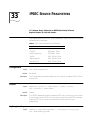
IPSEC SERVICE PARAMETERS
CONFiguration 61
CONTrol 61
KeyEncryptionKey 61
KeySet 62
ManualKeyInfo 63
manualPOLicy 63
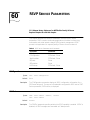
RSVP SERVICE PARAMETERS
CONFiguration 67
CONTrol 67
MaxFlowRate 68
REQuest 68
RESerVation 68
UDPEndcap 68
SR SERVICE PARAMETERS
AllRoutes 69
ROUte 70
SYS SERVICE PARAMETERS
CONFiguration
73
53
57
WEBLINK SERVICE PARAMETERS
StatPollInterval
75
NETBUILDER SOFTWARE VERSION
11.1 RELEASE NOTES
These release notes provide information on the following topics for NETBuilder®
software version 11.1:
■
■
■
■
■
■
■
■
■
■
■
■
Encryption Packages Notice
Supported platforms
New products
Supported PC flash memory cards
Approved DRAM SIMMs for the DPE Module
New Features and application notes
11.1 Software Packages
NETBuilder Upgrade Management Utilities
Notes and cautions
Known problems
Limitations
Changes and additions to the following guides:
Reference for NETBuilder Family Software
Using NETBuilder Family Software
If you have questions about the software, the guides, or these release notes,
contact 3Com or your network supplier.
For information on the command syntax used in these release notes, see “About
This Guide” in Using NETBuilder Family Software.
Encryption
Packages
Notice
The NETBuilder bridge/router software version 11.1 may contain strong
data encryption that cannot be exported outside the United States or
Canada. It is unlawful to export/re-export or transfer, either physically or
electronically, the encryption software or accompanying documentation
(or copies thereof) or any product(s) utilizing the encryption software or
such documentation without obtaining written authorization from the US
Department of Commerce.
Do not place NETBuilder software version 11.1 packages with encryption
on networks or servers that are accessible to users outside of the U.S. and
Canada.
Software packages with encryption include the following:
■
Part No. 86-0595-001
Published July 1998
NETBuilder II®
10
NETBUILDER SOFTWARE VERSION 11.1 RELEASE NOTES
■
■
Supported Platforms
NETBuilder software version 11.1 is available for the following platforms:
■
■
■
■
New Products
SuperStack II SI 5xx
(4-port)
Supported PC Flash
Memory Cards
Multi-protocol Router with 56-bit Encryption (DE)
Multi-protocol Router with 128-bit Encryption (DS)
SuperStack® II
IP/IPX/AT Router with 56-bit Encryption (NE) (SI model)
IP/IPX/AT Router with 128-bit Encryption (NS) (SI model)
Multi-protocol Router with 56-bit Encryption (CE) (SI model)
Multi-protocol Router with 128-bit Encryption (CS) (SI model)
Multi-protocol Router with 56-bit Encryption (TE) (Token Ring
models 327 and 527)
OfficeConnect®
IP/IPX/AT Router with 56-bit Encryption (NE)
IP/IPX/AT Router with 128-bit Encryption (NS)
Multi-protocol Router with Quick Step VPN and 56-bit Encryption (VE)
Multi-protocol Router with 56-bit Encryption (OE)
Multi-protocol Router with 128-bit Encryption (OS)
NETBuilder II
SuperStack II NETBuilder models 327 and 527
SuperStack II NETBuilder SI models 43x, 44x, 45x, 46x, 53x, 54x, 55x, and 56x
OfficeConnect NETBuilder models 11x, 12x (K and T variants),13x, and
14x (U and ST variants)
NETBuilder software version 11.1 supports the following new products:
This release integrates the 4-port WAN platform into the NETBuilder software
version 11.1 code base, which makes it possible to support all SuperStack II
NETBuilder SI, NETBuilder II, OfficeConnect NETBuilder, and SuperStack NETBuilder
327/527 bridge/routers on the same release of software.
Table 1 lists 3Com®_approved vendors of the PC flash memory card.
The 20 MB flash memory card has a formatted capacity of 19.86 MB. For dual
image and full dump capability, 3Com recommends using a 20 MB card.
You can also purchase the blank flash memory card from 3Com:
■
DPE 20 MB card is 3C6086
Table 1 Approved 20 MB Flash Memory Cards
Vendor and Description
Intel Series 2
Intel Series 2+
AMD Series D
Part Number
iMC020FLSA
iMC020FLSP
AmC020DFLKA
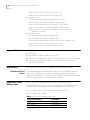
Approved DRAM SIMMs
Approved DRAM
SIMMs
Table 2 lists 3Com–approved vendors of the 32 MB DRAM SIMM for upgrading
the DPE 40 module.
Table 2
New Features
VPN Features
11
3Com–approved DRAM SIMMs
Size
Vendor and Description
Part Number
32 MB
NEC
MC428000A32B-60
72-pin 8Mx32 60 ns page mode
Toshiba
THM328020S-60
Toshiba
THM328020B5-60
This section describes new features in software version 11.1 for the
NETBuilder II, SuperStack II, and OfficeConnect NETBuilder bridge/routers.
Layer Two Tunneling Protocol
Layer Two Tunnelling Protocol (L2TP) is a standards-based protocol created from
combining two similar but incompatible proprietary tunneling protocols,
Point-to-Point Tunneling Protocol (PPTP) and L2F (Cisco’s tunneling protocol). L2TP
is primarily used in Virtual Private Networking (VPN) environments and allows the
creation of a tunnel between a remote site and a central site in order to transport
Layer 3 multiprotocol traffic (such as IP, IPX, and AppleTalk) over a public IP
network.
L2TP is a connection-oriented protocol that provides flow control, packet
sequencing, and retransmission capabilities. The transport network of L2TP can be
any packet-oriented network, but for this release, UDP/IP is the supported
transport network type. Similar to a PPTP connection, L2TP puts the data inside a
PPP frame and then encapsulates the frame with a UDP/IP header.
A notable difference between L2TP and PPTP is that PPTP precedes Layer 3 frames
with a GRE header and forwards them to IP via TCP, but L2TP precedes Layer 3
frames with its own protocol header (which looks similar to a GRE header) and
forwards them to IP via UDP.
From a security standpoint, L2TP by itself, like PPTP by itself, does not provide data
encryption, authentication, or integrity functions (other than those that exist with
IP and PPP) that are critical to maintaining VPN privacy. Also, L2TP does not provide
a mechanism for key management. These areas are for further development.
IPX RAS
With this release, the NETBuilder RAS service has been extended to include IPX
RAS support. The IPX RAS functionality implemented is Proxy routing (unlike IP
RAS which can be either LAN Extension or Proxy Routing). The NETBuilder
bridge/router routes IPX traffic between the external IPX network and the internal
“Proxy” IPX network. All the IPX clients share a single Proxy IPX network and sit
logically on the Proxy IPX network. Forwarding IPX traffic to clients is based on the
Node ID (MAC address) of each client.
12
NETBUILDER SOFTWARE VERSION 11.1 RELEASE NOTES
Additional RAS Enhancements
The RAS service has been enhanced in this release to add support for routers
acting as RAS clients. Support was added for the RADIUS attributes
“Framed_Route” and “Framed_Netmask.” Previous releases of software ignored
these attributes when/if the RADIUS server responded with them and provided a
"host" address and subnet mask to all RAS callers.
RAS services have been added to the SuperStack II NETBuilder SI (CF package) and
the NETBuilder II multiprotocol nonencrypted software (DW package).
Extensible Authentication Protocol
The PPP Extensible Authentication Protocol (EAP) is a general protocol for PPP
authentication that supports multiple authentication mechanisms. It is being
included in Windows NT 5.0 and simplifies support of token-based authentication.
This feature supports customers who use token card authentication systems with
NETBuilder bridge/routers as their network access servers. Specifically, only the
following authentication methods are supported:
■
MD5-Challenge
■
Generic Token Card
The Default Authentication Protocol parameter for the PPP Service does not
include a configuration option for EAP at the time of the 11.1 release. The
functionality will be available in a patch release for 11.1. Contact your 3Com
support representative for a patch version of the software that allows you to set
this parameter.
DHCP Proxy
During an IPCP negotiation, a remote client may ask for an IP address to be
assigned. The IP address can be obtained either through an internal IP address
pool or from an external DHCP server. To support dynamic IP address assignment
for RAS clients through an external DHCP server, the NETBuilder bridge/router
must act as a proxy agent on behalf of each remote client.
Encryption Strength
New levels of encryption strength and algorithms have been added to this release.
3Com has extended the encryption software to support up to 128 bits. RC5 and
3DES-2key have been added to the IPSEC feature set (MPPE will continue to use
RC4). For this release of 3DES, the key length is limited to up to 128 bits. In
3DES-2key (the implementation for 11.1) the first key is also used for the last key
(first key, second key, first key).
The “strong” encryption software upgrades and hardware ship kits are
recognizable via the 3CR number and the package identifiers.
< 128 bit support packages/kits contain:
■
A package identifier ending in ‘S’ (example, NS)
■
A 3CR number containing/ending in ‘92’ (examples, 3CR856792,
3CR6452P92FLASH)
New Features
13
< 56 bit support packages/kits contain:
■
A package identifier ending in ‘E’ (example, NE)
■
A 3CR number containing/ending in ‘91’ (examples, 3CR856791,
3CR6452P91FLASH)
Table 3 contains a summary of the encryption strengths and the associated
package ids.
Table 3 Summary of Encryption Strengths
Algorithm
Package ID
Encryption Key
Length
RC4
xE
40
xS
128
xE
56
xS
128
xE
56
xS
56
xS
112
RC5
DES
3DES (2 key)
RSVP
RSVP is a dynamic quality of service (QoS) setup protocol that enables IPv4-based
real time applications to reserve resources at network nodes along the
sender-to-receiver data path to meet its quality of service requirements. RSVP
monitors and enforces bandwidth reservations for outbound QoS traffic on PPP
and Frame Relay virtual ports. The Phase 1 RSVP message processing engine
conforms to RFC 2205 and its application to Integrated Services as defined in RFC
2210. NETBuilder bridge/router-specific flow admission control, packet
classification, and packet scheduling mechanisms are implemented to provide the
controlled-load QoS control services as specified in RFC 2211. Both IPv4 unicast
and multicast (over DVMRP/MOSPF domains) flows are supported.
New and Enhanced
Protocol Features
This section describes new and enhanced protocol features.
Virtual Router Redundancy Protocol (VRRP) Phase 2
The Virtual Router Redundancy Protocol (VRRP) is designed to eliminate the single
point of failure inherent in the static default routed environment. VRRP specifies
an election protocol that dynamically assigns responsibility for a virtual router to
one of the VRRP routers on a LAN. This is the second phase of VRRP. This phase
adds FDDI to the currently supported media (Ethernet and Fast Ethernet). Phase II
(similar to the initial implementation) will not support source route for VRRP
advertisements (that is, the VRRP routers that belong to the same VRID cannot be
separated by source route bridges.)
Virtual Circuit Prioritization
Frame Relay Virtual Circuit Prioritization extends the current queue handling
capabilities of PPP ports to Frame Relay virtual circuits. The FR virtual circuit can be
either a FR virtual port or a virtual circuit associated only with the parent port. All
14
NETBUILDER SOFTWARE VERSION 11.1 RELEASE NOTES
of the queue policies, Priority Queuing, and Protocol Reservation are supported. In
addition to the currently supported policies, a metering algorithm has been added.
If the queue handler detects that the underlying bandwidth exceeds a certain
threshold specified, then the queueing and metering functions are effectively
bypassed and packets are transmitted directly without queuing. This optimizes
high-speed interfaces in which the customer assumes that everything presented to
the interface can be transmitted without going through the prioritization or
metering processing and without much fear of packet loss.
Firewall Enhancements
The recent enormous growth in the Internet has increased the security risks to
corporate and government networks. The existing Firewall Service has been
enhanced to support more predefined filters for popular applications, to allow you
to create your own filter definitions, and to combine noncontiguous IP addresses
into named groups to which firewall policies may be applied.
Firewall enhancements include:
■
Predefined service filters for multimedia applications such as Real Networks’
RealPlayer.
■
The ability to define a service and group of IP addresses.
■
Support for traceroute.
■
Additional predefined service filters.
■
Secure HTTP
■
BGP-4
■
Finger
■
Whois
■
SOCKS
■
DNS client-to-server.
■
IPSEC support for Encapsulated Security Payload (ESP) headers and
Authentication Headers (AH).
IP Version 6 (Phase II)
IPv6 Phase II features include the BGP-4 multiprotocol extensions for IPv6
inter-domain routing plus native IPv6 routing over PPP and point-to-point ATM
PVCs.
BGP-4 Enhancements
Enhancements have been incorporated that address the scaling issues with the
current BGP implementation. The new implementation also includes BGP-4+
features. BGP-4+ is an extension to the existing BGP protocol for handling
multiprotocol routing. For example, it enables interdomain routing of IPv4
multicast, IPv6 unicast, and IPv6 multicast network layers. The following network
layer reachability information attributes are implemented:
■
Multiprotocol Reachable NLRI
■
Multiprotocol Unreachable NLRI
New Features
15
OSPF Not-So-Stubby-Area (NSSA)
For inter-area routing, the Area Border Router (the only attachment to the
backbone for leaf sites) advertised a default route. However, when fairly complex
leaf sites are connected to the backbone via a Stub Area, inter-area routing into
and out of the leaf site is not optimal with only a default route. RFC 1587
proposes a new kind of area known as NSSA (Not-So-Stubby-Area) to address this
problem. NETBuilder software version 11.1 implements this new functionality.
Frame Relay PVC Q.933 Support
ITU Q.933 Annex A Frame Relay PVC signaling is the latest defined by ITU that
supports asynchronous bidirectional PVC control procedure. With the
implementation of this new signaling standard, you can signal the network for the
activation or deactivation of individual PVCs. Additionally, you can query the
network regarding the operational status of the PVC. Q.933 Annex A is a super set
of the existing LMI supported in the NETBuilder bridge/router platforms.
Data Over Voice (B-Channel ISDN Specification)
This feature enables the bridge/router to initiate an ISDN 56 Kbps data call over
the ISDN voice bearer channel. Connection at the remote end must be able to
accept the incoming call and supply the proper signal to disable echo suppressors.
This feature is sometimes referred to as Switched 56 Permissive mode or TollSaver.
See “Placing a Data Over Voice Call” on page 17 for brief description of how to
use this feature.
System Features
This release implements the following general system features.
Boundary Router Remote LAN Detection
Central site support of Boundary Routing Architecture has been enhanced to
detect the LAN media type of the connected remote boundary routers.
MBRI Digi64S2 Support
This release implements the German dual point-to-point leased line switch
specification Digi64S2, on the NETBuilder II bridge/router 8-port BRI Module.
Digi64S2 was implemented in prior releases of the OfficeConnect NETBuilder
bridge/router and SuperStack II NETBuilder SI bridge/router product lines
containing ISDN interfaces. This feature allows each ISDN port on the NETBuilder
to be connected to either the same or different remote node locations as a leased
line. See “Digi64S2” on page 18 for a brief description of how to use this feature.
Legacy/ATM Features
This software release implements the following legacy and ATM features.
Multiprotocol over ATM (MPOA)
An ATM network can be divided into multiple logical internet subnets (LISs) or
emulated LANs (ELANs), which requires that all ELAN traffic go through routers
that are connected to the ELANs. The NETBuilder II bridge/router in a LAN
emulation topology is used to perform the routing between the ELANs in which
the NETBuilder II bridge/router has joined. On a large site, it is quite likely that
there would be two or more routers on the data path between the edge devices. If
16
NETBUILDER SOFTWARE VERSION 11.1 RELEASE NOTES
the two edge devices are both physically attached to the same ATM network
fabric, then the edge devices should be able to communicate directly with each
other, bypassing one or more intermediate routers in the data path.
Multiprotocol Over ATM (MPOA) is used to bypass the intermediate routers. It
allows the edge devices to resolve their ATM address and setup the short-cut
connections between each other. MPOA consists of the MPOA server (co-located
with routers) and the MPOA client (co-located with edge devices). The NETBuilder
II bridge/router serves as an MPOA server, which provides the information required
by MPOA clients (edge devices) to setup the short-cut connections.
Token Ring in Fast Ethernet (TIFE)
Token Ring in Fast Ethernet (TIFE) is a method for tunneling token ring frames,
including source route information, through a Fast Ethernet network. For
customers with an existing token ring infrastructure, TIFE provides a gradual
migration path to an Ethernet LAN, preserving the investment in capital
equipment and source route sensitive applications. For the NETBuilder
bridge/router, TIFE provides a means to support token ring media without
requiring a token ring interface. In addition, the 802.1Q VLAN support required
for TIFE allows the routing protocols to access Ethernet and Fast Ethernet VLANs.
(VLAN over FDDI or token ring is not supported with this release.)
Network Management
Features
This release adds the following new network management features.
ASCII Boot
The ASCII LoadConfigs feature on the NETBuilder bridge/router has been
expanded to provide a way for an ASCII text file to be executed automatically
when the router is booted. Along with this new functionality, a new Transcend®
Network Application Tool (available Fall 1998) called NETBuilder Configurator, will
provide an easy mechanism for setting up multiple routers to use the ASCII boot
feature. NETBuilder Configurator will provide a straightforward spreadsheet GUI
interface for you to build and deploy ASCII text files based on custom made
templates.
The ASCII boot feature simplifies the management of a network allowing you to
mange the configuration of your own router with a single ASCII text configuration
file.
56/64K CSU/DSU External Loopback
OfficeConnect NETBuilder and SuperStack II SI NETBuilder bridge/router platforms
with a CSU/DSU option installed have a new remote loopback capability. The
remote loopback functions include Remote CSU Loopback and Remote DSU
Loopback. The Remote Loopback can be started/terminated via SNMP. The
Remote initiated Local V54 loopback has the same functionality as the existing
V54 Loopback from the console.
NETBuilder Web Link Improvements
The NETBuilder Web Link application has been improved to include the following
enhancements:
New Features Application Notes
■
Improved error handling
■
Help frame resizing now persists across page changes
■
A logout icon for improved security
■
Port list support
■
Support for user-level password changing
17
Upgrade Management Utilities and NETBuilder Upgrade Link
The remote upgrade process consists of providing customers with a reliable, easy,
and clearly defined way of upgrading their NETBuilder bridge/routers to a newer
version of software and/or firmware. The following changes have been
implemented in this release:
■
Default support for upgrades from 8.x, 9.x, 10.x, or 11.0 to version 11.1
■
Support for FTP file transfers
■
Named backup and restores
■
Improved Upgrade Link user interface with the following:
■
FTP file transfers
■
Stage control
■
Ability to delete old packages
■
Ability to run in client/server mode
See “NETBuilder Upgrade Management Utilities” on page 30 for more
information and Upgrading NETBuilder Family Software for Upgrade Link
operating instructions.
Flash Load
The prior (software versions 11.0 and earlier) flash load process was limited to
formatting the on-board Flash PROM file storage and copying the bundle image to
the firmware and the NETBuilder core boot file onto the file system. With the
introduction of Web, this process needed to be modified to include flash copying
all the appropriate Web Link files as well. This feature allows for multiple file
loading support with the flash load command. This functionality is limited to the
OfficeConnect NETBuilder and SuperStack II SI NETBuilder bridge/router platforms.
New Features
Application Notes
Placing a Data Over
Voice Call
This section provides application notes for the following features:
■
Data over Voice (B-Channel ISDN Specification)
■
Digi64S2
■
ASCII Boot
In many areas, voice calls over ISDN are charged at a lower rate than data calls.
This release of software allows you to specify that calls to a given number be
established as voice calls. This feature is sometimes referred to as a TollSaver
capability. Telephone companies often refer to this type of call as Switched 56
Permissive. The answering device must be capable of generating the 2.1KHz tone
18
NETBUILDER SOFTWARE VERSION 11.1 RELEASE NOTES
needed to disable any echo cancellers on the line. Consult with the owner of the
destination equipment to see whether it has this capability.
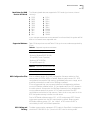
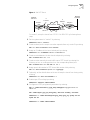
In order to configure this feature, you must define the DialNoList entry with a type
of BriV, by entering:
ADD !<port> -POrt DialNoList "<phone number>" Type=BriV
The Baud specifier in the ADD command, although not disallowed, is ignored if
present. Data sent over the B channel will only be sent at 56 Kbps.
Example
To place a data over voice call on port 2 to an ISP with the phone number
453-4444, enter:
ADD !2 -POrt DialNoList “4534444” Type=BriV
DIal !2
Digi64S2
There are two ISDN leased line linetypes for ISDN lease lines in Germany: Digi64S
and Digi64S2. Digi64S can run only on the B1 channel, but Digi64S2 can run on
both the B1 and the B2 channels.
1 To enable the Digi64S2 feature, first set the linetype parameter to Digi64S2. Type:
SETDefault !2.1 -PAth LineType = Digi64S2 ( abbreviated d64s2 )
SETDefault !2.2 -PAth LineType = Digi64S2
2 Toggle the respective paths. Type:
SETDefault !2.1 -PAth cont=e
SETDefault !2.2 -PAth cont=e
Path 2.1 is mapped to the B1 channel and path 2.2 is mapped to the B2 channel.
This mapping is not interchangeable.
If one of the paths is set to Digi64S2, the path in the same connector line is also
set to Digi64S2. Mixtures of line types within a single connector are not
supported.
3 On systems using the HSS 8 port BRI module, make the paths static before you
change the line type.
SETDefault !2e.1 -PAth DialCONTrol=STAtic
SETDefault !2e.2 -PAth DialCONTrol=STAtic
ADD !2e.1 -POrt PAth 2e.1
ADD !2e.2 -POrt PAth 2e.2
SETDefault !2e.1 -PAth LineType=Digi64s2 CONTrol=e
SETDefault !2e.2 -PAth LineType=Digi64s2 CONTrol=e
ASCII Boot
The LoadConfigs function has been enhanced to provide a way to maintain the
configuration of the router in a single ASCII text file. During router initialization,
the old configuration is deleted, and the router is reconfigured from scratch by
executing an ASCII text file. This feature is invoked by setting up the ASCII text file
in the configuration directory with the name BOOT.CFG.
New Features Application Notes
19
WARNING: For network security, do not include security sensitive information
such as passwords. The ASCII text file is not encyrpted, which means the
passwords are readable by anyone who has access to the file.
When the router is booted and the BOOT.CFG file is detected in the configuration
directory, all existing configuration files (except CCSMACRO and IOXM) in the
configuration directory are deleted. The configuration commands in the
BOOT.CFG file are then executed. If a configuration command fails to execute
successfully, it does not stop, but continues with the next configuration command.
Just as when you enter a configuration command on the command line, new
encoded configuration files are created. As long as the file BOOT.CFG is detected
in the configuration directory, this operation is repeated every time the router is
rebooted.
To suspend this operation and use the encoded configuration files when the router
is rebooted, the BOOT.CFG file can be renamed (ReName command is now
supported by LoadConfigs) as the last command in the BOOT.CFG file.
To minimize the impact of executing configuration commands at boot time, the
configuration commands are not displayed. However, as with normal LoadConfigs
operations, a log file is created, which contains the configuration commands that
were executed along with any comments from the BOOT.CFG file and system
messages that may have been generated.
If the router has intelligent I/O modules (6 port Ethernet, ATM module, Multiport
BRI modules), they are loaded before any of the commands are executed. The
"System Initialized and Running" message is not displayed (that is, no user
interaction is possible) until after all of the commands in the BOOT.CFG file have
executed. If the ASCII boot feature has been invoked, a message appears as part
of the SysconF command Boot Statistics information to indicate this.
Configuration changes executed after the router is booted are not automatically
captured in the BOOT.CFG file and would be lost if the router was rebooted. Also,
the execution of the ASCII boot feature does not affect any macros that have been
defined or the SysconF configuration.
After booting with the boot.cfg file, any changes made to the device via telnet,
console, SNMP, or web interface are not saved to the boot.cfg file. It is
recommended that you make all changes in the boot.cfg file directly.
20
NETBUILDER SOFTWARE VERSION 11.1 RELEASE NOTES
11.1 Software
Packages
NETBuilder II
The tables in this section list the features in the packages available in software
version 11.1 for the NETBuilder bridge/router platforms.
Table 4 lists the software features of each package for NETBuilder II bridge/routers.
Table 4 NETBuilder II Software Features
Feature
Bridging
Boundary Routing® central node
Routing Protocols
IPv4
IPv6
IP services:
Multicast IP
OSPF
Network Address
Translation (NAT)
BGP
VRRP
DHCP
DHCP Proxy
RIP/RIP v2/NTP
IP connection services
RSVP
IP security:
IPsec
DES
3DES
RC5
MPPE/RC4
MS-CHAP
Firewall
RAS
IPX RAS
RAS Traps
IPX
XNS
OSI
OSI connection services
VINES
DECnet
AppleTalk
WAN Protocols
PPP/Multilink PPP
PPTP
L2TP
EAP
Software Package
APPN/Connection
Services (AC)
Multiprotocol Router (DW)
X
X
X
X
Multiprotocol
Router with 56-bit
Encryption (DE)
X
X
Multiprotocol Router
with 128-bit
Encryption (DS)
X
X
X
X
X
X
X
X
X
X
X
X
X
X
X
X
X
X
X
X
X
X
X
X
X
X
X
X
X
X
X
X
X
X
X
X
X
X
X
X
X
X
X
X
X
X
X
X
X
X
X
X
X
X
X
X
X
X
X
X
X
X
X
X
X
X
X
X
X
X
X
X
X
X
X
X
X
X
X
X
X
X
X
X
X
X
X
X
X
X
X
X
X
X
X
X
X
X
X
X
X
X
X
X
X
X
X
X
11.1 Software Packages
21
Table 4 NETBuilder II Software Features (continued)
Feature
Frame Relay
SMDS
X.25
X.25 switching/tunneling
IBM Protocols
APPN
DLSw
BRITSS
LAA
LNM
Polled ASYNC/
BISYNC Passthrough
NetView Service Point
SDLC
SHDLC
BSC conversion
QLLC/LLC2 conversion
Other Features
FTP
Data over Voice
MPOA
ASCII Boot
Zmodem
Dial-on-demand
Web Link
Virtual Ports (512 max.)
ISDN
TIFE
Software Package
APPN/Connection
Services (AC)
Multiprotocol Router (DW)
X
X
X
X
X
X
X
X
X
X
X
X
X
X
Multiprotocol
Router with 56-bit
Encryption (DE)
X
X
X
X
Multiprotocol Router
with 128-bit
Encryption (DS)
X
X
X
X
X
X
X
X
X
X
X
X
X
X
X
X
X
X
X
X
X
X
X
X
X
X
X
X
X
X
X
X
X
X
X
X
X
X
X
X
X
X
X
X
X
X
X
X
X
X
X
X
X
X
X
X
X
X
X
X
X
X
X
X
X
X
X
X
X
X
X
X
NETBuilder II Firmware Requirements
The NETBuilder II I/O modules require firmware upgrades to support the
NETBuilder software version 11.1 (see Table 5 for firmware requirements).
You can determine your I/O module firmware version through the software by
entering:
SHow -SYS IOI
Table 5 NETBuilder II Firmware Requirements
Module
11.1 Firmware Version Strings
DPE
FW/DPE-BOOT1,1.4
FW/DPE-BOOT2,1.4
MP 6-port Ethernet
FW/6ETH-FW,1.4.0.70
Fast Ethernet 100Base
FW/ETH100-FW,1.9
BRI 8-port
FW/8BRI-FW,1.2
MP ATMLink
FW/ATM-FW,1.1.0.70
22
NETBUILDER SOFTWARE VERSION 11.1 RELEASE NOTES
Table 5 NETBuilder II Firmware Requirements
SuperStack II SI
Module
11.1 Firmware Version Strings
HSS 3-port (V.35)
FW/HSS3-V35,1.1.9
HSS 3-port (RS449)
FW/HSS3-449,1.1.9
HSS 3-port (RS232)
FW/HSS3-232,1.1.9
HSS 4-port
FW/4PORTWAN-FW,1.2
Table 6 lists the software features of each package for SuperStack II SI
bridge/routers.
Table 6 SuperStack II NETBuilder SI Software Features
Model and Software Package
432, 442,
452, 462,
532, 542,
552, 562
Feature
Bridging
Boundary Routing® central
node
Boundary Routing leaf node
Routing Protocols
IPv4
IP services:
Multicast IP
OSPF
Network Address
Translation (NAT)
BGP
VRRP
DHCP
DHCP Proxy
RIP/RIP v2/NTP
IPCP
IP connection services
IP security:
IPsec
DES
3DES
RC5
MPPE/RC4
MS-CHAP
Firewall
RAS
IPX RAS
IP/IPX/AT
Router
(NW)
X
432, 442,
452, 462,
532, 542,
552, 562
432, 442,
452, 462,
532, 542,
552, 562
IP/IPX/AT
Router
IP/IPX/AT
with
Router
with 56-bit 128-bit
Encryption Encryption
(NS)
(NE)
X
X
437, 447,
457, 467,
437, 447, 537, 547,
457, 467, 557, 567
537, 547,
Multi431, 441, 557, 567
protocol
451, 461
Router with
MultiBoundary protocol 56-bit
Encryption
Router
Router
(CE)
(CF)
(BF)
X
X
X
X
X
437, 447,
457, 467,
537, 547,
557, 567
Multiprotocol
Router with
128-bit
Encryption
(CS)
X
X
438, 448,
458, 468
APPN/
Connection
Services
(AX)
X
X
X
X
X
X
X
X
X
X
X
X
X
X
X
X
X
X
X
X
X
X
X
X
X
X
X
X
X
X
X
X
X
X
X
X
X
X
X
X
X
X
X
X
X
X
X
X
X
X
X
X
X
X
X
X
X
X
X
X
X
X
X
X
X
X
X
X
X
X
X
X
X
X
X
X
X
X
X
X
X
X
X
X
X
X
X
X
X
X
X
X
X
X
X
X
X
X
X
X
X
X
X
X
X
X
X
X
11.1 Software Packages
23
Table 6 SuperStack II NETBuilder SI Software Features (continued)
Model and Software Package
432, 442,
452, 462,
532, 542,
552, 562
Feature
RAS Traps
IPX
XNS
OSI
OSI connection
services
VINES
DECnet
AppleTalk
BR Remote LAN Detection
WAN Protocols
PPP/Multilink PPP
PPTP
L2TP
EAP
Frame Relay
SMDS
X.25
X.25 switching/tunneling
IBM Protocols
APPN
DLSw
BRITSS
LAA
NetView Service Point
Polled ASYNC/
BISYNC Passthrough
SDLC
SHDLC
BSC conversion
QLLC/LLC2 conversion
Other Features
Data over Voice
CSU/DSU Loopback
FTP
Zmodem
Dial-on-demand
Web Link
ASCII BOOT
TIFE
IP/IPX/AT
Router
(NW)
X
X
432, 442,
452, 462,
532, 542,
552, 562
IP/IPX/AT
Router
with 56-bit
Encryption
(NE)
X
X
X
432, 442,
452, 462,
532, 542,
552, 562
IP/IPX/AT
Router
with
128-bit
Encryption
(NS)
X
X
437, 447,
457, 467,
437, 447, 537, 547,
457, 467, 557, 567
537, 547,
Multi431, 441, 557, 567
protocol
451, 461
Router with
MultiBoundary protocol 56-bit
Encryption
Router
Router
(CE)
(CF)
(BF)
X
X
X
X
X
X
X
X
X
437, 447,
457, 467,
537, 547,
557, 567
Multiprotocol
Router with
128-bit
Encryption
(CS)
X
X
X
X
438, 448,
458, 468
APPN/
Connection
Services
(AX)
X
X
X
X
X
X
X
X
X
X
X
X
X
X
X
X
X
X
X
X
X
X
X
X
X
X
X
X
X
X
X
X
X
X
X
X
X
X
X
X
X
X
X
X
X
X
X
X
X
X
X
X
X
X
X
X
X
X
X
X
X
X
X
X
X
X
X
X
X
X
X
X
X
X
X
X
X
X
X
X
X
X
X
X
X
X
X
X
X
X
X
X
X
X
X
X
X
X
X
X
X
X
X
X
X
X
X
X
X
X
X
X
X
X
X
X
X
X
X
X
X
X
X
X
X
X
X
X
X
X
X
X
X
X
X
X
X
X
X
X
X
X
X
X
X
X
X
X
X
X
X
X
X
X
X
X
X
X
X
X
X
X
X
X
X
X
X
X
X
X
X
X
X
X
X
X
X
X
X
24
NETBUILDER SOFTWARE VERSION 11.1 RELEASE NOTES
Table 6 SuperStack II NETBuilder SI Software Features (continued)
Model and Software Package
432, 442,
452, 462,
532, 542,
552, 562
Feature
Flash Load
Virtual Ports (48 max.)
Memory Requirements
DRAM:
Flash memory:
SuperStack II Token Ring
IP/IPX/AT
Router
(NW)
X
X
432, 442,
452, 462,
532, 542,
552, 562
432, 442,
452, 462,
532, 542,
552, 562
IP/IPX/AT
Router
with 56-bit
Encryption
(NE)
X
X
IP/IPX/AT
Router
with
128-bit
Encryption
(NS)
X
X
16 MB
8 MB
16 MB
8 MB
16 MB
8 MB
437, 447,
457, 467,
437, 447, 537, 547,
457, 467, 557, 567
537, 547,
Multi431, 441, 557, 567
protocol
451, 461
Router with
MultiBoundary protocol 56-bit
Encryption
Router
Router
(CE)
(CF)
(BF)
X
X
X
X
X
X
16 MB
8 MB
16 MB
8 MB
16 MB
8 MB
437, 447,
457, 467,
537, 547,
557, 567
Multiprotocol
Router with
128-bit
Encryption
(CS)
X
X
438, 448,
458, 468
APPN/
Connection
Services
(AX)
X
X
16 MB
8 MB
16 MB
8 MB
Table 7 lists software features for each package for the SuperStack II
bridge/routers.
Table 7 SuperStack II NETBuilder Ethernet and Token Ring Features
Models 327
(Token Ring)
Models 527
(Token Ring)
Multiprotocol
Router with
56-bit Encryption
(TE)
Multiprotocol
Router with 56-bit
Encryption
(TE)
X
X
X
X
X
X
Multicast IP
X
X
OSPF
X
X
Network Address Translation (NAT)
X
X
DHCP
X
X
DHCP Proxy
X
X
RIP/RIP v2/NTP
X
X
IPsec
X
X
Firewall
X
X
IPX
X
X
XNS
X
X
OSI
X
X
VINES
X
X
DECnet
X
X
AppleTalk
X
X
Features
Bridging
Boundary
Routing®
central node
Routing Protocols
IPv4
IP services:
VRRP
IP security:
11.1 Software Packages
Table 7 SuperStack II NETBuilder Ethernet and Token Ring Features (continued)
Models 327
(Token Ring)
Models 527
(Token Ring)
PPP/Multilink PPP
X
X
PPTP
X
X
L2TP
X
X
Frame Relay
X
X
SMDS
X
X
X.25
X
X
X.25 switching/tunneling
X
X
DLSw
X
X
BRITSS
X
X
LAA
X
X
Polled ASYNC/BISYNC Passthrough
X
X
SDLC
X
X
SHDLC
X
X
QLLC/LLC2 conversion
X
X
FTP
X
X
Dial-on-demand
X
X
Features
WAN Protocols
IBM Protocols
Other Features
Data over voice
X
Web Link
X
X
Virtual Ports (28 max.)
X
X
DRAM:
16 MB
16 MB
Flash memory for automatic recovery when
upgrading:
4 MB
8 MB
Flash memory for manual recovery when
upgrading:
4 MB
4 MB
Memory Requirements
OfficeConnect
Table 8 and Table 9 list software features for each package for OfficeConnect
bridge/routers.
Table 8 OfficeConnect NETBuilder Software Features
Model and Software Package
120
Feature
Bridging
Boundary Routing® central node
Boundary Routing leaf node
112, 122,
132, 142
FRAD IP/IPX/AT
(FD) Router (NW)
X
X
112, 122,
132, 142
112, 122,
132, 142
IP/IPX/AT
Router with
56-bit
Encryption
(NE)
X
IP/IPX/AT
Router with
128-bit
Encryption
(NS)
X
145
111, 121,
Quick Step
131, 141
VPN Router
Boundary with 56-bit
Encryption
Router
(VE)
(BF)
X
X
X
25
26
NETBUILDER SOFTWARE VERSION 11.1 RELEASE NOTES
Table 8 OfficeConnect NETBuilder Software Features (continued)
Model and Software Package
112, 122,
132, 142
112, 122,
132, 142
FRAD IP/IPX/AT
(FD) Router (NW)
IP/IPX/AT
Router with
56-bit
Encryption
(NE)
IP/IPX/AT
Router with
128-bit
Encryption
(NS)
X
X
X
X
X
X
X
X
X
X
X
X
X
X
X
X
X
X
X
X
X
X
X
X
X
X
X
X
X
X
X
X
X
X
X
X
X
X
X
X
X
X
X
X
X
X
X
X
X
X
X
X
X
X
X
X
X
120
Feature
Routing Protocols
IPv4
IP services:
Multicast IP
OSPF
Network Address
Translation (NAT)
VRRP
DHCP
RIP/RIP v2/NTP
DHCP Proxy
IPCP
IP security:
IPsec
DES
3DES
RC5
Firewall
IPX
XNS
OSI
VINES
DECnet
AppleTalk
BR Remote LAN Detection
WAN Protocols
PPP/Multilink PPP
PPTP
L2TP
Frame Relay
SMDS
X.25
X.25 switching/tunneling
IBM Protocols
APPN
DLSw
BRITSS
LAA
NetView Service Point
Polled ASYNC/
BISYNC Passthrough
SDLC
X
112, 122,
132, 142
145
111, 121,
Quick Step
131, 141
VPN Router
Boundary with 56-bit
Encryption
Router
(VE)
(BF)
X
X
X
X
X
X
X
X
X
X
X
X
X
X
X
X
X
X
X
X
X
X
X
X
X
X
X
X
X
X
X
X
X
X
X
X
X
X
X
X
X
X
X
X
X
X
X
X
X
X
X
X
X
X
X
X
X
X
11.1 Software Packages
27
Table 8 OfficeConnect NETBuilder Software Features (continued)
Model and Software Package
120
Feature
SHDLC
BSC conversion
QLLC/LLC2 conversion
Other Features
FTP
Data over Voice
CSU/DSU Loopback
Zmodem
Dial-on-demand
Quick Step VPN application
ASCII Boot
Flash Load
Web Link
Virtual Ports (28 max.)
Memory Requirements
DRAM:
Flash memory for automatic
recovery when upgrading:
Flash memory for manual
recovery when upgrading:
112, 122,
132, 142
FRAD IP/IPX/AT
(FD) Router (NW)
X
X
X
X
X
112, 122,
132, 142
112, 122,
132, 142
IP/IPX/AT
Router with
56-bit
Encryption
(NE)
IP/IPX/AT
Router with
128-bit
Encryption
(NS)
145
111, 121,
Quick Step
131, 141
VPN Router
Boundary with 56-bit
Encryption
Router
(VE)
(BF)
X
X
X
X
X
X
X
X
X
X
X
X
X
X
X
X
X
X
X
X
X
X
X
X
X
X
X
X
X
X
X
X
X
X
X
X
X
X
X
X
X
X
X
X
X
X
X
X
X
X
X
8 MB 8 MB
8 MB 8 MB
8 MB
8 MB
8 MB
8 MB
8 MB
8 MB
8 MB
8 MB
4 MB 4 MB
4 MB
4 MB
4 MB
4 MB
X
X
Table 9 Additional OfficeConnect NETBuilder Models Software Features
Feature
Bridging
Boundary Routing® central node
Boundary Routing leaf node
Routing Protocols
IPv4
IP services:
117, 127,
117, 127, 137, 147
137, 147
Multiprotocol
Multipro- Router with
116, 126,
56-bit
tocol
136, 146
Encryption
Router
(OE)
APPN (AF) (OF)
X
X
X
X
X
117, 127,
137, 147
X
X
X
X
Multiprotocol
Router with
128-bit
Encryption
(OS)
X
X
28
NETBUILDER SOFTWARE VERSION 11.1 RELEASE NOTES
Feature
Multicast IP
OSPF
Network Address
Translation (NAT)
VRRP
DHCP
DHCP Proxy
RIP/RIP v2/NTP
IPCP
IP security:
IPsec
DES
3DES
RC5
Firewall
IPX
XNS
OSI
VINES
DECnet
AppleTalk
WAN Protocols
PPP/Multilink PPP
PPTP
L2TP
Frame Relay
SMDS
X.25
X.25 switching/tunneling
IBM Protocols
APPN
DLSw
BRITSS
LAA
NetView Service Point
Polled ASYNC/
BISYNC Passthrough
SDLC
SHDLC
BSC conversion
QLLC/LLC2 conversion
Other Features
Data over Voice
CSU/DSU Loopback
FTP
117, 127,
117, 127, 137, 147
137, 147
Multiprotocol
Multipro- Router with
116, 126,
56-bit
tocol
136, 146
Encryption
Router
(OE)
APPN (AF) (OF)
X
X
X
X
X
X
X
X
X
117, 127,
137, 147
X
X
X
X
X
X
X
X
X
X
X
X
X
X
X
X
X
X
X
X
X
X
X
X
X
X
X
X
X
X
X
X
X
X
X
X
X
X
X
X
X
X
X
X
X
X
X
X
X
X
X
X
X
X
X
X
X
X
X
X
X
X
X
X
X
X
X
X
X
X
X
X
X
X
X
X
X
X
X
X
X
X
X
X
X
X
X
X
X
X
X
X
X
X
X
X
X
X
X
X
X
X
X
X
X
X
X
X
X
X
X
X
X
X
X
X
X
X
X
X
X
X
X
X
Multiprotocol
Router with
128-bit
Encryption
(OS)
X
X
X
11.1 Software Packages
Feature
Zmodem
Dial-on-demand
Quick Step VPN application
ASCII Boot
Flash Load
Web Link
Virtual Ports (28 max.)
Memory Requirements
DRAM:
Flash memory for automatic
recovery when upgrading:
Flash memory for manual
recovery when upgrading:
117, 127,
117, 127, 137, 147
137, 147
Multiprotocol
Multipro- Router with
116, 126,
56-bit
tocol
136, 146
Encryption
Router
(OE)
APPN (AF) (OF)
X
X
X
X
X
X
117, 127,
137, 147
X
X
X
X
X
X
X
X
X
X
X
X
X
X
X
X
16 MB
8 MB
16 MB
8 MB
16 MB
8 MB
16 MB
8 MB
4 MB
4 MB
4 MB
4 MB
29
Multiprotocol
Router with
128-bit
Encryption
(OS)
X
X
30
NETBUILDER SOFTWARE VERSION 11.1 RELEASE NOTES
Item Not Supported
NETBuilder Upgrade
Management Utilities
The NETBuilder software version 11.1 does not support the following
bridge/routers:
■
SuperStack II NETBuilder 227 Full Router (Ethernet)
■
SuperStack II NETBuilder 427 Router (Ethernet, ISDN)
This section includes information about NETBuilder software version 11.1
NETBuilder Upgrade Management Utilities. Upgrade Link is a graphical
interface-based application designed to simplify upgrading the NETBuilder
bridge/router operating software.
The NETBuilder software version 11.1 NETBuilder Upgrade Management Utilities
support upgrades from NETBuilder bridge/routers running version 8.x through
11.0.1. If you need to upgrade from version 7.x to 11.1, you need to perform the
upgrade in two steps. The first step requires upgrading from 7.x to 9.3.1. After the
NETBuilder bridge/router configuration files have been converted to 9.3.1, they
can then be further upgraded to support the 11.1 release. The 9.3.1 Remote
Upgrade Utilities and manual are available on the 3Com InfoDeli website.
Downloading
NETBuilder Upgrade
Management Utilities
The NETBuilder Upgrade Management Utilities is shipped on the CD-ROM with
every NETBuilder software release. In addition, the NETBuilder Upgrade
Management Utilities can be downloaded from the FTP site (ftp.3com.com), from
the World Wide Web access through http://infodeli.3com.com/, or from the 3Com
bulletin board service (BBS) under Software Downloads, System Software. The files
range in size from 1 MB to 4 MB per file and are usually easier and faster to
retrieve using the FTP site.
UNIX Files
The NETBuilder Upgrade Management Utilities are UNIX files compressed with
the UNIX compress utility. To use the downloaded files, you must first expand
the files using the UNIX decompress utility. For instructions on how to download
and decompress the utilities, see the ruu111.txt file.
The UNIX files are as follows:
ruusol111.1
ruuhp111.1
ruuaix111.1
ruu111.txt
Windows Files
Contains the UNIX-compressed NETBuilder Upgrade Management
Utilities for the Solaris 2.5 platforms.
Contains the UNIX-compressed NETBuilder Upgrade Management
Utilities for the HP-UX 10.x platforms.
Contains the UNIX-compressed NETBuilder Upgrade Management
Utilities for the IBM AIX 4.1.1 through 4.2.X platforms.
Contains the instructions for downloading and decompressing
the NETBuilder Upgrade Management Utilities. This file also
contains instructions on how to integrate the utilities into the
Transcend Enterprise Manger application.
The NETBuilder Upgrade Management Utilities are Windows files compressed
with a compression utility. To use the downloaded files, you must first expand
them using the decompress utility PKUNZip. PKUNZip can be downloaded from
the following URLs:
http://www.pkware.com
NETBuilder Upgrade Management Utilities
31
or
http://infodeli.3com.com/infodeli/swlib
For instructions on how to decompress and install the utilities, see the
ruu111.txt file.
The Windows files are as follows:
ruu111.zip Contains the compressed NETBuilder Upgrade Management
Utilities for Windows95 and Windows NT version 4.0 platforms.
ruu111.txt Contains the instructions for downloading and decompressing
the NETBuilder Upgrade Management Utilities. This file also
contains instructions on how to integrate the utilities into the
Transcend Enterprise Manger application.
Executing
profile.bat
When using the 11.1 NETBuilder Upgrade Management Utilities from a Windows
command line, you must execute the profile.bat
(/user/3com/common/data/profile.bat) file. This file sets up the path to
\usr\3com\common\bin where the utilities reside. Alternatively you can reboot
your system so that the changed in the a autoexec.bat file can take effect.
Version 11.1 NETBuilder
Upgrade Management
Utilities
The upgrade utilities, Transcend Enterprise Manager for Windows 95 v 6.1, and
Transcend Enterprise Manager for Windows 97 NT are available for use on
Windows 95 and Windows NT platforms. These utilities also support Transcend
Enterprise Manager for UNIX version 4.2.1 and 4.2.2. This implementation is
provided in addition to the existing platform support within Transcend Enterprise
Manager for UNIX. The Upgrade Management Utilities are designed to work with
or without Transcend Enterprise Manager Network Admin Tools. see Upgrading
NETBuilder Family Software for details about integrating the Upgrade
Management Utilities into the Transcend Enterprise Manager.
Upgrading to 11.1
Utilities with Transcend
Enterprise Manager
If you have Transcend Enterprise Manager and you installed NETBuilder
bridge/router software on the network management station, you must reinstall
the NETBuilder bridge/router software package after upgrading to the version
11.1 utilities.
The proper installation order for integrating the Upgrade Management Utilities
into the Transcend Enterprise Manager is:
1 Install and start Transcend Enterprise Manager. Then, stop the Transcend
Enterprise Manager.
2 Install the Upgrade Management Utilities using bcmsetup. Do this if Transcend
Enterprise Manager does not have the Upgrade Management Utilities bundled or
if you want to install a newer version of the Upgrade Management Utilities.
3 Install the NETBuilder software package using the Upgrade Link installation dialog.
4 Start Transcend Enterprise Manager. The Transcend Upgrade Manager, Baseline
Manager, and Alarm Manager will then support the latest NETBuilder software
version.
32
NETBUILDER SOFTWARE VERSION 11.1 RELEASE NOTES
Upgrade Management
Known Issues
bcmdiagnose Error
Message
This section contains known upgrade management issues.
When you execute bcmdiagnose on HP-UX and the TFTP server is configured to
use the Safe Directory method, the error message "No TFTP user found in
/etc/passwd. You must add an entry" can be ignored.
Installation of a new version of the Remote Upgrade Utilities onto a UNIX NMS
saves an existing /usr/3Com/bcmutil.conf, into /etc/3Com/bcmutil.conf.backup.
This file is used by the Transcend Enterprise Manager for UNIX (TEM/U). If a user
has made modifications to this file, they must either restore their original file or
add the changes to the new file.
If you are using the Remote Upgrade Utilities in stand-alone mode or with the
Transcend Enterprise Manager for UNIX (TEM/U), you can specify SNMP
community strings of different devices in /etc/snmp.cfg file. More information
about the snmp.cfg file can be found in the help pages
(file://usr/3Com/bcm/gui/hlp/bcm-intro.html).
Unreleased Netscape
Communicator Version
The NETBuilder software version 11.1 Upgrade Management Utilities requires an
unreleased version of Netscape Communicator, 4.05 Preview Release 1 (AWT
1.1.5). This version may be obtained from the following Netscape web site:
http://home.netscape.com/download
SuperStack II NETBuilder
Token Ring Upgrades
If SuperStack II NETBuilder systems that are running software version 8.3 have a
boot image named “bundle.68K,” the SuperStack II NETBuilder Token Ring system
is not upgradable to software version 11.1 unless the sys file is present on the flash
drive. To work around this, either rename the image to “boot.68k,” or copy the
8.3 sys file to the primary boot directory on the NETBuilder bridge/router.
Sysupgrade Not
Supported
Sysupgrade is no longer a supported upgrade management utility. Use of the files
upgrade.29k and upgrade.68k is not supported in this release.
IP Address Link
When using the Upgrade Management Utilities in a hardware replacement
upgrade, you must use the same IP address as previously used for the router if you
have already backed up your software onto the network management station.
Using a different IP address causes the upgrade to fail.
Concurrent Usage
bcmdiagnose and HP-UX
The NETBuilder Upgrade Management Utilities are currently designed to run
sequentially. Running multiple simultaneous instances of bcmbackup,
bcmsysupgrade, bcmrestore, and bcmdiagnose is not supported at this time.
If you are using HP-UX and have difficulties passing the tftp portion of
bcmdiagnose, you may need to modify the /etc/passwd file. Follow the
instructions printed during bcmsetup. You may need to add the following line to
the /etc/passwd file:
tftp::510:200:,,,:/tftpboot:/bin/false
See the HP-UX tftpd man page for more information.
bcmfdinteg
Read the following warning regarding the bcmfdinteg utility.
Upgrade Management Known Issues
33
WARNING: Do not use the bcmfdinteg utility. The bcmfdinteg utility is used
internally by the bcminstall utility. The bcmfdinteg utility should not be used by
itself, because by default it removes all files from the current directory.
File Conversion
Considerations
This section describes file conversion considerations for APPN, bridge static routes,
DLSw, the PROfile service, and X.25 SVCs.
APPN
APPN file conversion is supported in software version 8.2 and later. Upgrading
from software versions prior to 8.2 requires manual configuration.
High Performance Routing (HPR) is a new feature for the NETBuilder bridge/router
after software version 8.3. If you use the Upgrade Management Utilities to convert
your APPN data file from version 8.3 (or later) to 11.1, be sure to turn on HPR if
HPR is desired using:
SETDefault !<port> -APPN PortDef = <DLC type> HPR=yes
Bridge Static Routes
A static bridge route configured with the off option does not convert properly. You
must manually reconfigure this route.
DLSw
Initial Bandwidth for Peer is a new parameter for software version 8.3 and later.
The default for version 11.0 is 8000. If you use the Upgrade Management Utilities
to convert your DLSw data files from version 8.3 (or later) to 11.1, be sure to set
the value of the parameter to the desired value using:
SETDefault <tunnel id> -Dlsw PEER = <IP address> <PrioMode> <8000 | other
value>
PROfile Service
Software version 8.0 and later includes the PROfile Service. Many parameters that
belong to the X25 Service were moved to this service. Because the mapping is not
one-to-one, the upgrade utility does not convert all parameters. After upgrading
from pre-8.0 version software, delete the X25 Service configuration file and
reconfigure the parameters under the X25 Service.
The X25VCLIMIT, X25VCTimer, and X25QueueSize parameters, previously in the
network layer protocols services (AppleTalk, DECnet, IP, IPX, and so on), were
moved to the PROfile Service. If you configured any of these parameters, you need
to reconfigure them.
X.25 SVCs
The default values of the X25 Service parameters have changed from versions of
software prior to 8.0. To ensure that call initiation between mixed versions of X.25
software is successful, you must configure the Twoway SVCs parameter on both
ends of the X.25 connection to the same value.
Upgrading From Release
8.3 or Earlier
If you are upgrading a NETBuilder from release 8.3 or earlier, you must disable user
verification by specifying the -NA flag on bcmnbrus or Upgrade Link. For example:
bcmnbrus -NA
34
NETBUILDER SOFTWARE VERSION 11.1 RELEASE NOTES
or
UpgradeLink -NA
Otherwise, an error dialog box is returned with the message “Could not verify
user.”
If you use tftp, the “Verify Upgrade Services” step does not need the user or
password to be verified, so those entries as well as the FTP Client User Name and
Password, should be ignored.
Upgrade Link and
Netscape Browser Scroll
Bars
Netscape version 4.05 with AWT patch 1.1.5 has the Java support required by
NETBuilder software version 11.1 Upgrade Link. Certain problems have been
found with this Netscape patch release, such as sometimes the Netscape browser
fails to add scroll bars with text fields. If you experience this or other problems, you
may want to use a later version of Netscape when it becomes available.
Upgrade Link Window
Resizing
Since NETBuilder software version 11.1 Upgrade Link cannot resize the browser
window, you should maximize the browser window so that all of the Upgrade link
dialog boxes will be fully visible without scrolling.
Notes and Cautions
This section describes notes, cautions, and other considerations to be aware of
when using the NETBuilder bridge/router software. The topics are presented in
alphabetical order.
APPN Connections to
3174 through
Token Ring
When you connect to a 3174 on a token ring, you may need to enable transparent
bridging on the bridge/router. The 3174 may send exchange identification (XID) as
a non-source routed frame.
Asynch Tunnelling on
Serial Ports
For best results, set the LineType parameter to Leased and set the SuperStack II
NETBuilder bridge/router model 32x connector type for the universal port to
RS-232. For the path to come up, the bridge/router must see a DTR or DSR control
signal from the device. Or, if the device does not generate a control signal, a
loopback connector should be used to supply the control signal.
ATM LAN Emulation
Clients and Large 802.3
Frames
This release of LAN emulation software does not support large 802.3 frame
encapsulation as specified in the LANE standard 1.0. When IP routing is used from
FDDI to an emulated LAN, packets larger than 1500 are sent fragmented per IP
fragmentation rules.
Automatic Line
Detection
When set to the value of Auto, the -PATH LineType parameter first attempts to
bring up the path as a leased line by raising the data terminal ready (DTR) signal. If
the path comes up but a DTR-base dial modem is attached to the path, the
modem does not hang up until brought down manually with the HangUp
command. To avoid this situation, set the -PATH LineType parameter to Dialup.
Bandwidth-onDemand Timer
Precedence
Two PORT Service parameters are used to configure bandwidth-on-demand ports.
The DialIdleTime parameter sets the time in seconds before all dialup lines in a port
are disconnected if the port is not in use. The DialSamplPeriod parameter sets the
time (in seconds) to sample before taking an action to bring additional paths up or
down, based on traffic load for bandwidth-on-demand. The value specified for the
DialIdleTime parameter takes precedence over the value specified for the
DialSamplPeriod parameter.
Notes and Cautions
Baud Rates for WAN
Ports in DCE Mode
35
The following baud rates are supported in DCE mode (synchronous, internal
clocking):
■
■
■
■
■
■
■
■
■
■
1200
1800
2400
3600
7200
9600
19 K
38 K
56 K
64 K
■
■
■
■
■
■
■
■
■
■
112 K
128 K
256 K
384 K
448 K
768 K
1344 K
1536 K
1580 K
2048 K
If you configure a baud rate that is different from those listed, the system will fall
back to the nearest lower supported rate.
Supported Modems
Table 10 lists asynchronous and Table 11 list synchronous modems supported by
3Com.
Table 10 Supported Asynchronous Modems
Modems
Hayes (Accura 33.6)
Motorola (ModemSURFR 33,600)
3Com/USR (Courier, Sportster)
Multitech (MT1932ZDX)
3Com/USR (Impact IQ)
Table 11 Supported Synchronous Modem
Modem
3Com/USR (Courier)
BGP Configuration Files
Prior to software version 10.1, BGP configuration files were written to flash
memory every 10 SETDs, ADDs, or Deletes. Beginning with version 10.1, BGP
configurations are saved to flash memory immediately after each change, which
practically eliminates the need for the SAVEbgp command.
3Com recommends that you pay special attention to bridge/router platforms
running NETBuilder software version 10.1 and greater with pre-10.1 releases in
the same network. Always enter the SAVEbgp command on any bridge/router
running software previous to version 10.1 to make sure that all the BGP
configurations are written to flash memory. Failure to do so may result in all the
BGP configurations being lost after the next reboot.
Prior to NETBuilder software version 10.1, all IGP routes except OSPF External
routes were imported into the BGP routing table by default. Beginning with
NETBuilder software version 10.1, the “import” of IBP routes into BGP is
controlled by the BGP IntPolDefault parameter.
BSC Cabling and
Clocking
The data communication equipment (DCE) cable for SuperStack II bridge/routers
should be 07-264-000-01 (rev. 1) to work in BSC internal clocking mode.
36
NETBUILDER SOFTWARE VERSION 11.1 RELEASE NOTES
Boundary Routing and
NetView Service Point
When configuring NetView Service Point in a Boundary Routing environment, note
that the SSCP-PU session actually flows over LLC2 rather than DLSw, even though
the -SNA PortDef parameter is defined as DLSw. As a result, the session does not
show up as a DLSw circuit.
Compression
Requirements
Compression must use the same configuration at both ends of the connection. If
one side of a connection is configured as per-packet and the other is configured as
history, the PPP link does not come up.
Configuring BSC
and NCPs
When connecting a NETBuilder bridge/router to an Network Control Program
(NCP) for a BSC configuration, be careful when disabling the 3780/2780 EP lines.
If you try to pull the cable out, the NCP may go into a state that will require the
NCP to be rebooted. Check with your IBM service representative for additional
details.
CONNectUsage
Parameter
Default Change
The default value of the -SYS CONNectUsage parameter is High for NETBuilder
bridge/routers with a DPE module. The default value of CONNectUsage for all
other platforms is Low. This difference simplifies DLSw configurations.
When the DPE module is used in a non-DLSw configuration, a small amount of
memory is allocated (226 K of approximately 12 MB). Non-DLSw configurations in
very large networks running OSPF and BGP may require that the CONNectUsage
parameter be changed to Low to recapture this 226 K of memory. For all other
configurations, this additional small memory allocation should have no effect.
DLSw Circuit Balancing
DLSw Prioritization
Disaster Recovery on
Ports Without Leased
Lines
DTR Modems
Circuit balancing does not work properly if WAN links are set to different speeds.
For circuit balancing to work properly, you must have WAN links of the same
speed. If the WAN links are different speeds, for example, T1 and 64 K, the
bridge/router with circuit balancing learns the route from the T1 link before
learning the route from the 64 K link. All circuits are directed to the DLSw tunnel
on the T1 link instead of being distributed on both 64 K and T1 DLSw tunnels.
Only after alternate routes are in the circuit-balancing router cache will
subsequent session establishment be balanced.
The FLush -SYS STATistics command does not flush DLSw priority statistics. You
must use the FLush -DLSw PRioritySTATistics command.
The Port Service DialControl parameter controls port attributes for a dial-up port in
the event the bandwidth set for a leased line drops below what has been set as
the normal bandwidth. Setting this parameter to DisasterRecovery for a port
without leased lines prevents port idle out.
DTR modems should not be configured as a dynamic path and a dial pool.
Firmware Configuration
To select BootP as your Address Discovery protocol, you must set all five IP address
options to None.
Firmware Update
The bridge/router updates firmware as part of its software boot process. In some
cases, some text is displayed during the firmware upgrade process, which appears
similar to the following:
>>>>updating firmware boot bank A
>>>>famd_blk_erase: block addr less than 512K: 0x10000
>>>>famd_blk_erase: block addr less than 512K: 0x20000
>>>>Firmware boot bank update is complete.
Notes and Cautions
37
These messages do not indicate a problem and can be ignored.
IBM-Related Services in
Token Ring
IBM-related services such as DLSw and APPN are affected by parameter settings in
the BRidge, SR, and LLC2 Services. Table 12 shows the required settings in source
route (SR), source route transparent (SRT), and transparent bridging environments
for each of the IBM-related services. When a NETBuilder bridge/router token-ring
port is configured for both an IBM service such as DLSw and transparent bridging
or SRT bridging, connectivity problems and frame copy errors can occur. For this
reason, 3Com recommends configuring token ring ports for source route only
when possible.
In Table 12, DLSw refers to data link switching, and LNM refers to LAN Net
Manager. The settings are shown in abbreviated form. 3Com-recommended
configurations are shaded and shown in bold.
Table 12 IBM-Related Feature Settings for Token Ring Ports
Services
Port
Source Route
Configurat Bridging
ion
(-SR SRB)
Transparen
t Bridging
(-BR TB)
Bridging
(-BR CONT)
Route
Discovery
(-SR RD)
LLC2 CONTrol
(-LLC2 CONT)
Frame Copy
Errors
Bridging only
SR
SRB
NTB
B
NoLLC2
Disable
None
Bridging only
SRT
SRB
TB
B
NoLLC2
Disable
Low # Possible
Bridging only
T
NSRB
TB
B
NoLLC2
Disable
Low # Possible
LNM
SR
SRB
NTB
B
LLC2
Enable
None
DLSw
SR
SRB
NTB
NB | B
LLC2
Enable
None
DLSw
SRT
SRB
TB
NB* | B*
LLC2
Enable
High # Possible
NoLLC2
Enable
High # Possible
DLSw
T
NSRB
TB
NB*
APPN
SR
SRB
NTB
NB | B
LLC2
Disable
None
APPN
SRT
SRB
TB
NB | B
LLC2
Disable
None
APPN
T
NSRB
TB
NB | B
LLC2
Disable
None
Default Setting
SRT
SRB
TB
NB
NoLLC2
Disable
None
|
B*
* 3Com recommends that you disable global bridging for this configuration. However, with global bridging disabled, the token-ring
hardware does not filter unwanted transparent packets. The token-ring hardware copies each transparent packet for processing by the
NETBuilder software. This can generate many frame copy errors (see Token Ring Frame Copy Errors below for more information.) If you
are seeing many Frame Copy Errors, consider setting global bridging on, which allows the hardware to learn and filter unwanted
transparent packets. Since DLSw cannot block bridging loops, you must insure that none exist. As an alternative, you can prevent the
bridge from forwarding by entering the following command: SETDefault -BRidge CONTrol = NoForward. The NoForward parameter
allows the hardware to filter unwanted transparent packets, allows DLSw to send and receive LLC2 SNA and NetBIOS packets, but
prevents these and other packets from bridging.
The row in Table 12 labeled DLSw with port configuration SR represents DLSw in a
source-route-only port configuration. The entries in this row expand to the
following NETBuilder software configuration syntax:
SETDefault -BRidge CONTrol = Bridge | NoBridge
SETDefault !<port> -SR SrcRouBridge = SrcRouBridge
SETDefault !<port> -BRidge TransparentBridge = NoTransparentBridge
SETDefault !<port> -SR RingNumber = <number> (1–4095) | 0x<number> (1-FFF)
SETDefault !<port> -SR BridgeNumber = <number> (0-15) | 0x<number> (0-F)
SETDefault !<port> -SR RouteDiscovery = LLC2
SETDefault !<port> -LLC2 CONTrol = Enable
In this configuration, global bridging (-BRidge CONTrol) can be set to either Bridge
or NoBridge. Transparent bridging is disabled on token ring ports, source routing
38
NETBUILDER SOFTWARE VERSION 11.1 RELEASE NOTES
and route discovery are configured, bridge numbers must be unique for each
bridge/router on the same ring, and LLC2 is enabled on token ring ports.
Token Ring Frame Copy Errors
For transparent bridge or source route transparent configurations, token ring end
systems may generate a small number of MAC frame copy error reports when the
NETBuilder II bridge/router token ring interface is initializing or when the
bridge/router ages out a MAC address from its bridge table.
For the bridge/router to learn the MAC addresses of transparent end systems on
the token ring, it copies a packet with an unknown source address and sets the
address-recognized (A) and frame-copied (C) bits in the Frame Status (FS) field. A
problem occurs when the FS (A) and (C) bits have been set and the destination of
the frame is an end system on the local ring. The destination end system expects
the (A) and (C) bits to be zeros. When it receives a frame with these values already
set, it reports an error. The end system counts these errors and accumulates them
until the MAC layer Soft Error Report Timer period is reached; the default is two
seconds. A MAC Report Error packet is then sent to the Ring Error Monitor (REM)
Network Management entity.
A source route only configuration eliminates frame copy errors. Frame copy errors
do not occur in source route only environments when the NETBuilder
bridge/routers are configured properly. This is because the NETBuilder
bridge/router hardware filters source-routed packets based on the route
information field, not the MAC address. If the bridge/router is configured for
source route only, it never copies frames destined for a station on the local ring.
Frame copy errors can be eliminated by running in source-route-only mode.
Table 13 shows the features supported on the NETBuilder II and NETBuilder
SuperStack II token ring bridge/routers.
Table 13 3Com Bridge/Routers and Supported Features
Platform
Source Route
Transparent
Bridging
Source Route
Transparent
Routing Gateway
Source Routing
NETBuilder II
Yes
Yes
Yes
Yes
SuperStack II NETBuilder
Token Ring
No
Yes
No
Yes
Frame Copy Errors under LAN Net Manager
Whenever LAN Net Manager is enabled, the token ring driver is set to N-way
bridging mode, which means the bridge/router copies all frames that match the
bridge number specified on the receiving port. If two NETBuilder bridge/routers
are connected to the same ring with the same bridge number, frame copy errors
will occur. To prevent this problem, do not configure two NETBuilder
bridge/routers with the same bridge number on the same ring.
IPX Routing, Route
Receive and Route
Advertisement Policies
When you route IPX over a Frame Relay meshed topology and configure the SAP
Route Receive and Route Advertisement policies on the Frame Relay port, these
policies do not take effect until the SAP table is flushed.
Known Problems
LAN Network Manager
with NETBuilder II
Systems
LLC2 Frames and PPP
39
If you have previously configured your LAN Network Manager to use the
NETBuilder II system as a virtual ring, and you want to use it as a physical ring, you
must set your virtual ring number back to None.
LLC2 frames are not sent or received over PPP unless global bridging is enabled
using the SETDefault -BRidge CONTrol = Enabled command. You must enable
LLC2 on the port using:
SETDefault !<port> -LLC2 CONTrol = Enabled.
If bridging is enabled and you do not want bridging, either set the -BRidge
CONTrol parameter to NoForward, or disable bridging on individual ports by
setting the following command:
SETDefault -BRidge TransparentBridge = NoTransparentBridge
Remote Access
Default Change
To increase network security, the default value for the NetAccess parameter in the
SYS Service is set to NoRemote. This means that by default, no remote connection
attempts will be accepted by the bridge/router. If you are accustomed to or want
to use remote access, you must specifically set the value of the NetAccess
parameter to Remote.
SuperStack II and
OfficeConnect Boot Path
For SuperStack II and OfficeConnect NETBuilder bridge/routers, flash memory is
the only storage media, which is not designated with a drive letter. When entering
the boot path, do not specify a drive letter. Specifying a drive letter causes the
boot load to fail.
V.25bis Modem Setup
If you are using a V.25bis modem with a NETBuilder boundary routing leaf node,
and you configure the line type explicitly as dial rather than auto, be certain to also
set the DialMode to V.25bis rather than use the default of DTR.
Web Link
Documentation Path
When you set the DocumentPath parameter in the WebLink service to a local file,
drive C for example (“file:///c:”), the Web Link assumes that access to the
NETBuilder bridge/router takes place only from the computer to which the file is
local. If Web Link is used from any other computer, the browser looks on its local
“C” drive for the help pages. If the computer is a UNIX machine and these files are
not present as expected, unpredictable browser behavior will result.
Zmodem Time Out
Known Problems
APPN CP-CP Sessions
and SNA Boundary
Routing
A Zmodem file transfer from a PC to a SuperStack II or OfficeConnect
bridge/router can take a long time. To minimize the possibility that the PC
Zmodem software will time out during the download, run the DEFRag command
on the SuperStack II bridge/router before beginning the file transfer. The DEFRag
command reclaims dirty space in flash memory. Dirty space is memory that has
been written on and cannot be used again until it has been erased.
This section describes known problems in software version 11.1. Topics are in
alphabetical order.
If you set up APPN routing in an SNA Boundary Routing configuration from a
NETBuilder II bridge/router to a leaf node bridge/router, CP-CP sessions between
the remote site PC and the NETBuilder II bridge/router are established before you
can configure the Boundary Routing configuration on the NETBuilder II
bridge/router. However, after you set the -BCN CONTrol parameter for IBM traffic
and enable the -BCN Service, the NETBuilder II bridge/router no longer receives the
CP-CP sessions. To work around this problem, first turn off BOOTP on the
40
NETBUILDER SOFTWARE VERSION 11.1 RELEASE NOTES
NETBuilder II port at the central site. An alternative work around is to configure
APPN with DLSw at the central site and to use the CEC’s MAC address at the
remote site.
APPN CP-CP Sessions on
Parallel TGs
When parallel transmission groups (TGs) are configured between 3Com network
nodes and both TGs support CP-CP sessions, a CP-CP session on one TG does not
switch to the other TG if the user disables the port or path. This happens because
both sides learn about the link failure at different times. The network node with
the disabled port or path learns about the link failure right away and tries to bring
CP-CP sessions up on the second TG. However, the second network node does not
learn about the link failure until LLC2 times out; because it thinks the link is still
up, the second network node does not allow CP-CP sessions to start on the
second TG. After five attempts at bringing up CP-CP sessions on the second TG,
the second TG will be flagged as not supporting CP-CP sessions, preventing CP-CP
sessions from coming up on that second TG. To prevent this situation, manually
stop the first TG by entering the SET -APPN LinkStaCONTrol <LinkName>
Deactivate command before disabling the port/path. By doing this, both network
nodes will learn that the link has gone down at the same time, and CP-CP session
can be activated on the second TG.
ATM Connection Table
In a LAN Emulation environment with many LAN Emulation Servers (LESs), a
performance drop may occur when the NETBuilder bridge/router is able to connect
to the LAN Emulation Configuration Server (LECS), but many of the LESs are down
or unreachable. Disabling the ETHATM virtual ports corresponding to the
unreachable LESs will alleviate this situation.
Baud Rates for
Async PPP
Although the maximum asynch speed supported by NETBuilder software version
11.1 is 38.4 bps, no error message is reported if the BAud parameter in the -PATH
Service is configured to a larger value. A higher baud rate will be accepted and
displayed, but the path will actually operate at 38.4 bps.
BGP MaxPeers
Parameter Changes
When changing the value of the BGP Service MaxPeers parameter, make sure that
BGP control is disabled and all peers are in the idle state before attempting to set
the MaxPeers value. There is a period of time after BGP control has been disabled
when the peers are flushing the routes in preparation for entering the idle state.
Attempting to change the value of MaxPeers before the peers have entered the
idle state may cause the router to crash.
Boot Cycle
Continuous Loop
If the OfficeConnect bridge/router fails to complete the boot cycle and enters a
boot cycle loop (for example, if the boot image is corrupted), press the ESC key to
interrupt the boot cycle and enter monitor mode.
Change Configuration
and Diagnostic Menu
The options on the Change Configuration and Diagnostic menu do not apply to
the model 1x1 OfficeConnect bridge/router because ISDN ports are not present on
this system.
Changing the Transfer
Mode Parameter Default
Value
The PATH service parameter TransferMode should not be changed from its default
value of AUto. Other settings of this parameter are reserved for future extensions.
CHAP Rejection Message
When using only the SysCallerID to map calls on a dynamic path to a virtual port,
you may see the following message just before the path comes up:
WARNING: CHAP on Port !<port> rejected; No AuthLocalUser configured!
Known Problems
41
The path will still come up and be bound to a virtual port based on the SysCallerID.
This false warning appears only if no AuthLocalUser is defined on the port.
CPU Utilization Statistic
For the NETBuilder Remote Office bridge/routers, the CPU utilization statistic
indicates a high percentage of utilization regardless of actual use. CPU utilization is
displayed on the first line of the response to the SHow STATistics command. This
incorrect display statistic will be fixed in a future release of the NETBuilder
bridge/router software.
Deleting ATM Neighbors
Bridge ATM Neighbors must be deleted before the associated virtual ports can be
deleted.
DHCP Address Pool
Changes
The LAN IP Parameters screen in the QuickStep VPN component of Web Link for
OfficeConnect NETBuilder model 145 bridge/routers with the VE package allows
you to define the starting and ending IP addresses for the DHCP address pool,
however, user changes entered here will not take effect. In order to define the
starting and ending IP addresses for the DHCP address pool use the menus to
select Configuration ⇒ Services ⇒ DHCP ⇒ Address Pool. Enter the address to
define the range and select Configuration ⇒ Services ⇒ DHCP ⇒ Control and set
the value for Port 1 to Enabled, AddressPool.
Displaying
Configuration Profiles
The command SHow -PROFILE CONFiguration does not display specific details
about individual profiles. To display detailed information, a profile ID must be
included in the command. Use the following command syntax to display
configuration details for the specified profile:
SHow !<profileID> -PROFILE CONFiguration.
Further, since the SHow -PROFILE CONFiguration command is invoked by the
SHow -SYS ParameterValues command, the latter does not display specific details
about individual profiles either.
Dynamic Paths
Extensible
Authentication Protocol
File System Error
Frame Relay Congestion
Control
Dynamic paths might not be released back into the dial pool from the port if an
incoming call arrives during a disconnect state. If the SHow -POrt PAths command
indicates that a path from the dial pool is attached to a port but is no longer in
use, it can be released by re-enabling the port.
The Default Authentication Protocol parameter (DefaultAptCtl) in the PPP service
does not allow you to set Extensible Authentication Protocol (EAP) as an option.
Contact your 3Com Support Representative for a patch version of the software
that allows you to set this parameter.
Occasionally a false file system error message telling you to format and restore
configuration files will appear on the console. These false errors appear when the
background processing in the NETBuilder bridge/router is performing file
operations and you attempt a write operation (such as a SETDefault command,
DEFRag command, and FORMAT command). In these programmatic lockouts
rather than media related error conditions, the flash file system will NOT need to
be reformatted. Examining the results of the attempted command (such as SHow
to examine the results of the attempted SETDefault) can indicate whether the file
system error is a false indication or not.
The current implementation of Frame Relay congestion control requires that you
set the committed burst size (Bc) and the committed information rate (cir) to the
same value so that the time interval (Tc) equals 1 second using the formula Tc=
42
NETBUILDER SOFTWARE VERSION 11.1 RELEASE NOTES
<Bc>/<cir>. If Tc is not 1 second, the Frame Relay frames may be erroneously
dropped due to the incorrect calculation of the throughput rate threshold.
History-Based
Compression
Negotiation Failure
If you are using history-based compression on a line with excessive errors and the
negotiation attempts exceed the retry count, the device must be rebooted to clear
the condition and reset the retry count.
IPX to Non-IPX
Configuration Error
A mechanism does not exist to prevent adding a path from a non-IPX routing port
to an IPX routing port. If this situation occurs, the router stops routing IPX traffic,
even though the primary port has been up the whole time. To restart IPX routing,
re-enable the port.
MBRI Ownership During
Board Swapping
Port ownership and port/path naming inconsistencies can occur as MBRI boards
are swapped in and out of a NETBuilder II bridge/router chassis. Replacing an MBRI
board with a non-MBRI board in the same slot requires that the NETBuilder II
bridge/router be rebooted. After the bridge/router is rebooted, there are no
port/path naming problems.
Microsoft MPPE Patches
and Updates
Microsoft has acknowledged performance problems with their original
implementation of MPPE. You should use MSDUN1.2c or later for Windows 95
and apply Hot Fixes in article Q162230 for Windows NT. Contact your Microsoft
service provider for additional information and updates when they become
available.
MOSPF DLSw Multicast
In a typical DLSwV2 configuration, the MOSPF cloud encompasses the WAN ports
and MOSPF control is enabled on the WAN ports and not on the LAN ports. At
present, you must enable MOSPF on the LAN ports that connect the SNA/NetBIOS
end systems as well; this problem will be fixed in a future release. Use:
SETDefault !<port> -MOSPF CONTrol = Enable
where !<port> is the LAN port(s) that connect the SNA/NetBIOS end systems.
Multiple Paths to BootP
Server
Multiple paths to a BootP server may cause a BootP reply to fail. If a BootP reply is
transmitted by a BootP server and not received by the router, flush the IP Routing
table and re-enable BootP on the port waiting for the IP address. BootP must be
re-enabled before route update are received.
NAT Service - Many to
One Outbound
Translation
NAT Many to One Outbound does not translate properly when multiple addresses,
on LHS, are specified using comma (,) notation. But NAT Many to One Outbound
translates properly when multiple addresses, on LHS, are specified in 10.3.1.0/24
notation.
NAT Service - TCP/UDP
Port Mappings
When the NETBuilder bridge/router is configured to use TCP/UDP Port Mapping
from port 23 (Telnet) to any other port number, the first command executed over
the session will fail due to extra characters inserted into the command string. All
subsequent commands issued for that session will succeed. If you encounter this
problem, execute the command again.
PPP Configuration
Display Errors
If you have no PPP ports configured on your bridge/router and you use the Show
Configuration -PPP command, the resulting display appears without section
headers. When there are correctly configured PPP ports, this problems is not
observed.
Known Problems
PPTP Tunnel Security
Validation
43
Authentication problems may occur when connecting a Windows 95 or NT client
via a Total Control Hub to a NETBuilder II bridge/router where the Total Control
Hub is setting up a PPTP tunnel to the bridge/router.
This problem is a combination of the security protocol between the client and the
LS (in this case the Total Control Hub) and the time it takes to validate a Radius
request on the Radius server. In addition, the setting of the DefaultAptCtl
parameter needs to be considered because this determines which security protocol
the NETBuilder bridge/router will use.
If the client and the LS negotiate to use PAP, the client will send PAP configure
requests but at that time the LS is busy setting up the PPTP tunnel and will forward
the PAP requests to the NETBuilder bridge/router. The bridge/router by default
sends CHAP challenge to the client and normally the client responds immediately.
Then the NETBuilder bridge/router sends a request to the Radius server for
validation.
If there is another PAP request from the client to the bridge/router while the
bridge/router is waiting for validation from the Radius server, the bridge/router will
send a PAP NAK to the client and the session is terminated. If the CHAP success
message is received before the next PAP message, the PAP message is discarded
and the connection is established.
Solutions include disabling CHAP on the NETBuilder DAC or disabling PAP
between the client and the LS.
This situation does not arise when the NETBuilder bridge/router is using internal
security because it is fast enough to check the CHAP response before the next PAP
message is generated.
RAS Ports with Manual
Dial Configured Tunnels
Tunnels configured with Manual Dial, and terminated as RAS ports at the central
site, will idle out inappropriately at the central site within the time specified by the
DialIdleTimer when data is traversing the virtual port tunnel. You should configure
the DialIdleTimer on the RAS defined port to be zero, or configure DOD tunnels.
Remote Office RAS
Clients and Virtual Port
Attributes
If you have a remote office dialing in to a central site router acting as a RAS server,
and you wish to modify the port settings on the active virtual port connection, you
must first hang up the active connection on your Remote Office bridge/router. Not
doing so may result in a connection failure the next time you try to dial the virtual
port to establish a tunnel to your central office site.
SPID Wizard Detection
Errors
If the two routers are connected to a single NT-1, SPID Wizard cannot detect the
correct switch type and corresponding SPIDs. To work around the problem,
disconnect one of the routers from the NT-1 before running SPID Wizard.
Reconnect the router after SPID Wizard completes the detection process.
STP AutoMode Does Not
Select the Right Mode
When a NETBuilder II TI is connected over X.25 to a NETBuilder II bridge/router
that has Ethernet or token ring, and the Ethernet is transparent bridging to other
routers over X.25 and the token ring interface requires source route bridging to
the NETBuilder II TI, STP does not select the right mode when the default value is
AutoMode. Set the STP value to SRTMode.
44
NETBUILDER SOFTWARE VERSION 11.1 RELEASE NOTES
Syntax Checking in PPP
AuthRemoteUser
Command
The ADD !<port> -PPP AuthRemoteUser command does not completely check for
syntactical correctness. If the trailing quotation mark is omitted from or misplaced
in the user’s password, the system interprets the password as the string extending
to the last non-white space character in the line or the quotation mark. For
example:
ADD !v1 -PPP ARU (“user”, “password)”
ADD !v1 -PPP ARU (“user”, “password)
Both passwords are interpreted as “password)”. No error message is generated.
UI Response Time With
Large SDLC
configuration
VTAM Program
Temporary Fixes
When NETBuilder bridge/router is configured with many SDLC PUs, SETDefault
commands may take a long time to complete. Using the Defrag command to
streamline the flash that contains the configuration files can fix the problem.
VTAM Program Temporary Fixes (PTFs) are required on a mainframe when APPN
DLU services are used. Mainframe network management (NetView) services will
not function for downstream physical units (PUs) if the PTFs are not installed.
VTAM Version 4.2 requires PTF #UW20787. VTAM Version 4.3 requires PTF
#UW20788.
Visible symptoms of this problem can be seen as a lack of network management
data for PUs that are downstream of a NETBuilder II bridge/router using APPN DLU
services. The NetView message “AAU251I AAUDRTIB 02 UNEXPECTED SENSE
CODE X'1002' ENCOUNTERED FOR TARGET=pu_name” is printed in the log file
when this problem occurs.
Web Link Boundary
Router Remote LAN Type
Display
If you use the Web Link application to display the Boundary Router Remote LAN
Type of a Leaf Node, part of the display is truncated. Web Link returns the
configured RemoteLanType and displays the following message:
Actual=To be determined
However, Web Link does not return the actual RemoteLanType. To find out the
actual RemoteLanType, access the NETBuilder bridge/router through Telnet or
through the console port and enter:
SHow !<port> -BoundaryCentralNode RemoteLanType
Web Link Firewall
Service Support
The Firewall Service AddressList and UserDefService parameters are not
configurable in the Web Link application. To configure these parameters, use
LoadConfig or the NETBuilder bridge/router user interface.
Web Link Login Support
When you access the Web Link application for the first time, you are prompted to
enter a username and password. This username and password remains valid on
the NETBuilder bridge/router for two hours. Because most browers cache user
login information, it is recommended that you log out of Web Link by selecting
the “Logout” icon on the home page.
Web Link Reload Button
The "Stop Reload" button on Web Link statistics screens does not toggle and if
clicked, further reloading of the statistics data is stopped. To start reloading again,
revisit/reload the page.
Limitations
Limitations
45
This section describes limitations of NETBuilder software version 11.1. Topics are in
alphabetical order.
ACCM Not Configurable
APPN
The ACCM (Async Control Character Map) used for Async PPP cannot be
configured. During LCP negotiation, the NETBuilder bridge/router always proposes
an ACCM of all zeros and agrees to whatever the peer negotiates.
In software version 11.1, APPN does not support SMDS.
APPN DLUr Connections
to 3174 Systems
When you configure an APPN dependent LU requestor (DLUr) connection from a
NETBuilder II bridge/router to a 3174 cluster controller, the NETBuilder II network
node and the 3174 must be on the same ring. In this configuration, the
NETBuilder II token ring port must be set to transparent bridging only.
ATM Emulated LANs
The NETBuilder II bridge/router software supports a system maximum of 32 ATM
emulated LANs.
Auto Start-up Does Not
Include Async
Automatic detection of the line type (LineType=Auto) and link protocol
(OWNer=Auto) do not include recognition of Async PPP and AT dial. For Async PPP
and AT dial (which must be used together), the following parameters must be
explicitly configured:
-PATH
-PATH
-PATH
-PORT
LineType=Dialup
DialMode=ATdial
ExDevType=Async
OWNer=PPP
The PATH service parameter TransferMode should not be changed from its default
value of AUto. Other settings of this parameter are reserved for future extensions.
BSC and Leased Lines
DLSw and IBM Boundary
Routing in Large
Networks
The BSC pass-through feature is limited to leased lines and cannot use dialup links.
The following considerations are related to DLSw in large networks.
Leaf Node Sessions Support
When a leaf node has more than 50 end stations, use the following tuning
parameters:
SETDefault !<port> -LLC2 TransmitWindow = 1
SETDefault !<port> -LLC2 RetryCount = 20
SETDefault !<port> -LLC2 TImerReply = 10000
Use these parameters for the leaf node and central node WAN ports.
Number of DLSw Circuits
The -SYS CONNectionUsage parameter controls the maximum number of DLSw
circuits. The default value of the CONNectionUsage parameter is High for
NETBuilder bridge/router with a DPE module and for the boundary router
peripheral node, but the default value is low for all other NETBuilder bridge/router
platforms. Change this value using:
SETDefault -SYS CONNectionUsage = Low | Medium | High
You must reboot the bridge/router before this change takes effect. Table 14 shows
the maximum number of circuits possible with the different CONNectionUsage
46
NETBUILDER SOFTWARE VERSION 11.1 RELEASE NOTES
parameter settings. The practical limit may be lower and depends on the traffic
load, CPU, and memory usage by other services.
Table 14 DLSw Circuit Maximums with CONNectionUsage Parameter Settings
Maximum Number of DLSw Circuits
System
Low
Medium
High
OfficeConnect and SuperStack II
NETBuilder bridge/routers
190
390
790
Boundary router peripheral node*
n/a
n/a
790†
390
790
7990
NETBuilder II bridge/router
DPE modules
* The CONNectionUsage parameter is set to High by the Boundary Router Peripheral node software; it
cannot be changes.
† The IBM Boundary Router peripheral node uses two LLC2 circuits to support one LLC2 end system.
Therefore, the maximum number of LLC2 end systems supported by an IBM Boundary Router peripheral
node is 395.
Number of TCP Connections
3Com LLC2 tunneling uses one TCP connection for each LLC2 session. DLSw scales
to large networks better than LLC2 tunneling because it multiplexes all LLC2
sessions over one TCP connection per tunnel. Each Telnet session also uses one TCP
connection. Table 15 shows the maximum number of TCP connections possible
with the different CONNectionUsage parameter settings. The practical limit may be
lower and depends on the traffic load, CPU, and memory usage by other services.
Table 15 TCP Circuit Maximums with CONNectionUsage Parameter Settings
Maximum Number of TCP Circuits
System
Low
Medium
High
OfficeConnect and SuperStack II
NETBuilder bridge/routers
32
256
512
Boundary router peripheral node*
n/a
n/a
790
32
512
2048
NETBuilder II bridge/router
DPE module
* The CONNectionUsage parameter is set to High by the Boundary Router peripheral node software; it
cannot be changed.
Front-End
Processor/Frame Relay
Access for LLC2 Traffic
History Compression Not
Allowed With Async PPP
HPR and ISR
Configurations
IBM Boundary Routing
Topology Disaster
Recovery
The maximum number of FradMap entries that may be defined for each Frame
Relay port is 50.
A port using Async PPP (AT dial) cannot be configured for history compression. The
user interface will not prevent you from configuring the port for history compression, however, if history compression is selected the path will not come up.
High Performance Routing (HPR) is enabled by default. Therefore, if you are
configuring APPN Intermediate Session Routing (ISR), you must disable HPR on
both the PortDef and the AdjLinkSta parameters by setting HPR = No.
In an IBM Boundary Routing topology that uses disaster recovery through PPP
(when two paths are mapped to one port), a disruption to existing SNA and
Limitations
47
NetBIOS sessions occurs if the primary link fails and the redundant link is activated.
If this happens, end users need to log on and initiate another session.
Maximum BSC Line
Speed
For V.35 and RS-232 links, the maximum baud rate supported for BSC traffic is
38.4. If the baud rate is higher, BSC traffic suffers errors and retransmissions.
Multilink PPP
Configurations
Multilink PPP (MLP) is supported for multiple WAN links connected to the same
port running PPP.
When configuring MLP:
■
■
■
■
■
Multiport MBRI Module
SNMP Management
For maximum performance on a NETBuilder II bridge/router, 3Com
recommends that similar hardware interface types be configured for each MLP
bundle. For instance, bundle HSS modules with HSS modules, and bundle HSS
3-port module links with HSS 3-port module links.
For the best performance, use MLP on interfaces with matched line speeds.
Avoid mismatched baud rates of ratios greater than 10 to 1 for bundled links.
If your baud rate ratios on two links are greater than 4 to 1, the MLP feature
automatically turns off fragmentation. For baud ratios of less than 4 to 1, you
may choose to turn off fragmentation for performance considerations. Turn off
fragmentation using the MlpCONTrol parameter in the PPP Service.
MLP does not support the HSSI module.
Before you re-enable a port running MLP, disable the port and allow the remote
port to go down. This action prevents loss of packet sequence numbers
synchronization, which causes packets to be dropped when the MLP port is
enabled.
The Multiport MBRI module cannot be configured using SNMP.
NAT Proxy ARP
NAT does not support proxy ARP. If the NETBuilder bridge/router is configured for
NAT private address space, you should use a different network address on the RHS
other than the directly connected network IP address. Additionally, you should
specify a static route to that address on the remote host.
RouteDiscovery
If RouteDiscovery is enabled on all protocols (-SR RouteDiscovery = All), in the
maximum packet forwarding rate drops significantly during route discovery. 3Com
recommends that you enable RouteDiscovery only for the protocols you use.
Increasing the value of the -SR HoldTime parameter minimizes the drop in
forwarding rate for these protocols.
SDHLC Half-Duplex
Mode
SDLC
SDHLC does not support physical half-duplex mode.
SDLC requires the following:
■
XID spoofing must be turned on if the IBM Communication Manager is used
for 3270 communications and is defined as a PU type 2.0. Use the following
syntax:
SETDefault !<PU name> -SDLC CUXId = <value> (8 Hexadecimal digits)
SETDefault !<PU name> -SDLC CUXidDefined = Yes
48
NETBUILDER SOFTWARE VERSION 11.1 RELEASE NOTES
■
SDLC end-to-end through local switching (conversion to a single LLC2 LAN
connection between two NETBuilder bridge/routers) requires different virtual
ring numbers in the LLC2 Service.
SDLC Adjacent Link
Stations for APPN
When you configure SDLC adjacent link stations for APPN, if an active link
becomes inactive and you change the port definition using the PortDef parameter,
the link remains inactive. If you try to reactivate the link using the SET -APPN
LinkStaCONTrol command, the link reactivates within 30 seconds. To activate the
link immediately, you must enable the APPN port using the SET -APPN PortControl
= Enable command.
Source Route
Transparent Bridging
Gateway (SRTG)
Interoperability
The NETBuilder II bridge/router cannot interoperate with Cisco or IBM routers if
the NETBuilder bridge/router is configured using Source Route Transparent
Gateway (SRTG) with Source Route bridging on the token ring LAN port and
Transparent Bridging on the PPP or Frame Relay WAN ports. In this configuration,
the NETBuilder II bridge/router is sending using PPP bridge encapsulation 802.5
token ring format, while the IBM 6611 and the Cisco 400 router are using PPP
bridge encapsulation 802.3 Ethernet format.
SDLC Ports and NetView
Service Point
An SDLC port defined for NetView Service Point cannot be used for SDLC-to-LLC2.
Source-Route
Transparent Gateway
The source-route transparent gateway is not currently supported on ATM LAN
emulation ports.
Token Ring+ Modules
The maximum physical frame size that can be forwarded by the Token Ring+
modules with NETBuilder bridge/router software is 4,500 bytes. This software
limitation affects routing, source route bridging, and transparent bridging.
Token Ring Auto Start-up
The Token Ring and Token Ring+ modules may enter the ring at the wrong speed
with certain MAU or station configurations. You can manually configure the -PATH
BAud value to 16,000 or 4,000 to avoid this situation.
VRRP Configuration
VRRP cannot coexist with DECnet, LAA, OSI, or IPv6.
USING NETBUILDER FAMILY
SOFTWARE UPDATE PAGES
This section includes update pages with changes and additions to Using
NETBuilder Family Software, software version 11.1.
Place the update pages at the front of each specified chapter.
17
CONFIGURING IPSEC
11.1 Release Notes, Using NETBuilder Family Software Version 11.0
Replace Chapter 17 with this chapter.
This chapter describes how to configure the IP Security Protocol (IPsec) on your IP
router. IPsec provides security at the network layer. Because IPsec is integrated into
IP itself, IPsec adds security to any link, regardless of the application used.
Before configuring IPsec, you should configure a tunneling protocol like PPTP. See
Chapter 12 for more information about PPTP.
It is recommended that IPSEC control or the PORT service control be disabled while
configuring policies and enabled only after all IPSEC policy and key set
configuration has been completed.
For conceptual information, see “How IPsec Works” on page 56.
Configuring IPsec
Creating Policies
The procedures in this section describe how to configure IPsec.
An IPsec policy consists of an action, the packet types that require the action, and
the source and destination addresses between which the action occurs. The
following three actions are supported:
■
Action AhXport provides data integrity and authentication.
■
Action EspXport provides data confidentiality through encryption.
■
Action AhEspXport provides data integrity and authentication and data
confidentiality through encryption.
To configure a security policy, use:
ADD !<portlist> -IPSEC manualPOLicy <policy_name> <action> <filters>
<src_ipaddr/mask>
(<dst_ipaddr/mask> | DYNamic)
[<encrypt_algorithms] [<auth_algorithms>]
<action>
: AhEspXport | AhXport | EspXport
<filters> :list of the following values separated by commas:
GRE, ICMP, OSPF,
TCP [(<src_port>,<dst_port>)...up to 16 pairs],
UDP [(<src_port>, <dst_port>)...up to 16 pairs]
<encrypt_algorithm> : 3DES2key | DES | RC5
52
CHAPTER 17: CONFIGURING IPSEC
<auth_algorithm> : MD5 | SHA
<portlist >: 1-65535 | * |
Gopher | HTTP
PortMap | RIP
Telnet | TFTP
Archie | DNS | Finger | FTP | FTPData |
| NFS | NNTP | NTP | POP2 | POP3 |
| SMTP | SNMP | SNMPTrap | Syslog |
| WAIS
The default for encrypt_algorithms is DES. The default for auth_algorithms is
MD5.
Creating an Encryption Policy
To create an encryption policy for Telnet traffic using the default encryption
algorithm DesCbc from router 1 with IP address 170.0.0.1 to router 2 with IP
address 180.0.0.1, follow these steps:
1 On bridge/router 1, enter:
ADD !1 -IPSEC POLicy esp_pol EspXport tcp(*, Telnet) 170.0.0.1 180.0.0.1
2 On bridge/router, 2 enter:
ADD !1 -IPSEC POLicy esp_pol EspXport tcp(Telnet,*) 180.0.0.1 170.0.0.1
To configure an encryption policy for Telnet traffic using the 3DES2key encryption
algorithm between router 1 with IP address 170.0.0.1 and router 2 with IP address
180.0.0.1, follow these steps:
1 On bridge/router 1, enter:
ADD !1 -IPSEC POLicy esp_pol EspXport tcp(Telnet,*) (*,Telnet) 170.0.0.1
180.0.0.1 3DES2key
2 On bridge/router, 2 enter:
ADD !1 -IPSEC POLicy esp_pol EspXport tcp(Telnet,*) (*,Telnet) 180.0.0.1
170.0.0.1 3DES2key
Creating a Security Policy
To create a security policy to provide data confidentiality and data integrity for
PPTP tunnel traffic between router 1 and router 2, follow these steps:
1 On bridge/router 1 enter:
ADD !1 -IPSEC POLicy ahesp_pol AhEspXport tcp, gre 170.0.0.1 180.0.0.1
2 On bridge/router 2, enter:
ADD !1 -IPSEC POLicy ahesp_pol AhEspXport tcp, gre 180.0.0.1 170.0.0.1
Creating Key Sets
To create a key set, use:
ADD -IPSEC KeySet <key_set_name> [EncryptKey (“<encrypt_key>” |
“%<encrypt_key>”)] [AuthKey (“<auth_key>” | “%<auth_key>”)]
The encrypt_key and auth_key must match the values on the peer system at the
other end of the security association.
<key_set_name> is a name you assign to the key set you are adding.
Configuring IPsec
53
<encrypt_key> and <auth_key> can be 1 to 128 bytes entered as either ASCII text
strings or as a series of hexadecimal digits. See “Configuring Manual Key
Information” next for more information about key set usage.
To delete a key set, use:
DELete -IPSEC KeySet [<key_set_name> | ALL]
For example, to create a new encryption key set, enter:
ADD IPSEC KeySet esp_key EncryptKey “hello124”
To create a key set for both encryption and authentication, enter:
ADD IPSEC KeySet ahesp_key EncryptKey “hello124” AuthKey “world236”
Configuring Manual Key
Information
The ManualKeyInfo parameter binds manual keying information to an IPsec policy.
Only one ManualKeyInfo command can be applied to each policy. To configure
manual key information, use:
SETDefault !<portlist> -IPSEC ManualKeyInfo = <policy_name>
(<key_set_name> | NONE) [SpiEsp <spi_in> <spi_out>] [SpiAh <spi_in>
<spi_out>]
A Security Parameters Index (SPI) value is used in conjunction with the destination
address to identify a particular security association which represents a set of
agreements between senders and receivers on a key, on an encryption or
authentication algorithm, and on SPI numbers.
<spi_in> is a number in the range 256 to 2000. All spi_in values must be unique
on a system. An SPI number can be assigned only ONCE to a policy. The same
number cannot be used by any other policy on the same system. spi_in must
match the spi_out value specified at the peer system at the other end of the
security association.
<spi_out> is a number in the range 256 to 2147483647. spi_out must match the
spi_in value specified at the peer system at the other end of the security
association.
A key is specified using the ADD -IPSEC KeySet command. It is later bound to an
IPSEC manualPolicy when a SETDefault -IPSEC ManualKeyInfo command is
entered. The keyset and policy must be entered before binding can take place.
When the key is entered, no particular length restriction is applied. Keys can be
entered as either ASCII text or hex values in the range of 1 to 128 bytes.
When a key is bound, certain length restriction are applied. The required key
length depends on the NETBuilder software package used. The xS packages
(S=strong encryption) allow key lengths of up to 128 bits for encryption, and the
xE packages allow up to 56-bit keys. When you bind the key to the policy during
configuration, if the entered key is too long for the package in use, the key is
truncated and a warning message is generated.
All packages reject keys that are less than 5 bytes long and generate error
messages. The xE packages truncate long keys to 7 or 8 bytes, and the xS
packages truncate long keys to 16 bytes, with appropriate warning messages.
54
CHAPTER 17: CONFIGURING IPSEC
When you specify a key that is too short, the policy binding operation generates
an error message informing you of the key length discrepancy and the key is
rejected. If this should occur you will need to delete the specified key and reenter
a key of the appropriate length.
During boot, any previously configured policies and keys are bound together. The
various length restrictions are applied during this binding, so that you cannot use
keys that are longer than the package supports. At boot-time, binding accepts
DES keys that are shorter than 8 bytes and the system generates a warning rather
than an error.
For compatibility with previous software versions that did not enforce key lengths,
it is possible to enter a DES key as an 8-byte hex value with the appropriate
number of null characters at the end. For example, a DES key of abcd should now
be entered:
%6162636400000000
To change the manual keying information, you must first delete the information
using NONE as the key set name, then add the new information using SETDefault.
For example, to create a security association and bind a key set to a corresponding
encryption policy, enter:
SETDefault !1 -IPSEC ManualKeyInfo = esp_pol esp_key SpiEsp 500 501
To create a security association of an encryption and authentication policy, enter:
SETDefault !1 -IPSEC ManualKeyInfo = ahesp_pol ahesp_key SpiEsp 600 601
SpiAh 700 701
When keys are displayed using the SHow -IPSEC Keyset command, the MD5 hash
of the key is displayed rather than the key itself. This allows you to compare keys
for equality without exposing the actual key value. The length of the key is also
displayed, since the hash is always a 32-digit hex value.
Enabling IPsec
Enable IPsec policy checking on the port using:
SETDefault !<portlist> -IPSEC CONTrol = Enable
You should only enable IPsec policy checking on ports that need IPsec protection.
Enabling IPsec policy checking can decrease the performance of your
bridge/router.
For example, to enable IPSEC on port 1, enter:
SETDefault !1 -IPSEC CONTrol = Enable
To disable IPSEC on port 1, enter:
SETDefault !1 -IPSEC CONTrol = Disable
Setting up a
VPN PPTP Tunnel
The procedure that follows shows how to set up a VPN PPTP tunnel between
router 1 (170.0.0.1) and router 2 (180.0.0.1) with an IPSEC policy providing data
confidentiality and data integrity.
Configuring IPsec
55
Figure 1 VPN PPTP Tunnel
Network
130.0.0.0
Network
140.0.0.0
!1
170.0.0.1
Router 1
!1
180.0.0.1
Router 2
Internet
!V1
20.0.0.1
PPTP tunnel
!V1
20.0.0.2
On router 1, set up the tunnel from 170.0.0.1 to 180.0.0.1 by following these
steps.
1 Set the system name to "router1" by entering:
SETDefault scid = "router1"
2 Create a virtual port to accept connection requests from only router 2 by entering:
ADD !v1 -POrt VirtualPort scid "router2"
3 Assign an IP address to the tunnel virtual port by entering:
SETDefault !v1 -IP NETaddr =20.0.0.1 255.255.0.0
4 Create a route between the two tunnel endpoints by entering:
ADD -IP ROUte 180.0.0.1 !1 1
5 Create a router manually to route traffic over a PPTP tunnel by entering the
following or turn on routing protocols on the corresponding virtual port:
ADD -IP ROUte 140.0.0.0 255.255.0.0 !v1 1
6 Assign peer's dial number to PPTP tunnel dial number list by entering:
ADD !v1 -POrt DialNoList"@170.0.0.1" Type=pptp
7 Optionally, set the dial idle time-out to zero to keep the tunnel from timing out by
entering:
SETDefault !v1 -POrt DialIdleTime = 0
8 Enable Layer 2 Tunnelling by entering:
SETDefault -L2Tunnel CONTrol=Enable
9 Configure an IPSEC policy/security association by entering:
ADD !1 -IPSEC manualPOLicy pptp_ahesp AhEspXport tcp,gre 170.0.0.1
180.0.0.1
ADD -IPSEC KeySet pptp_key EncryptKey "Hello572" AuthKey "world329"
SETDefault !1 -IPSEC ManualKeyInfo=pptp_ahesp pptp_key SpiEsp 500 501
SpiAh 600 601
SETDefault !1 -IPSEC CONTrol=Enable
56
CHAPTER 17: CONFIGURING IPSEC
On router 2, setup the PPTP tunnel from 170.0.0.1 to 180.0.0.1 by following these
steps:
1 Set the system name of router 2 to "router2" by entering:
SETDefault scid="router2"
2 Create a virtual port that will accept connection requests from only router1 by
entering:
ADD !v1 -POrt VirtualPort scid"router1"
3 Assign an IP address to the tunnel virtual port by entering:
SETDefault !v1 -IP NETaddr=20.0.0.2 255.255.0.0
4 Create a route between two tunnel endpoints by entering:
ADD -IP ROUte 170.0.0.1 !1 1
5 Add a static route to route traffic over a PPTP tunnel by entering the following or
turn on routing protocols on the corresponding virtual port:
ADD -IP ROUte 130.0.0.0 255.255.0.0 !v1 1
6 Assign the peer dial number to the PPTP tunnel dial number list by entering:
ADD !v1 -POrt DialNoList "@170.0.0.1" Type=pptp
7 Optionally set dial idle time-out to zero to keep tunnel from timing out by
entering:
SETDefault !v1 -POrt DialIdleTime=0
8 Enable Layer 2 Tunnelling (PPTP) by entering:
SETDefault -L2Tunnel CONTrol=Enable
9 Configure an IPSEC policy/security association by entering:
ADD !1 -IPSEC manualPOLicy pptp_ahesp AhEspXport tcp,gre 170.0.0.1
180.0.0.1
ADD -IPSEC keyset pptp_key EncryptKey "hello124" AuthKey "world678"
SETDefault !1 -IPSEC ManualKeyInfo=pptp_ahesp pptp_key SpiEsp 501 500
SpiAh 601 600
SETDefault !1 -IPSEC CONTrol=Enable
Establishing the Dialup
Tunnel
After all the configuration is completed at both ends of the connection, you can
dial the PPTP tunnel from either end by entering:
DIal !v1
How IPsec Works
IPsec integrates security directly into IP. IPsec provides three main areas of security:
authentication, which validates the communicating parties; integrity, which makes
sure the data has not been altered; and privacy, which ensures the data cannot be
intercepted and viewed.
IPsec secures the underlying network layer. That way, an IPsec link is secure
regardless of the application.
How IPsec Works
57
IPsec works with the existing Internet infrastructure using encapsulation. It secures
a packet of data by encrypting it before sending it over the Internet. On the
receiving end, an IPsec-compliant device decrypts the data.
On each end of the link (systems at both ends comprise a security association),
IPsec is configured with the same key set and manual key information. The key set
allows each system in the security association to encrypt, decrypt, or authenticate
each other’s data.
The security protection can be selectively applied to various types of data traffic
based on protocols, IP addresses, network addresses, applications (via TCP/UDP
port addresses), and network interfaces. System-originated IP traffic (Telnet, OSPF,
RIP for example) can be protected by IPSEC directly. SNA traffic can be protected
by IPSEC through the DLSw tunnel. Other multiprotocol traffic (IPX, AppleTalk,
DECnet for example) and forwarded IP traffic are protected by IPSEC through the
PPTP tunnel. See Chapter 12 for more information about PPTP/L2TP tunneling.
Policies
Encapsulation Security
Payload (ESP)
IPsec policies allow you to protect various types of traffic based on protocols, IP
addresses, network addresses, network interfaces, and applications (via port
addresses).
ESP is used to provide data confidentiality via encryption using the DES-CBC crypto
algorithm. For outbound traffic, it encrypts the IP payload and inserts an ESP
header between the IP header and the payload. For inbound traffic, it decrypts the
IP payload and removes the ESP header.
DES and RC5 encryption algorithms are supported in the xE packages. 3DES2key is
supported only in xS packages.
DES is the Cipher Block Chaining (CBC) mode of the US Data Encryption Standard
(DES). It requires an 8-byte key and operates on an 8-byte data block where the
output of each block is fed into the next block to avoid repeating the same cipher
output for those blocks with the same cleartext data.
RC5 is a cipher block chain encryption algorithm that may provide slightly faster
performance than DES. RC5 requires a minimum of 5 bytes for the encryption key.
The key may be as long as 7 bytes in xE packages, and as long as 16 bytes in xS
packages.
3DES2key is a three-stage block cipher encryption algorithm that uses an
encrypt-decrypt-encrypt sequence for greater security than standard DES
encryption. The operation is similar to the 3DES encryption algorithm except that
instead of using unique keying information for each stage, 3DES2key uses the
same keying information for both encryption stages. 3DES2key requires a 16-byte
encryption key to be entered. It uses the first 8 bytes for both encryption phases,
and the second 8 bytes for the decrypt phase.
Key lengths are enforced when they are entered. Warning or error messages
inform you when the entered key does not meet the requirements.
Entered keys longer than the supported maximum length for the chosen crypto
algorithm and the package are truncated as necessary.
58
CHAPTER 17: CONFIGURING IPSEC
DES-CBC CANNOT be exported without a legal export license. See the release
notes for your software for export restrictions.
ESP can be applied alone or with authentication headers.
Authentication Header
(AH)
AH is used to provide data integrity and data origin authentication and to provide
protection against replays using the HMAC-MD5 or HMAC-SHA1 crypto
algorithm. For outbound traffic, AH computes ICV (integrity checksum value) and
inserts an authentication header between the IP header and the higher layer
protocol header. For inbound traffic, AH verifies the ICV and removes the AH. AH
can be applied alone or with ESP.
Both HMAC-MD5 and HMAC-SHA1 are standards-based hash algorithms. In
general, HMAC-SHA1 requires more computation and is considered to be more
secure but slower.
REFERENCE FOR NETBUILDER FAMILY
SOFTWARE UPDATE PAGES
This section includes update pages with changes and additions to Reference for
NETBuilder Family Software Version 11.1.
Place the update pages at the front of each specified chapter.
IPSEC SERVICE PARAMETERS
33
11.1 Release Notes, Reference for NETBuilder Family Software
Replace Chapter 33 with this chapter.
This chapter describes the IPSEC Service parameters. Table 1 lists the IPSEC Service
parameters and commands.
Table 1 IPSEC Service Parameters and Commands
Parameters
Commands
CONFiguration
SHow
CONTrol
SETDefault, SHow
KeyEncryptionKey
SETDefault, SHow
KeySet
ADD, DELete, SHow
ManualKeyInfo
ADD, DELete, SHow
manualPOLicy
ADD, DELete, SHow
CONFiguration
Syntax
Default
Description
SHow -IPSEC CONFiguration
No default
The CONFiguration parameter displays all the currently configured IPSEC policies
and key sets.
CONTrol
Syntax
Default
Description
SETDefault [!<portlist>] -IPSEC CONTrol = [Enable | Disable]
SHow [!<portlist>] -IPSEC CONTrol
Disable
The CONTrol parameter enables or disables IPSEC policy checking on a list of ports.
You should only enable IPSEC policy checking on ports that need IPSEC protection.
Enabling IPSEC policy checking can decrease the performance of your
bridge/router.
KeyEncryptionKey
Syntax
SETDefault -IPSEC KeyEncryptionKey =
SHow -IPSEC KeyEncryptionKey
"<encrypt_key>|%<encrypt_key>"
62
CHAPTER 33: IPSEC SERVICE PARAMETERS
Default
Description
No Default
All keysets are encrypted and protected with the current KeyEncryptionKey and
stored in the IPSEC configuration file. The value of the KeyEncryptionKey
parameter which is stored in the EEPROM, can be updated by root, but is not
readable by anyone. An embedded key is used to protect the keysets if
KeyEncryptionKey is never set. The Show command shows only the encoded value
of KeyEncryptionKey for comparison purposes only.
KeySet
Syntax
Description
ADD -IPSEC KeySet <key_set_name> [EncryptKey (“<encrypt_key>” |
“%<encrypt_key”>)] [AuthKey (“<auth_key>” | “%<auth_key>”)]
DELete -IPSEC KeySet [<key_set_name> | ALL]
SHow -IPSEC KeySet [<key_set_name>]
The KeySet parameter adds manual encryption and authentication keys. Key
values can be entered as either ASCII text strings or as a series of hexadecimal
digits. The text or hex key values are converted to actual key values for each
supported encryption and authentication algorithm.
When key sets are displayed using the SHow command, encoded values for the
keys, instead of the actual values, are displayed for added security. The encoded
key value is unique for each key value and can be used to verify that keys match
between different routers.
The encrypt_key and auth_key must match the values on the peer system at the
other end of the security association.
When the length of the EncryptKey or AuthKey key value entered is less than the
actual key size used by the selected encryption or authentication algorithm, the
key value is padded with zeroes to the appropriate key size. For example, if a
6-octet (character) EncryptKey is entered for DES-CBC encryption, two zero octets
are appended to the key value entered to create the 8-octet key. When the length
of EncryptKey or AuthKey key value entered is larger than the actual key size used
by the selected encryption or authentication algorithm, the key value is truncated
to the appropriate key size. For example, if a 10-octet (character) EncryptKey is
entered for DES-CBC encryption, only the first 8-octets of the value entered are
used.
When the key is entered, no particular length restriction is applied. Keys can be
entered as either ASCII text or hex values in the range of 1 to 128 bytes.
When a key is bound, certain length restriction are applied. The required key
length depends on the NETBuilder software package used. The xS packages
(S=strong encryption) allow key lengths of up to 128 bits for encryption, and the
xE packages allow up to 56-bit keys. When you bind the key to the policy during
configuration, if the entered key is too long for the package in use, the key is
truncated and a warning message is generated.
All packages reject keys that are less than 5 bytes long and generate error
messages. The xE packages truncate long keys to 7 or 8 bytes, and the xS
packages truncate long keys to 16 bytes, with appropriate warning messages.
ManualKeyInfo
63
When you specify a key that is too short, the policy binding operation generates
an error message informing you of the key length discrepancy and the key is
rejected. If this should occur you will need to delete the specified key and reenter
a key of the appropriate length.
Values
key_set_name
A name you assign to the key set you are adding.
<key_set_name> can be from 1 to 128 characters long but
cannot be none, NONE, all or ALL.
encrypt_key,
auth_key
An ASCII text string or a string of hexadecimal numbers.
ManualKeyInfo
Syntax
SETDefault !<portlist> -IPSEC ManualKeyInfo <policy_name> (<key_set_name>
| NONE) [SpiEsp <spi_in> <spi_out>] [SpiAh <spi_in> <spi_out>]
SHow !<portlist> -IPSEC ManualKeyInfo [<policy_name>]
Description
The ManualKeyInfo parameter adds manual keying information to an IPSEC policy
and key set. Only one ManualKeyInfo command can be applied to each policy. To
change the manual keying information after it has been applied to a policy, you
must first delete the information using the NONE as the key set name, then add
the new information using ADD.
The ManualKeyInfo parameter creates one or two pairs of security associations
between the local router and the destination router.
Values
policy_name
A name you assigned to a policy you added using the
POLicy parameter.
key_set_name |
NONE
A name you assigned to a key set you added using the
KeySet parameter. If you specify NONE, all manual key
information is erased.
spi_in
A number in the range 256 to 2000. All spi_in values must
be unique on a system. spi_in must match the spi_out value
specified at the peer system at the other end of the security
association.
spi_out
A number in the range 256 to 2147483647. spi_out must
match the spi_in value specified at the peer system at the
other end of the security association.
manualPOLicy
Syntax
ADD !<portlist> -IPSEC manualPOLicy <policy_name> <action> <filters>
<src_ipaddr/mask>
(<dst_ipaddr/mask> | DYNamic)
[<encrypt_algorithms] [<auth_algorithms>]
<action>
: AhEspXport | AhXport | EspXport
<filters> :list of the following values separated by commas:
GRE, ICMP, OSPF,
TCP [(<src_port>,<dst_port>)...up to 16 pairs],
64
CHAPTER 33: IPSEC SERVICE PARAMETERS
UDP [(<src_port>, <dst_port>)...up to 16 pairs]
<encrypt_algorithm> : 3DES2key | DES | RC5
<auth_algorithm> : MD5 | SHA
<portlist >: 1-65535 | * |
Gopher | HTTP
PortMap | RIP
Telnet | TFTP
Archie | DNS | Finger | FTP | FTPData |
| NFS | NNTP | NTP | POP2 | POP3 |
| SMTP | SNMP | SNMPTrap | Syslog |
| WAIS
DELete !<portlist> -IPSEC POLicy (<policy_name> | ALL)
SHow !<portlist> -IPSEC POLicy [<policy_name>]
Default
■
■
Description
encrypt_algorithms = DES
auth_algorithms = MD5
The manualPOLicy parameter adds IPSEC policies to a port. You must enable the
IPSEC CONTrol parameter on the port for policies to be active. You can add more
than one policy on a port. If more than one policy applies, the last policy entered is
used
A manual policy consists of an action, the packet types that require the action, and
the source and destination addresses between which the action occurs.You must
also use the SETDefault command with the ManualKeyInfo parameter.
The “mask” portion of the <scr_ipaddr/mask> and <dst_ipaddr/mask>
parameters is only used for special configurations and is normally not included.
The <src_ipaddr> parameter will normally be one of the router’s IP addresses. The
<dst_ipaddr> parameter will normally be one of the peer system’s local IP
addresses. Alternatively, DYNamic can be specified instead of <dst_ipaddr> when
the destination IP address of the peer system is not known when the policy is
configured. This would apply in cases where the peer system’s IP address is
assigned dynamically using IPCP or DHCP.
It is recommended that IPSEC control or the PORT service control be disabled while
configuring policies and enabled only after all IPSEC policy and key set
configuration has been completed.
This command can be executed by users with network manager privileges only.
Values
policy_name
A name you assign to the policy you are adding.
<policy_name> can be 1 to 15 characters long, but cannot
be all or ALL.
src_ipaddr/mask,
dst_ipaddr/mask |
DYNamic
The source and destination addresses of the packets. You
can specify either a single address or a range of addresses
using a mask.
You can specify DYNamic if you do not know the
destination address, for example, if the system’s IP address
is assigned dynamically using IPCP or DHCP.
manualPOLicy
65
The mask is a number in the range of 0-32, which
indicates the number of bits in the IP address that remain
unchanged for the IP addresses in that block. The
remaining bits in the IP address should be all 0s. The
address block includes all addresses except for the first
address and the last (x.x.x.255) address.
For example:
144.195.0.0/16.
All addresses in the range from 144.195.0.1 to
144.195.255.254
144.195.1.2/32
The host itself 144.195.1.2
0.0.0.0/0
All the IP addresses in your network
224.0.0.0/4
All the class D multicast addresses, from 224.0.0.1 through
239.255.255.254
3DES2key
Specifies Three stage Cipher Block Chaining. 3DES2key
must be at least 16 bytes long for x xS packages. The
3DES2key key is constructed using the first 8 bytes for both
encrypt phases, and the second 8 bytes for the decrypt
phase of the encrypt-decrypt-encrypt (
EDE) transform.
DES
Specifies Cipher Block Chaining mode of the Data
Encryption Standard. DES keys must be at least 8 bytes
long.
RC5
Specifies encryption used with Microsoft Point to Point
Ecryption (MPPE). RC5 keys must be at least 5 bytes long,
and may be up to 7 bytes with xE packages or up to 15
bytes with xS packages.
66
CHAPTER 33: IPSEC SERVICE PARAMETERS
RSVP SERVICE PARAMETERS
60
11.1 Release Notes, Reference for NETBuilder Family Software
Replace Chapter 60 with this chapter.
This chapter describes the Resource Reservation Protocol (RSVP) Service
parameters. RSVP is used in multicasting applications like video conferencing,
multimedia, and virtual private network (VPN) network management. RSVP
permits host applications to request Quality of Service from the network.
Table 2 RSVP Service Parameters and Commands
Parameters
Commands
CONFiguration
SHow
CONFiguration
SETDefault, SHow
MaxFlowRate
SETDefault, SHow
REQuest
SHow
RESerVation
SHow
UDPEndcap
SETDefault, SHow
CONFiguration
Syntax
SHow
Default
None
Description
-RSVP
CONFiguration
The CONFiguration parameter displays all RSVP configuration information for a
PPP/Frame Relay port. The amount of bandwidth configured for RSVP via the PORT
Service parameter, PROTocolRsrv, is displayed.
CONTrol
Syntax
Default
Description
SETD
SHow
-RSVP
-RSVP
CONTrol = ENable |
CONTrol
DISable
DISable
The CONTrol parameter specifies whether the RSVP capability is enabled. If RSVP is
disabled, all RSVP messages are forwarded as IP data packets.
68
CHAPTER 60: RSVP SERVICE PARAMETERS
MaxFlowRate
Syntax
Default
Description
SETD
SHow
!<port> -RSVP MaxFlowRate = <bytes/sec>(0-562500)
[ !<port> | !* ] -RSVP MaxFlowRate
Amount of bandwidth reserved for RSVP.
The MaxFlowRate parameter specifies the maximum amount of bandwidth in
bytes/sec that can be allocated to a single flow.
REQuest
Syntax
Default
Description
SHow
[ !<port> | !* ]
-RSVP
REQuest
No default
The REQuest parameter displays the outstanding RSVP reservation requests, that is
a PATH was message sent but a corresponding RESV message has not been
received, or a reservation request was denied at the local interface.
RESerVation
Syntax
Default
Description
SHow
[ !<port> | !* ]
RESerVation
No Default
The RESerVation parameter displays the current active reservations.
UDPEndcap
Syntax
Default
Description
SETD !<port> UDPEncap = ([Enable | Disable])< IP Multicast Address > |
Default
SHow [ !<port> | !* ] UDPMultiCast
Disabled. Only IP-encapsulated RSVP UDPEncap messages are sent unless
UDP-only host presence is learned via the receipt of UDP-encapsulated RSVP
messages.
The UDPEndcap parameter controls the UDP encapsulated RSVP messages.
Normally, the NETBuilder bridge/router learns of a UDP host or hosts present at an
interface by listening for UDP-encapsulated Path messages that were sent to either
the well-known multicast address, 224.0.0.14, or to the address of the interface
itself. However, if no UDP-encapsulated path message is received at the interface,
the UDPEndcap parameter must be explicitly configured on the interface for the
NETBuilder bridge/router to send UDP-encapsulated RSVP messages to a UDP host
that is connected at the interface.
If the UDPEndcap parameter is enabled, RSVP messages are sent
UDP-encapsulated as well as in raw IP mode at the specified interface. If the
UDPEndcap parameter is disabled, RSVP messages are sent in raw IP format only.
SR SERVICE PARAMETERS
69
11.1 Release Notes, Reference for NETBuilder Family Software
Place this page in front of Chapter 69.
AllRoutes
Syntax
Default
Description
FLush [!<port> | !*] -SR AllRoutes [Dec | Hex] [<Transparent | Null | route
segment>] [Discover | Static]
SHow [!<port> | !*] -SR AllRoutes [Dec | Hex] [<Transparent | Null | route
segment>] [Discover | Static] [<count>]
SHowDefault [!<port> | !*] -SR AllRoutes [Dec | Hex]
All routes in the routing table in decimal format
The AllRoutes parameter allows routes in the routing table to be flushed or displayed
in decimal or hexadecimal format. The SHowDefault command displays static routes
defined by the ADD -SR ROUte command. The SHow command displays static and
discovered routes.
Dynamically learned routes used by LLC2 do not appear in the routing table. You
cannot display, flush, or delete RIFs used by LLC2.
Values
Dec | Hex
Specifies whether decimal or hexadecimal format is used to enter
and display routes. Decimal is the default format.
<Transparent |
Null |
route segment>
Limits the routes displayed or flushed to only Transparent routes,
Null routes, or routes that contain the entered route segment.
A route segment is a series of alternating ring and bridge
numbers:
:<ring number> & <bridge number>
The colon (:) precedes the ring number; the ampersand (&)
precedes the bridge number. The following is an example of a
route segment where the frame travels from ring 25 via bridge 2
to ring 4:
:25&2:4
Discover | Static
Discover specifies only dynamic routes learned through the route
discovery process are flushed or displayed. Static specifies only
manually configured routes using the ADD ROUte command are
flushed or displayed.
<count>
Specifies the number of entries to be displayed.
70
CHAPTER 69: SR SERVICE PARAMETERS
ROUte
Syntax
Default
Description
Values
ADD !<port> -SR ROUte <media address> [Override] [Dec | Hex] [ Transparent |
{Null | <source route> [<largestframesize>]}]
DELete !<port> -SR ROUte <media address>
SHow [!<port> | !*] -SR ROUte [[Cmac | Ncmac] %<media address>] [Dec | Hex]
SHowDefault [!<port> | !*] -SR ROUte [[Cmac | Ncmac] %<media address>] [Dec
|Hex]
No default
The ROUte parameter configures, deletes, and displays a static route for a remote
end system.
<media address>
Specifies the media address of a remote station. Must be 12
hexadecimal digits and preceded by a percent sign (%).
Use the Cmac keyword when the media address is entered in
canonical format and the Ncmac keyword when the media
address is entered in noncanonical format.
If neither Cmac nor Ncmac is specified, the current setting of
the -SYS MacAddrFormat parameter is used.
Override
Specifies that the static route can be replaced by a learned
route if the route has been determined to be inoperational.
Dec | Hex
Specifies that the route information is entered or displayed in
decimal (Dec keyword) or hexadecimal format (Hex keyword).
Transparent
Specifies that no RIF be used on frames sent to the specified
address; the target is on the local ring or reached via
transparent bridges. The default is a transparent spanning
tree route.
Null
Specifies that a null RIF is used; the target is on the local ring.
<source route>
Specifies a source as a sequence of rings and bridges in the
order in which a source-routed packet traverses the source
route bridged network. The route is specified as follows:
:<ring_number>&<bridge_number>[:<ring_number>]...
A ring number must be preceded by a colon (:), and a bridge
number must be preceded by an ampersand (&). The
following is an example of a route where the source route
packet initiated at Ring 25 is forwarded through Bridge 2
onto Ring 4 before reaching its end system destination:
:25&2:4
A valid route must begin with a ring number that matches the
ring number assigned to the specified port. If the last element
specified in <route> is a bridge number, that element is
ignored.
ROUte
71
<largestframesize> Specifies the largest size MAC frame that can be transmitted
to the indicated end system using this route. An integer value
of 0 through 7 may be assigned. The default value is 3. The
base values specified in IEEE 802.1D are supported; however,
extended values are not currently supported. Enter one of the
following numbers for the largest frame size value:
0 for 516 bytes
1 for 1,470 bytes
2 for 2,052 bytes
3 for 4,399 bytes
4 for 8,130 bytes (not supported)
5 for 11,407 bytes (not supported)
6 for 17,749 bytes (not supported)
7 for 41,600 bytes (not supported)
72
CHAPTER 69: SR SERVICE PARAMETERS
SYS SERVICE PARAMETERS
71
11.1 Release Notes, Reference for NETBuilder Family Software
Place this page in front of Chapter 71.
CONFiguration
Syntax
Description
SHow -SYS CONFiguration
The CONFiguration parameter displays various SYS Service parameter values. The
display generated with this parameter is the same as the display generated by the
SHow -SYS GLobalPARams command.
74
CHAPTER 71: SYS SERVICE PARAMETERS
WEBLINK SERVICE PARAMETERS
77
11.1 Release Notes, Reference for NETBuilder Family Software
Place this page in front of Chapter 77.
StatPollInterval
Syntax
Default
Description
SETDefault -WEBLink StatPollInterval = <value> (0-120)
SHow -WEBLink StatPollInterval
60 (minutes)
The StatPollInterval parameter specifies the time interval in minutes which
represents one bar in a Web Link bar graph. When a value of zero (0) is specified
for this parameter, statistic samples are not collected.
76
CHAPTER 77: WEBLINK SERVICE PARAMETERS