1
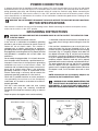
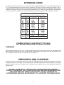
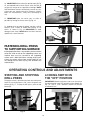
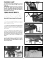
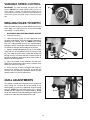
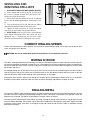
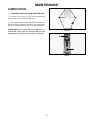
(Model DP250)
PART NO. 906771 - 07-01-02
Copyright © 2002 Delta Machinery
To learn more about DELTA MACHINERY
visit our website at: www.deltamachinery.com.
For Parts, Service, Warranty or other Assistance,
please call
ESPAÑOL: PÁGINA 17
1-800-223-7278 (In Canada call 1-800-463-3582).
INSTRUCTION MANUAL
10" Variable Speed Drill Press
GENERAL SAFETY RULES
Woodworking can be dangerous if safe and proper operating procedures are not followed. As with all machinery, there
are certain hazards involved with the operation of the product. Using the machine with respect and caution will
considerably lessen the possibility of personal injury. However, if normal safety precautions are overlooked or ignored,
personal injury to the operator may result. Safety equipment such as guards, push sticks, hold-downs, featherboards,
goggles, dust masks and hearing protection can reduce your potential for injury. But even the best guard won’t make
up for poor judgment, carelessness or inattention. Always use common sense and exercise caution in the workshop.
If a procedure feels dangerous, don’t try it. Figure out an alternative procedure that feels safer. REMEMBER: Your
personal safety is your responsibility.
This machine was designed for certain applications only. Delta Machinery strongly recommends that this machine not
be modified and/or used for any application other than that for which it was designed. If you have any questions relative
to a particular application, DO NOT use the machine until you have first contacted Delta to determine if it can or should
be performed on the product.
Technical Service Manager
Delta Machinery
4825 Highway 45 North
Jackson, TN 38305
(IN CANADA: 505 SOUTHGATE DRIVE, GUELPH, ONTARIO N1H 6M7)
WARNING: FAILURE TO FOLLOW THESE RULES MAY RESULT IN SERIOUS PERSONAL INJURY
1. FOR YOUR OWN SAFETY, READ INSTRUCTION
MANUAL BEFORE OPERATING THE TOOL. Learn the
tool’s application and limitations as well as the specific
hazards peculiar to it.
2. KEEP GUARDS IN PLACE and in working order.
3. ALWAYS WEAR EYE PROTECTION. Wear safety
glasses. Everyday eyeglasses only have impact resistant
lenses; they are not safety glasses. Also use face or dust
mask if cutting operation is dusty. These safety glasses
must conform to ANSI Z87.1 requirements. NOTE:
Approved glasses have Z87 printed or stamped on them.
4. REMOVE ADJUSTING KEYS AND WRENCHES. Form
habit of checking to see that keys and adjusting wrenches
are removed from tool before turning it “on”.
5. KEEP WORK AREA CLEAN. Cluttered areas and
benches invite accidents.
6. DON’T USE IN DANGEROUS ENVIRONMENT. Don’t
use power tools in damp or wet locations, or expose them
to rain. Keep work area well-lighted.
7. KEEP CHILDREN AND VISITORS AWAY. All children
and visitors should be kept a safe distance from work area.
8. MAKE WORKSHOP CHILDPROOF – with padlocks,
master switches, or by removing starter keys.
9. DON’T FORCE TOOL. It will do the job better and be
safer at the rate for which it was designed.
10. USE RIGHT TOOL. Don’t force tool or attachment to
do a job for which it was not designed.
11. WEAR PROPER APPAREL. No loose clothing, gloves,
neckties, rings, bracelets, or other jewelry to get caught in
moving parts. Nonslip footwear is recommended. Wear
protective hair covering to contain long hair.
12. SECURE WORK. Use clamps or a vise to hold work
when practical. It’s safer than using your hand and frees
both hands to operate tool.
13. DON’T OVERREACH. Keep proper footing and
balance at all times.
14. MAINTAIN TOOLS IN TOP CONDITION. Keep tools
sharp and clean for best and safest performance. Follow
instructions for lubricating and changing accessories.
15. DISCONNECT TOOLS before servicing and when
changing accessories such as blades, bits, cutters, etc.
16. USE RECOMMENDED ACCESSORIES. The use of
accessories and attachments not recommended by Delta
may cause hazards or risk of injury to persons.
17. REDUCE THE RISK OF UNINTENTIONAL STARTING.
Make sure switch is in “OFF” position before plugging in
power cord. In the event of a power failure, move switch
to the “OFF” position.
18. NEVER STAND ON TOOL. Serious injury could occur if
the tool is tipped or if the cutting tool is accidentally
contacted.
19. CHECK DAMAGED PARTS. Before further use of the
tool, a guard or other part that is damaged should be
carefully checked to ensure that it will operate properly and
perform its intended function – check for alignment of
moving parts, binding of moving parts, breakage of parts,
mounting, and any other conditions that may affect its
operation. A guard or other part that is damaged should be
properly repaired or replaced.
20. DIRECTION OF FEED. Feed work into a blade or
cutter against the direction of rotation of the blade or cutter
only.
21. NEVER LEAVE TOOL RUNNING UNATTENDED.
TURN POWER OFF. Don’t leave tool until it comes to a
complete stop.
22. STAY ALERT, WATCH WHAT YOU ARE DOING, AND
USE COMMON SENSE WHEN OPERATING A POWER
TOOL. DO NOT USE TOOL WHILE TIRED OR UNDER
THE INFLUENCE OF DRUGS, ALCOHOL, OR
MEDICATION. A moment of inattention while operating
power tools may result in serious personal injury.
23. MAKE SURE TOOL IS DISCONNECTED FROM
P O W E R S U P P LY w h i l e m o t o r i s b e i n g m o u n t e d ,
connected or reconnected.
24. THE DUST GENERATED by certain woods and wood
products can be injurious to your health. Always operate
machinery in well ventilated areas and provide for proper
dust removal. Use wood dust collection systems whenever
possible.
25.
WARNING: SOME DUST CREATED BY
POWER SANDING, SAWING, GRINDING, DRILLING,
AND OTHER CONSTRUCTION ACTIVITIES contains
chemicals known to cause cancer, birth defects or other
reproductive harm. Some examples of these chemicals
are:
· lead from lead-based paints,
· crystalline silica from bricks and cement and other
masonry products, and
· arsenic and chromium from chemically-treated lumber.
Your risk from these exposures varies, depending on how
often you do this type of work. To reduce your exposure
to these chemicals: work in a well ventilated area, and
work with approved safety equipment, such as those
dust masks that are specially designed to filter out
microscopic particles.
SAVE THESE INSTRUCTIONS.
Refer to them often and use them to instruct others.
2
ADDITIONAL SAFETY RULES FOR
FOR DRILL PRESSES
WARNING: FAILURE TO FOLLOW THESE RULES MAY RESULT IN SERIOUS PERSONAL INJURY.
1. DO NOT OPERATE THIS TOOL UNTIL it is
assembled and installed according to the
instructions.
14. TURN THE MACHINE “OFF” AND WAIT FOR THE
DRILL BIT, CUTTING TOOL, OR SANDER TO
STOP TURNING prior to cleaning the work area,
removing debris, removing or securing workpiece,
or changing the angle of the table. A moving drill bit,
cutting tool, or sander can be dangerous.
15 PROPERLY SUPPORT LONG OR WIDE
workpieces.
2. OBTAIN ADVICE from your supervisor, instructor,
or another qualified person if you are not familiar
with the operation of this tool.
3. FOLLOW ALL WIRING CODES and recommended
electrical connections.
16. NEVER PERFORM LAYOUT, ASSEMBLY, or setup work on the table/work area when the machine is
running.
4. NEVER START THE MACHINE BEFORE
CLEARING THE TABLE of all objects (tools, scrap
pieces, etc.).
5. NEVER START THE MACHINE with the drill bit,
cutting tool, or sander against the workpiece.
6. TIGHTEN ALL LOCK HANDLES before starting the
machine.
7. USE ONLY DRILL BITS, CUTTING TOOLS,
SANDING DRUMS, OR OTHER ACCESSORIES
that have shanks of 1/2" in diameter or less.
8. USE ONLY DRILL BITS, CUTTING TOOLS, OR
SANDING DRUMS that are not damaged.
9. PROPERLY LOCK DRILL BIT, CUTTING TOOL,
OR SANDING DRUM IN THE CHUCK before
operating this machine.
10. USE RECOMMENDED SPEEDS for all operations.
11. AVOID AWKWARD OPERATIONS AND HAND
POSITIONS where a sudden slip could cause a
hand to move into the cutting tool.
12. KEEP ARMS, HANDS, AND FINGERS away from
the cutting tool.
13. HOLD THE WORKPIECE FIRMLY AGAINST THE
TABLE. Do not attempt to drill a workpiece that
does not have a flat surface against the table.
Prevent the workpiece from rotating by clamping it
to the table or by securing it against the drill press
column.
17 TURN THE TOOL “OFF”, disconnect the tool from
the power source before installing or removing
accessories, before adjusting or changing set-ups,
or when making repairs.
18. DISCONNECT THE TOOL from the power source,
and clean the table/work area before leaving the
tool. LOCK THE SWITCH IN THE “OFF” POSITION
to prevent unauthorized use.
19. ADDITIONAL INFORMATION regarding the safe
and proper operation of this tool is available from the
Power Tool Institute, 1300 Summer Avenue,
Cleveland, OH 44115-2851. Information is also
available from the National Safety Council, 1121
Spring Lake Drive, Itasca, IL 60143-3201. Please
also refer to the American National Standards
Institute ANSI 01.1 Safety Requirements for
Woodworking Machines and the U.S. Department of
Labor OSHA 1910.213 Regulations.
SAVE THESE INSTRUCTIONS.
Refer to them often
and use them to instruct others.
3
POWER CONNECTIONS
A separate electrical circuit should be used for your machines. This circuit should not be less than #12 wire and should
be protected with a 20 Amp time lag fuse. If an extension cord is used, use only 3-wire extension cords which have 3prong grounding type plugs and matching receptacle which will accept the machine’s plug. Before connecting the
motor to the power line, make sure the switch is in the “OFF” position and be sure that the electric current is of the
same characteristics as indicated on the machine. All line connections should make good contact. Running on low
voltage will damage the motor.
WARNING: DO NOT EXPOSE THE MACHINE TO RAIN OR OPERATE THE MACHINE IN DAMP LOCATIONS.
MOTOR SPECIFICATIONS
Your machine is wired for 120 volt, 60 HZ alternating current. Before connecting the machine to the power source,
make sure the switch is in the “OFF” position.
GROUNDING INSTRUCTIONS
WARNING: THIS MACHINE MUST BE GROUNDED WHILE IN USE TO PROTECT THE OPERATOR FROM
ELECTRIC SHOCK.
1. All grounded, cord-connected machines:
2. Grounded, cord-connected machines intended for use
on a supply circuit having a nominal rating less than 150
In the event of a malfunction or breakdown, grounding
volts:
provides a path of least resistance for electric current to
reduce the risk of electric shock. This machine is
If the machine is intended for use on a circuit that has an
equipped with an electric cord having an equipmentoutlet that looks like the one illustrated in Fig. A, the
grounding conductor and a grounding plug. The plug must
machine will have a grounding plug that looks like the plug
be plugged into a matching outlet that is properly installed
illustrated in Fig. A. A temporary adapter, which looks like
and grounded in accordance with all local codes and
the adapter illustrated in Fig. B, may be used to connect
ordinances.
this plug to a matching 2-conductor receptacle as shown
in Fig. B if a properly grounded outlet is not available. The
Do not modify the plug provided - if it will not fit the outlet,
temporary adapter should be used only until a properly
have the proper outlet installed by a qualified electrician.
grounded outlet can be installed by a qualified electrician.
Improper connection of the equipment-grounding
The green-colored rigid ear, lug, and the like, extending
conductor can result in risk of electric shock. The
from the adapter must be connected to a permanent
conductor with insulation having an outer surface that is
ground such as a properly grounded outlet box. Whenever
green with or without yellow stripes is the equipmentthe adapter is used, it must be held in place with a metal
grounding conductor. If repair or replacement of the
screw.
electric cord or plug is necessary, do not connect the
equipment-grounding conductor to a live terminal.
NOTE: In Canada, the use of a temporary adapter is not
permitted by the Canadian Electric Code.
Check with a qualified electrician or service personnel if
t h e g ro u n d i n g i n s t r u c t i o n s a re n o t c o m p l e t e l y
understood, or if in doubt as to whether the machine is
WARNING: IN ALL CASES, MAKE CERTAIN THE
properly grounded.
RECEPTACLE IN QUESTION IS PROPERLY
G R O U N D E D . I F Y O U A R E N O T S U R E H AV E A
Use only 3-wire extension cords that have 3-prong
QUALIFIED ELECTRICIAN CHECK THE RECEPTACLE.
grounding type plugs and matching 3-conductor
receptacles that accept the machine’s plug, as shown in
Fig. A.
Repair or replace damaged or worn cord immediately.
GROUNDED OUTLET BOX
GROUNDED OUTLET BOX
GROUNDING
MEANS
CURRENT
CARRYING
PRONGS
ADAPTER
GROUNDING BLADE
IS LONGEST OF THE 3 BLADES
Fig. A
4
Fig. B
EXTENSION CORDS
Use proper extension cords. Make sure your extension cord is in good condition and is a 3-wire extension cord which
has a 3-prong grounding type plug and matching receptacle which will accept the machine’s plug. When using an
extension cord, be sure to use one heavy enough to carry the current of the machine. An undersized cord will cause
a drop in line voltage, resulting in loss of power and overheating. Fig. D, shows the correct gauge to use depending
on the cord length. If in doubt, use the next heavier gauge. The smaller the gauge number, the heavier the cord.
MINIMUM GAUGE EXTENSION CORD
RECOMMENDED SIZES FOR USE WITH STATIONARY ELECTRIC MACHINES
Ampere
Rating
Volts
Total Length
of Cord in Feet
Gauge of
Extension Cord
0-6
0-6
0-6
0-6
120
120
120
120
up to 25
25-50
50-100
100-150
18 AWG
16 AWG
16 AWG
14 AWG
6-10
6-10
6-10
6-10
120
120
120
120
up to 25
25-50
50-100
100-150
18 AWG
16 AWG
14 AWG
12 AWG
10-12
10-12
10-12
10-12
120
120
120
120
up to 25
25-50
50-100
100-150
16 AWG
16 AWG
14 AWG
12 AWG
12-16
12-16
12-16
120
120
120
up to 25
25-50
14 AWG
12 AWG
GREATER THAN 50 FEET NOT RECOMMENDED
Fig. D
OPERATING INSTRUCTIONS
FOREWORD
Delta ShopMaster Model DP250 is a 10", variable speed, bench drill press with a flexible work lamp. The Model DP250
allows the operator to quickly and easily change the drill speeds without removing the cover and adjusting belts. The
Delta ShopMaster Model DP250 is a valuable tool for any workshop.
UNPACKING AND CLEANING
Carefully unpack the machine and all loose items from the shipping container(s). Remove the protective coating from
all unpainted surfaces. This coating may be removed with a soft cloth moistened with kerosene (do not use acetone,
gasoline or lacquer thinner for this purpose). After cleaning, cover the unpainted surfaces with a good quality household
floor paste wax.
NOTICE: THE MANUAL COVER PHOTO ILLUSTRATES THE CURRENT
PRODUCTION MODEL. ALL OTHER ILLUSTRATIONS ARE REPRESENTATIVE
ONLY AND MAY NOT DEPICT THE ACTUAL COLOR, LABELING OR
ACCESSORIES AND MAY BE INTENDED TO ILLUSTRATE TECHNIQUE ONLY.
5
DRILL PRESS PARTS
5
1
7
6
9
8
2
3
4
10
13
11
12
Fig. 2
Fig. 1
Fig.
1 2 3 4 -
Fig. 2
5 - Chuck
6 - Clamp Handle
7 - Pinon Shaft Handles (3)
8 - Table Raising and Lowering Handle
9 - M8x1.25x125mm Carriage Head Screws (2),
8.5mm Flat Washers (2), 8.5mm Lock Washers (2),
M8x1.25 Hex Nuts (2), (for fastening the base to a
supporting surface)
10 - Worm Gear for Table Raising and Lowering Mechanism
11 - Wrenches (one 3mm and one 5mm)
12 - M8x1.25x25mm Hex Head Cap Screws (4)
13 - Chuck Key
1
Drill Press Head and Motor
Column, Base Flange, and Rack
Table
Base
6
ASSEMBLY
WARNING: FOR YOUR OWN SAFETY, DO NOT CONNECT THE MACHINE TO THE POWER SOURCE UNTIL THE
MACHINE IS COMPLETELY ASSEMBLED AND YOU READ AND UNDERSTAND THE ENTIRE INSTRUCTION
MANUAL.
1. Assemble the column (A) Fig. 3, to the base (B) using
the four screws, three of which are shown at (C). Loosen
set screw (D) and remove ring (E) and raising rack (F).
E
D
F
A
C
C
B
Fig. 3
G
2. Make certain worm gear (G) Figs. 4 and 5, is in place
in table bracket (H) as shown.
H
Fig. 4
H
G
Fig. 5
3. Insert raising rack (F) Fig. 6, which was removed in
STEP 1, into groove in table bracket making sure teeth
of worm gear (G) located inside table bracket are
engaged with teeth of raising rack (F).
F
G
7
Fig. 6
F
4. Slide raising rack (F) Fig. 7, table and table bracket
onto drill press column, as shown. Make sure bottom of
raising rack (F) Fig. 8, is inside the flange (J) on drill press
base.
Fig. 7
F
J
5. Re-assemble ring (E) Fig. 9, which was removed in
STEP 1. IMPORTANT: Bottom of ring (E) MUST NOT be
pushed all the way down onto top of raising rack (F).
MAKE SURE top of raising rack (F) is under bottom of ring
(E) and that there is enough clearance to allow rack (F) to
rotate around the column. THEN TIGHTEN SET SCREW
(D) BEING CAREFUL NOT TO OVERTIGHTEN.
Fig. 8
E
F
D
Fig. 9
G
6. Assemble table raising and lowering handle (K) Fig.
10, to worm gear shaft (G) and tighten screw (L) against
flat on shaft.
L
K
Fig. 10
8
7. Thread stud on clamp handle (M) Fig. 12, into hole in
rear of table bracket, as shown.
M
Fig. 12
N
O
8. Place the drill press head (N) Fig. 13, onto the
column as far as it will go. Align head (A) Fig. 13A, to
table (B), and base (C). Tighten the two head locking
screws (O) Fig. 13, with wrench supplied.
Fig. 13
A
B
C
Fig. 13A
9. Thread the three pinion shaft handles (P) Fig. 14, into
the three tapped holes located in the pinion shaft, as
shown.
P
Fig. 14
9
10. IMPORTANT: Make certain the spindle taper (Q) Fig.
15, and tapered hole in chuck (R) are clean and free of
any grease, lacquer or rust preventive coatings. NOTE:
Household oven cleaner can effectively remove any substance from the spindle and chuck; however, carefully
follow the manufacturer's safety rules concerning its
use.
Q
R
11. IMPORTANT: Open the chuck jaws as wide as
possible by turning the chuck sleeve (S) Fig. 16.
Fig. 15
12. Holding chuck on taper of spindle, tap with a soft tip
hammer (T) or a block of wood and hammer to set
chuck, as shown in Fig. 16. IMPORTANT: To avoid
damage to the chuck, NEVER drive the chuck onto the
spindle with a metal hammer.
S
T
Fig. 16
FASTENING DRILL PRESS
TO SUPPORTING SURFACE
If during operation there is any tendency for the machine
to tip over, slide or walk on the supporting surface, the
machine base must be secured to the supporting
surface with a M8x1.25x125mm carriage head screw,
8.5mm flat washer, 8.5mm lock washer, M8x1.25 hex
nut, through the two holes (A) Fig. 16A, located in the
machine base.
A
Fig. 16A
OPERATING CONTROLS AND ADJUSTMENTS
STARTING AND STOPPING
DRILL PRESS
LOCKING SWITCH IN
THE “OFF” POSITION
The power switch is located at the front of the drill press
head. To turn the drill press “ON”, press the green start
button (A) Fig. 17. To stop the drill press, push the red
button (B).
IMPORTANT: When the machine is not in use, the switch
should be locked in the OFF position using a padlock (C)
Fig. 18, with a 3/16" diameter shackle to prevent
unauthorized use.
C
A
B
Fig. 18
Fig. 17
10
FLEXIBLE LAMP
A
The flexible lamp operates independently of the drill
press. To turn the lamp “ON” and “OFF”, rotate switch
(A) Fig. 18A.
WARNING: To reduce the risk of fire, use 40 watt or
less, 120 volt, reflector track type light bulb (not
supplied). A standard household light bulb should not be
used. The reflector track type light bulb should not
extend below the lamp shade.
Fig. 18A
TABLE ADJUSTMENTS
1. The table can be raised or lowered on the drill press
column by loosening the table clamp (A) Fig. 19, and
turning the table raising and lowering handle (B) Fig. 20.
After the table is at the desired height, tighten clamp (A)
Fig. 19. NOTE: Final positioning of the drill press table
should always be from the bottom to the up position.
A
2. The table can be rotated 360 degrees on the column
by loosening clamp (A) Fig. 19, rotate table to desired
position and tighten clamp (A).
Fig. 19
3. The table can be tilted right or left by pulling out and
removing table alignment pin (C) Fig. 21. NOTE: If pin (C)
is difficult to remove, turn nut (E) clockwise to pull pin
out of casting.
B
4. Fig. 22, illustrates the table alignment pin (C)
removed. Loosen table locking bolt (D), tilt table to the
desired angle and tighten bolt (D). When returning table
to the level position, replace table alignment pin (C). This
will position the table surface at 90 degrees to the
spindle.
Fig. 20
5. A tilt scale (E) Fig. 23, is provided on the table
bracket casting to indicate the degree of tilt. A witness
line and zero mark (F) are also provided on the table to
line up with the scale (E).
D
E
C
Fig. 21
C
E
F
D
Fig. 23
Fig. 22
11
VARIABLE SPEED CONTROL
A
IMPORTANT: To avoid damaging the drive belts and
pulleys, DO NOT turn speed control handles (A) Fig. 24,
unless motor is running. The pilot wheel handles (A) are
turned clockwise to increase speed and counterclockwise
to decrease speed. The speed range is 500 rpm to 3100
rpm.
A
DRILLING HOLES TO DEPTH
Fig. 24
Where a number of holes are to be drilled to exactly the
same depth, the stop nut (A) Fig. 25, on the threaded
stop rod (B) is used as follows:
1. DISCONNECT MACHINE FROM POWER SOURCE.
2. Insert bit into chuck.
3. Lower the chuck (C) Fig. 25, to the depth you wish
the holes to be drilled. Then lock the quill in position by
tightening quill locking lever (E). NOTE: Quill locking
lever (E) is spring-loaded and can be repositioned by
pulling out on the handle and repositioning the hub of
the handle on the bolt located underneath the hub.
A
4. Depress spring-loaded button (F) Fig. 25, and rapidly
move stop nut (A) until bottom of nut (A) contacts stop
(G). Then hold the pinion shaft handle and loosen quill
locking lever (E), the chuck and quill will return to the up
position by gradually allowing the pinon shaft handles to
rotate to the return position.
F
G
E
C
Fig. 25
5. Place the material to be drilled on the drill press
table. Raise the drill press table until the material to be
drilled just touches the drill bit.
6. Drill a test hole to check the depth and readjust if
necessary by rotating stop nut (A) Fig. 25, for fine adjustment. It is not necessary to depress button (F) while
rotating stop nut (A) for fine adjustment.
QUILL ADJUSTMENTS
D
The spindle is raised and lowered by means of the pilot
wheel (A) Fig. 26. The quill (B) can be locked at any
desired point in its travel by tightening the quill locking
lever (C). NOTE: The quill locking lever (C) is springloaded and the handle can be repositioned by pulling
out on the handle (C) and repositioning the hub (D) of the
handle on the bolt located underneath the hub.
A
C
B
Fig. 26
12
ADJUSTING SPINDLE
RETURN SPRING
The spindle is automatically returned to its upper most
position when the handle is released. It is recommended
that the handle be allowed to slowly return to the top
position after each hole has been drilled in the material.
This spring has been properly adjusted at the factory
and should not be disturbed unless absolutely
necessary. To adjust the return spring, proceed as
follows:
1. DISCONNECT MACHINE FROM POWER SOURCE.
2. Loosen nuts (B) and (E) Fig. 27. Make sure spring
housing (A) stays engaged with head casting.
D
A
3. While FIRMLY HOLDING spring housing (A) Fig. 27
pull out housing and rotate it until boss (D) is engaged
with the next notch on the housing. Turn the housing
counterclockwise to increase or clockwise to decrease
spring tension. Turn nut (E) until it contacts spring
housing (A), then back nut (E) out a 1/4 turn from spring
housing (A). Tighten nut (B) against nut (E), to hold the
housing in place. IMPORTANT: Inside nut (E) should
not contact spring housing (A) when tightened.
E
B
Fig. 27
OPERATION
Your drill press is to be used with drill bits with a shank of 1/2" or less in diameter. The following will give the inexperienced
operator a start on common drill press operations. Use scrap material for practice to get a feel of the machine before
attempting regular work.
WARNING: The use of accessories and attachments not recommended by Delta may result in risk of injury.
IMPORTANT: When the workpiece is long enough it
should always be positioned on the table with one end
against the left side of the column, as shown in Fig. 28.
This prevents the workpiece from rotating with the drill
bit or cutting tool, causing damage to the workpiece or
personal injury to the operator. If it is not possible to
support the workpiece against the column, the
workpiece should always be fastened to the table using
clamps or a vise.
Fig. 28
13
INSTALLING AND
REMOVING DRILL BITS
C
1. DISCONNECT MACHINE FROM POWER SOURCE.
B
2. Insert smooth end of drill bit (A) Fig. 29, into chuck
(B), as far as it will go, and then back the bit out 1/16",
or up to the flutes for small bits.
A
D
3. Make certain that the drill bit (A) Fig. 29, is centered
in the chuck (B) before tightening the chuck with the key
(C).
4. Turn the chuck key (C) Fig. 29, clockwise to tighten
and counterclockwise to loosen the chuck jaws.
Fig. 29
5. Tighten all three chuck jaws to secure the drill bit
sufficiently so that it does not slip while drilling.
6. MAKE SURE chuck key (C) Fig. 29, is removed from
chuck before starting drill press. Your chuck key (C) is
equipped with a self-ejecting pin (D) which helps
minimize the hazard of the key being left in the chuck.
CORRECT DRILLING SPEEDS
Factors which determine the best speed to use are: kind of material being worked, size of hole, type of drill or other
cutter, and quality of cut desired.
WARNING: Use the recommended speed for the drill press bit and workpiece material.
BORING IN WOOD
Twist drills, although intended for metal drilling, may also be used for boring holes in wood. However, machine spur bits
are generally preferred for working in wood; they cut a flat bottom hole and are designed for removal of wood chips.
Do not use hand bits which have a screw tip; at drill press speeds they turn into the wood so rapidly as to lift the work
off the table and whirl it.
For through boring, line up the table so that the bit will enter the center hole to avoid damage to the table. Scribe a
vertical line on the front of the column and a matching mark on the table bracket and the drill press head, so that the
table and drill press head can be clamped in the center position at any height.
Feed slowly when the bit is about to cut through the wood to prevent splintering the bottom face. Use a scrap piece
of wood as a base block under the work; this helps to reduce splintering and protects the point of the bit.
DRILLING METAL
Use clamps to hold the work when drilling metal. The work should never be held in the bare hand; the drill bit may seize
the work at any time, especially when breaking through the stock. If the piece is whirled out of the operator's hand, the
operator may be injured. The drill bit will be broken if the work strikes the column.
The work must be clamped firmly while drilling; any tilting, twisting or shifting results not only in a rough hole, but also
increases drill bit breakage. For flat work, lay the piece on a wooden base and clamp it firmly down against the table
to prevent it from turning. If the piece is of irregular shape and cannot be laid flat on the table, it should be securely
blocked and clamped.
14
MAINTENANCE
LUBRICATION
1. DISCONNECT MACHINE FROM POWER SOURCE.
2. Remove the six screws (A) Fig. 30 that hold the top
cover in place, and remove the top cover.
A
A
3. The variable speed pulleys should be oiled weekly
with a few drops of light machine oil in the two oil holes
(B) Fig. 31, located on top of the variable speed pulleys.
IMPORTANT: Oil the holes when the drill press is
turned OFF. Then turn the machine ON and run
through the low and high speed ranges a few times.
Fig. 30
B
B
Fig. 31
15
ACCESSORIES
A complete line of accessories is available from your Delta Supplier, Porter-Cable • Delta Factory Service Centers,
and Delta Authorized Service Stations. Please visit our Web Site www.deltamachinery.com for a catalog or
for the name of your nearest supplier.
WARNING: Since accessories other than those offered by Delta have not been tested
with this product, use of such accessories could be hazardous. For safest operation, only
Delta recommended accessories should be used with this product.
PARTS, SERVICE OR WARRANTY ASSISTANCE
All Delta Machines and accessories are manufactured to high quality standards and are serviced by a network
of Porter-Cable • Delta Factory Service Centers and Delta Authorized Service Stations. To obtain additional
information regarding your Delta quality product or to obtain parts, service, warranty assistance, or the location
of the nearest service outlet, please call 1-800-223-7278 (In Canada call 1-800-463-3582).
Two Year Limited Warranty
Delta will repair or replace, at its expense and at its option, any Delta machine, machine part, or machine accessory which
in normal use has proven to be defective in workmanship or material, provided that the customer returns the product
prepaid to a Delta factory service center or authorized service station with proof of purchase of the product within two
years and provides Delta with reasonable opportunity to verify the alleged defect by inspection. Delta may require that
electric motors be returned prepaid to a motor manufacturer’s authorized station for inspection and repair or replacement.
Delta will not be responsible for any asserted defect which has resulted from normal wear, misuse, abuse or repair or
alteration made or specifically authorized by anyone other than an authorized Delta service facility or representative. Under
no circumstances will Delta be liable for incidental or consequential damages resulting from defective products. This
warranty is Delta’s sole warranty and sets forth the customer’s exclusive remedy, with respect to defective products; all
other warranties, express or implied, whether of merchantability, fitness for purpose, or otherwise, are expressly
disclaimed by Delta.
Printed in U.S.A.
16