1
Vykon Wireless Controller Driver Guide
Wireless Controller Driver Guide
Used With VWG-APP-1028 Wireless Card
For Vykon® JACE 2, 6 & 7® Series Product
(R1 Issue Date: July 13, 2010)
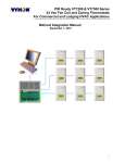
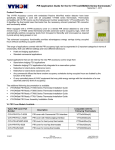
Product Overview
The VWG-APP-1028 wireless communication card and related “WirelessTstat” driver jar file have been
specifically designed to be used by Niagara AX® powered JACE controllers.
When utilized in conjunction with the Vykon wireless controllers they offer the integrator simple integration to the
Niagara AX® Workbench environment.
The application is targeted at retrofit applications where the addition of communicating field bus wiring within the
building space is prohibitive. The JACE communication card and associated Wireless Communicating Controllers
encourages the use of existing wiring utilized by existing electronic thermostat type controls.
Additional documentation is available
1
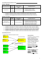
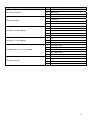
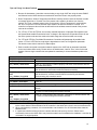
Compatibility & History Revision Table
Release 1, May 2009
Associated Jar Files
Revision
Level
Associated
Displayed Driver
Name
WirelessStat.jar
3.1.30
Main
• 2.1
• 2.1.1
• 2.1.2
WirelessStatNetwork
•
•
•
Compatible Devices
•
•
•
VT7200 Zone wireless controllers
VT7300 FCU wireless controllers
VT7600 Staging wireless controllers
Compatible VT7200 Zone wireless controllers are identified with wireless module 051-0021 Rx
Compatible VT7300 FCU wireless controllers are identified with wireless module 051-0021 Rx
Compatible VT7600 Staging wireless controllers are identified with wireless module 051-0022 Rx
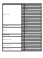
Release 2, June 2010
Associated Jar Files
WirelessTstat.jar
WirelessTstatDevices.jar
•
•
•
•
•
•
Revision
Level
4.0
Associated
Displayed Driver
Name
WirelessTstatNetwork
Compatible Devices
•
•
•
•
•
•
VT7200 Series zone wireless controllers
VT7300 Series FCU wireless controllers
VT7600 Series staging wireless controllers
VTR7300 Series FCU wireless controllers
VZ7200 Series zone wireless controllers
VZ7600 Series RTU wireless controllers
Compatible VT7200 Series zone wireless controllers are identified with wireless module 051-0083 Rx
Compatible VT7300 Series FCU wireless controllers are identified with wireless module 051-0083 Rx
Compatible VT7600 Series staging wireless controllers are identified with wireless module 051-0083 Rx
Compatible VTR7300 Series FCU wireless controllers are identified with wireless module 051-0083 Rx
Compatible VZ7200 Series zone wireless controllers are identified with wireless module 051-0070 Rx
Compatible VZ7600 Series RTU wireless controllers are identified with wireless module 051-0071 Rx
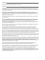
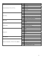
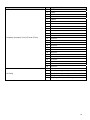
Compatibility Overview
Controller wireless communication adapter revision(s)
Release 1
Current VT72 / 73
051-0021 Rx
Jace Driver firmware(s)
Release 1
Current VT76
051-0022 Rx
Release 1 Jace-Driver
WirelessStat.Jar
WirelessTstatNetwork
Exception to the new
VTR73xx FCU Controllers
New Release 2
VT(R)72 / 73 / 76
051-0083 Rx
New Release 2
VZ72xxX
051-0070 Rx
New Release 2
VZ76xxX
051-0071 Rx
Release 2 Jace-Driver
WirelessTstat.Jar
WirelessDevices.jar
WirelessTstatNetwork
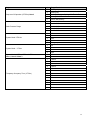
Important Notes:
The Release 2 wireless controllers
are fully compatible to the
Release 1 Jace-Driver versions.
This means that if replacement
controller parts are required on a
Release 1 installation, Release 2
controllers are compatible
Release 2 VTR7300 FCU
controllers & Zoning products
VZ72xxX / VZ76xxX are NOT
compatible to Release 1 JaceDriver versions installations
Release 1 Jace-Driver versions
installations CANNOT be
updated to the new Release 2
Jace-Driver versions as the
controllers are NOT compatible
2
Trademarks
Niagara, Niagara AX is a registered trademark of Tridium, Inc.
Disclaimers
NO WARRANTY. Vykon, Inc. (herein after referred to as “Vykon”) makes no warranty as to the accuracy of or
use of this technical documentation. Any use of the technical documentation or the information contained therein
is solely at the risk of the user.
Documentation may include technical or other inaccuracies or typographical errors. Vykon reserves the right to
make changes to this document without prior notice, and the reader should in all cases consult Vykon to
determine whether any such changes have been made. The information in this publication does not represent a
commitment on the part of Vykon.
Vykon shall not be liable for incidental or consequential damages resulting from the furnishing, performance, or
use of this material.
This guide contains links and references to third-party websites that are not under the control of Vykon, and
Vykon is not responsible for the content of any reference material or linked websites. If you access a third party
website mentioned in this guide, then you do so at your own risk. Vykon provides these links only as a
convenience, and the inclusion of the link does not imply that Vykon endorses or accepts any responsibility for
the content on those third-party sites.
Electronic controls are static sensitive devices. Discharge yourself properly before manipulation and installing
the Vykon wireless communication card.
All Vykon wireless communication cards and related wireless controllers are to be used only as operating
controls. Whenever a control failure could lead to personal injury and/or loss of property, it becomes the
responsibility of the user to add safety devices and/or alarm system to protect against such catastrophic failures.
All Vykon Series wireless controllers and associated components have been rigorously tested to ensure reliable
operation in most building applications using the latest 2.4 ZigBee technologies. Vykon cannot guarantee against
potential network interference should additional wireless systems be deployed sharing close proximity.
Best practices covered in this manual and all related Vykon documents should be considered as a guide to apply
Vykon Wireless Network devices only. The instructions included in this manual are based upon Vykon in house
testing and should be referred to as a guide only.
Vykon Inc. may not be held liable for continued reliable or robust operation of any and all wireless based devices.
Although Vykon has taken many precautions in assuring the robustness of the VT7000 series wireless controller
product line and associated network access point (JACE’s with wireless option card) please note; future
application of additional wireless devices utilizing the same or similar channels and / or frequencies may degrade
performance of overall system and / or reliability.
Non-approved modifications or changes made to the communication card, the wireless controller driver or
wireless controllers may void the FCC compliance of the wireless card and wireless controllers.
Ferrites supplied with the power supply and Vykon Wireless Communication Card shall be installed according to
instructions. Failure to do so may void the FCC compliance of the wireless card and wireless controllers.
THIS DEVICE COMPLIES WITH PART 15 OF THE FCC RULES. OPERATION IS SUBJECT TO THE
FOLLOWING TWO CONDITIONS: (1) THIS DEVICE MAY NOT CAUSE HARMFUL INTERFERENCE, AND (2)
THIS DEVICE MUST ACCEPT ANY INTERFERENCE RECEIVED, INCLUDING INTERFERENCE THAT MAY
CAUSE UNDESIRED OPERATION.
3
About Vykon Wireless Mesh Networks
The Vykon wireless card (VWG-APP-1028) and related networkable wireless controllers series operate using
ZigBee/IEEE 802.15.4 physical layer for communication.
General characteristics of the wireless physical communication layer are:
• Uses a wireless physical layer of 2.4GHz with a data rates of 250 kbps
• Yields high throughput and low latency
• Automatic multiple topologies configuration: star, peer-to-peer, mesh
• Fully handshake protocol for transfer reliability
• Range typical indoor through 4 gypsum wall partitions: 60 feet / 18M typical (up to 150 feet / 46 M based
on environment)
IEEE 802.15.4 along with ZigBee Networks and Application Support Layer provide:
• Low cost installation deployment
• Ease of implementation
• Reliable data transfer
• Short range operation
• Very low power consumption
• Appropriate levels of security
The JACE with the wireless communication card acts as network coordinator device for the IEEE
802.15.4/ZigBee network used with the wireless VYKONStats.
Many network specific features of the IEEE 802.15.4 standard are not covered in detail in this paper. However,
these are necessary for the efficient operation of a ZigBee network. These features of the network physical layer
include receiver energy detection, link quality indication and clear channel assessment. Both contention-based
and contention-free channel access methods are supported with a maximum packet size of 128 bytes, which
includes a variable payload up to 104 bytes. Also employed are 64-bit IEEE and 16-bit short addressing,
supporting over 65,000 nodes per network. All those properties of the physical layer are used and employed by
the Vykon mesh network but are hidden to the installed / user for ease of configuration and commissioning of the
network database.
A “recommended” typical maximum of:
• 30 network able controllers can be supported by a single JACE2.
• 50 network able controllers can be supported by a single JACE6.
Database creation and configuration is easily made using the Workbench environment.
The theoretical maximum of number of controllers supported by a single Jace is dependent on the resources
available for the WirelessTstatNetwork driver Jar file and the extent of integration added to the station itself.
When additional functions and services are added to the station, the available resources for the driver will be
less. Once you have configured the station for the wireless network and all other features (graphics, services,
histories, alarms, etc.), you should monitor the resources so that they do not exceed the recommended limits for
each specific platform.
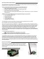
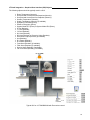
Wireless Card Installation
Please refer to the “VYKONStat Wireless Communication Card Installation
Guide” manual supplied with the VWG-APP-1028 communication card for
detailed information on the wireless communication card installation inside a
JACE controller.
Only use Com1 option slot card position for the card
4
Basic Initial Design and Deployment Consideration
IMPORTANT: It is HIGHLY recommended that you do a proper field survey with the Vykon survey tools to
establish connectivity limitations and architecture layout on ALL job sites considered for deployment with the
Vykon wireless controller products. Please refer to the following manual for the survey procedures and tool
usage: VYKONStat Wireless Survey Tool User Guide.
Please note that the following is well covered in the field survey tool procedure manual. A quick summary is
provided here as a reference.
The Vykon wireless survey tools are intended to verify and validate the deployment and use of the Vykon
wireless thermostats on a potential job site.
The survey tool will display a numerical percentage value on the LCD screen which represents the wireless
network ZigBee RSSI dBi value (Receiving Signal Strength Indicator).
•
•
Any value from 10 to 100% indicates good ZigBee connectivity.
Any value below 10% “may” indicate that an extra Router VRP 500W1028W may need to be installed.
Knowing and understanding the 6A / 5H rule of ZigBee and how to cover orphan nodes!!!
ZigBee is a standard which is suitable for wireless sensor and controller networks. In ZigBee, a device / node /
controller is said to join a network if it can obtain a ZigBee network address from a parent device. This ZigBee
address is a value which is NOT initially exposed or available for the integrator to see.
Devices / nodes / controllers can calculate and assign addresses for their surrounding devices by a distributed
address assignment scheme. This assignment is flexible, but it does somewhat restricts the number of attached
devices and the possible depth of the said network for any given device on the network.
ZigBee supports three kinds of networks type: star, tree, and mesh networks. The ZigBee coordinator ( In our
case, this is the Jace with the wireless communication card ) is responsible for initializing, maintaining, and
controlling the network.
•
•
A star network has a coordinator with devices directly connecting to the coordinator.
A tree and mesh networks, devices can communicate with each other in a multi-hop fashion.
The network is formed by one ZigBee coordinator and multiple ZigBee routers. A device can join a network as an
end device by the associating with the coordinator or a router.
A ZigBee device / node / controller is said to have successfully joined a network if it can obtain a ZigBee network
address from the main Jace coordinator or any other router devices / nodes / controller.
6A stands for a maximum 6 addresses per device / node / controller.
Any given device / node / controller including the Jace –coordinator can ONLY give a maximum 6 ZigBee
addresses out to other devices so they join the active ZigBee network. This means for any device / node /
controller to be able to successfully join a ZigBee network, it needs an address to be assigned by another device
/ node / controller which is within connectivity and that has NOT already assigned its maximum of 6 addresses
allowed.
Please note that once a device / node / controller has been assigned a ZigBee address & has joined the active
ZigBee network, it will save its assigned ZigBee address to flash memory & re-use it afterwards even after a
power failure or a network re-start. The ONLY time device / node / controller would require a NEW ZigBee
address is if the network is re-started with either a new PAN ID or a new Channel value. This causes the
currently assigned & saved ZigBee address in flash to be erased & will force the / node / controller to try to re-join
a new network.
5
Orphan Nodes.
As such it is important to understand that HOW the network is first initially started up “may” create orphan
unassigned devices / nodes / controllers that will seem to NOT want to join the ZigBee network. Let’s first
understand how an orphan node is created. A typical example is when jobs are started on a technician desk
before sending the devices / nodes / controllers in the field for installation. Often the integration technician will
power the Jace – coordinator & connect it to the Workbench tool first creating & adding the WirelessTstatNetwork
driver layer.
Once the WirelessTstatNetwork driver layer is up and running, they open & will start up the wireless devices /
nodes / controllers one by one on their desk and add them to their Niagara database.
•
•
•
They will power the first unit, add it to the database & then power it down.
They will power the second unit, add it to the database & then power it down.
And so forth up to 6 devices maximum
This will work fine for 6 devices maximum, simply because the Jace – coordinator has filled its maximum 6 give
th
away addresses. So when the technician powers up the 7 device / node / controller, it will NOT be able to join
the ZigBee network…….unless one of the previous device / node / controller is powered back on also.
In order to add another 6 devices, one of the previously added devices needs to be left on. And so forth as the
number of added devices / nodes / controllers grows. If 42 devices are to be added to the network, 8 of them
should be ALWAYS powered & within connectivity range of all the others.
So how would orphan nodes appear I the field & how would you allow them to join the ZigBee network?
Please note again that this ONLY applies to the initial network start-up & that once all the devices are online to
the Niagara database, everything will operate seamlessly even on power up / down & network re-starts.
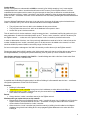
How Orphan nodes are created in the field. Ex.: 2 small buildings are within a few feet of each other. Both
have 6+ devices / nodes / controller each.
A possible case for Building B orphan nodes is as follow: Building A is first stated & sets the Jace – coordinator
configuration parameters for the PAN ID & Channel.
Premises:
• Building A is first stated.
• Yellow device / node / controller have given out its 6 addresses to other devices in building A.
• Building B devices / nodes / controllers can only be connected through blue device / nodes / controller
due to maximum distance coverage.
Result:
• Orange devices / nodes / controllers cannot join the ZigBee network.
Workaround to get orphan devices on the network:
• Disconnect & bring one of building B device / node / controller & power it up in building A until it joins the
ZigBee network ( confirmed either at the Jace – coordinator or using the status LED on the wireless
communication card of the device / node / controller.
• When the device / node / controller has joined the network in building A and is added to the Niagara
database, bring it back into building B so it can propagate ZigBee addresses to the other devices in
building B.
6
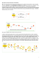
5H stands for 5 hops maximum recommended.
5H is for a simple process when laying out the architecture of the network. ANY given device / node / controller
should be “optimized” to be NO FURTHER IF POSSIBLE than 5 Hops to & from the Jace / Coordinator. This is
due to the nature of the Vykon ZigBee stack in the wireless controllers. To properly layout the potential
architecture and determine the number of Jace’s required on the job site, you first need to establish the maximum
possible coverage of a single Jace with a wireless communication card with a 5 hop maximum. This is also done
with the survey tools & is covered in detail in the manual for the survey procedures and tool usage: VYKONStat
Wireless Survey Tool User Guide.
Best practice ZigBee initial network start-up procedure
In order to avoid creating orphan devices / nodes/ controllers and moving about devices / nodes / controllers
during the initial network start-up, it is recommended that you use the same power up sequence for devices as
you originally did during the survey. Again, please note that once a device / node / controller has been assigned a
ZigBee address and has joined the active ZigBee network, it will save its assigned ZigBee address to flash
memory & re-use it afterwards even after a power failure or a network re-start. The ONLY time a device / node /
controller would require a NEW ZigBee address is if the network is re-started with either a new PAN ID or a new
Channel value. This causes the currently assigned & saved ZigBee address in flash to be erased and will force
the / node / controller to try to re-join a new network. I.E. this is ONLY applicable during the initial network startup.
7
Proper design considerations need to be addressed prior to any installation of a JACE with a Vykon
wireless communication card and related wireless controllers.
Vykon recommends using a per floor horizontal architecture vs. a vertical one. Transmitting from one floor to the
other may be possible in certain applications (such as going through stair ways), but the design and optimization
of the thermostat antenna is designed for optimal horizontal distance penetration and not a vertical one. As such,
be prepared to use AT LEAST ONE coordinator (VWG / Jace-Driver) per floor.
• Please note that radio transmissions CAN NOT travel through steel. If floors are constructed with steel joists or
other steel materials it is highly unlikely that the wireless thermostat transmissions will be successful between
floors.
1. To properly avoid network interference with 802.11 Wi-Fi devices in the 2.4GHz spectrum range, Vykon
recommends the use of 802.15.4 channels 15, 25 and 26 only. 802.11 Wi-Fi transmissions overlap and
may interfere with other channel selection allowed by 802.15.4 ( Channels 11 to 24 )
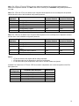
2. Maximum distance between each node ( controller ) should be:
•
Clear line of sight distance between 2 nodes should be under 100 feet ( 30 M )
8
•
Non line of sight distance for typical gypsum wall partitions made with metal stud frame should be under 30
feet ( 10M )
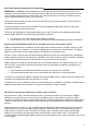
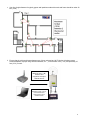
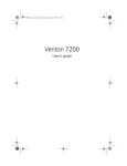
3. Ensure that the minimum distance between any Vykon node and any Wi-Fi devices (wireless routers,
wireless adapters, lap-tops using wireless networks, etc….) to be at least 3 foot ( 1 M ) and preferably 10
feet ( 3 M ) or more.
Minimum 3 feet ( 1 M )
between Wi-Fi
equipment and Vykon
wireless devices
Preferably 10 feet ( 3 M ) or
more between Wi-Fi
equipment and Vykon
wireless devices
9
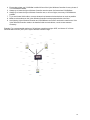
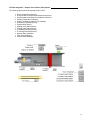
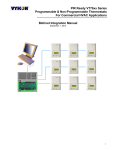
4. Ensure that at least one VYKONStat is within 30 feet of the Vykon Wireless Controller for every cluster of
10 VYKONStats installed.
5. Always try to locate the Vykon Wireless Controller near the center of all associated VYKONStats.
6. Always try to locate the Vykon Wireless Controller near, or in line of sight, to as many VYKONStats as
possible.
7. Try to avoid metal, brick walls or concrete obstructions between wireless devices as much as possible.
8. Make sure the antenna on the Vykon Wireless Controller is always perpendicular to the floor.
9. Avoid placing Vykon Wireless Controller and VYKONStats near metal or enclosed in metal boxes. If the
Vykon Wireless Controller needs to be installed inside a metal cabinet, use the remote antenna
accessory.
Example: For a recommended maximum of 30 wireless controllers total per JACE, a minimum of 3 of them
should be within 30 feet ( 9 M ) of the Vykon Wireless Controller range.
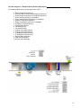
10
50 feet ( 15 M )
11
JACE and Wireless Communication Card Configuration
Initial Configuration Note: The following instructions assume you are familiar with the AX workbench
environment and its related functions:
•
Install the wireless communication card as stipulated by the instructions provided with the wireless
card
•
Copy the “WirelessTstatNetwork” and “WirelessTstatDevices” jar files to your local AX Workbench
module folder
•
Using the Software Manager, add the “WirelessTstat” jar file to the target JACE with the wireless
communication card already installed
•
Re-boot both the local AX Workbench interface and the JACE itself to properly load the
“WirelessTstatNetwork” jar modules
•
Using the “WirelessTstat” palette tool or the add network tool, simply drag & drop the
“WirelessTstatNetwork” driver under the local driver folder of the JACE
•
Rename the “WirelessTstatNetwork” driver extension name if required.
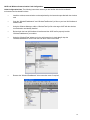
12
•
Right hand click the “WirelessTstatNetwork” driver to load the network property sheet
•
Under the Serial Port Configuration, set Port Name to “COM1”. Only COM1 can be used with the
wireless communication card since hardware flow control is required. All other properties are locked
and set as read only
•
Set the ZigBee wireless communication card options.
13
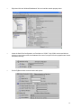
VWG ZigBee Settings
Those settings are where you set the ZigBee PAN ID (Personal Area Network Identification) address and the
channel for the wireless communication card.
• Gateway ZigBee PAN ID. (Personal Area Network Identification). This is where the PAN ID of the
gateway is set. Range is from address 1 to 500. The default of “0” is not a valid PAN ID.
• Channel Select. This is where the current Channel frequency used by the gateway is set. Range is from
11 to 26. ( 2405 MHz to 2480 MHz, 5 MHz channel spacing ) Please note that channel 26 is attenuated by
4 db compared to the other channels. The default of “10” is not a valid Channel.
• Vykon highly recommends the use of 802.15.4 channels 15, 25 and 26 only. 802.11 Wi-Fi transmissions
overlap and “may” interfere with other channel selection allowed by 802.15.4 ( Channels 11 to 14 & 16 to
24 )
• IEEE Address. Individual unique IEEE address for any ZigBee device on the network. Factory assigned &
non-editable.
• Zigbee Address. Individual unique ZigBee address for any ZigBee device on ANY INDIVIDUAL ZigBee
network. The address is assigned during the initial network start-up & saved in flash memory. This is the
main address used for all key low level network functions.
• Please note that the communication module information and the assigned IEEE & ZigBee wireless
address information are given for information references only.
• It is important to click on the “SAVE” button for the new wireless parameters to take effect and the wireless
network to properly start.
• Any time the PAN ID or Channel is changed, a new ZigBee address is assigned by the network manager
to the devices.
IMPORTANT NOTES (Please Read Carefully) :
•
Vykon recommends using a per floor horizontal architecture vs. a vertical one. Transmitting from one
floor to the other may be possible in certain applications (such as going through stair cases), but the
design and optimization of the thermostat antenna is designed for optimal horizontal distance penetration
and not a vertical one. As such, be prepared to use AT LEAST ONE coordinator (Jace-Driver) per floor.
•
Please note that radio transmissions CANNOT travel through steel. If floors are constructed with steel
joists or other steel materials it is highly unlikely that the wireless thermostat transmissions will be
successful between floors.
•
A “recommended” typical maximum of:
o 30 network able controllers can be supported by a single JACE2.
o 50 network able controllers can be supported by a single JACE6.
o Be sure you set the SAME PAN ID and Channel value at both the gateway and the controller(s).
• When properly configured, the issue of RF interference and lost data between the Jace-Driver and the
controllers can be avoided. Without proper care or proper software configuration serious interference
issues can happen.
• Again, Vykon recommends using only channels 15 & 25. Vykon recommends this purely as a
practical tip for deployment in the field based on our experience. These channels are not affected and
are out of the range of IEEE802.11x Wi-Fi Channels spectrum.
14
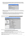
Controller Discovery & Database Tools
IMPORTANT NOTE (Please Read Carefully) :
The communication layer operates differently than “most” low level traditional wired communication bus. The
“heart” of the network resides on the wireless communication card found on the JACE. It is commonly referred to
as the “coordinator” to the network.
As such, as soon as a valid PAN ID and Channel are given to the JACE wireless communication card, any
controller having the same configuration of PAN ID and Channel can be detected and registered to the wireless
coordinator.
A discovery process is necessary to bring them to the interface and a discovery button is provided.
The “Discovered Device” folder lists the current controllers detected by the JACE that have the same PAN ID and
Channel settings as the JACE. A Yellow highlight indicates a previously discovered controller that has not
updated is mandatory wireless heartbeat to the JACE and is now offline to the JACE.
If a properly configured controller ( typically the ones furthest from the JACE ) has issues joining the network and
cannot be discovered by the JACE, a forced sync can be done by right clicking on the WirelessTstatNetwork
driver extension and selecting “ping”. Bringing it close to the JACE coordinator is another option. This will enable
it to have a Zigbee address assigned by the wireless communication card of the JACE or another controller
device. It will then enable the JACE to discover it; once discovered, re-install it at the proper location.
FOR MORE INFORMATION ON THE DISCOVERY PROCESS & GENERAL SYSTEM ARCHITECTURE,
please refer to the survey tool manual which provides more information on the subject: Rx_MAN
VST5000W5028W-Exx.
• Name. The controller’s given name in the database. The name is constructed of the controller model
number and its current local MAC address. Ex. A VT7300C5028W with a local MAC address of 21 will
carry a name in the database of VT7300C5000_21. The model name text string is fully editable as
required.
• Model. The default controller model number given in the database.
• Type. Identified for the moment which type of Vykon wireless device has been detected
• Com Address. The current physical MAC address set at each individual controller in its local
configuration.
15
• Status. Indicates if the current controller is online to the JACE or not.
o If online, the status will be {OK} and the controller line will be white
o If offline, the status will be {down} and the controller line will be yellow
• Health. The current status of each controller wireless node. “OK” is for an online controller and the date
and time represent the last time a communication event was received by the JACE from a controller. A
“Fail” represents a controller that stopped responding to its mandatory heartbeat.
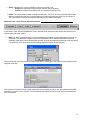
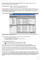
Database Tools - Add / Remove Selected Controller
At the bottom of the “WirelessTstatNetwork” folder, Add and Quick Add buttons are used to add devices to the
network along with other options.
• New. The “New” controller button is a utility that allows the integrator to create offline devices prior to the
installation. This allows the integrator to pre-build a database and all related utilities before the actual
installation takes place. When the assigned controller would be automatically discovered in the field during
commissioning, all required functions and bindings would already be done & assigned.
Select the number of devices to add of the same type and the starting local MAC address each controller will be
assigned in the field.
Then select the required controller model number that will be installed on the job site. Remember to select ALL
controllers if more than one is required. The controller can be enabled now or at a later date if the installation is
done in segments.
16
• Edit. Allows you to edit the characteristics assigned to any specific wireless controller. The controller
name, Com Address and enabled flag can be modified. The controller Model Type cannot be changed. If
another model is required under the same address, simply delete it and either create a new one offline or
re-discover the proper one.
• Match. When replacing thermostats or matching them in the field during the initial commissioning, this
feature allows you to match the characteristics of an offline created thermostat or an existing replaced one
to a newly discovered one.
• Add and Quick Add. Transfer any selected device from a “temporary” status under the discovered
window and loads them directly under the under “WirelessTstatNetwork” folder in the database window.
This will enable the controller to display all its point extensions. The add button allows you to edit the
device before it adds it to the network. Quick add is directly added to the network.
Controller Device Property Sheet
Right hand click any controller the “WirelessTstatNetwork” driver to load the controller property sheet
Status: Will give the sanity of the wireless controller to the network
o (ok) Device heartbeat reporting properly with no fault encountered
o (down) Device heartbeat failed. No communication to the device
o (fault) Transaction time out on specific object write(s). Device heartbeat is still valid
o (disabled, fault) Device has been disabled
Enabled: Enables or disables the communication to the wireless controller. It can be used if a complete database
is created for all the devices and the installation / integration is done in segments.
Health: Health status of the device. The “Last Ok Time” represents the last time the JACE received the
mandatory heartbeat from the controller.
17
Device Info, Address Info & Communication Module Info: All read only properties related to the local
controller and are given as general information.
Wireless Signal Info: CRSS - Coordinator Receiving Signal Strength ( in % )
TRSS - Thermostat Receiving Signal Strength ( in % )
These values can be known before implementing the Vykon wireless system by using the Vykon Survey Tool
(VST5000W5028W). It will determine if the area is suitable for using Vykon wireless products. Any value from 10
to 100% indicates good ZigBee connectivity. Any value below 10% “may” indicate that an extra Router VRP
5000W1028W may need to be installed.
Controller Objects Supported
Please note that the wireless objects related to any specific controller exchange present value to and from the
JACE on a fixed COV subscription base.
Back and forth from the JACE to the wireless controllers, the COV values are fixed to:
• 2.5% for PI demand Numeric objects
• 0.5 for all temperature ( C & F ) and humidity Numeric objects
• On change for all Enum’s & Boolean’s
A “recommended” typical maximum of:
• 30 network able controllers can be supported by a single JACE2.
• 50 network able controllers can be supported by a single JACE6.
The total number of controller supported is also dependent on the resources available for the
“WirelessTstatNetwork” driver Jar file and the extent of integration added to the JACE station itself.
It is safe to assume that if more advanced functions and services are added to the station, the available
resources for the driver will be less. It is important that once the station is all done and installed with all GUI,
services, trends, logs, etc…that resources are monitored and not above what is recommended by Tridium for
each specific type of JACE platform.
All objects such as GUI’s, configuration parameters and statuses will be discovered when a discovery process is
done. Afterwards, it is up to the user to pick and choose what is needed for the implementation. Therefore
by selecting only the objects needed for the required integration and discarding the other un-required objects will
consume fewer resources. I.E. All points are discovered and only the desired ones should be added to the
network.
18
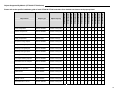
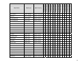
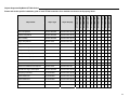
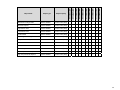
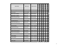
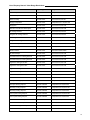
Objects Supported By Models: (VT7200 & VT7300 Series)
VT7200C5x28W
VT7200F5x28W
VT7300A5x28W
VT7305A5x28W
VT7300C5x28W
VT7305C5x28W
VT7350C5x28W
VT7355C5x28W
VT7300F5x28W
VT7305F5x28W
VT7350F5x28W
VT7355F5x28W
Please refer to the specific installation guide of each VT7200 & VT7300 controllers for a detailed overview on each property listed
Room Temperature
Numeric Writable
Present Value (R,W)
√
√
√
√
√
√
√
√
√
√
√
√
Outdoor Temperature
Numeric Writable
Present Value (R,W)
√
√
√
√
√
√
√
√
√
√
√
√
Room Humidity
Numeric Point
Present Value (R)
√
√
√
√
Supply Temperature
Numeric Point
Present Value (R)
√
√
√
√
√
√
√
√
√
√
√
√
Occupied Cooling Setpoint
Numeric Writable
Present Value (R,W)
√
√
√
√
√
√
√
√
√
√
√
√
Occupied Heating Setpoint
Numeric Writable
Present Value (R,W)
√
√
√
√
√
√
√
√
√
√
√
√
Stand-By Cooling Setpoint
Numeric Writable
Present Value (R,W)
√
√
√
√
√
√
√
√
√
√
√
√
Stand-By Heating Setpoint
Numeric Writable
Present Value (R,W)
√
√
√
√
√
√
√
√
√
√
√
√
Unoccupied Cooling Setpoint
Numeric Writable
Present Value (R,W)
√
√
√
√
√
√
√
√
√
√
√
√
Unoccupied Heating Setpoint
Numeric Writable
Present Value (R,W)
√
√
√
√
√
√
√
√
√
√
√
√
Dehumidification RH Setpoint
Numeric Writable
Present Value (R,W)
√
√
√
√
Occupancy Command
Enum Writable
Present Value (R,W)
√
√
√
√
√
√
√
√
√
√
√
√
Sequence of Operation
Enum Writable
Present Value (R,W)
√
√
√
√
√
√
√
√
√
√
√
√
System Mode
Enum Writable
Present Value (R,W)
√
√
√
√
√
√
√
√
√
√
√
√
Fan Mode
Enum Writable
Present Value (R,W)
√
√
√
√
√
√
√
√
√
√
Keypad Lockout
Enum Writable
Present Value (R,W)
√
√
√
√
√
√
√
√
√
√
Dehumidification Lockout
Boolean Writable
Present Value (R,W)
√
√
√
√
Object Name
Object Type
Object Property
√
√
19
VT7200C5x28W
VT7200F5x28W
VT7300A5x28W
VT7305A5x28W
VT7300C5x28W
VT7305C5x28W
VT7350C5x28W
VT7355C5x28W
VT7300F5x28W
VT7305F5x28W
VT7350F5x28W
VT7355F5x28W
Aux Command
Boolean Writable
Present Value (R,W)
√
√
√
√
√
√
√
√
√
√
√
√
Password
Numeric Writable
Present Value (R,W)
√
√
√
√
√
√
√
√
√
√
√
√
PI Heating Demand
Numeric Point
Present Value (R)
√
√
√
√
√
√
√
√
√
√
√
√
PI Cooling Demand
Numeric Point
Present Value (R)
√
√
√
√
√
√
√
√
√
√
√
√
Effective Occupancy
Enum Point
Present Value (R)
√
√
√
√
√
√
√
√
√
√
√
√
Dehumidification Status
Boolean Point
Present Value (R)
√
√
√
√
Fan Status
Enum Point
Present Value (R)
Aux Status
Boolean Point
Present Value (R)
√
BI1 Status
Boolean Point
Present Value (R)
BI2 Status
Boolean Point
UI3 Status
Object Name
Object Type
Object Property
√
√
√
√
√
√
√
√
√
√
√
√
√
√
√
√
√
√
√
√
√
√
√
√
√
√
√
√
√
√
√
√
√
Present Value (R)
√
√
√
√
√
√
√
√
√
√
√
√
Boolean Point
Present Value (R)
√
√
√
√
√
√
√
√
√
√
√
√
PIR Motion Status
Boolean Point
Present Value (R)
√
√
√
√
√
√
√
√
√
√
√
√
Service Alarm
Boolean Point
Present Value (R)
√
√
√
√
√
√
√
√
√
√
√
√
Filter Alarm
Boolean Point
Present Value (R)
√
√
√
√
√
√
√
√
√
√
√
√
Window Alarm
Boolean Point
Present Value (R)
√
√
√
√
√
√
√
√
√
√
√
√
Temporary Occupancy Time
Enum Writable
Present Value (R,W)
√
√
√
√
√
√
√
√
√
√
√
√
Get From
Numeric Writable
Present Value (R,W)
√
√
√
√
√
√
√
√
√
√
√
√
Deadband
Numeric Writable
Present Value (R,W)
√
√
√
√
√
√
√
√
√
√
√
√
Heating Setpoint Limit
Numeric Writable
Present Value (R,W)
√
√
√
√
√
√
√
√
√
√
√
√
Cooling Setpoint Limit
Numeric Writable
Present Value (R,W)
√
√
√
√
√
√
√
√
√
√
√
√
Display Scale
Boolean Writable
Present Value (R,W)
√
√
√
√
√
√
√
√
√
√
√
√
Menu Scroll
Boolean Writable
Present Value (R,W)
√
√
√
√
√
√
√
√
√
√
√
√
20
VT7200C5x28W
VT7200F5x28W
VT7300A5x28W
VT7305A5x28W
VT7300C5x28W
VT7305C5x28W
VT7350C5x28W
VT7355C5x28W
VT7300F5x28W
VT7305F5x28W
VT7350F5x28W
VT7355F5x28W
Room Temperature Override
Boolean Writable
Present Value (R,W)
√
√
√
√
√
√
√
√
√
√
√
√
Configuration Setpoint Type
Boolean Writable
Present Value (R,W)
√
√
√
√
√
√
√
√
√
√
√
√
Outdoor Temperature Override
Boolean Writable
Present Value (R,W)
√
√
√
√
√
√
√
√
√
√
√
√
BI1 Configuration
Enum Writable
Present Value (R,W)
√
√
√
√
√
√
√
√
√
√
√
√
BI2 Configuration
Enum Writable
Present Value (R,W)
√
√
√
√
√
√
√
√
√
√
√
√
UI3 Configuration
Enum Writable
Present Value (R,W)
√
√
√
√
√
√
√
√
√
√
√
√
Auto Mode Enable
Boolean Writable
Present Value (R,W)
√
√
√
√
√
√
√
√
√
√
Pipe Number
Enum Writable
Present Value (R,W)
√
√
√
√
√
√
√
√
√
√
Output #1 Configuration
Enum Writable
Present Value (R,W)
√
√
Aux Configuration
Enum Writable
Present Value (R,W)
√
√
√
√
√
√
√
√
√
√
√
√
Fan Mode Sequence
Enum Writable
Present Value (R,W)
√
√
√
√
√
√
√
√
√
√
Setpoint Function
Boolean Writable
Present Value (R,W)
√
√
√
√
√
√
√
√
√
√
Reheat Time Base
Boolean Writable
Present Value (R,W)
√
√
√
√
√
√
√
√
√
√
√
√
Proportional Band
Enum Writable
Present Value (R,W)
√
√
√
√
√
√
√
√
√
√
√
√
Auto Fan
Boolean Writable
Present Value (R,W)
√
√
√
√
√
√
√
√
√
√
Stand-By Time
Numeric Writable
Present Value (R,W)
√
√
√
√
√
√
√
√
√
√
√
√
Unoccupied Time
Numeric Writable
Present Value (R,W)
√
√
√
√
√
√
√
√
√
√
√
√
RH Display
Boolean Writable
Present Value (R,W)
√
√
√
√
Dehumidification Hysteresis
Numeric Writable
Present Value (R,W)
√
√
√
√
Dehumidification Max Cooling
Numeric Writable
Present Value (R,W)
√
√
√
√
Control Type
Boolean Writable
Present Value (R,W)
√
√
√
√
√
Floating Motor Timing
Enum Writable
Present Value (R,W)
√
√
√
√
√
On Off Control CPH
Enum Writable
Present Value (R,W)
√
√
√
√
√
Direct Reverse Acting
Boolean Writable
Present Value (R,W)
√
√
Object Name
Object Type
Object Property
√
√
√
21
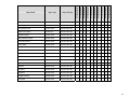
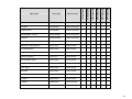
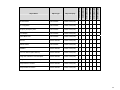
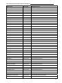
Objects Supported By Model (VT7600 Series)
VT7600A5x28W
VT7652A5x28W
VT7600B5x28W
VT7652B5x28W
VT7605B5x28W
VT7656B5x28W
VT7607B5x28W
VT7657B5x28W
VT7600H5x28W
VT7652H5x28W
Please refer to the specific installation guide of each VT7600 controllers for a detailed overview on each property listed
Room Temperature
Numeric Writable
Present Value (R,W)
√
√
√
√
√
√
√
√
√
√
Outdoor Temperature
Numeric Writable
Present Value (R,W)
√
√
√
√
√
√
√
√
√
√
Room Humidity
Numeric Writable
Present Value (R,W)
√
√
Supply Temperature
Numeric Point
Present Value (R)
√
√
Supply RH
Numeric Point
Present Value (R)
Occupied Cooling Setpoint
Numeric Writable
Present Value (R,W)
√
√
√
√
√
Occupied Heating Setpoint
Numeric Writable
Present Value (R,W)
√
√
√
√
Unoccupied Cooling Setpoint
Numeric Writable
Present Value (R,W)
√
√
√
Unoccupied Heating Setpoint
Numeric Writable
Present Value (R,W)
√
√
√
Dehumidification RH Setpoint
Numeric Writable
Humidification RH Setpoint
Object Name
Object Type
Object Property
√
√
√
√
√
√
√
√
√
√
√
√
√
√
√
√
√
√
√
√
√
√
√
√
√
√
√
√
√
√
√
√
√
Present Value (R,W)
√
√
Numeric Writable
Present Value (R,W)
√
√
Effective Humidification RH Setpoint
Numeric Point
Present Value (R)
√
√
Humidification High Limit Setpoint
Numeric Writable
Present Value (R,W)
√
√
Occupancy Command
Enum Writable
Present Value (R,W)
√
√
√
√
√
√
√
√
√
√
System Mode RTU
Enum Writable
Present Value (R,W)
√
√
√
√
√
√
√
√
System Mode HPU
Enum Writable
Present Value (R,W)
√
√
Fan Mode
Enum Writable
Present Value (R,W)
√
√
√
√
√
√
√
√
√
√
Keypad Lockout
Enum Writable
Present Value (R,W)
√
√
√
√
√
√
√
√
√
√
22
VT7600A5x28W
VT7652A5x28W
VT7600B5x28W
VT7652B5x28W
VT7605B5x28W
VT7656B5x28W
VT7607B5x28W
VT7657B5x28W
VT7600H5x28W
VT7652H5x28W
Password
Numeric Writable
Present Value (R,W)
√
√
√
√
√
√
√
√
√
√
PI Heating Demand
Numeric Point
Present Value (R)
√
√
√
√
√
√
√
√
√
√
PI Cooling Demand
Numeric Point
Present Value (R)
√
√
√
√
√
√
√
√
√
√
Effective Occupancy
Enum Point
Present Value (R)
√
√
√
√
√
√
√
√
√
√
Humidifier Output
Numeric Point
Present Value (R)
√
√
Dehumidification Status
Boolean Point
Present Value (R)
√
√
Economizer Output
Numeric Point
Present Value (R)
G Fan Status
Boolean Point
Present Value (R)
√
√
W2 Status
Boolean Point
Present Value (R)
W1 Status
Boolean Point
Present Value (R)
√
Y1 Status
Boolean Point
Present Value (R)
√
Y2 Status
Boolean Point
Present Value (R)
Reversing Valve Status
Boolean Point
Present Value (R)
Aux Status
Boolean Point
Present Value (R)
DI Status
Boolean Point
Present Value (R)
DI1 Status
Boolean Point
Present Value (R)
√
√
√
√
√
DI2 Status
Boolean Point
Present Value (R)
√
√
√
√
PIR Motion Status
Boolean Point
Present Value (R)
√
√
√
Frost Alarm
Boolean Point
Present Value (R)
√
√
√
Object Name
Object Type
Object Property
√
√
√
√
√
√
√
√
√
√
√
√
√
√
√
√
√
√
√
√
√
√
√
√
√
√
√
√
√
√
√
√
√
√
√
√
√
√
√
√
√
√
√
√
√
√
√
√
√
√
√
√
√
√
√
√
√
√
√
√
√
√
√
√
√
√
√
√
√
√
√
√
√
√
√
√
√
23
√
√
√
√
VT7652H5x28W
VT7600H5x28W
VT7657B5x28W
VT7607B5x28W
VT7656B5x28W
VT7605B5x28W
VT7652B5x28W
VT7600B5x28W
Object Property
VT7652A5x28W
Object Type
VT7600A5x28W
Object Name
√
Set Clock Alarm
Boolean Point
Present Value (R)
Service Alarm
Boolean Point
Present Value (R)
√
√
√
√
√
√
√
√
√
√
Filter Alarm
Boolean Point
Present Value (R)
√
√
√
√
√
√
√
√
√
√
Fan Lock Alarm
Boolean Point
Present Value (R)
√
√
√
√
√
√
√
√
√
√
Heating Lockout Temperature
Numeric Writable
Present Value (R,W)
√
√
√
√
√
√
√
√
√
Cooling Lockout Temperature
Numeric Writable
Present Value (R,W)
√
√
√
√
√
√
√
√
√
√
Power up Delay
Numeric Writable
Present Value (R,W)
√
√
√
√
√
√
√
√
√
√
Progressive Recovery
Boolean Writable
Present Value (R,W)
Aux Contact
Boolean Writable
Present Value (R,W)
√
√
√
√
√
√
√
√
√
√
Fan Purge Delay
Boolean Writable
Present Value (R,W)
√
√
√
√
√
√
√
√
√
√
Heating Stages
Enum Writable
Present Value (R,W)
√
√
√
√
√
√
Cooling Stages
Enum Writable
Present Value (R,W)
√
√
√
√
√
√
Heating CPH
Enum Writable
Present Value (R,W)
√
√
√
√
√
√
√
√
√
√
Cooling CPH
Enum Writable
Present Value (R,W)
√
√
√
√
√
√
√
√
√
√
Minimum On/Off Time (Anticycle)
Enum Writable
Present Value (R,W)
√
√
√
√
√
√
√
√
√
√
Temporary Occupancy Time
Enum Writable
Present Value (R,W)
√
√
√
√
√
√
√
√
√
√
Event Display
Enum Writable
Present Value (R,W)
Get From
Numeric Writable
Present Value (R,W)
√
√
√
√
√
√
√
√
√
√
Deadband
Numeric Writable
Present Value (R,W)
√
√
√
√
√
√
√
√
√
√
Heating Setpoint Limit
Numeric Writable
Present Value (R,W)
√
√
√
√
√
√
√
√
√
√
√
√
√
√
√
√
√
√
√
√
24
VT7600A5x28W
VT7652A5x28W
VT7600B5x28W
VT7652B5x28W
VT7605B5x28W
VT7656B5x28W
VT7607B5x28W
VT7657B5x28W
VT7600H5x28W
VT7652H5x28W
Cooling Setpoint Limit
Numeric Writable
Present Value (R,W)
√
√
√
√
√
√
√
√
√
√
Display Scale
Boolean Writable
Present Value (R,W)
√
√
√
√
√
√
√
√
√
√
Menu Scroll
Boolean Writable
Present Value (R,W)
√
√
√
√
√
√
√
√
√
√
Room Temperature Override
Boolean Writable
Present Value (R,W)
√
√
√
√
√
√
√
√
√
√
Outdoor Temperature Override
Boolean Writable
Present Value (R,W)
√
√
√
√
√
√
√
√
√
√
Room Humidity Override
Boolean Writable
Present Value (R,W)
√
√
Proprational Band
Enum Writable
Present Value (R,W)
√
√
√
√
√
√
√
√
√
√
Unoccupied Time
Numeric Writable
Present Value (R,W)
√
√
√
√
√
√
√
√
√
√
RH Display
Boolean Writable
Present Value (R,W)
√
√
Dehumidification Hysteresis
Numeric Writable
Present Value (R,W)
√
√
Frost Protection
Boolean Writable
Present Value (R,W)
√
√
√
√
√
√
√
√
√
√
Fan Control
Boolean Writable
Present Value (R,W)
√
√
√
√
√
√
√
√
√
√
DI Configuration
Enum Writable
Present Value (R,W)
√
√
DI1 Configuration
Enum Writable
Present Value (R,W)
√
√
√
√
√
√
√
√
DI2 Configuration
Enum Writable
Present Value (R,W)
√
√
√
√
√
√
√
√
Heatpump Stages
Enum Writable
Present Value (R,W)
√
√
Economizer Changeover Setpoint
Numeric Writable
Present Value (R,W)
√
√
Economizer Minimun Position
Numeric Writable
Present Value (R,W)
√
√
Object Name
Object Type
Object Property
25
VT7600H5x28W
VT7652H5x28W
VT7657B5x28W
VT7656B5x28W
VT7607B5x28W
VT7605B5x28W
VT7652B5x28W
VT7600B5x28W
Present Value (R,W)
√
√
Mixed Air Setpoint
Numeric Writable
Present Value (R,W)
√
√
High Balance Point
Numeric Writable
Present Value (R,W)
√
√
Low Balance Point
Numeric Writable
Present Value (R,W)
√
√
Comfort Mode
Boolean Writable
Present Value (R,W)
√
√
Reversing Valve Configuration
Boolean Writable
Present Value (R,W)
√
√
Compressor Auxiliary Lockout
Boolean Writable
Present Value (R,W)
√
√
Dehumidification Low OA Lockout
Numeric Writable
Present Value (R,W)
√
√
Dehumidification Lockout Functions
Boolean Writable
Present Value (R,W)
√
√
Low RH Setpoint
Numeric Writable
Present Value (R,W)
√
√
Low Temp Reset RH Setpoint
Numeric Writable
Present Value (R,W)
√
√
High Temp Reset RH Setpoint
Numeric Writable
Present Value (R,W)
√
√
Object Property
VT7652A5x28W
Boolean Writable
Object Type
VT7600A5x28W
Mechanical Cooling Enable
Object Name
26
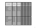
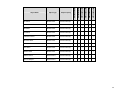
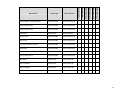
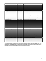
Objects Supported By Models: ( VZ7000 Zoning Products, VTR7300 Controllers and VRP5028W Wireless Repeater)
Please refer to the specific installation guide of each controller for a detailed overview on each property listed
Present Value (R,W)
√
Outdoor Temperature
Numeric Writable
Present Value (R,W)
√
Room Humidity
Numeric Point
Present Value ®
Supply Temperature
Numeric Point
Present Value ®
Occupied Cooling Setpoint
Numeric Writable
Present Value (R,W)
Occupied Heating Setpoint
Numeric Writable
Stand-By Cooling Setpoint
√
VTR7355A5x28W
Numeric Writable
VTR7350A5x28W
Room Temperature
VTR7305A5x28W
Object Property
VTR7300A5x28W
Object Type
VZ7656B5x28W
Object Name
VZ7200F5x28W
Wireless Repeater
The wireless repeater (VRP5000W1028W) has been specifically designed to be used within a Vykon wireless ZigBee network. It is intended to be a low cost additional
communication component when some remote thermostats are too far from the main mesh of Vykon devices and cannot communicate. The repeater will enable the
remote thermostats to establish communication and will act as bridges to the main mesh. Furthermore, it does not need to be added to the database network to lessen
the resource required for the Jace & the station.
√
√
√
√
√
√
√
√
√
√
√
√
√
√
√
√
√
√
√
√
√
Present Value (R,W)
√
√
√
√
√
√
Numeric Writable
Present Value (R,W)
√
√
√
√
√
Stand-By Heating Setpoint
Numeric Writable
Present Value (R,W)
√
√
√
√
√
Unoccupied Cooling Setpoint
Numeric Writable
Present Value (R,W)
√
√
√
√
√
√
Unoccupied Heating Setpoint
Numeric Writable
Present Value (R,W)
√
√
√
√
√
√
Dehumidification RH Setpoint
Numeric Writable
Present Value (R,W)
√
√
Occupancy Command
Enum Writable
Present Value (R,W)
√
√
√
√
√
√
27
VTR7300A5x28W
VTR7305A5x28W
VTR7350A5x28W
VTR7355A5x28W
Present Value (R,W)
√
√
√
√
Fan Mode
Enum Writable
Present Value (R,W)
√
√
√
√
Keypad Lockout
Enum Writable
Present Value (R,W)
√
√
√
√
Dehumidification Lockout
Boolean Writable
Present Value (R,W)
√
√
Password
Numeric Writable
Present Value (R,W)
PI Heating Demand
Numeric Point
Present Value ®
Weighted PI Heating Demand
Numeric Point
Present Value ®
PI Cooling Demand
Numeric Point
Present Value ®
Weighted PI Cooling Demand
Numeric Point
Present Value ®
√
Effective Occupancy
Enum Point
Present Value ®
√
Dehumidification Status
Boolean Point
Present Value ®
Fan Status
Enum Point
Present Value ®
G Fan Status
Boolean Point
Present Value ®
√
W2 Status
Boolean Point
Present Value ®
√
W1 Status
Boolean Point
Present Value ®
√
Y1 Status
Boolean Point
Present Value ®
√
Y2 Status
Boolean Point
Present Value (R)
√
Aux Status
Boolean Point
Present Value (R)
√
Object Property
√
VZ7656B5x28W
Enum Writable
Object Type
VZ7200F5x28W
System Mode
Object Name
√
√
√
√
√
√
√
√
√
√
√
√
√
√
√
√
√
√
√
√
√
√
√
√
√
√
√
28
VTR7300A5x28W
VTR7305A5x28W
VTR7350A5x28W
VTR7355A5x28W
Present Value (R)
BI1 Status
Boolean Point
Present Value (R)
√
√
√
√
√
BI2 Status
Boolean Point
Present Value (R)
√
√
√
√
√
UI3 Status
Boolean Point
Present Value (R)
√
PIR Motion Status
Boolean Point
Present Value (R)
√
√
√
√
Set Clock Alarm
Boolean Point
Present Value (R)
√
Service Alarm
Boolean Point
Present Value (R)
√
√
√
√
√
Filter Alarm
Boolean Point
Present Value (R)
√
√
√
√
√
Window Alarm
Boolean Point
Present Value (R)
√
√
√
√
Static Pressure
Numeric Point
Present Value (R)
√
By-Pass Damper
Numeric Point
Present Value (R)
√
Object Property
VZ7656B5x28W
Boolean Point
Object Type
VZ7200F5x28W
DI1 Status
Object Name
√
29
Heating Lockout Temperature
Numeric Writable
Present Value (R,W)
√
Cooling Lockout Temperature
Numeric Writable
Present Value (R,W)
√
Static Pressure Setpoint
Numeric Writable
Present Value (R,W)
√
Discharge High Limit Setpoint
Numeric Writable
Present Value (R,W)
√
Discharge Low Limit Setpoint
Numeric Writable
Present Value (R,W)
√
Transferred Zone PI Heating Demand
Numeric Point
Present Value (R)
√
Transferred Zone PI Cooling Demand
Numeric Point
Present Value (R)
√
Highest PI Heat Zone Mac
Numeric Point
Present Value (R)
√
Highest PI Cooling Zone Mac
Numeric Point
Present Value (R)
√
Highest PI Heating Demand
Numeric Point
Present Value (R)
√
VTR7355A5x28W
VTR7350A5x28W
VTR7305A5x28W
VTR7300A5x28W
Object Property
VZ7656B5x28W
Object Type
VZ7200F5x28W
Object Name
30
Highest PI Cooling Demand
Numeric Point
Present Value (R)
√
Power up Delay
Numeric Writable
Present Value (R,W)
√
Heating Stages Lock Status
Boolean Point
Present Value (R)
√
Cooling Stages Lock Status
Boolean Point
Present Value (R)
√
Discharge Temperature Alarm
Boolean Point
Present Value (R)
√
Local Units
Boolean Writable
Present Value (R,W)
√
Progressive Recovery
Boolean Writable
Present Value (R,W)
√
Zone Communication Lost
Boolean Point
Present Value (R)
√
Aux Contact
Boolean Writable
Present Value (R,W)
√
Fan Purge Delay
Boolean Writable
Present Value (R,W)
√
Smart Recovery Active
Boolean Point
Present Value (R)
Control Type
Enum Writable
Present Value (R,W)
√
VZ76 RTC Zone Sequence
Enum Writable
Present Value (R,W)
√
VZ72 RTC Zone Sequence
Enum Writable
Present Value (R,W)
Static Pressure Transducer Range
Enum Writable
Present Value (R,W)
√
Heating Stages
Enum Writable
Present Value (R,W)
√
Cooling Stages
Enum Writable
Present Value (R,W)
√
Heating CPH
Enum Writable
Present Value (R,W)
√
Cooling CPH
Enum Writable
Present Value (R,W)
√
√
VTR7355A5x28W
VTR7350A5x28W
VTR7305A5x28W
VTR7300A5x28W
Object Property
VZ7656B5x28W
Object Type
VZ7200F5x28W
Object Name
√
√
31
VTR7300A5x28W
VTR7305A5x28W
VTR7350A5x28W
VTR7355A5x28W
Object Property
√
√
√
√
√
√
√
√
√
√
√
√
√
√
VZ7656B5x28W
Object Type
VZ7200F5x28W
Object Name
Min On/Off Time
Enum Writable
Present Value (R,W)
√
BI1 Configuration
Enum Writable
Present Value (R,W)
√
Temporary Occupancy Time
Enum Writable
Present Value (R,W)
Event Display
Enum Writable
Present Value (R,W)
√
System Mode RTU
Enum Writable
Present Value (R,W)
√
Get From
Numeric Writable
Present Value (R,W)
√
Network Handle
Enum Writable
Present Value (R,W)
√
Deadband
Numeric Writable
Present Value (R,W)
√
RTC Com Address (MAC Address)
Numeric Writable
Present Value (R,W)
√
Config AO2 Outside Air Lockout Setpoint
Numeric Writable
Present Value (R,W)
√
Config BO5 Outside Air Lockout Setpoint
Numeric Writable
Present Value (R,W)
√
Damper Minimum Position
Numeric Writable
Present Value (R,W)
√
Damper Maximum Position
Numeric Writable
Present Value (R,W)
√
√
√
32
VTR7300A5x28W
VTR7305A5x28W
VTR7350A5x28W
VTR7355A5x28W
Present Value (R,W)
√
Heating Setpoint Limit
Numeric Writable
Present Value (R,W)
√
√
√
√
√
Cooling Setpoint Limit
Numeric Writable
Present Value (R,W)
√
√
√
√
√
AO2 Status
Numeric Point
Present Value (R)
√
Display Scale
Boolean Writable
Present Value (R,W)
√
√
√
√
√
Menu Scroll
Boolean Writable
Present Value (R,W)
√
√
√
√
√
Configuration Motion Detection
Boolean Writable
Present Value (R,W)
√
AO2 RA/DA
Boolean Writable
Present Value (R,W)
√
BO5 Time Base
Boolean Writable
Present Value (R,W)
√
BO5 Contact Function
Boolean Writable
Present Value (R,W)
√
BO5 Status
Boolean Point
Present Value (R)
√
AO2 Lock Status
Boolean Point
Present Value (R)
√
BO5 Lock Status
Boolean Point
Present Value (R)
√
Room Temperature Override
Boolean Writable
Present Value (R,W)
√
√
√
√
√
Object Property
VZ7656B5x28W
Numeric Writable
Object Type
VZ7200F5x28W
Damper Maximum Heating Position
Object Name
33
VTR7300A5x28W
VTR7305A5x28W
VTR7350A5x28W
VTR7355A5x28W
√
√
√
√
√
√
√
√
√
√
√
√
√
√
√
Present Value (R,W)
√
√
√
√
Enum Writable
Present Value (R,W)
√
√
√
√
UI3 Configuration
Enum Writable
Present Value (R,W)
√
√
√
√
Auto Mode Enable
Boolean Writable
Present Value (R,W)
√
√
√
√
Pipe Number
Enum Writable
Present Value (R,W)
√
√
√
√
Fan Mode Sequence
Enum Writable
Present Value (R,W)
√
√
√
√
Object Property
VZ7656B5x28W
√
Object Type
VZ7200F5x28W
√
Object Name
Configuration Setpoint Type
Boolean Writable
Present Value (R,W)
√
Reheat Configuration
Enum Writable
Present Value (R,W)
√
PI Heating Weight
Enum Writable
Present Value (R,W)
√
PI Cooling Weight
Enum Writable
Present Value (R,W)
√
Outdoor Temperature Override
Boolean Writable
Present Value (R,W)
√
Room Humidity Override
Boolean Writable
Present Value (R,W)
Heating Valve Status
Boolean Point
Present Value (R)
√
Cooling Valve Status
Boolean Point
Present Value (R)
BI1 Configuration
Enum Writable
BI2 Configuration
√
34
VTR7300A5x28W
VTR7305A5x28W
VTR7350A5x28W
VTR7355A5x28W
Present Value (R,W)
√
√
√
√
Proportional Band
Enum Writable
Present Value (R,W)
√
√
√
√
Auto Fan
Boolean Writable
Present Value (R,W)
√
√
√
√
Stand-By Time
Numeric Writable
Present Value (R,W)
√
√
√
√
Unoccupied Time
Numeric Writable
Present Value (R,W)
√
√
√
√
RH Display
Boolean Writable
Present Value (R,W)
√
√
Dehumidification Hysteresis
Numeric Writable
Present Value (R,W)
√
√
Dehumidification Max Cooling
Numeric Writable
Present Value (R,W)
√
√
Damper Position
Numeric Writable
Present Value (R,W)
RUI1 Configuration
Enum Writable
Present Value (R,W)
√
√
√
√
RBI2 Configuration
Enum Writable
Present Value (R,W)
√
√
√
√
RUI1 Status
Numeric Point
Present Value (R)
√
√
√
√
RBI2 Status
Boolean Point
Present Value (R)
√
√
√
√
Sequence of Operation
Enum Writable
Present Value (R,W)
√
√
√
√
Heating CPH
Enum Writable
Present Value (R,W)
√
√
√
√
Cooling CPH
Enum Writable
Present Value (R,W)
√
√
√
√
Heat No/Nc
Boolean Writable
Present Value (R,W)
√
√
√
√
Cool No/Nc
Boolean Writable
Present Value (R,W)
√
√
√
√
Pulsed Heat
Boolean Writable
Present Value (R,W)
√
√
√
√
Object Property
VZ7656B5x28W
Boolean Writable
Object Type
VZ7200F5x28W
Setpoint Function
Object Name
√
35
VTR7300A5x28W
VTR7305A5x28W
VTR7350A5x28W
VTR7355A5x28W
Present Value (R)
√
√
√
√
Wireless Window Switch Used
Boolean Point
Present Value (R)
√
√
√
√
Wireless Window Switch Status
Boolean Point
Present Value (R)
√
√
√
√
Wireless Door Switch Used
Boolean Point
Present Value (R)
√
√
√
√
Wireless Door Switch Status
Boolean Point
Present Value (R)
√
√
√
√
Heating Demand Limit
Numeric Writable
Present Value (R,W)
√
√
√
√
Cooling Demand Limit
Numeric Writable
Present Value (R,W)
√
√
√
√
PI Heating Demand
Numeric Point
Present Value (R)
√
PI Cooling Demand
Numeric Point
Present Value (R)
√
Object Property
VZ7656B5x28W
Boolean Point
Object Type
VZ7200F5x28W
Low Battery Alarm
Object Name
36
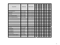
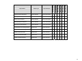
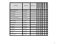
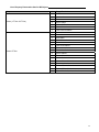
List of Property Numeric Value Range Restrictions
Object Name
Object Type
Range Restrictions
Room Temperature
Numeric Writable
temperature,min=-40,max=122
Outdoor Temperature
Numeric Writable
temperature,min=-40,max=122
Room Humidity
Numeric Point
percent,min=5,max=90
Supply Temperature
Numeric Point
temperature,min=-40,max=122
Supply RH
Numeric Point
percent,min=0,max=100
Effective Humidification RH Setpoint
Numeric Point
percent,min=0,max=100
PI Heating Demand
Numeric Point
percent,min-0,max=100
Weighted PI Heating Demand
Numeric Point
percent,min-0,max=100
PI Cooling Demand
Numeric Point
percent,min-0,max=100
Weighted PI Cooling Demand
Numeric Point
percent,min-0,max=100
Humidifier Output
Numeric Point
percent,min=0,max=100
Economizer Output
Numeric Point
percent,min=0,max=100
Static Pressure
Numeric Point
pascal,min=0,max=5000
By-Pass Damper
Numeric Point
percent,min=0,max=100
Transferred Zone PI Heating Demand
Numeric Point
percent,min=0,max=100
Transferred Zone PI Cooling Demand
Numeric Point
percent,min=0,max=100
Highest PI Heating Zone Mac
Numeric Point
percent,min=0,max=100
Highest PI Cooling Zone Mac
Numeric Point
percent,min=0,max=100
Highest PI Heating Demand
Numeric Point
percent,min=0,max=100
Highest PI Cooling Demand
Numeric Point
percent,min=0,max=100
AO2 Status
Numeric Point
percent,min=0,max=100
RUI1 Status
Numeric Point
temperature,min=-40,max=122
Occupied Cooling Setpoint
Numeric Writable
temperature,min=54,max=100
Occupied Heating Setpoint
Numeric Writable
temperature,min=40,max=90
Stand-By Cooling Setpoint
Numeric Writable
temperature,min=54,max=100
Stand-By Heating Setpoint
Numeric Writable
temperature,min=40,max=90
Unoccupied Cooling Setpoint
Numeric Writable
temperature,min=54,max=100
Unoccupied Heating Setpoint
Numeric Writable
temperature,min=40,max=90
Dehumidification RH Setpoint
Numeric Writable
percent,min=30,max=95
Humidification RH Setpoint
Numeric Writable
percent,min=10,max=90
Humidification High Limit Setpoint
Numeric Writable
percent,min=50,max=90
Password
Numeric Writable
none,min=0,max=1000
37
Object Name
Object Type
Range Restrictions
Heating Lockout Temperature
Numeric Writable
temperature,min=-15,max=120
Cooling Lockout Temperature
Numeric Writable
temperature,min=-40,max=95
Static Pressure Setpoint
Numeric Writable
pascal,min=0,max=5000
Discharge High Limit Setpoint
Numeric Writable
temperature,min=-70,max=150
Discharge Low Limit Setpoint
Numeric Writable
temperature,min=-35,max=65
Power-up Delay
Numeric Writable
seconds,min=10,max=120
Get From
Numeric Writable
none,min=0,max=254
Deadband ( VT76xx )
Numeric Writable
temperature,min=2.0,max=4.0
Deadband ( VT72 / 73xx )
Numeric Writable
temperature,min=2.0,max=5.0
RTC Communication Address
Numeric Writable
none,min=1,max=127
Config BO5 Outside Air Lockout Setpoint
Numeric Writable
temperature,min=-40,max=122
Damper Minimum Position
Numeric Writable
percent,min=0,max=100
Damper Maximum Position
Numeric Writable
percent,min=0,max=100
Damper Max Heat Position
Numeric Writable
percent,min=0,max=100
Heating Setpoint Limit
Numeric Writable
temperature,min=40,max=90
Cooling Setpoint Limit
Numeric Writable
temperature,min=54,max=100
Stand-By Time
Numeric Writable
hours,min=5.0,max=240.0
Unoccupied Time
Numeric Writable
hours,min=5.0,max=240.0
Dehumidification Hysteresis
Numeric Writable
percent,min=2,max=20
Dehumidification Max Cooling
Numeric Writable
percent,min=20,max=100
Economizer Changeover Setpoint
Numeric Writable
temperature,min=14,max=70
Economizer Minimum Position
Numeric Writable
percent,min=0,max=100
Mixed Air Setpoint
Numeric Writable
temperature,min=50,max=90
High Balance Point
Numeric Writable
temperature,min=34,max=90
Low Balance Point
Numeric Writable
temperature,min=-40,max=30
Dehumidification Low OA Lockout
Numeric Writable
temperature,min=-40,max=122
Low RH Setpoint
Numeric Writable
percent,min=10,max=90
Low Temp Reset RH Setpoint
Numeric Writable
temperature,min=-40,max=15
High Temp Reset RH Setpoint
Numeric Writable
temperature,min=20,max=55
Damper Position
Numeric Writable
percent,min=0,max=100
Heat Demand Limit
Numeric Writable
percent,min=0,max=100
Cool Demand Limit
Numeric Writable
percent,min=0,max=100
** Room Temperature, Outdoor Temperature and Room Humidity need to have their Boolean override
counterpart object set to “Override” first if the present value needs to be written over from the network. Ex To
set a network present value on the numeric “{Room Temperature” numeric object, the “Room Temperature
Override” Boolean object needs to be set from Normal to Override. The controller local present value will then be
derived from the wireless network instead of the present value at the controller.
38
List of Property Enumeration Sets for BV Objects
Object Name
Object Type
Range Restrictions
Dehumidification Status
Boolean Point
falseText=Off,trueText=On
G Fan Status
Boolean Point
falseText=Off,trueText=On
W2 Status
Boolean Point
falseText=Off,trueText=On
W1 Status
Boolean Point
falseText=Off,trueText=On
Y1 Status
Boolean Point
falseText=Off,trueText=On
Y2 Status
Boolean Point
falseText=Off,trueText=On
Reversing Valve Status
Boolean Point
falseText=Off,trueText=On
Aux Status
Boolean Point
falseText=Off,trueText=On
Aux Status
Boolean Point
falseText=Off,trueText=On
DI Status
Boolean Point
falseText=Deactivated,trueText=Activated
DI1 Status
Boolean Point
falseText=Deactivated,trueText=Activated
DI2 Status
Boolean Point
falseText=Deactivated,trueText=Activated
BI1 Status
Boolean Point
falseText=Deactivated,trueText=Activated
BI2 Status
Boolean Point
falseText=Deactivated,trueText=Activated
UI3 Status *
Boolean Point
falseText=Deactivated,trueText=Activated
PIR Motion Status
Boolean Point
falseText=No Motion,trueText=Motion
Frost Alarm
Boolean Point
falseText=Off,trueText=On
Set Clock Alarm
Boolean Point
falseText=Off,trueText=On
Service Alarm
Boolean Point
falseText=Off,trueText=On
Filter Alarm
Boolean Point
falseText=Off,trueText=On
Fan Lock Alarm
Boolean Point
falseText=Off,trueText=On
Window Alarm
Boolean Point
falseText=Off,trueText=On
Heat Stages Lockout Status
Boolean Point
falseText=Off,trueText=On
Cool Stages Lockout Status
Boolean Point
falseText=Off,trueText=On
Discharge Temperature Alarm
Boolean Point
falseText=Off,trueText=On
Comm Lost
Boolean Point
falseText=Off,trueText=On
RTC Smart Recovery Active
Boolean Point
falseText=Off,trueText=Active
BO5 Status
Boolean Point
falseText=Off,trueText=On
AO2 Lock Status
Boolean Point
falseText=Inactive,trueText=Active
BO5 Lock Status
Boolean Point
falseText=Inactive,trueText=Active
Heating Valve Status
Boolean Point
falseText=Off,trueText=On
Cooling Valve Status
Boolean Point
falseText=Off,trueText=On
RBI2 Status
Boolean Point
falseText=Off,trueText=On
Low Battery Alarm
Boolean Point
falseText=Off,trueText=On
Wireless Window Switch Used
Boolean Point
falseText=Not Used,trueText=Used
Wireless Window Switch Status
Boolean Point
falseText=Off,trueText=On
Wireless Door Switch Used
Boolean Point
falseText=Not Used,trueText=Used
Wireless Door Switch Status
Boolean Point
falseText=Off,trueText=On
39
Object Name
Object Type
Range Restrictions
Dehumidification Lockout
Boolean Writable
falseText=Disabled,trueText=Enabled
Aux Command
Boolean Writable
falseText=Off,trueText=On
Units
Boolean Writable
falseText=Imperial,trueText=SI
Progressive Recovery
Boolean Writable
falseText=Off,trueText=Active
Aux Contact
Boolean Writable
falseText=Normally Opened,trueText=Normally Closed
Fan Purge Delay
Boolean Writable
falseText=Off,trueText=On
Display Scale
Boolean Writable
falseText=C,trueText=F
Menu Scroll
Boolean Writable
falseText=No Scroll,trueText=Scroll Active
Config Motion Detection
Boolean Writable
falseText=No PIR,trueText=PIR Cover Present
AO2 RA/DA
Boolean Writable
falseText=Direct Acting,trueText=Reverse Acting
BO5 Time Base
Boolean Writable
falseText=15 Minutes,trueText=10 Seconds
BO5 Contact Function
Boolean Writable
falseText=Normally Opened,trueText=Normally Closed
Room Temperature Override
Boolean Writable
falseText=Normal,trueText=Override
Config Setpoint Type
Boolean Writable
falseText=Permanent,trueText=Temporary
Outdoor Temperature Override
Boolean Writable
falseText=Normal,trueText=Override
Room Humidity Override
Boolean Writable
falseText=Normal,trueText=Override
Auto Mode Enable
Boolean Writable
falseText=Disabled,trueText=Enabled
Setpoint Function
Boolean Writable
falseText=Dual Setpoints,trueText=Attached Setpoints
Reheat Time Base
Boolean Writable
falseText=15 Minutes,trueText=10 Seconds
Auto Fan
Boolean Writable
falseText=Auto Speed,trueText=Auto Speed / Auto Demand
RH Display
Boolean Writable
falseText=Disabled,trueText=Enabled
Control Type
Boolean Writable
falseText=On/Off,trueText=Floating
Direct Reverse Acting
Boolean Writable
falseText=Direct Acting,trueText=Reverse Acting
Fan Options
Boolean Writable
falseText=On Heat,trueText=Auto Heat
Frost Protection
Boolean Writable
falseText=Off,trueText=On
Fan Control
Boolean Writable
falseText=Off,trueText=On
Mechanical Cooling Enable
Boolean Writable
falseText=Off,trueText=On
Comfort Mode
Boolean Writable
falseText=Comfort,trueText=Economy
Reversing Valve Config
Boolean Writable
falseText=Normally Cool,trueText=Normally Heat
Comp Aux Lockout
Boolean Writable
falseText=Off,trueText=On
Dehumidification Lockout Functions
Boolean Writable
falseText=Disabled,trueText=Enabled
Heat No/Nc
Boolean Writable
falseText=Normally Closed,trueText=Normally Openend
Cool No/Nc
Boolean Writable
falseText=Normally Closed,trueText=Normally Openend
Pulsed Heat
Boolean Writable
falseText=Off,trueText=On
* This object is linked to UI3 input on all VT7200 and VT7300 series controller when used in binary mode. The
Not Activated / Activated flag status is changed upon a local contact closing on the input and will also result in
the SupplyTemp Numeric to respond from one end of its range to the other.
40
List of Property Enumeration Sets for MV Objects
Object
Alarm ( VT72xx & VT73xx )
Alarm-VT76xx
Index
Range Restrictions
1
No alarm
2
Window alarm
3
Filter alarm
4
Service alarm
5
Window & filter alarms
6
Window & service alarms
7
Filter & service alarms
1
No alarm
2
Frost alarm
3
Clock alarm
4
Clock & frost alarms
5
Filter alarm
6
Filter & frost alarms
7
Filter & clock alarms
8
Filter & frost & clock alarms
9
Service alarms
10
Service & frost alarms
11
Service & clock alarms
12
Service & frost & clock alarms
13
Filter & service alarms
14
Service & filter & frost alarms
15
Service & filter & clock alarms
16
Clock & filter & frost & service alarms
41
Object
Aux Configuration
Cooling CPH
Control Type
BI1 Config ( VT72 / VT73xx )
BI2 Config ( VT72 / VT73xx )
DI1 Config ( VT76xx )
DI2 Config ( VT76xx )
Index
Range Restrictions
1
Not Used
2
Normally Opened With Occupancy
3
Normally Closed With Occupancy
4
Normally Opened With Occupancy & Fan
5
Normally Closed With Occupancy & Fan
6
Network Controlled
1
3 CPH
2
4 CPH
1
Highest
2
Average of 3 highest
3
Average of 5 highest
1
None
2
Rem NSB
3
Motion NO
4
Motion NC
5
Window
1
None
2
Door Dry
3
Rem OVR
4
Filter
5
Service
1
None
2
Rem NSB
3
Rem OVR
4
Filter
5
Service
6
Fan Lock Alarm
1
None
2
Rem NSB
3
Rem OVR
4
Filter
5
Service
6
Fan Lock Alarm
42
Object
BI1 Config ( VZ7200X )
Effective Occupancy
Fan Mode ( VT73xx ) Note 4:
Fan Mode ( VT76xx ) Note 4:
Fan Mode Sequence ( VT73xx ) Note 4:
Fan Status (VT73xx )
Index
Range Restrictions
1
None
2
Motion NO
3
Motion NC
1
Occupied
2
Unoccupied
3
Temporary Occupied
4
Stand-by
1
Low
2
Med
3
High
4
Auto
5
On
1
On
2
Auto
3
Smart
1
Low - Med - High
2
Low - High
3
Low - Med - High - Auto
4
Low - High - Auto
5
On - Auto
1
Off
2
Low
3
Medium
4
High
43
Object
Floating Motor Timing
Heat Pump Stage
Heating CPH
Cooling Valve Status
Heating Valve Status
Keypad Lockout ( VT73xx )
Keypad Lockout ( VT72xx )
Keypad Lockout ( VT76xx )
Index
Range Restrictions
1
0.5 Minutes
2
1 Minute
3
1.5 Minutes
4
2 Minutes
5
2.5 Minutes
6
3 Minutes
7
3.5 Minutes
8
4 Minutes
9
4.5 Minutes
10
5 Minutes
11
5.5 Minutes
12
6 Minutes
13
6.5 Minutes
14
7 Minutes
15
7.5 Minutes
16
8 Minutes
17
8.5 Minutes
18
9 Minutes
1
One Stage
2
Two Stages
1
3 CPH
2
4 CPH
3
5 CPH
4
6 CPH
5
7 CPH
6
8 CPH
1
Closed
2
Opened
1
Level 0
2
Level 1
3
Level 2
4
Level 3
5
Level 4
6
Level 5
1
Level 0
2
Level 1
3
Level 2
4
Level 3
1
Level 0
2
Level 1
3
Level 2
44
Object
Minimum On/Off Time ( Anticycle )
Event Display
Heating Stages
Cooling Stages
Network Handle
Occupancy Command
On Off Control CPH
Output #1 Configuration ( VT72xx )
PI Cooling Weight
PI Heating Weight
Pipe Number
Proportional Band ( VT76xx )
Index
Range Restrictions
1
0 Minutes
2
1 Minute
3
2 Minutes
4
3 Minutes
5
4 Minutes
6
5 Minutes
1
2 Events
2
4 Events
1
1 Stage
2
2 Stages
1
Default Zone Handle
2
Default Minus Occupancy
3
Full Release
1
Local Occupancy
2
Occupied
3
Unoccupied
1
3 CPH
2
4 CPH
3
5 CPH
4
6 CPH
5
7 CPH
6
8 CPH
1
One Output
2
Separate Outputs
1
0%
2
25%
3
50%
4
75%
5
100%
1
Two Pipes
2
Four Pipes
1
3 ºF / 1.7 ºC
2
4 ºF / 2.2 ºC
3
5 ºF / 2.8 ºC
4
6 ºF / 3.3 ºC
5
7 ºF / 3.9 ºC
6
8 ºF / 4.4 ºC
7
9 ºF / 5.0 ºC
8
10 ºF / 5.6 ºC
45
Object
Proportional Band-( VT72xx & VT73xx )
RUI1 Config
RBI2 Config
Reheat Config
Reheat CPH
Zone Sequence
Sequence Of Operation ( VT73xx & VT72xx ) Note 2
Index
Range Restrictions
1
2 ºF / 1.1 ºC
2
3 ºF / 1.7 ºC
3
4 ºF / 2.2 ºC
4
5 ºF / 2.8 ºC
5
6 ºF / 3.3 ºC
6
7 ºF / 3.9 ºC
7
8 ºF / 4.4 ºC
1
None
2
Filter
3
Service
4
(COC/NH) Change over dry contact. Normally Heat
5
(COC/NC) Change over dry contact. Normally Cool
6
(COS) Change over analog sensor
1
None
2
Filter
3
Service
1
None
2
Analogue Duct Heater Only
3
On/Off Duct Heater Only
4
On/Off Peripheral Heating Only
5
Analogue Duct and On/Off Peripheral Heating
1
2 CPH
2
3 CPH
3
4 CPH
4
5 CPH
5
6 CPH
6
7 CPH
7
8 CPH
1
Cool
2
Heat
1
Cooling only
2
Heating only
3
Cooling & reheat
4
Heating & reheat
5
Cooling & heating 4 pipes
6
Cooling heating 4 pipes & reheat
46
Object
Sequence Of Operation (VTR73xx) Note 3
Static Pressure Range
System Mode-VT76Hxx
System Mode – VT76xx
System Mode – VZ72xx, VT72xx & VT73xx
Note 1, Note 2 & Note 3
Temporary Occupancy Time ( VT76xx )
Index
Range Restrictions
1
Cooling only
2
Heating only
3
Cooling / Heating or Cooling With Electric Reheat
4
Heating With Electric Reheat
5
Electric Reheat Only
1
0 to 1.5 in WC
2
0 to 2 in WC
3
0 to 3 in WC
4
0 to 4 in WC
5
0 to 5 in WC
1
Off
2
Auto
3
Cool
4
Heat
5
Emergency
1
Off
2
Auto
3
Cool
4
Heat
1
Off
2
Auto
1
0 Hours
2
1 Hour
3
2 Hours
4
3 Hours
5
4 Hours
6
5 Hours
7
6 Hours
8
7 Hours
9
8 Hours
10
9 Hours
11
10 Hours
12
11 Hours
13
12 Hours
47
Object
Temporary Occupancy Time-(VT73xx & VT72xx)
UI3 Config
Index
Range Restrictions
1
0 Hours
2
1 Hour
3
2 Hours
4
3 Hours
5
4 Hours
6
5 Hours
7
6 Hours
8
7 Hours
9
8 Hours
10
9 Hours
11
10 Hours
12
11 Hours
13
12 Hours
14
13 Hours
15
14 Hours
16
15 Hours
17
16 Hours
18
17 Hours
19
18 Hours
20
19 Hours
21
20 Hours
22
21 Hours
23
22 Hours
24
23 Hours
25
24 Hours
1
None
2
(COC/NH) Change over dry contact. Normally Heat
3
(COC/NC) Change over dry contact. Normally Cool
4
(COS) Change over analog sensor
5
(SS) Supply air sensor monitoring
48
Note 1 For VT72xx, VT73xx & VTR73xx devices, usable enumerations for the System Mode depends on
Sequence of Operation selected. The Auto mode can be used only if the AutoMode configuration parameter is
set to On.
Note 2 For VT72xx & VT73xx, the default value of System Mode depends on the Local Sequence of Operation
selected and the value of the AutoMode configuration parameter.
Sequence Of
Operation
1
2
3
4
5
6
Function
Cooling Only
Cooling with Reheat
Heating Only
Heating with Reheat
Cooling/Heating 4 Pipes
Cooling/Heating 4 Pipes with Reheat
Auto Mode
parameter Enabled
Cool
Auto
Heat
Heat
Auto
Auto
Auto Mode
parameter Disabled
Cool
Heat
Heat
Heat
Heat
Heat
Note 3 For VTR73xx, the default value of System Mode depends on the Local Sequence of Operation selected
and the value of the AutoMode configuration parameter.
Sequence Of
Operation
1
2
3
4
5
Function
Cooling only Heating only Cooling / Heating or Cooling With Electric Reheat Heating With Electric Reheat Electric Reheat Only Auto Mode
parameter Enabled
Cool
Heat
Auto
Auto Mode
parameter Disabled
Cool
Heat
Heat
Heat
Heat
Heat
Heat
Note 4:
• VT7200 do not have fan outputs and fan mode commands
• VT7300 fan mode input is dependent on local Fan Configuration
• VT7600 fan mode inputs accepted are: Auto and On. All other modes are rejected.
Available Fan modes for the VT73xx & VTR73xx controller is dependent on the local configuration of the Fan
Menu parameter
Fan Menu
Configuration
1
2
3
4
5
Fan Modes Index Accepted
1 Low - 2 Med - 3 High
1 Low - 2 High
1 Low - 2 Med - 3 High - 4 Auto
1 Low - 2 High - 3 Auto
1 Auto -2 On
Default Value
High
High
High
High
Auto
49
Integration – Global Commands
The following figure shows which typical objects from each controller attached to a VWG can be monitored and
commanded from the front-end.
Global Command Control Level
Device Level
Figure 1: Global commands from a BAS front-end to a JACE and associated controller
50
VT720xx Integration – Graphic User Interface (GUI) objects
The following objects should be typically used in a GUI:
¾
¾
¾
¾
¾
¾
¾
¾
¾
¾
¾
¾
¾
¾
Room Temperature (Numeric);
Occupied and Unoccupied Heat Setpoints (Numeric);
Occupied and Unoccupied Cool Setpoints (Numeric);
Outdoor Temperature (Numeric);
Supply Temperature (Numeric) (If available);
Occupancy Command (Enum);
System Mode (Enum);
Heating Valve Status (Enum);
Cooling Valve Status (Enum);
PI Heating Demand (Numeric)
PI Cooling Demand (Numeric)
Window Alarm (Boolean);
Filter Alarm (Boolean);
Service Alarm (Boolean);
51
VT73xxX Integration – Graphical User Interface (GUI) Objects
The following objects should be typically used in a GUI:
¾
¾
¾
¾
¾
¾
¾
¾
¾
¾
¾
¾
¾
¾
¾
¾
¾
¾
Room Temperature (Numeric);
Occupied and Unoccupied Heat Setpoints (Numeric);
Occupied and Unoccupied Cool Setpoints (Numeric);
Room Humidity (Numeric) (If available);
Room Humidity Setpoint (Numeric) (If available);
Outdoor Temperature (Numeric);
Supply Temperature (Numeric) (If available);
Occupancy Command (Enum);
System Mode (Enum);
Fan Mode (Enum);
Fan Status (Enum);
Heating Valve Status (Enum);
Cooling Valve Status (Enum);
PI Heating Demand (Numeric)
PI Cooling Demand (Numeric)
Window Alarm (Boolean);
Filter Alarm (Boolean);
Service Alarm (Boolean);
52
VT76xxX Integration – Graphical User Interface (GUI) Objects
The following objects should be typically used in a GUI:
¾
¾
¾
¾
¾
¾
¾
¾
¾
¾
¾
¾
¾
¾
¾
¾
¾
¾
¾
¾
¾
Room Temperature (Numeric);
Occupied and Unoccupied Heat Setpoints (Numeric);
Occupied and Unoccupied Cool Setpoints (Numeric);
Outdoor Temperature (Numeric);
Supply Temperature (Numeric) (If available);
Occupancy Command (Enum);
Effective Occupancy (Enum);
System Mode RTU (Enum) or System Mode HPU (Enum);
G Fan (Boolean);
Y1 Cool (Boolean);
Y2 Cool (Boolean);
W1 Heat (Boolean);
W2 Heat (Boolean) or Reversing Valve (Boolean);
Economizer Output (Numeric) (if available);
Aux (Boolean);
DI 1 Status (Boolean);
DI 2 Status (Boolean);
Frost Alarm (Boolean) (if available);
Filter Alarm (Boolean) (if available);
Service Alarm (Boolean) (if available);
Fan Lock Alarm (Boolean) (if available);
(BI 38)
(BI 25)
(BI 26)
(BI 27)
(BI 28)
(AV22)
(BI 29)
(MV 12)
(MV 14)
(BI 24)
(BI 31)
(BI 32)
(BI 36)
(BI 39)
(AV 45)
(AV 42)
(AV 43)
(AV 44)
(AV
(AI 16)
45)
(AV 45)
Typical GUI for a VT7605B5028W with Economizer control
53
Tips and Things You Need To Know
¾
Be sure all thermostats / controllers communicating to any single JACE are using the same PAN ID
and Channel as the JACE wireless communication card found & set in the property sheet.
¾
Room Temperature, Outdoor Temperature and Room Humidity need to have their Boolean override
counterpart object set to “Override” first if the present value needs to be written over from the
network. Ex To set a network present value on the numeric “{Room Temperature” numeric object,
the “Room Temperature Override” Boolean object needs to be set from Normal to Override. The
controller local present value will then be derived from the wireless network instead of the present
value at the controller.
¾
For VT72xx, VT73xx & VTR73xx, the currently selected Sequence of Operation Enumeration limits
the System Mode usable Enumeration index. A change in the Sequence Of Operation Enum will set
the active system mode and also restrict the usable range that a local controller can accept.
¾
For VT73xx & VTR73xx, Fan Mode Enumerations. Controllers will not accept all possible index
values. VT73xx & VTR73xx fan mode input is dependent on local Fan Configuration parameter.
Fan actual current value is read at Fan Status object.
¾
Each controller connected to a wireless network reports to the JACE with an automatic heartbeat
for the local online-offline sanity. Please refer to the health status “Last Ok Time” value for the total
amount of time a single controller has not updated its mandatory 3 minutes heartbeat update to the
JACE.
Jace Serial Wireless Adapter LED Status Indicators
Power on
1 x ( 200ms ) short blink
Power on and card memory initialized properly
2 x ( 200ms ) short blinks
3 x ( 200ms ) short blinks
Power on, card memory initialized properly and serial communication with the
Jace main board active
4 x ( 200ms ) short blinks
Power on, card memory initialized properly, serial communication with the Jace
main board active and wireless networks started successfully
Power on, card memory initialized properly, serial communication with the Jace
4 x ( 200ms ) short blinks
main board active, wireless networks started successfully and wireless
and
communication with controllers active
1 x ( 1500ms ) long blink
Thermostat / Controller Wireless Adapter LED Status Indicators
Power on
1 x( 200ms ) short blink
Power on and communicating with controller
2 x ( 200ms ) short blinks
3 x ( 200ms ) short blinks
Power on, communicating with controller and there is connectivity to wireless
network
4 x ( 200ms ) short blinks
Power on, communicating with controller, connectivity to wireless network and
the Jace is communicating with Wireless controller
Power on, communicating with controller, connectivity to wireless network and
4 x ( 200ms ) short blinks
the Jace is communicating with Wireless controller.
And
1 x ( 1500ms ) long blink
System Troubleshooting Recommendations
1. If a controller is not detected by a JACE, verify that the LED is blinking at least 4 times. If it is only blinking
twice, ensure that the PAN and Channel of the controller is the same as the Jace it must communicate with.
2. When commissioning a network, it is recommended to use channels 15 or 25. Alternate these channels
between floors.
3. If a particular controller refuses to join the network and cannot be seen by the Jace. Please move
momentarily closer to the JACE until it has joined the network and it is added to the database. It can then be
re-located to its original position.
54
Document Control
Document Name:
MAN Wireless Stat Driver Guide
Document Filename:
R1_MAN Wireless Tstat Driver Guide-E01.doc
Revision
01
Date
July 13, 2010
Changes
Initial release
55