1
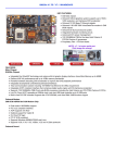
PM-9800
PENTIUM® 75MHz to 233MHz
PCI, Ultra DMA/33 & High Speed Multi I/O
Intel® 430TX Chipset System Board
User’s Guide
Revision 1.0
2
PM-9800 MAINBOARD MANUAL
MAINBOARD SPECIFICATIONS....................................................... 3
• Processor Compatibility List • Board Features
MAINBOARD DIAGRAM..................................................................... 4
• Board Layout • Glossary of Board Components
INSTALLATION GUIDE...................................................................... 5
• Step-by-Step Installation Procedures
CONNECTOR PIN CONFIGURATIONS........................................... 6
• AT Power Supply Connector • Keyboard Connector • Infrared Module
Connector • Universal Serial Bus Connector
CASE SWITCH PIN CONFIGURATIONS.......................................... 7
• Reset Switch Connector • HDD LED Connector • Suspend LED Connector
• Suspend Switch Connector • Keylock & Power LED Connector • Speaker
Connector • Case Fan Connector
MISCELLANEOUS PIN CONFIGURATIONS................................... 8
• CMOS RAM Discharge Selector • CPU Fan Connector • DIMM Voltage
Selector • CPU External Clock Selector • CPU Core Voltage Selector • CPU
Clock Multiplier Selector
CPU CONFIGURATION JUMPERS.................................................. 9
• CPU Configuration Jumpers Chart
MEMORY CONFIGURATIONS.......................................................... 10
T A B L E
O F
C O N T E N T S
• Memory Installation • Memory Considerations
ATX POWER FEATURES................................................................... 11
• ATX Power Supply Connector Pinouts • Power Switch • Modem Ring
Power-On • RTC Soft Power-On • Windows 95 Shut Down
BIOS OVERVIEW AND SPECIFICATIONS....................................... 12
• Warning • Installing a New Bios • Entering the WinBios Setup • Default
Settings
STANDARD AND ADVANCED BIOS SETTINGS............................. 13
• Primary Master & Slave, Secondary Master & Slave • Floppy Drive A & B •
1st 2nd 3rd 4th Boot Device • SMART for Hard Disks • Quick Boot • PS/2
Mouse Support • Password Check • Internal Cache • External Cache
POWER, PCI/PnP & PERIPHERAL BIOS SETTINGS.................... 14
• Power Management/APM • Green PC Monitor Power States • Video
Power Down Mode • Plug and Play Aware OS • Offboard PCI IDE Card • PCI
Slot 1/2/3/4 IRQ Priority • IRQ 4, 5, 7, 9, 10, 11, 12, 14, 15 • Onboard FDC •
Onboard Serial Port 1 & 2 • Onboard Parallel Port, Mode & IRQ • Onboard
IDE
HELPFUL HINTS AND TROUBLESHOOTING TIPS...................... 15
• What To Do First... • If You Are Still Having Problems...
Visit our website for updates: www.amptron.com
Though the information presented in this manual has been checked for accuracy and reviewed, Amptron
International Inc, assumes no responsibilities for any inaccuracies that might be in this manual nor will it be
liable for damage resulting from the use of this manual. Amptron International Inc, reserves the right to make
changes to the manual at any time and without notice.
3
PM-9800 MAINBOARD MANUAL
CPUs SUPPORTED
•Intel® Pentium® P54C (75MHz to 200MHz)
•Intel® Pentium® with MMX™ Technology P55C (166MHz to 233MHz)
•Cyrix®/IBM® 6x86MX (PR166)
•Cyrix®/IBM® 6x86L (PR166+)
•Cyrix®/IBM® 6x86 (PR120+ to PR200+)
•AMD™ K6 (PR2-166 to PR2-233)
•AMD™ K5 (PR75 to PR166)
•IDT WinChip C6™ (200MHz)
•High Performance Intel® 430TX Chipset
•Switching voltage regulator supports 3.5, 3.3, 3.2, 3.0, 2.9, 2.8 & 2.5 volt processors
MEMORY
M A I N B O A R D
S P E C I F I C A T I O N S
•Up to 256MB of main memory in 4 (2 banks) auto banking 72-pin SIMM slots for Fast
Page Mode or EDO DRAM, and 2 168-pin DIMM sockets for SDRAM, Fast Page Mode
DRAM, or EDO DRAM modules.
•Supports 64M-bit (16M X 4, 8M X 8, 4M X 16) technology DRAM/SDRAM
CACHE
•On-Board 512KB Pipeline Burst Cache
•Up to 64MB Cacheable Main Memory Size
ENHANCED IDE CONTROLLER
•Two PCI EIDE Interfaces for up to four EIDE devices in two channels. Individually supports
PIO Mode 0 to 4 and Ultra DMA/33 for all four devices - all four devices may have different
PIO modes and performance will be optimized for each device
BUS ARCHITECTURE
•Four 32-bit PCI Local Bus Slots with Master Mode
•Four 16-bit ISA Bus Slots
•Compliant to PCI 2.1
ON-BOARD I/O CONTROLLER
•On-Board Interfaces for High Speed Multi-I/Os
•Two 16550 Fast Serial Ports
•One SPP, EPP & ECP Mode Capable Parallel Port
•One High Speed Floppy Drive Connector
(Supports 2.88MB floppy drives & 1Mb/sec floppy transfer rates)
•One PS/2-type Mouse Header.
POWER MANAGEMENT FEATURES
•SMM/SMI Power Management with APM Software Interface - Monitor CPU and I/O status
with fully user configurable parameters in BIOS
•Supports following ATX power functions: Power Switch, Modem Ring-On, RTC Soft-On
•Advanced Configuration Power Interface
BIOS FEATURES
•AMI “Plug and Play” Flash ROM for easy BIOS upgrades
4
PM-9800 MAINBOARD MANUAL
E
D
F
B
C
M A I N B O A R D
D I A G R A M
A
A
ZIF SOCKET
Plug the processor into this socket.
Make sure the cpu is correctly aligned
before you insert it.
B
AT POWER SUPPLY
CONNECTOR
Plug the dual connectors from the
power supply directly into the board
connectors. On most power supplies,
you must orient the black (ground)
wires such that all the black wires on
both connectors are in the middle.
C
ATX POWER SUPPLY
CONNECTOR
Plug the single 20 pin connector into
the board connector. It should only fit
in one direction.
D
AT STYLE KEYBOARD
CONNECTOR
Plug a standard 5-pin female DIN keyboard connector into this port.
E
PS/2 MOUSE CONNECTOR
Plug a PS/2 mouse connector into
this port.
F
PS/2 MOUSE HEADER
Use this when you want to relocate
the PS/2 mouse connector plug off the
mainboard
5
PM-9800 MAINBOARD MANUAL
BE SURE YOU KNOW WHAT YOU ARE DOING!
•It’s easy to get overly excited about your purchase, and to jump right into installing the
system board into your case. Too many times, people fail to read the manual or insist on
installing it themselves, only to find out later that they’ve permanently damaged their
motherboard and as well as their components. Though this manual will make installation
seem like a fairly simple procedure, it is not. So, if you’re not a technophile or have little
or no computer knowledge, consider asking your vendor or a trained technician to install
this board.
SET SW1, SW2, SW3 TO CONFIGURE THE BOARD FOR YOUR CPU
•It’s fairly easy to forget a jumper or two, so before you power on your system, make sure
to check & double check your settings so that you don’t prematurely burn out your CPU.
INSERT THE CPU INTO THE ZIF SOCKET
•Pull up the handle and insert the CPU with the dotted corner aligned with the corner of the
ZIF socket that looks like its missing a pinhole. Plug it in and pull down on the handle.
INSTALL YOUR MEMORY INTO THE CORRECT SOCKETS
•Insert your memory into the corresponding DIMM or SIMM sockets. Follow the instructions outlined in the memory section of this manual.
INSTALL THE MAINBOARD ONTO THE SYSTEM CHASSIS
•Make sure the mainboard is properly grounded and mounted into the case. Take time to
do this properly as it makes the installation of your cards and cables easier.
CONNECT AND INSTALL YOUR CARDS & I/O CABLES
I N S T A L L A T I O N
G U I D E
•Be sure your cables and cards are properly oriented and plugged in firmly. See the helpful
hint page for tips on connecting your i/o cables.
CONNECT YOUR CASE LED & SWITCH CABLES TO THE BOARD
CONNECT THE POWER SUPPLY CABLES TO THE BOARD
•See the mainboard diagram page for tips on connecting your power cables.
POWER ON AND GO INTO BIOS AND SETUP YOUR SYSTEM
•Press <del> during memory check phase of POST and see the BIOS setup pages of this
manual for more details on setting up your system’s configuration. If you get a blank
screen, refer to the troubleshooting section for some tips on solving this problem.
GET YOUR OPERATING SYSTEM UP AND RUNNING
•Bootup your OS and see if the board and all your peripherals are recognized and working.
CLOSE UP YOUR CASE
6
PM-9800 MAINBOARD MANUAL
J2 - AT Power Supply Connector
PIN
1
2
3
4
5
6
DESCRIPTION
Power Good
+5V
+12V
-12V
Ground
Ground
PIN
7
8
9
10
11
12
DESCRIPTION
Ground
Ground
-5V
+5V
+5V
+5V
C O N F I G U R A T I O N S
J5 - Infrared Module Connector
C O N N E C T I O R
PIN
1
2
3
4
5
P I N
J3 - Keyboard Connector
DESCRIPTION
Keyboard Clock
Keyboard Data
Not Connected
Ground
+5V
J4 - PS/2 Mouse Connector
PIN
1
2
3
4
5
6
7
8
PIN
1
2
3
4
5
6
7
8
DESCRIPTION
Mouse Clock
Ground
Not Connected
Mouse Data
Not Connected
Not Connected
Not Connected
VCC
DESCRIPTION
VCC
Not Connected
IRRXL
Ground
IRTX
VCC
IRRXH
VCC
USB1 - Universal Serial Bus Connector
PIN
1
2
3
4
DESCRIPTION
+5V
DATA DATA +
Ground
Note that the pin orientations of each USB channel
(pins 1-4) are inverted in comparision with each other.
7
PM-9800 MAINBOARD MANUAL
J7 RST - Reset Switch Connector
PIN
1
2
DESCRIPTION
Signal
Ground
C A S E
S W I T C H
P I N
C O N F I G U R A T I O N S
J7 HD-LED - HDD LED Connector
PIN
1
2
DESCRIPTION
VCC
Signal
J7 SUS-LED - Suspend LED Connector
PIN
1
2
DESCRIPTION
Signal
Ground
J7 SUS-SW - Suspend Switch
PIN
1
2
DESCRIPTION
Signal
Ground
J7 KB-LOCK - Keylock & Power LED
PIN
1
2
3
4
5
DESCRIPTION
LED Output
Not Connected
Ground
Keylock
Ground
J7 SPK - Speaker Connector
PIN
1
2
3
4
DESCRIPTION
Data Out
Not Connected
Ground
+5V
JPX2 - Case Fan Connector
PIN
1
2
3
DESCRIPTION
Data
+12V
Ground
8
PM-9800 MAINBOARD MANUAL
JP1 - CMOS RAM Discharge Selector
PIN
1-2
2-3
DESCRIPTION
Normal Mode (default)
Clear CMOS
M I S C E L L A N E O U S
P I N
C O N F I G U R A T I O N S
Make sure that JP1 is set to Normal Mode (pins
1-2) before installing the mainboard.
JPX1 - CPU Fan Connector
PIN
1
2
3
DESCRIPTION
Data
+12V
Ground
JPX4 - DIMM Voltage Selector
JPX4A
1-2
2-3
JPX4B
1-2
2-3
DESCRIPTION
5V
3.3V (default)
SW1 - CPU External Clock Selector
SW1-1
ON
OFF
OFF
ON
OFF
SW1-2
ON
OFF
OFF
OFF
ON
SW1-3
ON
ON
OFF
OFF
ON
DESCRIPTION
50MHz
60MHz
66MHz
75MHz
83MHz
SW2 - CPU Core Voltage Selector
SW2-1
ON
ON
OFF
OFF
ON
OFF
OFF
ON
SW2-2
OFF
OFF
ON
OFF
ON
ON
OFF
ON
SW2-3
ON
OFF
ON
OFF
ON
OFF
ON
OFF
DESCRIPTION
2.5V
2.8V
2.9V
3.0V
3.0V
3.2V
3.3V
3.5V
SW3 - CPU Clock Multiplier Selector
SW3-1
OFF
ON
ON
OFF
OFF
ON
ON
SW3-2
OFF
OFF
ON
ON
OFF
OFF
ON
SW3-3
N/A
N/A
N/A
N/A
OFF
ON
ON
DESCRIPTION
1.5X
2.0X
2.5X
3.0X
3.5X
4.0X
4.5X
9
PM-9800 MAINBOARD MANUAL
SW1, SW2 & SW3 CPU Configuration Jumpers
CPU TYPE
CPU CLOCK
PR# MHz
C P U
C O N F I G U R A T I O N
J U M P E R S
INTEL®
PENTIUM®
P54C
INTEL®
PENTIUM®
MMX™
P55C
CYRIX®
IBM® 6x86
(3.5V)
®
®
CYRIX IBM
6x86 (L & MX)
AMD™
K5
(3.5V)
AMD™
K6
IDT WinChip™
1
SW1
2
3
1
SW2
2
3
1
SW3
2
75
ON
ON
ON
ON
ON
OFF
OFF
OFF
N/A
90
OFF
OFF
ON
ON
ON
OFF
OFF
OFF
N/A
100
OFF
OFF
OFF
ON
ON
OFF
OFF
OFF
N/A
120
OFF
OFF
ON
ON
ON
OFF
ON
OFF
N/A
133
OFF
OFF
OFF
ON
ON
OFF
ON
OFF
N/A
150
OFF
OFF
ON
ON
ON
OFF
ON
ON
N/A
166
OFF
OFF
OFF
ON
ON
OFF
ON
ON
N/A
180
OFF
OFF
ON
ON
ON
OFF
OFF
ON
N/A
200
OFF
OFF
OFF
ON
ON
OFF
OFF
ON
N/A
166
OFF
OFF
OFF
ON
OFF
OFF
ON
ON
N/A
200
OFF
OFF
OFF
ON
OFF
OFF
OFF
ON
N/A
233
OFF
OFF
OFF
ON
OFF
OFF
OFF
OFF
OFF
3
PR120+
100
ON
ON
ON
ON
ON
OFF
ON
OFF
N/A
PR150+
120
OFF
OFF
ON
ON
ON
OFF
ON
OFF
N/A
PR166+
133
OFF
OFF
OFF
ON
ON
OFF
ON
OFF
N/A
PR166+L
133
OFF
OFF
OFF
ON
OFF
OFF
ON
OFF
N/A
PR166MX
133
OFF
OFF
OFF
OFF
ON
ON
ON
OFF
N/A
PR75
75
ON
ON
ON
ON
ON
OFF
OFF
OFF
N/A
N/A
PR100
100
OFF
OFF
OFF
ON
ON
OFF
OFF
OFF
PR120
90
OFF
OFF
ON
ON
ON
OFF
OFF
OFF
N/A
PR133
100
OFF
OFF
OFF
ON
ON
OFF
OFF
OFF
N/A
PR150
150
OFF
OFF
ON
ON
ON
OFF
ON
ON
N/A
PR166
166
OFF
OFF
OFF
ON
ON
OFF
ON
ON
N/A
PR2-166
166
OFF
OFF
OFF
OFF
ON
ON
ON
ON
N/A
PR2-200
200
OFF
OFF
OFF
OFF
ON
ON
OFF
ON
N/A
PR2-233
233
OFF
OFF
OFF
OFF
ON
ON
OFF
OFF
OFF
200
OFF
OFF
OFF
ON
ON
OFF
OFF
ON
N/A
N/A MEANS THAT THE PARTICULAR JUMPER HAS NO EFFECT ON THE SETTING. IT CAN BE SET EITHER
ON “ON” OR “OFF.”
THE CYRIX 6X86 PROCESSORS CAN HAVE A SETTING OF EITHER 3.3V OR 3.5V, DEPENDING ON THE
MODEL OF THE PROCESSOR. CHECK THE PROCESSOR’S LABEL FOR MORE DETAILS.
THE CYRIX 6X86MX PROCESSOR MAY HAVE DIFFERENT CLOCK MULTIPLIER SETTINGS, DEPENDING
ON THE MODEL OF THE PROCESSOR. CHECK THE PROCESSOR’S LABEL FOR MORE DETAILS.
10
PM-9800 MAINBOARD MANUAL
MEMORY INSTALLATION
BANK#
0
DESCRIPTION
SIMM1 & SIMM2
(72 PIN SIMM) OR
DIMM2
(168 PIN DIMM)
MEMORY MODULE
2 X 4MB / 8MB / 16MB / 32MB / 64MB
OR
4MB / 8MB / 16MB / 32MB /
64MB / 128MB
1
DIMM1
(168 PIN DIMM)
4MB / 8MB / 16MB / 32MB /
64MB / 128MB
2
SIMM3 & SIMM4
(72 PIN SIMM)
2 X 4MB / 8MB / 16MB / 32MB / 64MB
M E M O R Y
C O N F I G U R A T I O N S
MEMORY CONSIDERATIONS
•The mainboard lets you add up to 256MB of system memory through 4 SIMM and 2 DIMM
sockets on the board
•Each bank consists of two 72-pin SIMM modules, or a 168-pin DIMM module.
•You cannot install memory into SIMM1 & SIMM2 and DIMM2 sockets at the same time
•The speed of all SIMMs and DIMM modules have to be faster than 70ns
•Uses Fast Page Mode or Externded DATA Out (EDO) for the SIMM sockets
•Uses Fast Page Mode, Extended DATA Out (EDO) or Synchronous DRAM (SDRAM) for
the DIMM sockets.
•The function of Bank 2 will not be available for use when using 64M-bit type of SDRAM in
any DIMM slot.
11
PM-9800 MAINBOARD MANUAL
The functions that described in this chapter will not be available unless the ATX power
connector is being used.
J1 - ATX Power Supply Connector
A T X
P O W E R
F E A T U R E S
PIN
1
2
3
4
5
6
7
8
9
10
11
12
13
14
15
16
17
18
19
20
DESCRIPTION
3.3V
3.3V
Ground
+5V
Ground
+5V
Ground
Power OK
5VSB
+12V
3.3V
-12V
Ground
PS-On
Ground
Ground
Ground
-5V
+5V
+5V
JP2 (POW SW) - POWER SWITCH
•When the system is off, push the power button to turn the system on.
•When the system is on, push the power button rapidly to switch the system to the
Suspend mode and by pushing and holding the button for more than 4 seconds, it will turn
the system completely off.
•When the system is in the Suspend mode, push the power button rapidly to turn the
system on.
MODEM RING POWER-ON
•While in soft-off/suspend state, if an external modem ring-up signal occurs, the system
wakes up and can be remotely accessed.
•Make sure that the Resume On Ring option is set to ENABLED in the BIOS setup section
(Refer to the Power Management section in Chapter 4).
RTC SOFT POWER-ON
•If you want to auto boot the system at a certain time, set the function of RTC Alarm time
properly and the function of RTC Alarm Resume From Soft-Off option in the BIOS Setup
section will be set to ENABLED.
WINDOWS 95 SHUT DOWN
•If ATX Power is used, the “It is now safe to turn off your computer” message will not be
shown when you are shutting down the computer.
12
PM-9800 MAINBOARD MANUAL
After you have configured the mainboard and have assembled the components, turn on the
computer and run the software setup to ensure that the systems information is correct.
B I O S
O V E R V I E W
A N D
S P E C I F I C A T I O N S
WARNING
•Due to the frequent upgrades of the AMI WINBIOS, this manual may not include descriptions of all the features available to you in your current BIOS.
•Do not change the settings in the BIOS unless you know EXACTLY what you are doing or
when told to do so by a trained technician. Changing any of the BIOS settings, may affect
the performance of your system and can also cause your system to hang.
INSTALLING A NEW BIOS
•When installing a new BIOS into this mainboard, JP1 must be set to the clear CMOS
position for a moment. Replace the jumper back to the normal position before flashing the
bios. You can also hold down the <END> key and then power on to clear the CMOS.
ENTERING THE WINBIOS SETUP
•When the computer is POSTing during bootup (going through a series of diagnostic checks),
hit the <DEL> key when prompted to enter the BIOS setup screen.
DEFAULT SETTINGS
•There are three default values for the BIOS:
Original - The original default values recover the modified settings to the original settings.
Optimal - The optimal default values provide the optimum settings for all devices and system features.
Best - The best default values provide the best performance settings for all devices and
system features but it may cause your system to be unstable.
13
PM-9800 MAINBOARD MANUAL
PRIMARY MASTER & SLAVE, SECONDARY MASTER & SLAVE
A D V A N C E D
B I O S
S E T T I N G S
•Choose these icons to configure the hard disk drive named in the option. When you click
on an icon, the following parameters are listed: Type, LBA/Large Mode, Block Mode, 32-bit
Mode and PIO Mode. All parameters relate to IDE drives except Type
FLOPPY DRIVE A,B
•Choose the Floppy Drive A or B icon to specify the floppy drive type. The settings are
360KB 51/4”, 1.2MB 51/4”, 720KB 31/2”, 1.44MB 31/2” or 2.88MB 31/2”.
1ST, 2ND, 3RD, 4TH BOOT DEVICE
•Set these options to select the boot sequence from different booting devices.
SMART FOR HARD DISKS
•This allows you to enable or disable the SMART function of hard drives.
QUICK BOOT
•When this option is set to ENABLED, the BIOS skips many of the POST diagnostic
steps so that bootup is faster.
PS/2 MOUSE SUPPORT
•When this option is set to ENABLED, the BIOS supports a PS/2 type mouse.
PASSWORD CHECK
•This option specifies the type of BIOS password protection that is implemented. The
settings are:
Setup - The password prompt appears only when an enduser attempts to run BIOS setup.
Always - A password prompt appears every time the computer is powered on or rebooted.
•The BIOS password does not have to be enabled. The enduser sets the password by
choosing the password icon on the BIOS setup screen.
INTERNAL CACHE
S T A N D A R D
A N D
•Set this option to ENABLED to enable the Internal CPU cache.
EXTERNAL CACHE
•Set this option to ENABLED to enable the external L2 cache.
14
PM-9800 MAINBOARD MANUAL
POWER MANAGEMENT/APM
•Set this option to ENABLED to enable power management and APM features.
•This option specifies the power state that the green PC compliant video monitor enters
when BIOS places it in a power saving state after the specified period of display inactivity
has expired.
VIDEO POWER DOWN MODE
•This option specifies the power conserving state that the VESA VGA video subsystem
enters after the specified period of display inactivity has expired.
HARD DISK POWER DOWN MODE
•This option specifies the power conserving state that the hard disk drive enters after the
specified period of hard drive inactivity has expired.
PLUG AND PLAY AWARE OS
•Set this option to YES if the operating system in this computer is PnP-aware.
OFFBOARD PCI IDE CARD
•This option specifies if an offboard PCI IDE controller adapter card is installed in the
computer. You must specify the PCI expansion slot on the motherboard where the offboard
PCI IDE controller is installed. This disables the onboard PCI IDE controller. You must
also specify the IRQs for this PCI IDE card.
PCI SLOT 1/2/3/4 IRQ PRIORITY
•These options specify the priority IRQ to be used for any PCI devices installed in PCI
expansion slots 1 through 4.
&
P E R I P H E R A L
S E T T I N G S
GREEN PC MONITOR POWER STATES
P C I / P n P
IRQ 4, 5, 7, 9, 10, 11, 12, 14, 15
•These options allow you to reserve IRQs for legacy (non-PnP) ISA adapter cards.
ONBOARD FDC
•This option allows you to enabled the floppy drive controller on the motherboard.
ONBOARD SERIAL PORT 1 & 2
•This option specifies the base I/O port address of serial port 1 & 2
P O W E R ,
ONBOARD PARALLEL PORT, MODE, & IRQ
•This option specifies the base I/O port address, type (Normal, Bi-Dir, EPP or EPP/ECP),
and IRQ of the parallel port on the motherboard.
ONBOARD IDE
•This option specifies the channel used by the IDE controller on the motherboard.
15
PM-9800 MAINBOARD MANUAL
H E L P F U L
H I N T S
A N D
T R O U B L E S H O O T I N G
T I P S
WHAT TO DO FIRST...
•The most overlooked and common problems are actually the easiest to solve. Even if you
are the most seasoned of all computer technophiles and you can tell Bill Gates a thing or
two, make sure you double check the following three most frequently repeated mistakes:
(1) The power cable is not plugged firmly into the power supply in the back of the computer.
Or the motherboard is not connected to the power supply.
(2) You’ve got ide, floppy, serial, parallel, scsi cables that are either not plugged in firmly
into the respective ports or they are plugged in “backwards.”
(3) Your jumpers for the cpu bus speed, clock multiplier, or voltage are not properly configured.
IF YOU STILL ARE HAVING PROBLEMS...
•The best way to solve any of your computer problems is to "start all over again." You've
probably accumulated many peripherals every since you've got your computer. So basically remove all your cards except for the video card and your hard drive controller (if you
have a SCSI hard drive or if you don't have an on-board i/o controller) and reboot your
system.
•If you still get error messages after this reboot, try booting in "safe" mode per Windows 95
or try configurating your system with the most basic drivers i.e. vga instead of svga etc. If
your problem is resolved, then it is most likely not a motherboard problem and the source
of the crashes is due to one of your cards. See the next paragraph for suggestions on how
to solve these problems. If the problem is not resolved then check your bios and reset the
CMOS to factory defaults. You do this by hitting the specific hotkey (del or some other
key prompted for when you boot up) during the memory check period of "bootup." Then
select the function of resetting CMOS to factory defaults. Exit, save changes, and it will
reboot. Other things that you can try if this doesn't help is to check the configuration of the
motherboard and making sure the jumpers correctly match the components you've put on
it i.e. cpu type and clock speed, type and size of cache etc. check your manual for what
the correct jumper settings are. You can also check your memory, by booting your system with the minimal number of memory chips (1 for 486/5x86, 2 for Pentiums) and
rotating them and rebooting after each rotation to see if you can successfully restart your
system. You can also try turning off your external cache via your bios and seeing if that is
the problem.
•Basically, the best technique for troubleshooting is to change one setting and then rebooting,
until you can get it to work.
•Once you're at this step you need to place one of your other cards in, one at a time and
reboot after each installation of the card and its specific drivers. Do this until all your cards
are in or until your system crashes or freezes again. If it crashes, then you will know that
it has to do with that card. So "start all over again" by taking out all cards except for the
video card and your hard drive controller and placing that particular card with the problem
into your system. If it works then, it is probably a compatibility or configuration problem
between two or more of your cards, so go back and check their IRQs, DMAs, I/O addresses, and make sure to contact the manufacturer for the latest drivers and ask for their
tech support.
•Most problems with your computer can be traced to factors other than your motherboard
and it is simply a matter of getting the right drivers or configurations from your peripheral
manufacturer and you'll be on the right track in no time.
Trademark Acknowledgment
Pentium is a trademark of the Intel Corporation.
AMI is a trademark of American Megatrends Inc.
MS-DOS, Windows 95 are trademarks of the Microsoft Corporation.
Other trademarks belong to their respective owners.
Specifications are subject to change without notice.
Though the information presented in this User’s Guide has been
reviewed carefully, no responsibility is assumed for inaccuracies.
Published & Printed in the United States