1
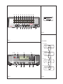
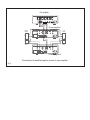
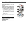
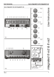
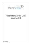
a b c d e f g h i 1)
-27
Balance
OUT
IN
MCBUS
PRE OUT 1 PRE OUT 2
ZONE 2
OUT
HEADPHONE
MADE IN ENGLAND
1*
IN-6
IN-5
IN-4
IN-3
IN-2
IN-1
USE PSX-R ONLY
IN-7
IN-8
IN-9
IN-10
IN-11
1& 1^ 1% 1$ 1# 1@
1!
Fig 3
Fig 1
MC-BUS
Cyrus amplifier
MC-BUS out
MC-BUS in
Cyrus CD player
ab
c
d
e
MC-BUS out
MC-BUS in
-27
CD
Sample rate 44.1kHz
Cyrus Tuner
MC-BUS out
INPUT
MUTE
PHONES
ZONE 2
MC-BUS in
SETUP
Cyrus Power Amplifier
1)
i
h
g
f
MC-BUS out
MC-BUS in
Fig 2
Fig 4
Pre-amplifier
L
L
PRE 1
PRE 2
R
TP OUT
TP2 IN
L
TP1 IN
R
AU2
AU1
AV
TU
CD
R
Power amplifier 1
Right
treble
-
-
+
+
+
+
-
Left
treble
-
Right
bass
Left
bass
Power amplifier 2
Connecting a bi-amplified speaker system to a pre-amplifier
Fig 5
Cyrus Pre XPd, Cyrus Pre XPd Qx
User Instructions
IMPORTANT! Read before operating this equipment!
NAKED FLAMES: No naked flame sources, such as candles, must be placed
on this product. Batteries (battery pack or batteries installed) shall not be
exposed to excessive heat such as sunshine, fire or the like.
LIGHTNING: For added protection for this product during a lightning storm, or
when it is left unattended or unused for long periods of time, unplug it from the
wall outlet and disconnect the antenna or cable system. This will prevent
damage to the product due to lightning and power-line surges.
CAUTION: The exclamation mark is to draw your attention to
important instructions and safety procedures in this manual.
ATTENTION: The lightning flash warns you of the risk of
electrical shock presented by components inside this product.
Unauthorised personnel must not open this unit.
BATTERIES: Warning : Batteries shall not be exposed to excessive heat
such as sunshine, fire or the like.
CAUTION! POLARISED CONNECTOR (CANADA and USA):
To prevent electrical shock, match wide blade of plug to wide slot, fully insert.
Do not alter or remove this plug if it does not fit your mains power socket.
Have a suitable socket installed by a competent electrician.
WARNING: To reduce the risk of electrical shock do not remove any unit
covers or panels. There are no user serviceable parts in this product.
WARNING: To reduce the risk of electric shock, do not expose this
equipment to rain or moisture.
HEED WARNINGS: All warnings on the product and in the operating
instructions should be adhered to.
READ ALL THE INSTRUCTIONS: All the safety and operating instructions
should be read before the product is operated.
POWER SUPPLY: (Refer to Fig.1)
Connect the moulded IEC connector of the AC cord supplied plugs into the
power inlet 1* on the rear of the unit.
The mains supply requirement of your amplifier is marked on a label on the
rear panel. Before connecting, check that this voltage is the same as your
mains supply.
RETAIN INSTRUCTIONS: The safety and operating instructions should be
retained for future reference.
FOLLOW INSTRUCTIONS: All operating and use instructions should be
followed.
CLEANING: Unplug this product from the mains before cleaning. Do not use
liquid or aerosol cleaners. Use a damp cloth for cleaning.
WATER AND MOISTURE: Do not use this product near water - for example,
near a bath tub, wash bowl, kitchen sink, or laundry tub, in a wet basement; or
near a swimming pool and the like. The product must not be exposed to
dripping or splashing and no objects filled with liquids, such as vases, shall be
placed on the product.
HEAT: The product should be situated away from heat sources such as
radiators, stoves, or any other products (including amplifiers) that produce
heat.
VENTILATION: Slots and openings in the cabinet are provided for ventilation,
to ensure reliable operation of the product and to protect it from overheating
and these openings must not be blocked or covered. The openings should
never be blocked by placing the product on a bed, sofa, rug or similar surface.
This product should not be placed in a built-in installation such as a bookcase
or rack unless proper ventilation is provided or the manufacturer's instructions
have been adhered to.
OBJECT OR LIQUID ENTRY: Never push objects of any kind into this
product through openings as they may touch dangerous voltage points or
short-out parts that could result in a fire or electric shock.
ACCESSORIES: Do not place this product on an unstable cart, stand, tripod,
bracket, or table. The product may fall, causing serious injury to a child or
adult, and serious damage to the product. Use only with a cart, stand, tripod,
bracket or table recommended by the manufacturer, or sold with the product.
Any mounting of the product should follow the manufacturer's instructions,
and should use a mounting accessory recommended by the manufacturer.
230V Products:
Voltage Range
220V-240V
115V Products:
Voltage Range
110V-120V
If you move to an area with a different mains voltage, contact your local Cyrus
distributor to have your product converted.
There are no user replaceable fuses in this unit.
SERVICING:
Do not attempt to service this product yourself as opening or removing covers
may expose you to dangerous voltage or other hazards. Refer all servicing to
qualified service personnel.
CONDITIONS REQUIRING SERVICE: Unplug this product from the wall
outlet and refer servicing to qualified service personnel when:
•
•
•
•
•
When the power supply cord or plug is damaged.
If liquid has been spilled, or objects have fallen into the product.
If the product has been exposed to rain or water.
If the product has been dropped or damaged in any way.
If the product does not operate normally by following the operating
instructions. (Adjust only those controls that are covered by the
operating instructions. Improper adjustment of other controls may
result in damage requiring extensive work by a qualified technician
to restore the product to its normal operation).
•
When the product exhibits a distinct change in performance.
REPLACEMENT PARTS: When replacement parts are required, be sure the
service technician has used replacements specified by the manufacturer or
have the same characteristics as the original part. Unauthorised substitutions
may result in fire, electric shock, or other hazards.
SAFETY CHECK: Upon completion of any service or repairs to this product,
ask the service technician to perform safety checks to determine that the
product is in proper operating condition.
ATTACHMENTS: Do not use attachments not recommended by the product
manufacturer as they may cause hazards.
MOVING THE PRODUCT: A product and cart combination
should be moved with care. Sudden stops, excessive force,
and uneven surfaces may cause the product and cart to
overturn.
POWER SOURCES: This product should be operated only from the type of
power source indicated on the marking label. If you are not sure of the type of
power supply to your home, consult your product dealer or local power
company. For products intended to operate from battery power, or other
sources, refer to the operating instructions.
OVERLOADING: Never overload wall outlets, extension cords, or integral
convenience receptacles. This can result in an increased risk of fire or electric
shock.
POWER CORD PROTECTION: Power supply cords should be routed so that
they are not likely to be walked on or pinched by items placed upon or against
them, paying particular attention to cords at plugs, convenience receptacles,
and the point where they exit from the product.
PRODUCT SERVICE CENTRES
For product service or technical advice, contact only authorised Cyrus service
centres. Contact details for Cyrus distributors may be found on the Cyrus
website at www.cyrusaudio.com.
1
Cyrus Pre XPd, Cyrus Pre XPd Qx
User Instructions
Welcome to the world of Cyrus!
INSTALLATION (Refer to Fig 1):
Congratulations on your choice of Cyrus Hi-fi products. Our state-of-the-art
design technology and outstanding quality of manufacture has won countless
awards around the world. We are confident that you will derive great pleasure
from owning a product from one of the most recognised and respected
manufacturers of hi-fi equipment.
Now is a good time to register your new Cyrus product. Registration takes
only a few minutes, brings the added benefit of a full two year factory warranty
and adds you to our mailing list for future product updates and upgrades. To
register, visit www.cyrusaudio.com and click the ‘Login/Register’ link.
Please read these instructions carefully before commencing installation. They
provide full guidance to help you install your amplifier safely and correctly.
Key to the rear panel drawings:
1.
2.
3.
4.
5.
6.
7.
8.
9.
Preparations for Installation
10.
11.
12.
13.
14.
15.
16.
17.
18.
Analogue Input 1
PSX-R Connection
Digital Input 11 (USB)
Digital Input 10
Digital Input 9
Digital Input 8
Digital Input 7
Headphone Socket
Power Inlet
Connecting to the AC Mains Supply
Before installing your Cyrus pre-amplifier check that the following items are
included in the accessory box.
•
MC-BUS System Connection
Pre-Amplifier Output
Pre-Amplifier Output
Zone 2 (& tape) Output
Analogue Input 6
Analogue Input 5
Analogue Input 4
Analogue Input 3
Analogue Input 2
Connect the socket on the AC Power cable to the Power inlet 1* on the rear panel
of the amplifier. Now connect the cable to a suitable AC power point.
NOTE: The means to disconnect this product from the mains supply is the
mains plug. Ensure that the mains plug is accessible at all times.
Power Cable
• Remote Handset
• 2 x cables for MC-BUS connection
After removing these items, please retain the packaging.
Install the amplifier in a well ventilated location away from sources of high
temperature, dust or humidity. Never stand the amplifier under another unit or
on any surface likely to obstruct its cooling or ventilation.
IMPORTANT NOTE – READ BEFORE MAKING ANY
AUDIO CONNECTIONS
To avoid possible damage to your amplifier, it is essential to disconnect all
system components from the mains supply before connecting or
disconnecting audio interconnects.
Connecting Analogue Audio Sources
Analogue Inputs 1-6 are available for the connection of stereo analogue audio
sources including •
Analogue output from CD/DVD Players
•
Analogue output from DAB or FM Radio tuners
•
Phono pre-amplifier for a turntable
•
Televisions
•
Analogue Satellite Receivers
•
Analogue Tape/Disc recorders
•
Cyrus surround decoder
The factory set input names for some of the inputs are pre-set as follows Input 1 – CD
Input 2 – Tuner
Input 3 – Cyrus AV (for a Cyrus AV surround processor)
Input 6 – Tape
All inputs may be re-named, but for convenience you may prefer to connect
these sources to the pre-named inputs.
Analogue Input 6 is recommended for connection of Tape Recorders. This
input is not selectable for recording purposes to avoid howl-round with Tape
Recorders, nor is it available to play in a Zone 2 system.
To connect an Analogue Audio source to your amplifier, connect a stereo
audio interconnect cable between each component and the sockets as
marked on the rear panel. Ensure left and right channels are correctly
connected. Make a note of the input number used for each source as the
inputs can be re-named at the set-up stage.
Connecting a Turntable
To play a turntable through your unit an external phono pre-amplifier is
required. This may then be connected to one of the Analogue inputs.
2
Cyrus Pre XPd, Cyrus Pre XPd Qx
User Instructions
Digital Audio Inputs
Connecting a Tape/Disc recorder for recording
Connecting digital audio sources
The digital audio inputs are compatible with a number of different digital audio
sources. These include•
PC or MAC computer via a USB cable
•
Digital Audio output from a CD player
•
Digital Radio
•
DVD players (for replay of 2 channel PCM programs only)
•
Digital Satellite receivers (for replay of 2 channel PCM programs only)
•
Digital tape/disc recorders
Using a suitable Toslink optical or Digital phono interconnect, connect each
digital audio source to one of the inputs 7-10. Make a note of the input
number used for each source as the inputs can be re-named at the set-up
stage.
Connecting USB audio sources
The USB audio input 11 may be used to connect the audio feed from a
computer. Using a suitable USB cable, connect the USB output from the
computer to the USB input 1@.
NOTE: The USB Audio input is configured for USB slave operation and is not
suitable for connection of USB drives or other flash media.
When not in use for a Zone 2 system, the dual-purpose output Zone 2/Tape
may be used to connect a tape recorder for recording purposes. To set up a
tape recording loop, connect a phono cable from the ‘Input’ or ‘Record’
sockets of the tape deck to the Zone 2 Output d sockets.
NOTE: This section assumes that the ‘Play’ or ‘Line Out’ sockets of the
tape/disc recorder have already been connected to Input 6 for playback
purposes.
Bi-amping
The twin pre-amplifier outputs may be used in conjunction with added power
amplifier(s) to significantly upgrade your loudspeaker system through Biamping. The Cyrus range of power amplifiers is recommended for this
application.
NOTE: A bi-amp system can only be set up with speakers that have bi-wire
connections (separate bass and treble connections).
Connecting power amplifiers:
Two power amplifiers will be required to partner a Cyrus Pre XPd preamplifier in a bi-amplified system.
Both stereo and high power monobloc Cyrus power amplifiers are available to
partner your amplifier.
NOTE:- Refer to Fig. 5 for the wiring plans of a bi-amplified system. Take care
to connect each of the amplifier output channels to the correct power amplifier
and loudspeaker.
The Qx Digital Input Upgrade
The Cyrus Qx high-end DAC module may also be fitted internally to
significantly improve the sound quality performance of digital sources
connected to your system.
Amplifiers with a Qx module fitted will have a Qx badge on the front fascia
and a Qx logo will be displayed briefly after the product name, when switching
on.
If your amplifier has the Qx upgrade fitted, digital input connections are made
in exactly the same way as described above.
Connecting Headphones
The headphones socket 1& is a standard 3.5mm stereo jack socket for
connection to a pair of headphones. Headphones may be permanently
connected to the amplifier and selected when required with the front panel
switch.
Connecting a Power Amplifier/Speakers
The Cyrus Pre XPd requires an external power amplifier to drive the system
loudspeakers. To connect the power amplifier, connect a phono interconnect
from one set of the dual Pre Out sockets (b or c) to the Inputs of the power
amplifier. Ensure left and right channels are correctly connected. The
speakers connect to the power amplifier. The power amplifier handbook will
include instructions for connection of the speakers.
Using the Zone 2 output
Your product includes a Zone 2 pre-amp output that can be used by a
system in a second room. You can then extend the sound from the sources in
your main system to a second zone. To use the Zone 2 output you will need a
set of long interconnects and an amplifier with loudspeakers in the second
zone that has its own volume control. Typically the second zone system
would be the auxiliary input of an MP3 player dock or could even be another
integrated amplifier with full size separate loudspeakers.
Setting up Zone 2 with powered speakers
To set up Zone 2, connect the long phono cables to the Zone 2 output d
and route them to the line inputs of the powered speakers in Zone 2.
Setting up Zone 2 with a second amplifier
To set up Zone 2 with a separate amplifier, connect the long phono cables to
the Zone 2 output d and route them to one of the line inputs of the amplifier in
Zone 2. Connect the Zone 2 speakers to the Zone 2 amplifier.
NOTE: Amplifiers for Zone 2 use must include a volume control.
3
Cyrus Pre XPd, Cyrus Pre XPd Qx
User Instructions
Connecting a Cyrus Surround Sound decoder
If your system includes a Cyrus multi-channel surround sound decoder, it may
be connected through your stereo amplifier to share the main front speakers
of your system.
In this case, connect a stereo phono interconnect from the front channel
outputs of the surround decoder to one of the Analogue Inputs of the
amplifier. For this system to function correctly both the amplifier and the Cyrus
surround decoder must be included in an MC-BUS connection loop and the
‘Cyrus AV’ input name must be set for the input used (see ‘MC-BUS’ section
and ‘Input names’ in the ‘Setup menu’ section).
When set up in this way, the amplifier will automatically check for the
presence of the decoder when the ‘Cyrus AV’ input is selected, then lock its
volume setting to an appropriate level.
Connecting a Surround Sound decoder (other brand)
If your system includes a multi-channel surround sound decoder (but not a
Cyrus model), it may be connected through your amplifier to drive the front
channel speakers.
In this case, connect a stereo phono interconnect from the front channel
outputs of the surround decoder to one of the Analogue Inputs of the
amplifier. For this system to function correctly, the ‘AV Direct’ input name
must be set for the input used (see ‘Input names’ in the ‘Setup menu’ section).
When set up in this way, the amplifier will automatically lock its volume setting
to a fixed level to match the output of the surround decoder.
CAUTION: The ‘AV Direct’ input name should only be used for surround
decoders that include a volume control, as the volume control of your
amplifier will be fixed at a very high level.
MC-BUS System (Refer to fig 4)
Connecting the MC-BUS sockets a in an MC-BUS system provides unified
system control. An MC-BUS loop is established by connecting single phono
cables from the MC-BUS output of one unit to the MC-BUS input of another in
a daisy-chain. Complete the loop by returning the MC-BUS output of the final
component to the MC-BUS input of the first.
With MC-BUS connection established you can control the power function of
the entire system from the front panel or remote control. Selecting 'CD' from
the front panel will switch on the amplifier, the Cyrus power amplifier and a
Cyrus CD player. When the amplifier is set to Standby, the entire system will
also switch off.
When a Cyrus Surround Processor is included in the MC-BUS loop, setting of
the volume calibration level will take place automatically when the ‘Cyrus AV’
input is selected. Refer to the handbook for the Surround Processor for further
details.
External Power Supply - PSX-R
The PSX-R is a unique DC power supply which will upgrade the sonic
performance of your amplifier. When an amplifier / PSX-R combination is
installed, analogue and signal related sections of the amplifier are powered
from this clean, stable power source while other requirements are supplied
internally. This ensures complete isolation of control circuits and sensitive
analogue sections reducing AC mains-borne noise and power supply ripple.
To connect the PSX-R to the amplifier, disconnect both components from the
mains, then plug the connector on the umbilical cord of the PSX-R into the
Multi-Pole socket on the rear of the amplifier (1! Fig.1). You will need a mains
supply for both units.
NOTE: Connection of a PSX-R is detected automatically by the amplifier, so
no internal adjustments are required.
4
Cyrus Pre XPd, Cyrus Pre XPd Qx
User Instructions
Input names
When your amplifier left the factory, the input names are set as shown below
CONFIGURATION
Through the setup menu you can customise your amplifier to best match your
system.
Input 1 – CD
Input 5 – Input 5
Input 9 – Input 9
Input 2 – Tuner
Input 6 – Tape
Input 10 – Input 10
Input 3 – Cyrus AV
Input 7 – Input 7
Input 11 – Input 11
Input 4 – Input 4
Input 8 – Input 8
The name of any input may be changed to a choice from the following list.
Each name may be used once CD, DAB, Cyrus AV*, Phono, Tape 3-Head, Tape, Satellite, Cable, iPod,
MP3, DVD, Blu-ray, CD 1, CD 2, SACD, CD-R, Linkserver, Jukebox,
LaserDisc, Tuner, AV Direct*, TV, TV 1, AV, USB, Satellite 1, Cable 1, Video,
VCR, PVR, Cassette, DAT, MiniDisc, Games, Games 1, PC, Laptop, Mac,
Special, Keyboard, Aux, Stream X.
Before changing the names of the inputs, we recommend making a list of
each input number with your preferred name from the choices above before
setting the names. Each name may only be used once. When a name is
assigned to an input it will be removed from the list for other inputs.
NOTE:- There are two special function input names marked *.
‘Cyrus AV’ is reserved for the connection of Cyrus surround sound decoders
to one of the analogue Inputs 1-6 and should only be used for this purpose.
‘AV Direct’ is reserved for the connection of non-Cyrus surround decoders to
an analogue input. This input name must only be used for this purpose as the
volume level will lock to a very high setting (-6dB) when AV Direct is selected.
Choose ‘No source’ from the list to name inputs which have no source
connected to them. When named ‘No Source’, an input number will not
appear in the input selector scroll sequence or in the Zone 2 select sequence.
In addition, the name ‘Tape 3-Head’ will appear as an extra option in the
naming list for Input 6, and the name ‘USB’ will appear in the list for Input 11.
Input 11 auto-hide
The setup sequence is activated by pressing the front panel set up button f.
Repeated pressing of the setup button will step down the list through each
available setup option until ‘Storing settings’ is shown on the display. When
each setup screen is displayed, changes may be made to the settings by
rotating the front panel rotary knob e. During the setup sequence, you can
move to the next or previous step by pressing the Input up or down buttons.
Note that the setup sequence will exit, saving any changed settings after 5
seconds of inactivity or after the last option ‘Trim input 11’ has been
completed.
The setup menu options are shown here –
Setup
Name Input 1
Choose a name for input 1 from the name list
Name Input 2
Name Input 3
Choose a name for input 2 from the name list
Choose a name for input 3 from the name list
Name Input 4
Choose a name for input 4 from the name list
Name Input 5
Choose a name for input 5 from the name list
Name Input 6
Name Input 7
Choose a name for input 6 from the name list
Choose a name for input 7 from the name list
Name Input 8
Choose a name for input 8 from the name list
Name Input 9
Name Input 10
Choose a name for input 9 from the name list
Choose a name for input 10 from the name list
Name Input 11
Choose a name for input 11 from the name list
Input 11 auto-hide
Display Mode
Choose on or off (default is off)
Trim Input 1
Select large input, small input or large volume
Set the sensitivity offset for input 1
Trim input 2
Trim input 3
Set the sensitivity offset for input 2
Set the sensitivity offset for input 3
Trim input 4
Set the sensitivity offset for input 4
Trim input 5
Trim input 6
Set the sensitivity offset for input 5
Set the sensitivity offset for input 6
Trim input 7
Set the sensitivity offset for input 7
Trim input 8
Trim input 9
Set the sensitivity offset for input 8
Set the sensitivity offset for input 9
Trim input 10
Set the sensitivity offset for input 10
Trim input 11
Set the sensitivity offset for input 11
The USB input has a special ‘auto-hide’ feature. If this feature is switched on,
the USB input will only appear in the input selector scroll sequence when a
valid source is connected to the USB input. If no source is connected or if the
source is switched off, Input 11 will not appear in the sequence.
Display mode
There are three modes of display operation.
The ‘small input’ setting will show a three line
display with the volume reading at the top of
the display, the selected input in the display
centre and the current sample rate/lock
status at the bottom when a digital input is
selected.
The ‘large input’ setting will show a two
line display with the volume reading at the
top and a larger input legend below.
The display will show ‘Storing Settings’, then exit setup.
The ‘large volume’ setting will display
large volume characters at the bottom of the
screen with the bargraph above.
Input sensitivity offset
It is possible to adjust the relative sensitivity
of individual inputs by selecting the
appropriate trim option from the menu. This
enables the volume level when playing low or
high output source components such as tape
decks or tuners to be equalized between
system sources.
-27
CD
Sample rate 44.1kHz
-27
CD
-27dB
Offset
Input 7
-27
+4dB
Factory Settings
You can restore the configuration of your amplifier to the factory original
settings, changing the input names to those listed above, setting the display
mode to ‘small input names’ and setting all input sensitivity trim settings to
0dB.
To restore the settings, first disconnect the power cord from the amplifier.
Hold down the setup key on the front panel and re-connect the power cord.
5
Cyrus Pre XPd, Cyrus Pre XPd Qx
User Instructions
OPERATION (Refer to fig 2)
Mute
Key to the front panel drawing:
1.
2.
3.
4.
5.
Standby Switch
Standby Light
Remote Eye
Display Window
Level control and setup adjust
6.
7.
8.
9.
10.
Pressing the MUTE Key i will mute the volume to minimum level without
disturbing the existing volume setting. When muted the display will show that
the volume is muted. Press the MUTE key again or move the volume knob up
to fade back up to the original volume setting.
Setup select
Zone 2 select
Headphones select
Mute select
Input select
Listening to headphones
To listen to headphones, first connect your headphones to the 3.5mm
headphone jack on the back panel of the amplifier. Press the PHONES key
h. The display will briefly show the legend ‘Headphones On’, the sound will
fade down in the speakers, and fade up in the headphones. To return to
speaker operation, press the PHONES key h again.
Power
When power is applied, the STANDBY key a is used for power control. The
Standby light b shows green when the amplifier is operating and glows red
when in standby mode.
In regular use the amplifier should be connected permanently to the mains
power supply. When left unattended for a long period (holidays etc) it should
be disconnected from the AC supply.
When the amplifier is switched to Standby, all settings for input selection and
Volume/Balance are retained.
NOTE: The PHONES key h only operates when headphones are connected
to the rear panel socket.
Warning: Excessive sound pressure from earphones and headphones can
cause hearing loss.
Caution: If you have been listening to headphones at high volume, be sure to
turn the level down before you switch to normal loudspeaker operation.
Selecting an Input
Playing music in Zone 2
Inputs may be selected from the front panel INPUT SELECT keys 1) or with
the remote control INPUT SELECT keys. Press the up or down button to
scroll up or down through the inputs available.
In addition, the remote control CD key can be used to directly select an input
named CD, the TU/DAB key will select inputs named Tuner or DAB and the
AV key will select inputs named AV, Cyrus AV, AV Direct or DVD. As a new
input is selected the input name/number are displayed briefly.
NOTE: A choice of three styles is available for appearance of the front panel
display. These may be selected through the setup menu. The factory default
setting - ‘small input’ display will also identify the sample rate of the selected
source (digital inputs only) and indicate ‘Invalid Audio Format’ for program
material which cannot be decoded (such as multi-channel digital sound from
DVD players).
As supplied from the factory, the Zone 2 system will always play the same
source as the main system. Changing the main system source will also
change the source playing in Zone 2.
If required, it is also possible to select a different source for Zone 2 from the
main system. To select a different source, press the front panel Zone 2 key,
the display will show the input source currently selected for Zone 2.
Zone 2 Ouput
CD
While the Zone 2 indication is showing on the display, turn the rotary control
to select a different source for Zone 2. Press the Zone 2 key again to confirm
selection of the input source displayed.
NOTE: If a digital input is selected for the main system, then this will be the
only digital source selectable for Zone 2. If an analogue source is playing in
the main system, then all digital sources will be selectable for Zone 2.
NOTE: Input 6 is reserved for connection to a Tape Recorder, so is not
selectable for Zone 2/Recording purposes.
Selecting the ‘Cyrus AV’ or ‘AV Direct’ Inputs
The ‘Cyrus AV’ and ‘AV Direct’ input names are reserved only for use with
surround-sound decoders. When one of these inputs is selected, the volume
control on the amplifier will lock and the surround decoder input select and
volume controls are used to select a multi-channel source and set the volume
level for the system.
Tape/Disc Playback and Recording
To unlock the volume control and return to playing a stereo source, select the
input you want to play at the amplifier.
NOTE:- The Zone 2 select key will function when ‘Cyrus AV’ or ‘AV Direct’ are
selected.
Playback: You can play back a recording by selecting the Analogue Input to
which you connected your tape recorder.
Recording: If you have connected the Zone 2/Tape output sockets to the
input of your tape recorder, you can make recordings from the input sources
connected to your amplifier.
As supplied from the factory, the recording signal will always track the same
source as the main system is playing. You can however, select a different
source for recording if required. To change the source, press the front panel
Zone 2 key to display the input source currently selected for recording.
While the Zone 2 indication is showing on the display, turn the rotary control
to select a different source. Press the Zone 2 key again to confirm selection of
the input source displayed.
NOTE: Input 6 is recommended for playback connection of a Tape Recorder
as it is not selectable for Zone 2/Recording purposes.
Volume and Balance
The level control e performs the dual functions of volume and balance.
Volume: In normal mode the level control sets the volume in 1dB steps. A
bargraph and a numeric scale at the top of the display window show the
current volume setting. The last used volume setting is stored when the unit is
set to standby.
If the volume is set to an abnormally high volume level (greater than –15dB)
before entering standby, the level will be reduced automatically to a safer
level of –15dB for next use. Similarly, the volume will be reduced to a safer
level if the amplifier was muted while set to a high volume setting, or after
listening to headphones at a high volume setting.
Balance: Press the balance control key on the remote control to change the
mode of the front panel rotary control e to set Left/Right Balance. The volume
display will change to show a graphic display of the balance setting (Fig. 3).
The balance may be adjusted in 1 dB steps by up to 4dB toward the left or
right channels by turning the level control or pressing the volume up/down
keys on the remote control.
After the 4dB setting, one further step will swing the sound balance
completely to the left or right speaker. This setting may be useful when
checking if the system channels are working correctly etc.
6
Cyrus Pre XPd, Cyrus Pre XPd Qx
User Instructions
OPERATION WITH THE AVRS7.2 REMOTE CONTROL
Your amplifier is supplied with the Cyrus AVRS7.2 remote control which will
also control Cyrus CD players, DVD players, tuners and surround sound
decoders.
System select keys
Commands may be sent to different Cyrus system components by selecting
the appropriate system select key on the handset. These keys are marked
CD, TU/DAB, AV, AV-S and AV SETUP. The CD, TU/DAB, AV, AV-S keys
will flash when any command is transmitted to show which type of product is
under control. Commands to a Surround Decoder from the AV SETUP system
will flash the AV-S indicator.
• Pressing CD will send commands to a Cyrus CD player. This key will also
switch on the amplifier and select an input named CD.
• Pressing TU/DAB will send commands to DAB radios or FM Tuners. This
key will also switch on a DAB radio or FM Tuner and select an input
named Tuner. To change between DAB or FM operation, hold down the
TU/DAB key for 3 seconds until the light changes colour. The key will
light green when set for DAB commands or red when set for FM tuner
commands. NOTE:- The FM band of a DAB radio is not selected in this
way, the BAND key is used for this purpose.
• Pressing AV will send commands to a DVD player. This key will also
switch on a DVD player and select an input named AV, Cyrus AV, AV
Direct, or DVD on the amplifier.
The amplifier will respond to the volume, balance, mute and input keys when
any of the above systems are selected. In the above examples, direct access
input select will only function when these inputs have been named using the
amplifier setup menu.
OFF
CD
b
AMPLIFIER
d
h
i
1$
1%
1^
1*
1(
2)
2@
2$
2%
NOTE - The AV-S and AV SETUP keys are not used to control this system.
Multi-channel Surround Sound Systems
The AV-S and SETUP keys of the AVRS7.2 will control a Cyrus surround
decoder. If you own a Cyrus decoder which was not originally supplied with
an AVRS7.2 remote control, a full copy of the AVRS7.2 instruction sheet is
available on the Cyrus website www.cyrusaudio.com.
Full Remote Command Listing
A full listing of the command set available from the AVRS7.2 is listed in the
table on the next page.
7
TU/DAB
AV
AV-S
DVD
IN
NIGHT
ZOOM
DSP
ANGLE
OK
ADJ-
ADJ+
DISP
1
2
3
4
5
6
7
8
9
0
T-C
SETUP
MENU
BASS
TREBLE
AV
SETUP MODE LIPSYNC NOISE
a
c
e
f
g
1)
1!
1@
1#
1&
2!
2#
2^
2&
Cyrus Pre XPd, Cyrus Pre XPd Qx
User Instructions
CD MODE
1
2
Amplifier, CD, DAB
and FM tuner
commands
3
4
5
6
7
8
9
10
11
12
13
14
15
16
17
18
19
20
21
22
23
24
25
26
27
DAB MODE
TU MODE (FM)
Power off all systems
CD, DAB, TU or AV COMMAND MODE SELECT
Amplifier, CD, DAB, FM tuner, DVD power on
Amplifier input select
AV SURROUND COMMAND MODE SELECT – see table overleaf
Stereo amp/preamp input select
Stereo amp/preamp balance select
Stereo amp/preamp volume control
Stereo amp/preamp mute
Select station on display
Audio phase invert
Next/previous track
Display next/previous station
Next/previous preset
Next track
Next preset
Search forward
Scan up
Cursor keys for navigating the onscreen menu options
Previous track
Previous preset
Search reverse
Scan down
OK key to select menu options
Display off
Display mode
Display off
Play/pause/stop*
Play/pause for replay from memory card
Display mode
Timer record mode
Numeric keypad
Numeric keypad
Preset select
Memory store
Preset information
Preset store
Menu select
AV SETUP MODE SELECT – see table below
Record to memory card
DAB/FM/Memory card band select
Mono/stereo when playing FM
Stereo/mono
*early Cyrus CD players will respond to Play/Stop only
AV (DVD & amp) MODE
1
2
3
Amplifier, DVD and
AV -Surround
commands
4
5
6
7
8
9
10
11
12
13
14
15
16
17
18
19
20
21
22
23
24
25
26
27
AV-S (DVD & decoder) MODE
AV-SETUP MODE
Power off all systems
CD, DAB, TU or AV COMMAND MODE SELECT
Amplifier, CD, DAB, FM tuner, DVD power on
Amplifier input select
AV-S COMMAND MODE SELECT
DVD and Surround decoder power on
Amplifier input select +/Surround decoder input select +/Amplifier balance mode
Amplifier volume control
Surround decoder volume control
Amplifier mute
Surround decoder mute
DVD Quick access zoom
DVD Quick access angle
DVD Next/previous chapter/title
Decoder Night & DSP functions
Adj +
Cursor keys for navigating the DVD on-screen menu options
Adj OK key to select DVD menu options
DVD On-screen display
DVD transport functions
DVD Chapter/title direct access
Speaker select keys
DVD Program store
DVD Title or Chapter mode
DVD Player setup
Bass control select
DVD Disc menu
Treble control select
AV SETUP MODE SELECT
Surround decoder power on
Mode select
Lipsync adjust
Decoder noise mode
8
Cyrus Pre XPd, Cyrus Pre XPd Qx
User Instructions
TROUBLESHOOTING GUIDE
WARRANTY
If your amplifier is not operating properly, disconnect the power and check
carefully all connections.
If you are in any doubt, consult your retailer.
The warranty should be registered on-line within 8 days of purchase. No
Dealer or Distributor may vary the terms of this warranty, which is
personal to the original Purchaser and is not transferable.
No sound
The amplifier is switched off or in
Standby
Mute is on
The source is not working
(e.g. CD not playing or paused)
The power amplifier may not be
switched on
No sound (digital sources)
The sample rate or sound format of the
digital signal from the source may not
be correct.
No sound from one loudspeaker
BAL control at extreme limit
Does your speaker have fuses?
Speaker cables / interconnects faulty
Please retain the sales receipt as proof of purchase.
Bring the unit out of Standby
(Standby light - GREEN)
Deselect Mute
Check the source
Warranty claims must wherever possible be made through the Dealer from
whom the equipment was purchased.
This warranty excludes:
Check that the sample rate from
the source is within the
specification of the amplifier and
that the program is encoded as
two channel stereo.
Centralise Balance
Check speaker, replace fuses
Check connections, cables
replace if needed
•
Liability for damage or loss occurring in transit to or from the
purchaser.
•
Consequential damage, loss or injury, arising from or in conjunction
with this equipment.
The above conditions do not affect your statutory rights as a consumer.
-
WEEE
This logo means that this product is not to be
disposed of with your household waste. This product
should be handed over to a designated collection
point to be recycled. Your cooperation in the correct
disposal of this product will contribute to the effective
usage of natural resources. For more information on
collection points, contact your disposal service or
City Hall.
Check, replace where necessary
Only one digital source is selectable
for Zone 2
If a digital input is selected for the main system, then this will be the only
digital source selectable for Zone 2. If an analogue source is playing in the
main system, then all digital sources will be selectable for Zone 2.
Remote control not working
Remote control not operating
Remote control will not operate a
Cyrus CD player or tuner
Damage caused through neglect, accident, misuse, wear and tear, or
through incorrect installation, adjustment or repair by unauthorised
personnel. Any unauthorised servicing will result in loss of warranty.
Equipment for attention under warranty should be consigned return
carriage paid. If returned equipment is found to comply with the published
specification, CYRUS reserves the right to raise a charge.
Spurious noises from speakers
Interconnects or connections faulty
•
Check that the power amplifier is
switched on
Check batteries
CD, TU/DAB or AV button must be
pressed before sending a command
9
Cyrus Pre XPd, Cyrus Pre XPd Qx
User Instructions
SPECIFICATIONS
Remote command specification
Power Supply
Voltage: .......................................................................As plate on rear of unit
Power Consumption
Standby ....................................................................................................<1W
Maximum ......................................................... ........................................ 18W
The remote command specification will be necessary when setting up a
programmable handset with a personal computer.
Transmission protocol:.............................................................. Philips RC5
RC5 Device address ........................................................... 16 (Amplifier 1)
RC5 command list
Volume up
16
17
Volume down
12
Standby
13
Mute
15
Backlight on/off
24
Source scroll right
25
Source scroll left
40
Balance select
46
Power on
49
Select CD
50
Select Tuner
51
Select AV
62
Power off
EMC & Safety Compliance ......................................................................... CE
Enclosure
Dimensions (WxHxD) ........................................................ 215 x 75 x 365mm
Weight ............................................................. ...................................... 4.0kg
Material .................................................................................. Die cast chassis
Analogue audio performance
Input Sensitivity .................................................................................... 500mV
Input Impedance .................................................................................... 40kΩ
Frequency Response (-3dB) ................................................. 0.1Hz, >500kHz
Signal to Noise Ratio (unWTD) ............................................................. 108dB
Output Voltage ............................................................................................ 1V
Max output voltage ...................................................................................... 3V
Output Impedance .................................................................................. 120Ω
THD+N, 1kHz .................................................................................... <0.002%
Digital audio performance
Input voltage ............................................................................... 500mV pk-pk
Input Impedance....................................................................................... 75Ω
Sample rate range ............................................................................ 32k - 96k
Audio formats ....................................................................... PCM stereo only
S/N ratio (Pre-out, 0dB FS) .............................................................. >100dBA
THD+N (Pre-out, 0dB FS) ................................................................. <0.004%
Digital audio performance, Qx module fitted
Input voltage ............................................................................... 500mV pk-pk
Input Impedance....................................................................................... 75Ω
Sample rate range ............................................................................ 32k - 96k
Audio formats ....................................................................... PCM stereo only
S/N ratio (Pre-out, 0dB FS) .............................................................. >100dBA
THD+N (Pre-out, 0dB FS) ................................................................. <0.002%
Cyrus reserves the right to change all specifications without notice. E &OE
10
Cyrus Audio Ltd., Ermine Business Park, Huntingdon, PE29 6XY, U.K.