1
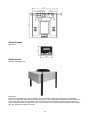
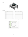
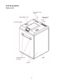
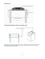
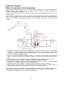
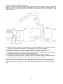
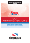
OWNER’S MANUAL
SPLIT
AIR TO WATER HEAT PUMPS
SHP-140IRC+SHP-140ERC
SHP-180IRC+SHP-180ERC
H E AT P U M P S
Contents
Basic information ..........................................................................................................................................2
Cautions and Warnings .................................................................................................................................3
Safety precautions ........................................................................................................................................7
Transportation ..............................................................................................................................................8
Inspection and storage ..................................................................................................................................8
Product description .......................................................................................................................................9
House heating and hot water supply ........................................................................................................... 10
Heat pump functions ................................................................................................................................... 10
Specifications ............................................................................................................................................. 11
Packing....................................................................................................................................................... 12
Dimensions and heat pump appearance ..................................................................................................... 13
Indoor unit............................................................................................................................................... 13
Control panel .......................................................................................................................................... 15
Outdoor unit ............................................................................................................................................ 15
Unit description ........................................................................................................................................... 17
Indoor unit............................................................................................................................................... 17
Outdoor unit ............................................................................................................................................ 18
Connections between indoor and outdoor unit ......................................................................................... 18
Operation range .......................................................................................................................................... 19
Capacity specifications................................................................................................................................ 19
Place of installation ..................................................................................................................................... 20
Method of installation .................................................................................................................................. 22
Water connections ...................................................................................................................................... 23
Hydraulic diagram ....................................................................................................................................... 24
Basic components of the heat pump ........................................................................................................... 24
Water pump ............................................................................................................................................ 26
Electrical connections ................................................................................................................................. 27
Trial operation............................................................................................................................................. 27
Maintenance and cleaning .......................................................................................................................... 28
Indoor unit............................................................................................................................................... 28
Outdoor unit ............................................................................................................................................ 28
Check of filling pressure of the heating system ............................................................................................ 29
Common faults and troubleshooting ............................................................................................................ 30
Error messages and solutions ..................................................................................................................... 31
Options ....................................................................................................................................................... 31
Recycling .................................................................................................................................................... 31
Warranty conditions .................................................................................................................................... 31
Service ....................................................................................................................................................... 32
SAFETY DATA SHEET............................................................................................................................... 33
Manufacturer: ............................................................................................................................................. 40
1
Basic information
Welcome in the world of air-source water heat pump. Your decision to purchase heat pump will reward you
for many years. This is your assurance that you have purchased quality heat pump system, which is
manufactured based on the latest level of knowledge and innovation.
We are pleased to introduce new powerful high temperature heat pump S-THERM+ series, which has been
tested based on EHPA and EN 14511 standards and reached excellent results in energy-efficiency; these
results are indicated in submitted protocols.
Control units of existing air-water heat pumps adjust refrigerant quantity through thermostatic or electric
expansion valve to set temperature based on temperature and pressure of refrigerant without taking into
consideration status of additional nodes of heat pump system.
Control unit of SINCLAIR S-THERM+ heat pump optimizes the control process of heat pump
comprehensively, which means that control unit uses several additional data sources, gathered in important
nodes of the whole system. Control process is thus expanded with the data of outdoor temperature,
compressor temperature, refrigerant temperature and pressure, position of control valves, heating water
temperature and flow, air flow through evaporator etc.
This comprehensive way of heat pump controlling can react more quickly and precisely to the changes of
physical quantities, which have influence on the efficiency of the whole system. Next advantage brings the
fact, that monitoring these important physical quantities gives the control unit the possibility to foresee
expected changes and react in advance. As a result of this, control process becomes smoother without
fluctuations and overshooting, which is typical for existing less sophisticated or versatile control units.
Operation of SINCLAIR S-THERM+ heat pump system is thus much more stable.
High temperature heat pump SINCLAIR S-THERM+ and its control unit was designed as a complex system
providing efficient management of thermal energy to guarantee balanced and efficient operation of a house,
inclusive integration of solar cells as a additional source of thermal energy and a possibility for swimming
pool heating. But the system is of course for its operation dependent on continuous supply of necessary
amount of electric energy from distribution network. For the case of power supply failure, there is the
possibility to add a special optional battery operated GSM module, which can in the case of power failure
send SMS message to given telephone numbers informing about this event; in case of fatal failure of the
system, message defining current status can be sent to the user, giving him a chance to take necessary
steps for system operation recovery or to take necessary measures.
Standard equipment includes also LAN module, which gives the possibility of remote control and monitoring
via internet network.
Read before use
The following instructions will guide you through the whole documentation. Besides this operation manual
there are also other manuals to be respected. Please read this operation manual and installation instructions
carefully and keep these manuals on a safe place. Should there will be a change of user of this product,
please pass this manual to a new user. Make this manual available for service engineers when providing
service and maintenance work.
When operating the unit, please follow strictly all instructions also for other components of your heating
system. Let an authorized service company to make detailed training in operation of heat pump system.
During operation please make only activities, described in this operation manual.
Manufacturer takes no responsibility for any damage, caused by not following operation instructions.
Qualified persons
Product positioning, its installation and commissioning can be done only by trained person, working in
accordance with all instructions in operation and installation manual.
2
Safety
Where children or persons with limited physical, sensory or mental capabilities are to be allowed to operate
this equipment, ensure that this will only happen under supervision or after appropriate training by a person
responsible for their safety. Children should be supervised to ensure that they do not play with the
equipment.
For your information
Pictures and drawings in this manual are for your information only. The manufacturer reserves the right to
make a change or improvement to the product when necessary, without prior notification of the users of this
device.
Quality check upon receiving product
Upon the unit delivery, please check if there is any damage due to transport. If any damage is found on the
unit, please inform the transport company or the manufacturer in written form immediately.
If the heat pump should be installed later, please protect it against damage, rust or abrasion taking the
following measures:
1. All input locations like water connections must be sealed correctly.
2. Unit must be protected from sunshine and placed in locations with a temperature below 450C.
3. Unit must be protected from dust to avoid dirt coming to the evaporator.
4. Unit must be stored in a place, where it creates no obstacle and can cause no accident.
5. Please check the unit regularly when stored.
This product is equipped with European Union compliance sign CE.
This product was tested by state accredited laboratory.
Cautions and Warnings
In order to protect users and other people from possible harm caused by this unit and in order to avoid
damage to the unit or other property and to guarantee proper use the heat pump, please read this manual
carefully and follow given instructions.
The piping connection and wiring should be installed according to the local laws and regulations as well as
the profession standard. Mainly work on electrical parts and on refrigerant circuit requires professional
qualification. Heat pump system (indoor and outdoor unit) can be operated (with the exception of
maintenance) only with closed casings. In other case there can come under unfavorable operation conditions
to damage on equipment or even to personal injury or death.
Remarks to symbols
Symbol
Meaning
Incorrect handling could result in personal injury or death.
WARNING
CAUTION
Incorrect handling may result in minor injury, or damage to product
or property.
3
Remarks to icons
Icon
Meaning
Subject of prohibition is indicated next to the icon.
Prohibition!
Indicated action must be done.
Mandatory action!
Follow given instructions.
Warning!
Warning
Icon
Meaning
Mandatory action!
If you find there is a fault or abnormal behavior of the unit, stop operation
and switch off by disconnecting power cable from the socket, or by
switching off main switch or circuit breaker.
(Risk of smoke/fire/electrical shock).
Installation
Meaning
Must be done by qualified
person.
Good earth connection
necessary.
In order to avoid mistakes like wrong sealing of water connections, risk of
electrical shock or fire, installation of heat pump must be done by qualified
person.
Please check good earth connection of the unit and power supply,
otherwise there is a risk of electrical shock.
Operation
Meaning
DO NOT INSERT your finger and other objects into fans and evaporator,
otherwise there is a risk of injury.
PROHIBITION
Switch off power supply
If the unit does not run properly or you can feel a strange smell, it is
necessary to switch the unit off immediately and stop the operation.
Otherwise there is a risk of electrical shock or fire.
If water or foreign objects entered the unit, switch off power supply
immediately.
Switch off power supply
If circuit breaker tips frequently, disconnect the unit from power supply.
Switch off power supply
4
Do not insert your fingers or other objects into indoor or outdoor unit,
rotating parts could cause an injury.
PROHIBITION
Do not put any objects on the unit or directly under it.
PROHIBITION
Transport and repairs
Meaning
Ask for help
If it is necessary to move the unit or to make a new installation, please ask
for help your supplier or a qualified person. Wrong installation can cause
water leakage or risk of electrical shock or fire.
Ask for help
If it is necessary to repair the unit, please ask for help your supplier or
a qualified person. Wrong repair can cause water leakage or risk of
electrical shock or fire.
It is prohibited to make repairs by yourself, as this can cause risk of
electrical shock or fire.
Prohibited
It is recommended to wear protective gloves when providing maintenance
or repairs.
Warning!
Caution
Installation
Meaning
Unit MUST NOT be installed near combustible gases. If there is a gas
leakage, there is a risk of fire.
Place of installation
Make sure the installation place for the unit is strong enough, in order to
prevent tilt or fall of the unit.
Security of the unit
Make sure the power supply line is equipped with a circuit breaker,
otherwise there is a risk of electrical shock or fire.
Circuit breaker of power supply
Power supply cable
Do not use for power supply cables which are modified or combined, do
not use extension cords or cables with unknown origin or parameters,
otherwise these could be overheated and cause a fire.
5
If power cable is damaged, it must be replaced by a qualified person in
order to avoid a risk of electrical shock.
Power supply cable
Unit must have a good earth connection, otherwise there is a risk of
electrical shock or fire.
Earth connection
Operation
Meaning
Place of installation
Please make a regular check (once per month) of the installation place, in
order to see, if there is no tilt or damage to the base, which could lead to
person injury or unit damage.
Switch off power supply when cleaning or providing maintenance of the
unit.
Switch off power supply
It is strongly prohibited to replace a fuse by a piece of wire. Correct value of
fuse must be determined by a qualified specialist.
PROHIBITION
Do not operate the unit with wet hands, in order to prevent the risk of
electrical shock.
Warning!
6
Safety precautions
1) Prevention of explosion and fire
Some parts of heat pump (indoor unit) can become very hot.
Do not touch any pipes of heating system which have no thermal insulation.
Do not remove any parts of casing.
2) Prevention of frostbites
Supplied heat pump (indoor unit) is charged with refrigerant R407c. This refrigerant contains no chlorine and
thus represents no damage for ozone layer of the Earth. Refrigerant R407c is not inflammable and forms no
risk of explosion. But leaking refrigerant can cause frostbites on affected areas.
In case of refrigerant leak do not touch any part of heat pump.
Do not inhale fumes or gases, which come out from leaks.
Prevent contact refrigerant with skin or intrusion into your eyes.
When there is a refrigerant contact with a skin or intrusion into eyes, search for medical assistance.
3) Prevention of injuries
The air coming out from the outdoor unit is colder than outdoor temperature. By temperatures below 5 °C
can come to ice forming in this area. This ice represents a certain danger of slipping.
Do not forget possible ice forming under the outdoor unit. Take necessary measures to prevent possible
danger to persons near the outdoor unit.
4) Prevention of injuries due to unqualified modifications
Do not damage or remove seals and safety locks on individual parts of the unit. Modifications of sealed and
locked parts can be done only by authorized service engineers and customer service.
Prohibition to make any changes is valid for:
– heat pump system,
– surroundings of heat pump system,
– water and electricity supply.
Please make under no circumstances any modifications or changes in the heat pump system or in other
parts of heating system and hot water preparation.
Please do not make any additional site structural changes, which could restrict available space for the unit or
other steps, which could lead to a temperature changes on indoor unit installation place.
5) Prevent possible damages to the house caused by condensate water
Piping system between indoor and outdoor is cold which means the condensate can form on piping inside
the house. This could lead to a material damage, e.g. as a result of corrosion.
Please make sure the piping insulation is not damaged.
When there is a insulation damage, please call service engineer immediately.
6) Prevent environment damage
Heat pump (indoor unit) contains refrigerant R407c. This refrigerant must never escape into the atmosphere.
Refrigerant R407C is a fluorinated greenhouse gas with GWP 1653 (GWP = Global Warming Potential)
covered by the Kyoto Protocol. If this refrigerant escapes into the atmosphere, its effect is 1653 times
stronger than the natural greenhouse gas CO2.
Before disposal of the heat pump, refrigerant in the system must be completely sucked up into a suitable
container in order to have later the possibility to recycle or to dispose the refrigerant according to the valid
rules and regulations.
Please ensure all maintenance work connected with access to the refrigerant circuit is made only by officially
certified qualified persons and using corresponding protection tools and equipment.
Please let the refrigerant in the heat pump system to be recycled or disposed by a qualified person in
accordance with valid rules and regulations.
Please consult all matters related to the installation, repairs, dismantling or moving the unit with the
authorized supplier. Wrong made installation can lead to water or refrigerant leak, risk of electrical shock or
fire.
7
Transportation
Please transport the unit always in the upright position. Do not lay it on its side, otherwise some internal
parts could be damaged. During transportation and loading down avoid any sudden movements. When
moving, touch the unit always on its base part. When using a fork lift, use always a protective block between
the forks so that there is no damage to the unit and its covers. This protective block must be along the entire
width of the unit.
If it is necessary to lift the unit during the installation, it is
necessary to use a rope 8 m long and to insert some soft
protective material between rope and the unit to prevent
damage of covers. See the picture to the right. Fork lift can be
use to lift the unit too, as the package has a strong wooden base.
PROHIBITION
DO NOT TOUCH heat exchanger with your fingers and other
objects!
Inspection and storage
Upon delivery it is necessary to see the packing list and check all items, if the delivery is complete.
It is also necessary to check, if there is no damage on any delivered part.
When there is any damage, please inform transportation company immediately. After unit acceptance the
manufacturer takes no responsibilities for any damage during transportation.
WARNING!
Sharp edges and exchanger surface can cause injury. Please do not touch these parts.
8
Product description
The air-source heat pump extracts heat from outdoor air and transfers it into water. Heat pump systems
consist of separated circuits, where heat is transferred from its source to the heating system using liquids or
gases. As these circuits use different media (air, refrigerant and heating water), circuits are connected
through heat exchangers. These heat exchangers provide transfer of thermal energy.
Heat pump is used to heat buildings using accumulating hot water into heat water tank (using the tank is not
a condition for heat pump operation), where water tank must have a volume appropriate to the building size.
Size of accumulated water tank must be determined by a designer, based on the thermal loss of the building.
Effective heating of the building is reached by circulation of this heated water. When using under floor
heating, the heat pump can reach COP value up to 4,5. Normal water temperature for under floor heating is
35 °C, temperature 40 °C to 50 °C is used for heating with fan coils (heat exchangers with fan), temperature
35 °C to 65 °C is used for radiators, or other temperature can be used based on the request of the user.
If necessary, the unit can also work in reverse mode and heat pump can be used for cooling. When used for
cooling, water is cooled down to the temperature of 12 °C.
Compared with oil boiler, gas boiler and electric heater represents the heat pump the best solution thanks to
its efficiency, safety and environment protection.
This high temperature air-water heat pump uses advanced technologies for heating and intelligent control
system to produce water warmer than 65 °C. Heat pump can therefore supply hot water for under floor
heating, heat exchanger (fan coil) or radiator and thus replace water boiler directly.
Heat pump can be furthermore used for production of high temperature water for sanitary purposes, as for
example for use in kitchen, for showers and so on.
Any other purpose of using can be considered as utilization, which is not in compliance with its
determination. Manufacturer/supplier takes therefore no responsibility for any damage thus incurred. The risk
is on the side of user.
System consists of two units (indoor and outdoor), which are connected with a copper refrigerant piping.
Other components and parts of the heating system are delivered and installed by installation company or
other subcontractor and it is necessary to use components, according to the purpose and utilization of the
system.
Connection between heat pump and accumulation tank should be as short as possible, as simple as
possible any with minimal bends. In case it is necessary to make a bend, it is recommended to make an
elbow rather than a bend. Size of the connection between heat pump and accumulation tank should be at
least DN25, so that sufficient flow of 2,0-2,8 m3/h can be guaranteed.
Heat pump is equipped with one auxiliary electric heater, which can be used:
To support heating and hot water supply when there is an insufficient heat supply from heat source.
For an emergency mode, when there are faults with permanent heat pump switch off.
To keep emergency protection against frost during these faults.
Auxiliary electric heater can be used for heating and/or hot water supply.
Building (and indoor units)
Water tank &
Expansion tank
Air-water heat pump
Heat pump can be used for two circuits (example)
Illustrations have only informative character, the final solution will be prepared by a designer or the
installation company.
9
Heat pump is equipped with an intelligent control system with the possibility of controlling up to 18 switch
relays with the capacity of 230V/2A max. Besides this, the system can control two step motors of expansion
valves and the control board has two outputs with voltage 0 to 10V for exchanger fan speed control or heat
pump compressor control. Heat pump can be controlled from supervising system via communication cable or
can be controlled remotely via Internet or mobile phone; for more details and possibilities please
see Operation manual.
IMPORTANT REMARKS:
Illustration above shows only the main parts and the main purpose of utilization; several additional
components must be installed by qualified person in order to guarantee safety and maintenance possibilities,
as for example water connections, venting valves, flexible piping, control valves, pressure gauges, water
filters, water temperature gauges, drainages and similar.
House heating and hot water supply
As the heat pump can supply hot water with the
temperature even over 65 °C, it can provide also
water for sanitary purposes when second tank for
hot water is provided.
REMARKS: To accomplish the whole system, it is
necessary to use additional components and
control.
Heat pump functions
Copper connection pipes
1. Protection of our planet with the help of green technology.
2. Heat pump transfers the heat from the air into the heated area without any combustion, no waste is
created, no harmful gases are emitted - clean environment is preserved and less waste is created.
3. Help for the population thanks to high efficiency and money saving.
4. Heat pump is driven by electric energy and its average coefficient of performance (COP) can be higher
5.
6.
7.
8.
than 4,0. With the help of timer function users can use electric energy during periods of lowest cost and
so save money for the whole family.
Save operation.
Utilization of heat pump for heating can prevent possible risk of electric shock or burning and people are
protected against explosion or poisoning.
Easy operation.
Heat pump is controlled and protected by control board, requested water temperature is set based on real
requirements. Protecting system can ensure operation even under heavy conditions.
Heating mode
Cooling mode
Evaporator defrost
Control temperature correction (time constant, temperatures, equithermal control)
Programming (timer setting)
Priorities
Rate utilization
Emergency mode
Heat pump system switching off
If it is necessary to switch off the system of heat pump, it must be completely disconnected from power
supply.
10
Specifications
This operation manual is valid exclusively for the following models of heat pump:
Model
Outdoor unit
SHP-140ERC
SHP-180ERC
Indoor unit
SHP-140IRC
SHP-180IRC
kW/kW/A/-
14,70/3,28/11,0/4,49
16,79/3,94/11,0/4,26
Heating
°C
-20~40
-20~40
Cooling
°C
18~40
18~40
DHW (domestic hot water)
°C
-20~40
-20~40
°C
12~65
12~65
-
A
A
V/Ph/Hz
380/3/50
380/3/50
A
59
59
Capacity / Power input / Current / COP
Range of
operation
temperatures
Range of output water temperature
Energy class
Indoor unit power supply
Starting current
Electric heater
Number
pcs
1
1
Power input
kW
3,0
3,0
Operation current
A
4,6
4,6
Model
-
ZH13KVE-TFD
ZW61KSE-TFP-542
Brand
-
Copeland EVI
Copeland EVI
SCROLL
SCROLL
Type
Compressor
Number
pcs
1
1
Power input
W
3480
4900
Rated current (RLA)
A
8,7
9,8
Starting current (LRA)
A
59
STRATOS PARA 25/18
140
Power input
W
64
STRATOS PARA 25/18
140
Min/max discharge
m
1/8
1/8
Type
-
R407c
R407c
kg
8,0
8,0
type
M3G084-GF
M3G084-GF
W
182,0
182,0
r/min
655,0
655,0
Pa
45,0
45,0
3
4995,0
4995,0
Model
Water pump
Refrigerant
Refrigerant charge
Motor
Power input
Fan
Speed
Max. pressure
Air flow
m /h
11
Model
Outdoor unit
SHP-140ERC
SHP-180ERC
Indoor unit
SHP-140IRC
SHP-180IRC
Outdoor unit dimensions (w/d/h)
mm
1168*1063*1102
1168*1063*1102
Indoor unit dimensions (w/h/d)
mm
602*638*1035
602*638*1035
Outdoor unit weight
kg
94
94
Indoor unit weight
kg
159
150
Max. noise level outdoor unit in 1 m
dB(A)
58
58
Max. noise level indoor unit in 1 m
dB(A)
51
51
Max. temperature of heating water
°C
65°C
65°C
Electrical protection
A
16,0
16,0
mm
12/22
12/22
Pipe max. length
m
8
8
Pipe max. height difference
m
3
3
Mpa
4,2/2,6
4,2/2,6
Diameter
Height difference
(accumulation tank/indoor unit)
mm
DN25 (1")
DN25 (1")
m
1
1
Optimal flow
m3/h
2,8
2,8
Minimum flow
m3/h
2,0
2,0
Pressure drop
kPa
19,9
19,9
Liquid / Gas
Refrigerant
pipe
Operation pressure
Water pipe
Additional refrigerant charge: 115 g per 1 m pipe.
Above given values are only informative. Actual specifications can be found on nameplate of the unit.
Heat pump system can be operated under all rates of electric energy consumption.
Packing
Dimensions
Indoor unit SHP140IRC
Indoor unit SHP180IRC
Venkovní
jednotka
Balení
1 wooden casing on
palette
Obsah
Rozm ry (mm)
Whole unit
w 710 x d 710 x h 1220
Weight brutto
(kg)
175
165
1 cardboard on palette
Evaporator
1 cardboard
Fan
12
w 1220 x d 1040 x h 760
86
w 815 x d 815 x h 260
17
Dimensions and heat pump appearance
Indoor unit
Indoor unit appearance
Description
Indoor unit provides efficient heat exchange between the refrigerant circuit and the water circuit and is
located inside a house or a building. Indoor unit stands on a steel base with four rubber feet. Heat pump
components are located inside the indoor unit. Side parts of the unit are made of painted plates. Side and
rear covers are fixed with screws, front cover is removable with the help of two small handles. Upper cover
panel is made of plastic. Control panel with display and rotary selector (JOG) is located on the front part of
the upper cover. Piping and electrical connections are guided from upper side and are not covered.
Components of refrigerant circuit are inside the heat pump (indoor unit) covered with insulation, so that no
condensate can be formed on these parts. If anyway some small quantity of condensate water is formed, it is
collected into a water tray. Water tray is located inside the heat pump, in its lower part. Heat created inside
the heat pump causes evaporation of this condensate water in the tray. Small quantity of condensate can be
drained out under the heat pump. Creation of a small quantity of condensate water means no malfunction of
the heat pump.
13
Views
Dimensions
14
Control panel
Dimensions
Outdoor unit
Outdoor unit appearance
Description
Outdoor unit (evaporator) is located outside a house or building. Main part of the unit is the evaporator,
which is covered from upper side, from back side and from cover sides with metal plates, which are fixed by
rivets and therefore are not removable. Front metal cover is fixed with screws and covers electric box for
communication and power cables connection. Fan is located in the upper part and is protected with a black
grill. The evaporator stands on four feet.
15
Views
Dimensions
Console dimensions
16
Unit description
Indoor unit
Secondary circuit
- water
In
Out
Upper plastic cover
Primary circuit
- refrigerant
Liquid
Gas
Panel with display
Base
Handles for cover
removing
Covers
17
Outdoor unit
Fan with motor protected by grill
Electric box
Evaporator with casing
Feet
Connections between indoor and outdoor unit
Copper pipes
Copper pipes are used to connect indoor and outdoor unit. Piping must be installed by specialized company
and piping must be as short as possible and with minimum bends. Specialized company will install also
communication and power supply cables.
18
Water temperature (°C)
Operation range
Outdoor temperature (°C)
Capacity specifications
CAPACITY SPECIFICATIONS
Ambient temperature (A) / Output water temperature (W) (°C) *
SHP-140
SHP-180
Model
Heating capacity (kW)
18,28
22,32
A20/W35
Power input (kW)
3,28
3,83
COP (-)
5,58
5,82
Heating Capacity (kW)
15,55
17,88
A10/W35
Power Input (kW)
3,28
3,90
COP (-)
4,75
4,58
Heating Capacity (kW)
14,73
16,79
A7/W35
Power Input (kW)
3,28
3,94
COP (-)
4,49
4,26
Heating Capacity (kW)
11,38
13,27
A2/W35
Power Input (kW)
3,06
3,77
COP (-)
3,72
3,52
Heating Capacity (kW)
10,30
11,09
A-7/W35
Power Input (kW)
3,17
3,85
COP (-)
3,25
2,88
Heating Capacity (kW)
8,81
10,43
A-15/W45
Power Input (kW)
4,09
4,95
COP (-)
2,16
2,11
Cooling Capacity (kW)
10,90
12,50
Power Input (kW)
3,41
4,46
A35/W12
EER (-)
3,20
2,80
* Values measured according to the Standard EN 14511-2:2012 / EHPA.
Measurement contains also defrosting cycle.
19
Place of installation
Outdoor unit
Outdoor unit can be installed on any place outside, which can carry the weight of this heavy unit as
e.g. terraces, terrain etc.
Place of installation must be protected against influences of heat or fire.
It is recommended to use protective covers or roofs to protect the unit against snow in winter.
Areas of heat pump air input and output must not be blocked by any obstacles.
Drainage channel must be built around the unit to drain condensate water. See Method of
installation.
Place of installation must be protected against strong air blowing.
There must be space enough left around the unit for maintenance and service work.
Danger of injury due to ice formation!
WARNING
The air coming out from the outdoor unit is colder than outdoor temperature. Therefore ice can be formed by
temperatures below 5 °C. This ice represents a danger of slipping.
Danger of damage or malfunction due to a blown snow!
WARNING
Areas of air input and output must remain free of obstacles in order to guarantee sufficient and not hindered
air blow.
Outdoor unit must be installed in a distance at least 3 m from public roads.
• Please ensure locally common and by law determined minimum distances are kept to the following
objects: vegetation, canvas, walls, open fire and heat radiation, places where children can play.
• Please keep air input and output of outdoor unit free of frost.
• Operation of outdoor unit emits a certain level of noise, which can become stronger on hard
surfaces; therefore place of installation must be chosen very carefully. (These value are dependent
on heat pump performance).
20
Indoor unit
Place of installation must have a good ventilation.
Indoor unit must be installed inside a house or building (cellar, veranda, service or technical room
etc.) on a dry place, where unit will be permanently protected against frost and where temperature
range of 7°C to 25° is kept, or on any other place which is clean, bright and has a good ventilation.
Place of installation should have a minimum volume (Vmin) according to the standard EN 378;
T1.Vmin=G/c, where G is a refrigerant charge in kg and c is an applicable limit value in kg/m3 (for
refrigerant R407c the value of c is 0,31kg/m3). Minimum volume for the unit SHP-180IRC is 25,8m 3.
It is prohibited to make any additional construction work, which could lead to the volume reduction or
any other modification, which could cause a change of temperature on indoor unit installation place.
If the unit is installed on a free accessible place, it is necessary to protect the unit by a suitable
securing covers.
As an installation place is recommended to select a place, where unit will not disturb surroundings by
its operation noise or by hot air.
The unit should be installed close to electric power supply.
Covers of the unit are made of painted steel, please protect these parts against humidity.
Upper side of the unit is made of plastics, please protect this part against heavy objects.
Please leave a sufficient space around the unit for maintenance and service work.
21
Method of installation
Heat pump can be installed on the floor on a concrete base using spacer screws or on a metal frame using
rubber feet. Please ensure the unit is installed horizontally.
1) Prepare a foundation for outdoor unit installation.
2) Build concrete pillars, where feet of the outdoor unit will stand. Respect all principles for construction
work and security.
3) Lay a drainage hose for condensate drainage and cover with gravel to the height of about 200 mm.
4) Lay copper piping and communication cables in a protective tube into the requested place and
positioning.
5) Put additional gravel up to the top of the hole and align with terrain.
6) Fix feet of outdoor unit to the foundation using suitable screws.
Gravel ground
- height min. 600 mm
Protective tube for piping and cables
Drainage
hose
22
Water connections
When making water connections, take into consideration remarks below:
Heat pump is determined to be connected to a closed system of central heating. In order to
guarantee fault-free operation, central heating installation must be made by authorized specialized
persons and in accordance with corresponding standards and rules.
Try to reduce water resistance in the piping.
Piping must be clean and without any dirt and obstructions. It is necessary to make a leak test and
check that there is no water leaking.
Piping pressure test must be done separately. DO NOT MAKE the test, when the heat pump is
connected.
There is a flow switch mounted inside the heat pump. Ensure correct connection of this switch and
its function and its control by control unit.
It is better to make the connection between the heat pump and the building as a flexible connection,
so that transfer of vibrations is eliminated. Water piping holders must be made independently and
must not use the unit of heat pump.
Try to prevent air presence in a water piping and mount venting valve to the upper part of water
distribution system.
For easy inspection during the operation, it is necessary to install temperature and pressure gauge
to the water input and output.
Lower parts of water distribution system must be equipped with a drain outlet and a drain outlet is
already mounted on the heat pump frame. If heat pump is not running, then it is necessary to drain
the water from the system in winter time. For water distribution system venting, a venting valve must
be mounted on the upper side of the system. For easy maintenance, it is not necessary to make an
insulation on the drain part and venting valve. Drain parts and venting valve are not parts delivered
with the heat pump; these parts must be supplied by an installation company.
Danger of equipment and system damage due to the use of water with high
content of calcium and magnesium!
Caution!
23
Hydraulic diagram
Basic components of the heat pump
Install hydraulic components according to the local requirements analogically to the following examples of
hydraulic diagram. (This example of hydraulic diagram does not contain all closing and safety parts,
necessary for professional installation.)
Version 1: Heat Pump with a Combined stainless flow water heater for DHW located in buffer tank for water
for heating circuit.
This is the most complex solution - system consists of combined multipurpose free flow accumulation tank,
which serves for heating of domestic hot water (DHW) and accumulation of hot water for heating and heating
system, which consists of radiators and underfloor heating. Optional part can be heating using solar
collector.
a) Simple buffer tank for heat pump for heating water circuit with the volume of 400, 500, 600L in PU foam
insulation - very compact (we will deliver). The possibility to connect a solar exchanger. This buffer tank
contains also stainless exchanger for DHW heating. Upper 1/3 of the tank provides DHW heating. Lower
part of the tank provides DHW preheating.
b) 2 pcs of 3-way valve for switching between the upper 1/3 of the tank for DHW heating and between the
lower 2/3 of the tank for heating circuit: ESBE series VRG 131/132 DN size of connection will be specified
later.
c) Electronic control of 3-way valves for tank switching: ESBE series 641 (operation time 30 seconds).
d) Pump Grundfos for water circulation in radiators (if heating with radiators is installed).
e) 3-way valve for equitherm regulation of water temperature in radiators (if radiators are installed): ESBE
series VRG 131/132 DN size of connection will be specified later.
f) Pump Grundfos for water circulation in underfloor heating (if underfloor heating is installed).
g) 3-way valve for equitherm regulation of water temperature in underfloor heating (if underfloor heating is
installed). ESBE series VRG 131/132 DN size of connection will be specified later.
3-way valves for equitherm regulation of water temperature in radiators and in underfloor heating will be
controlled exclusively by electronic control of the type: ESBE series 671 (operation time 240 seconds).
ATTENTION: this configuration cannot be used for cooling mode.
24
Version 2: Heat Pump + Sinclair water heater
System consists of accumulation tank for heating system (radiators and underfloor heating); optional solar
heating can be also connected. Domestic hot water (DHW) can be then heated by a separate heater (e.g.
SWH-15/190T or SWH-35/300TL) without solar heating or SWH-35/300TSL with the possibility of solar
heating connection.
a) Simple buffer tank for heat pump for heating water circuit with the volume of 400, 500, 600L in PU foam
insulation - very compact (we will deliver). The possibility to connect a solar exchanger.
b) Small Sinclair heat pump for independent DHW heating either with solar heating or without this.
c) Pump Grundfos for water circulation in radiators (if heating with radiators is installed).
d) 3-way valve for equitherm regulation of water temperature in radiators (if radiators are installed): ESBE
series VRG 131/132 DN size of connection will be specified later.
e) Pump Grundfos for water circulation in underfloor heating (if underfloor heating is installed).
f) 3-way valve for equitherm regulation of water temperature in underfloor heating (if underfloor heating is
installed). ESBE series VRG 131/132 DN size of connection will be specified later.
3-way valves for equitherm regulation of water temperature in radiators and in underfloor heating will be
controlled exclusively by electronic control of the type: ESBE series 671 (operation time 240 seconds).
This configuration can be used also for cooling mode. Different types of fan coils can be used as cooling
units.
25
Version 3: Heat Pump with two Separate tanks
System consists of accumulation tank for heating system without the possibility of connecting to a solar
heating connected with DHW tank with or without the possibility of connecting to a solar water heating.
a) Simple buffer tank for heat pump for heating water circuit with the volume of 400, 500, 600L in PU foam
insulation - very compact (we will deliver). The possibility to connect a solar exchanger.
b) Separate DHW tank (supplier not known at this moment). Tank will have a capacity of 200 and 300 liters
with the possibility of solar exchanger.
c) 2 pcs of 3-way valve for switching between DHW tank and tank for heating circuit. ESBE series VRG
131/132 DN size of connection will be specified later.
d) Electronic control of 3-way valves for tank switching. ESBE series 641 (operation time 30 seconds).
e) Pump Grundfos for water circulation in radiators (if heating with radiators is installed).
f) 3-way valve for equitherm regulation of water temperature in radiators (if radiators are installed): ESBE
series VRG 131/132 DN size of connection will be specified later.
g) Pump Grundfos for water circulation in underfloor heating (if underfloor heating is installed).
h) 3-way valve for equitherm regulation of water temperature in underfloor heating (if underfloor heating is
installed). ESBE series VRG 131/132 DN size of connection will be specified later.
3-way valves for equitherm regulation of water temperature in radiators and in underfloor heating will be
controlled exclusively by electronic control of the type: ESBE series 671 (operation time 240 seconds).
This configuration can be used also for cooling mode. Different types of fan coils can be used as cooling
units.
Water pump
Circulation pump, seal less type, electronic
Type: STRATOS Para 25/1-8
Maximum discharge: 8 m
Max. flow: 8 m3/h
Max. operation pressure: 6 bar
Nominal capacity: 100 W
Speed: 1400-3700 rev./min.
Consumption: 8-140 W
Current by 1~230 V: 0,09-1,30 A
26
Electrical connections
Before starting the work on electrical connections ensure, the power supply corresponds to the data on
manufacturer´s nameplate and check also the electric characteristics of the unit.
Important: person making the installation is responsible for connection of unit protective circuit breaker,
which must have parameters corresponding to the capacity of the unit (see table with electric characteristics
of the unit).
Connection to the electric distribution network must be done in compliance with valid standards and
regulations.
Procedure for electrical connection: remove the inspection panel, which will allow access to the electrical
box. For removing of inspection panel take out the control unit from its holder. Pull the power supply cable
through the cable bushing.
WARNING!
Connections must be done according to the wiring diagram, which is located on the electric box.
Wires of power supply cable must be made of copper and must have the cross-section in compliance with
valid standards.
Earth connection of the unit must be done through earthing clamp, located inside the electric box.
Power supply voltage must not have fluctuations of more than 10%. Phase unbalance must not be more
than 3%.
All wires are connected through screw terminals.
Wire insulation must removed in the length of 10 mm.
Trial operation
Check before trial operation:
Check the indoor unit and ensure all pipes are in order and respective valves are open.
Check electrical connections. Check the power supply, fixing of screw connections, correct
connecting according to the wiring diagram and correct earthing of the unit.
Check the heat pump inclusive all screws and parts of the pump to see they are ok. After switching
on check control unit indicators to see there is no malfunction. During the trial operation it is possible
to connect a pressure gauge to the test valve and check high pressure (or low pressure) of the gas.
Trial operation:
After the first power connection heat pump will activate (LCD display will illuminate), necessary test
will be done automatically and heat pump is waiting for next settings in stand-by mode.
Check if the water pump is running and if it is running normally.
After 1 minute of operation of water pump, compressor will start. Listen, if there is no strange sounds
coming out from the compressor (noisy knocking, squeaks…). If this should be the case, switch the
unit off and check the compressor.
Set valves of water distribution so, that warm (cold) water distribution to each branch is correct and
corresponds requirements for heating (cooling).
Check whether the temperature of output water is stable.
27
Maintenance and cleaning
Indoor unit
Before starting the maintenance and cleaning of the heat pump switch
always power supply off!
WARNING
When cleaning the heat pump, do not use thinner, benzene or other aggressive cleaning solutions or
powder, do not use water warmer than 40°C.
Cleaning can be done with a neutral soap or any non-aggressive common cleaner for the use in the
kitchen. If you are not sure about steps to be done, ask service engineer to make the preventive
maintenance.
Do not pour water on the control panel of the indoor unit, clean only with a dry and soft cloth.
Check regularly water supply and venting so, that there is no shortage of water in the system. In
some intervals check also the water filter, so that water of good quality is guaranteed. Shortage of
water or dirt in the water can damage the unit.
Operate the unit on a dry and clean place with a good ventilation. In order to guarantee a good heat
exchanging and energy saving, clean the heat exchanger once in 1 to 2 months.
Check individual parts of the unit and the pressure in the system. If some parts are defective, replace
these and add the refrigerant as needed.
Check electric supply and electric system, check if individual electrical parts have no defects, if wire
connections are correct. If any part does not work correctly or emits some smell, replace this part in
time.
If the heat pump will not be user for longer time, drain all the water from the system and block all the
holes. In order to prevent freezing in winter, drain the water on the lowest part of the heat exchanger.
Before re-starting the unit it is necessary to fill the water again and make an overall check.
Heat pump water distribution MUST BE protected against freezing in winter.
If you are not sure about procedures to be done, ask service engineer to
make the preventive maintenance!
WARNING
Outdoor unit
Removing the frost from the evaporator must not be done with a sharp object, otherwise the
evaporator could be damaged. Frost can be removed using a flow of hot air with a maximum
temperature of 50°C or with a mild flow of warm water with a maximum temperature of 50°C.
Cleaning of the outdoor unit can be done only with all casing mounted.
Outdoor unit is protected against splashing water and can be therefore cleaned with a soft stream of
water.
Danger of damage due to the unqualified cleaning!
WARNING
High pressure cleaning equipment can damage plates of heat exchanger behind plates grill.
•
Casing cleaning can be done with a soft sponge and warm water (max. 50 °C) and commercially
available cleaning agents for household (without sharp particles) in form of water solutions up to the
concentration of max. 2 %. Do not use any sanitary cleaning agents containing chlorine or ammonia!
Permanent safe and reliable operation and a long service life can be reached under assumption, that heat
system is inspected/maintained at least once a year by a qualified specialist.
28
Danger of injury and damage due to the unauthorized maintenance
and repair!
WARNING
Never try to make repair or maintenance of the heat pump by yourself.
PROHIBITION
Service engineer should be authorized for this activity.
In order to guarantee all functions of S-THERM+ unit permanently and to keep correct and approved working
order, only original S-THERM+ spare parts can be used exclusively for maintenance and service work!
Check of filling pressure of the heating system
Filling pressure of your heating system can be read on the pressure gauge, which was installed as a part of
heating system by a specialized company during the installation. This pressure should be between 1 and 2
bar. When the water pressure drops below 0,5 bar, indoor units switches off automatically and outdoor unit
goes into a standby mode and displays an error message.
• Please check this filling pressure of the heating system after the start of operation every day during
the first week and then once a half year.
Danger of damage by leaking water!
WARNING
When there are leaks, water can leak out and cause some damage.
• In case of leaks, close shut-off valve of cold water in the area of warm water pipe.
• If there are any leaks in the heating circuit, switch the heat pump off.
• Leaks must be removed by a service engineer.
Shut-off valve of cold water is not a part of the heat pump system delivery. It will be installed by a service
engineer on the installation place. Service engineer will also explain positions and operation of this valve.
•
When the filling pressure drops below 0,5 bar, inform your service engineer and ask him to replenish
heating water and to increase filling pressure.
WARNING
Danger of damage to the equipment and system due to the use of water
with a high content of lime, water with corrosive effects or water polluted
with chemicals!
As a result of usage of unsuitable tap water, it may come to a damage of sealings and diaphragms, to
clogging of parts of equipment and system where water flows and higher noise can be emitted during
heating.
• When it is necessary to replenish, or to drain and re-fill the heat system, please consult the service
engineer, who installed your equipment.
• Under certain circumstances it is necessary to test and treat the heating water. You get more info to
this also from your service engineer.
29
Common faults and troubleshooting
Identify and solve the problem with the help of information below.
Problem solving should be done by a qualified service engineer.
Problem
Possible cause
Solution
Heat pump
1 Fault in power supply
cannot be started 2 Loose power cable
3 Circuit breaker tripping
1 Switch the unit off and check power supply
2 Check the power cable and its connection
3 Find the reason of tripping and replace the fuse or
switch the circuit breaker on
Operation of
water pump is
noisy and water is
not circulating
1 Lack of water in the system
2 Air in the system
3 Water valves are closed
4 Water filter is dirty and water
flow is blocked
1 Check water quantity and replenish
2 Make venting of water distribution
3 Open water valves
4 Clean water filter
Low capacity of
heat pump,
compressor runs
continuously
1 Lack of refrigerant
2 Wrong insulation of water pipe
3 Low heat exchange ratio on the
air exchange side
4 Insufficient water flow
1 Check there is no refrigerant leak and refill
2 Make a good pipe insulation
3 Clean heat exchanger on the air side
4 Clean water filter
High pumping of
compressor
1 Too much refrigerant
1 Remove some refrigerant
2 Low heat exchange ratio on the 2 Clean heat exchanger on the air side
air exchange side
Low pressure in
the system
1 Lack of refrigerant
2 Clogged filter or capillary
3 Insufficient water flow
Compressor is not 1 Fault in power supply
running
2 Faulty compressor contactor
3 Loose power cable
4 Tripping of compressor
protection
5 Wrong setting of return water
temperature
6 Insufficient water flow
Compressor too
noisy
1 Check there is no refrigerant leak and refill
2 Replace filter or capillary
3 Clean water filter and make venting of water
distribution
1 Check power supply
2 Replace compressor contactor
3 Make cable connection tight
4 Check compressor temperature
5 Make reset of return water temperature
6 Clean water filter and make venting of water
distribution
1 Liquid refrigerant does not come 1 Wrong evaporation, find the reason of wrong
into the compressor
evaporation and solve
2 Faulty compressor
2 Use a new compressor
Fan is not running 1 Faulty fan relay
2 Faulty fan motor
1 Replace fan relay
2 Replace fan motor
Compressor is
1 Lack of refrigerant
running, but unit 2 Faulty heat exchanger
cannot reach
3 Faulty compressor
heating or cooling
capacity
1 Check there is no refrigerant leak and refill
2 Find the reason and replace the heat exchanger
3 Use a new compressor
Low temperature
of output water
1 Insufficient water flow
2 Low setting of water
temperature demand
1 Clean water filter and make venting of water
distribution
2 Make reset of water temperature demand
Low flow
protection
1 Lack of water in the system
2 Faulty flow switch
1 Clean water filter and make venting of water
distribution
2 Replace flow switch
30
Error messages and solutions
See Operation manual
Options
5 pcs temperature sensor in the packing inside the unit.
Recycling
Heat pump system, all parts of options and transport packing are made mostly from materials, which could
be recycled; these parts should not be disposed as a household waste.
Environmental hazard in case of unqualified disposal!
WARNING
Unqualified disposal of refrigerant can cause environment pollution.
• Please secure the refrigerant is disposed only by qualified persons.
Respect all valid national laws and regulations.
Disposal of packing material
Please ask an authorized qualified service center, which installed the unit to dispose the packing material for
the transportation.
Disposal of refrigerant
Heat pump S-THERM+ (indoor unit) uses the refrigerant R 407 C.
Danger of injury caused by contact with refrigerant!
WARNING
Leaking refrigerant can cause frostbites on affected areas.
• In case of refrigerant leak do not touch any part of heat pump (indoor unit).
• Do not inhale fumes or gases, which come out from leaks in the refrigerant circuit.
• Prevent contact refrigerant with skin or intrusion into your eyes.
• When there is a refrigerant contact with a skin or intrusion into eyes, search for medical assistance.
Danger of environmental hazard!
WARNING
This heat pump contains refrigerant R 407 C. This refrigerant must never escape into the atmosphere.
Refrigerant R407C is a fluorinated greenhouse gas with GWP 1653 (GWP = Global Warming Potential)
covered by the Kyoto Protocol.
• Refrigerant can be disposed only by qualified persons.
Warranty conditions
Manufacturer provides product warranty under terms and conditions, which are stated in a Warranty
certificate. Warranty certificate forms an integral part of product delivery and its validity is conditional to filling
in all data.
Warranty time is 5 years for indoor and outdoor unit from the date of the first installation of heat pump.
Manufacturer guarantees the delivery of spare parts for 10 years from the first installation of heat pump. All
warranty repairs will be made by installation company or by the company, which is authorized by the
manufacturer.
31
Service
Service and maintenance work on the product can be done only by contracted service company, having the
appropriate authorization. List of authorized companies is included with the product, or can be found on
webpage www.nepa.cz or on toll free info line.
Manufacturer:
Sinclair Corporation Ltd., 1-4 Argyll Street,
London W1F 7LD, UK
Supplier and technical support:
Nepa, spol.s.r.o.
Purky ova 45
612 00 Brno
Czech Republic
www.nepa.cz
Toll-free info line:
+420 800 100 285
32
SAFETY DATA SHEET
R 407C
Safety data sheet reworked according to the ANNEX I of Commission Regulation (EU) No 453/2010
SECTION 1: Identification of the substance/mixture
Chemical name / Synonym:
Trade name:
Usage:
Emergency telephone number:
R 407C / Klea 66 / AC 9000
R 407C
Refrigeration
Toxicological information center
+420 224 919 293; +420 224 915 402
SECTION 2: Hazards identification
Classification according to the criteria in Regulation (EC) No 1272/2008 of the European Parliament
and of the Council [CLP/GHS]
Hazard classes and categories
Standard phrases about the hazards
Classification process
Gas under pressure
H 280
Based on checked values
Standard phrases about the hazards:
a) Physical hazards:
H 280: Contains gas under pressure; may explode if heated.
Additional remark:
According to Dangerous Substances Directive (67/548/EEC) is not the
substance classified as dangerous.
Signal word:
GHS04
WARNING
Precautionary statements:
Storage:
P 410 + P403: Protect from sunlight. Store in a well-ventilated place.
Additional information about the hazards (EU):
Characteristics related to the environment: Substance contains fluorinated greenhouse
gases not covered by the Kyoto Protocol.
Cautions to human health and symptoms: Liquid contact could cause frostbites/burns. In
high concentrations may cause asphyxiation.
Warning: Vessel under pressure!
Specific hazards for humans and environment: Gas and its vapors are heavier than air. Danger of
gas/vapors accumulation in cramped space, possibly also in
hollows and spaces, which are located lower then
neighboring surroundings (e.g. cellars).
SECTION 3: Composition/information on ingredients
Name of 1. component:
CAS Registry Number:
EC Number (EINECS):
REACH Registry Number:
Concentration:
1,1,1,2-tetrafluorethan (R 134a)
811-97-2
212-377-0
01-2119459374-33
50 - 54 %, resp. 500 - 540 g in 1 kg of product
Name of 2. component:
CAS Registry Number:
EC Number (EINECS):
Concentration:
Pentafluorethan (R 125)
354-33-6
206-557-8
23 - 27 %, resp. 230 - 270 g in 1 kg of product
Name of 3. component:
CAS Registry Number:
EC Number (EINECS):
Concentration:
Classification according to 67/548/EC:
Difluormethan (R 32)
75-10-5
200-839-4
21 - 25 %, resp. 210 - 250 g in 1 kg of product
F+; R 12
33
Classification of components according to the criteria in Regulation (EC) No 1272/2008 [CLP/GHS]:
CAS
Classification according to the
EC Number
Concentration
Registry
Component name
criteria in Regulation (EC) No
(EINECS)
[% hm.]
Number
1272/2008 [CLP/GHS]
811-97-2
213-377-0 1,1,1,2-tetrafluorethane (R 134a)
50 - 54
Gas under pressure, H 280
354-33-6
206-557-8
23 - 27
Gas under pressure, H 280
Pentafluorethane (R125)
Gas under pressure, H 280
Extremely flammable gas,
category 1, H 220
REMARK: According to the criteria in Regulation (EC), product requires no labeling.
75-10-5
200-839-4
Difluormethane (R 32)
21 - 25
SECTION 4: First aid measures
General measures:
Inhalation:
Eye contact:
Skin contact:
Ingestion:
Advice for a physician:
Take off all contaminated clothing.
Ensure protection and security of the person, providing first aid.
Seek medical advice immediately.
Immediately move to fresh air and place in recovery position. Seek
medical advice.
If breathing is stopped: administer artificial respiration with
respiration bags (Ambu-bag) or with help of equipment for artificial
respiration. Seek medical advice.
Flush eyes with large amounts of water for several minutes.
Remove contact lenses, if present and easy to do. In case there is
contact only with one eye, protect non-injured eye during flushing
appropriately. Continue rinsing. Seek medical advice.
In case of skin contact wash immediately with large amounts of
warm water and if possible, take off contaminated clothing. Possible
frostbites wash with lukewarm water at least 15 minutes – do not
take off clothing. Apply a sterile bandage and call a physician.
Ingestion is not considered a potential route of exposure.
In case of breathing smoke/fume during fire with leak of this
product, or in case of breathing products of decomposition, always
give at first a dose of corticoid spray, e.g. Ventolair or Pulmicort
(Ventolair and Pulmicort are registered trademarks).
SECTION 5: Firefighting measures
Suitable extinguishing media:
Product itself is not flammable, choose the one most appropriate for
type of surrounding fire.
Unsuitable extinguishing media:
Strong water spray
Specific hazard of the substance or mixture:
If involved in a fire the following toxic fumes may be produced by
thermal decomposition. Forming of explosive mixtures with air.
Example: Carbon oxides (CO)
Hydrogen fluoride (HF)
Carbonyl fluoride
Special protective equipment for firefighters:
Wear self-contained breathing apparatus.
Use personal protective equipment protecting the whole body.
Further information:
Cool down the containers/equipment exposed to heat with water
spray. Fire or intense heat may cause violent rupture of packages.
SECTION 6: Accidental release measures
Personal precautions:
Personal protective equipment:
Chemical and physical measures:
Evacuate personnel from place of release and prevent entry of
unauthorized persons.
Keep persons in a safe distance and stay on the near side of wind
(outside air blow direction). Inform the nearest surroundings.
Protective clothing covering the whole body, leather gloves,
respiration equipment.
Keep pressure vessel outside sources of heat/open fire, on a good
ventilated a cold place.
34
Environmental precautions:
Disposal instructions:
Supplementary precautions:
If possible, stop product release. Prohibit release into the
environment - drainage, surface water and soil. Using appropriate
method enclose the place of release and prohibit expansion (e.g.
floating barrages etc.). Leaking gas/vapor/fog spray with water
stream.
Provide sufficient ventilation. After spraying with water stream
collect created „mixture“ by a suitable sorbent (e.g. sand, sawdust,
universal binder, silica). Affected place and rests wash with water;
finally dispose in accordance with local regulations.
For details to personal protective equipment see Section 8.
For details to disposal see Section 13.
SECTION 7: Handling and storage
Precautions for safe handling:
Ensure adequate ventilation and local exhaust on the workplace,
and also in floor area (refrigerant R 407C is heavier than air).
Protect pressure vessels from falling/tipping over. Open valves
slowly, in order to minimize output pressure. Prohibit penetration of
substance from system back into pressure vessel. Keep reducing
valves free off grease and oil, protect against humidity. Use the
substance only in closed systems. Ensure all equipment of the
system is connected correctly and tightly.
Basic principles for work:
When working with the substance, always use personal protective
equipment described in Section 8. Do not eat, drink and smoke on
the workplace.
Measures for protection against fire and explosion:
Product is not flammable.
Conditions for safe storage:
Store separately from other substances in original and closed
packing.
Warehouse must have a good ventilation (inclusive emergency
ventilation), must be dry with a temperature up to max. + 50 °C; it
must be equipped with first aid kit, personal protective equipment
and must be protected against access of unauthorized persons.
Store pressure vessel in upright position. Protect from heat.
Usable materials:
Standardized steel, carbon steel, hardened steel, aluminum alloy,
stainless steel.
! Precautions for common storage:
Do not store together with flammable materials.
Do not store together with food.
Do not store together with feed.
Stability during storing:
When maintaining all conditions for storage and handling is the
product stability unlimited.
Specific final usage:
Product can be used in accordance with Regulation (EC) No
842/2006 related to some fluorinated greenhouse gases.
SECTION 8: Exposure controls/personal protection
Products components, which are necessary to monitor - limits of exposure:
none
Engineering measures:
Ensure adequate ventilation and local exhaust on the workplace,
and also in floor area (refrigerant R 407C is heavier than air).
Personal protective equipment:
a) Respiratory protection:
Self-contained breathing apparatus in case of high concentration.
For the case of emergency use, have mask of self-contained
breathing apparatus always in ready position.
In case of rescue action or during maintenance work in a
warehouse, always use self-contained breathing apparatus, as
there is a hazard of suffocation, because oxygen can be squeezed
out from air by refrigerant.
b) Eyes protection:
Additionally wear a face shield where the possibility of increased
hazard exists.
c) Hands protection:
Wear chemically resistant protective gloves, leather gloves, possibly
also gloves of PVA type.
d) Skin protection:
Protective clothing, safe work shoes.
35
Exposure limitation:
Persons:
Environment:
Hygienic measures:
When working with refrigerant, have always breathing mask with
proper filter in ready position. Use self-contained breathing
apparatus always when entering area with stored refrigerant and do
not take off, until you are sure the air in the area is clean. Always
use personal protective equipment and respect general rules for
work with chemical substances. Do not breath gases/fumes/aerosol.
Prohibit release of substance into environment - drainage, surface
water and soil. Product contains fluorinated greenhouse gas,
covered by Kyoto protocol.
Do not eat, drink, smoke and blow your nose on the workplace.
Wash your hands before the break and after finishing the work.
SECTION 9: Physical and chemical properties
Appearance:
Color:
Odour /smell:
Value of pH:
Melting point:
Boiling point:
Ignition temperature:
Evaporation rate:
Flammability:
Upper/lower explosive limits:
Vapour pressure:
Vapour density:
Relative density:
Solubility(ies):
Partition coefficient n-octanol/water:
Auto-ignition temperature:
Decomposition temperature:
Viscosity:
Explosive properties:
Oxidizing properties:
Other information:
liquefied gas
colorless
ether-like
not applicable
- 100 °C
- 43,6 °C
(at pressure of 1013 hPa)
685 °C
not available
non flammable
non explosive
10350 hPa at 20 °C
3,59
(relative; air = 1)
1,133 g/cm3 at 25 °C
(liquid phase)
in water less soluble
(in solvents not available)
cca. 0,97
704 °C
not available
0,1516 mPa.s
(dynamic, at 25 °C)
non explosive
not oxidizing
Gas/vapours are heavier than air.
SECTION 10: Stability and reactivity
Reactivity:
Chemical stability:
Hazardous reactions:
Conditions to avoid:
Hazardous decomposition products:
Thermal decomposition:
Decomposes hazardous gases if close to fire.
Under normal conditions the product is chemically stable.
Reaction with alkali metals.
Reaction with alkaline earth metals.
Avoid open flames and high temperatures - danger of explosion (or
rupture of packaging as a result of increasing pressure inside the
vessel). Prohibit access of moisture.
Carbon oxides
Fluorofosgen by contact with open fire or glowing objects.
Hydrogen fluoride
No decomposition when respecting handling conditions.
SECTION 11: Toxicological information
Acute inhalation toxicity:
Skin corrosion/irritation:
Sensitization:
Germ cell mutagenicity:
Carcinogenicity:
Reproductive toxicity:
STOT - single exposure:
STOT - repeated exposure:
Known issues:
LC50: > 2085 mg/l, exposure 4 hours (rat)
(value for 1. component of refrigerant - gas R 134a)
Slight eye irritation - no special labeling required (rabbit)
(value for 1. component of refrigerant - gas R 134a)
No skin irritation; by contact danger of frostbites.
Does not cause respiratory system sensitization (laboratory
animals)
Does not cause skin sensitization (laboratory animals).
Tests on mammalian cell cultures did not show mutagenic effects.
Not classifiable as a human carcinogen even after long exposure.
No toxicity to reproduction.
not determined
not determined
Gas has stifling effect.
36
SECTION 12: Ecological information
Toxicity:
Acute toxicity for aquatic organism*
LC50, fish:
450 mg/l
exposure 96 hours
(Oncorhynchus mykiss)
EC50, daphnia: 980 mg/l
exposure 48 hours
(Daphnia magna)
EC50, algae:
not available
EC10, bacteria: > 730 mg/l
exposure 6 hours
(increase Ps. Putida)
* value for 1. component of refrigerant - gas R 134a
Persistence and degradability:
Prohibit emission into atmosphere.
ODP: not available
GWP: not available
Bioaccumulative potential:
not available
Mobility in soil:
not available
Bioaccumulation of oxygen:
not available
Chemical accumulation of oxygen:
not available
Other adverse effects:
Use in accordance with Regulation (EC) No 842/2006 related to
some fluorinated greenhouse gases.
SECTION 13: Disposal considerations
Waste treatment methods:
When used in refrigeration, no hazardous waste created.
Empty pressure vessels should be returned to the supplier for
refilling.
Method of deactivation:
Secure sufficient ventilation. Disposal - see Section 6.
Method of deactivation of contaminated package:
Pressure vessels not in compliance with actual legislative
requirement can be considered as contaminated metal packages.
After deactivation of rests of substance in manufacturing base and
afterwards washing out with huge quantity of water can be metal
packages classified as secondary raw material - scrap-iron.
Waste catalogue:
Waste key
Waste name
14 06 01*
chlorofluorocarbons, HCFC, HFC
Waste marked with * are considered to be hazardous waste as
declared in Council Directive 91/689/EEC on hazardous waste.
Recommendation to the product:
Dispose as hazardous waste. Product disposal must be carried out
in compliance with Act no. 185/2001 Coll., in the wording of later
regulations.
SECTION 14: Transport information
UN number:
UN proper shipping name:
Road transport ADR/RID:
Maritime/river transport IMDG:
Air transport ICAO/IATA-DGR:
UN 3340
REFRIGERANT GAS R 407C (difluoromethane, pentafluoroethane
and 1,1,1,2 - tetrafluoroethane, zeotrope mixture with cca 23 %
difluoromethane and 25 % pentafluoroethane)
Transport hazard class(es):
2.2
Classification number:
2A
Hazard Identification Number: 20
(Kemler Code)
Packing group:
Limitations:
(C/E)
Name/description:
REFRIGERANT GAS R 407C
UN number:
3340
Transport hazard class(es):
2.2
Pollution category:
No (No Marine Pollutant substance is not considered to be
water pollutant)
Ems regulation:
F-C, S-V
Name/description:
REFRIGERANT GAS R 407C
UN number:
3340
Transport hazard class(es):
2.2
Name/description:
REFRIGERANT GAS R 407C
UN number:
3340
37
SECTION 15: Regulatory information
Related regulations:
Act no. 356/2003 Coll., in the wording of later regulations and on an
amendment to certain other acts
Act no. 258/2000 Coll., in the wording of later regulations and on
amendments to other acts
Act no. 185/2001 Coll., in the wording of later regulations
Regulation (EC) No 1907/2006 of the European Parliament and of
the Council [REACH]
Regulation (EC) No 1272/2008 of the European Parliament and of
the Council [CLP/GHS]
Regulation (EC) No 453/2010
Chemical Safety Assessment:
Made by substance manufacturer
Other information - summary:
Product contains fluorinated greenhouse gas, covered by Kyoto
protocol.
VOC standard product specification (content of volatile organic substances):
99%, at temperature of 20 °C and pressure of 10350 hPa
SECTION 16: Other information
Recommended usage and limitations:
It is necessary to comply with valid national and local laws related to
the usage of chemical substances. Product can be used in
accordance with Regulation (EC) No 842/2006 related to some
fluorinated greenhouse gases.
Other information:
All data in Material Safety Data Sheet are valid for pure substance.
Become acquainted with Usage Guide on etiquette or leaflet,
supplied with the delivery.
The information provided in this Safety Data Sheet is correct to the
best of our knowledge and belief at the date of its publication. The
information given is designed only as a guide and is not to be
considered a warranty or quality specification. Real conditions of
product processing at subsequent/final user is out of reach of our
supervision and inspection. Subsequent/final user takes the
responsibility for keeping all laws regulations.
Technical information supply:
Distributor ´s address
Reason for revision:
Rework of Safety Data Sheet according to Regulation (EC) No
453/2010 in accordance with Regulation (EC) No 1272/2008 of the
European Parliament and of the Council [CLP/GHS].
R-phrase related to the substance mentioned in Section 3:
R 12: Extremely flammable.
S-phrase related to hazards of the substance mentioned in Section 3:
H 220: Extremely flammable gas.
H 280: Gas under pressure; may explode when heated.
38
NEPA, SPOL. S R.O., PURKY OVA 45, 612 00 BRNO
TEL: +420 800 100 285, FAX: +420 541 590 124
www.nepa.cz, [email protected]
INSTALLATION PROTOCOL - HANDOVER PROTOCOL
After Heat Pump installation please fill in this protocol and send latest within 14 days
to the address: Nepa spol. s r.o., Purky ova 45, 61200, Brno
Model and Heat pump serial number:
Date of handover:
Customer/provider of equipment:
Contractor:
Surname, name:
Street, No.:
ZIP code:
Telephone, fax:
Contact person:
Street, No., ZIP:
Telephone, fax:
Email:
System details and equipment inspection:
(add the value or check the box)
Location:
Ventilation (type, number, area m 2):
Refrigerant circuit:
Heating circuit:
Pipe installation:
Pipe installation:
Leak check:
Component installation:
Vacuuming:
System flushing:
Charged:
Charging:
Added…….kg, total……kg:
Leak check:
Pipe insulation:
Venting:
Insulation:
Component installation:
(recommendation - usage of heat system components depends on the system design)
Charging valve:
Filter:
Safety valve for cold water…….bar:
Expansion tank…….liters:
Safety valve of expansion tank…..bar:
Electrical installation:
Circuit breaker nameplate check:
Earthing:
Power supply:
Revision made:
Indoor and outdoor unit communication:
Provider/user got explanations about functions of Heat Pump and its controlling:
User obtained Warranty certificate:
I hereby declare, I made Heat Pump settings according to provider/user demand.
I declare the Heat Pump was installed correctly according to technical documentation.
I truthfully checked and marked items in the protocol.
Date:
-------------------------------Provider/user signature
------------------------------------Service engineer signature
39
Take-back of electrical waste
Information for Users to Disposal of electrical and electronic equipment
(private households)
Icon on the product or in the accompanying documentation means that used electric or electronic products
must not be disposed together with domestic waste. For the correct disposal of the product hand it over to a
place for take-back, where it is collected free of charge. By correct disposal of the product you can help to
preserve valuable natural resources and help in preventing potential negative impacts to environment and
human health, which could be consequence of incorrect disposal of waste. Ask for more details from local
authorities, nearest collection point, in Waste Acts of respective country, in the Czech Republic in Act no.
185/2001 Coll., in the wording of later regulations. In case of incorrect disposal of this waste, a fine can be
imposed according to national regulations.
Manufacturer:
Sinclair Corporation Ltd., 1-4 Argyll Street,
London W1F 7LD, UK
Supplier and technical support:
Nepa, spol.s.r.o.
Purky ova 45
612 00 Brno
Czech Republic
www.nepa.cz
Toll-free info line:
+420 800 100 285
40