1
Manual
B3
• Installation
• Start-Up
• Usage
• Maintenance
• Parts
gas
Field wiring —
Gas boilers only (continued)
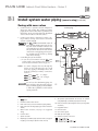
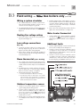
Wiring a system circulator
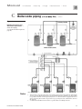
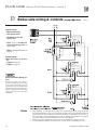
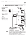
1. For combined systems, to activate a system circulator when the Boiler circulator operates, wire as
shown at bottom of Figure 17, page 30.
2. You must install a relay as shown. DO NOT wire in
parallel with the Boiler circulator. See CAUTION in
Figure 17.
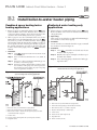
Routing line voltage wiring
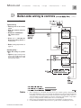
4. Install a summer/winter switch (Figure 19, item 7)
across terminals 1 and 2 to force fixed-temperature
operation during summer months. (When the
switch is closed, boiler will attempt to maintain
constant temperature.)
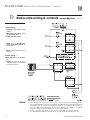
5. Route sensor wires through the grommeted hole at
right of the electrical entrance (see Figure 18).
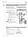
Water heater thermostat
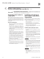
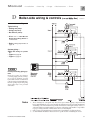
1. Route line voltage connections to the jacket openings shown in Figure 18.
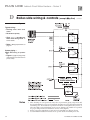
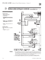
1. Connect PLUS water heater aquastat terminals
“C” and “1” to
Gas boiler low voltage terminal strip between terminals 3 and 4 (Figure 9,
item 3).
Low voltage connections
Additional limits
(Fig. 18)
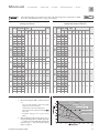
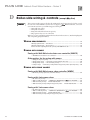
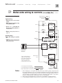
1. Connect low voltage wiring to low voltage terminal strip (Figure 19, page 32, item 1) as shown in
Figure 19 and the boiler wiring diagram.
2. Route all low voltage wires through grommeted
jacket opening to right of low voltage terminal strip,
as shown in Figure 18.
Room thermostat
(space heating)
1. For combined space heating/water heating systems,
connect Figure 19, item 2, room thermostat or end
switch (isolated contact only) between terminals 5 and 6.
2. Install thermostat on inside wall away from influences of drafts, hot or cold water pipes, lighting
fixtures, television, sunrays, or fireplaces.
3. Thermostat anticipator (if applicable):
1. Connect additional limit controls and interlocks
between the terminals shown in Figure 19.
2. Controls connected between terminals 6 and 7 (see Figure 19, item 4) will cause a soft lockout
(automatic reset). When limit(s) closes, boiler will
resume normal operation.
3. Controls connected between terminals 6 and 8
(see Figure 19, item 5). will cause a hard lockout
(manual reset). The boiler will only restart after
the Ultra display panel RESET switch is pressed.
Figure 18
Routing field wiring
a. If connected directly to boiler, set for 0.1 amps.
b. If connected to relays or other devices, set to match
total electrical power requirements of connected
devices. See device manufacturers’ specifications and
thermostat instructions for details.
Outdoor temperature sensor
1. Outdoor reset operation applies only to combined
space heating/water heating systems.
2. Connect outdoor temperature sensor (Figure 19,
item 6) between terminals 1 and 2 to enable outdoor reset operation of the
Gasboiler. If
fixed-temperature operation is required, do not
install outdoor sensor.
3. Mount sensor on exterior wall, shielded from direct sunlight or flow of heat or cooling from other
sources.
Part Number PLUS-E017-A/1206
31