1
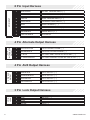
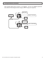
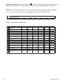
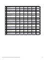
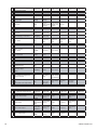
PROFESSIONAL
SERIES
Security and Remote Start Installation Guide
for models:
ca6554
2014 Voxx Electronics Corporation. All rights reserved.
1
Table of Contents
Before You Begin.......................................................................................... 4
Wire Connection Guide................................................................................ 5
4 Pin Main Harness.................................................................................... 7
6 Pin Start Harness.................................................................................... 8
6 Pin Output Harness............................................................................... 10
8 Pin Input Harness.................................................................................. 11
4 Pin Alternate Output Harness................................................................ 14
4 Pin AUX Output Harness....................................................................... 15
3 Pin Door Lock Output Harness.............................................................. 16
Additional Ports.......................................................................................... 20
Antenna / LED / Programming Port......................................................... 20
DBI Port.................................................................................................... 20
Telematic Interface Port............................................................................ 20
Set Up & Programming.............................................................................. 21
Transmitter Programming......................................................................... 21
Manual Feature Programming.................................................................. 21
Programming Feature Banks................................................................... 22
Tach Programming................................................................................... 25
Smart Tachless Mode............................................................................... 25
Adjusting the Shock Sensor..................................................................... 26
Testing the Shock Sensor......................................................................... 26
Chirp Delete - User Accessible................................................................. 26
Dome Light Delay / Theater Dimming...................................................... 26
2
ca6554 Install revA
Feature Descriptions.................................................................................. 27
Transmitter Button Functions................................................................... 35
Security Trigger Zones.............................................................................. 37
Remote Start Shutdown Diagnostics....................................................... 37
System Layout............................................................................................ 38
2014 Voxx Electronics Corporation. All rights reserved.
3
BEFORE YOU BEGIN
FOR AUTOMATIC TRANSMISSION VEHICLES ONLY.
PROFESSIONAL INSTALLATION
STRONGLY RECOMMENDED
Installation Precautions:
Roll down window to avoid locking keys in vehicle
during installation
Avoid mounting components or routing wires near
hot surfaces
Avoid mounting components or routing wires near
moving parts
Tape or loom wires under hood for protection and
appearance
Use grommets when routing wires through metal
surfaces
Use a Digital Multi Meter for testing and verifying
circuits. DO NOT USE A TEST LIGHT, OR
“COMPUTER SAFE PROBE” as these can set off air
bags or damage vehicle computers.
Technical Support (800) 421-3209
or go to
http://avxtech1.com
4
ca6554 Install revA
4 Pin Main Harness
4 PIN MAIN
WHITE/RED
PARKING LIGHT INPUT
2
WHITE
PARKING LIGHT OUTPUT
3
BLACK
GROUND
4
BROWN
SIREN OUTPUT ( + )
6 Pin Start Harness
6 PIN START
1
1
PURPLE
STARTER OUTPUT - MOTOR SIDE
2
RED
BATTERY 12V ( + )
3
ORANGE
ACCESSORY 1 ( + )
4
PINK/WHITE
IGNITION 2 ( + )
5
RED/WHITE
BATTERY 12V ( + )
6
PINK
IGNITION 1 ( + )
6 Pin Output Harness
6 PIN OUTPUT
1
BROWN/BLACK
HORN OUTPUT ( - )
2
BLUE/BLACK
START STATUS / ACTIVE OUTPUT ( - )
3
VIOLET/BLACK
AUX 1 OUTPUT ( - )
4
RED/WHITE
TRUNK RELEASE OUTPUT ( - )
5
LT GREEN/BLACK
FACTORY DISARM / PULSE BEFORE START ( - )
6
ORANGE
GROUND WHEN ARMED OUTPUT ( - )
2014 Voxx Electronics Corporation. All rights reserved.
5
8 Pin Input Harness
8 PIN INPUT
INSTANT TRIGGER INPUT ( - )
GREEN
DOOR TRIGGER INPUT ( - )
3
PURPLE
DOOR TRIGGER INPUT ( + )
4
WHITE/BLUE
EXTRENAL START INPUT ( - )
5
GRAY
HOOD PIN INPUT ( - )
6
GRAY/RED
PARKING BRAKE INPUT ( - )
7
BROWN/RED
BRAKE INPUT ( + )
8
PURPLE/WHITE
TACH INPUT
1
BLACK/YELLOW
PULSE DURING CRANK ( - )
2
GREEN/WHITE
PULSE AFTER SHUTDOWN ( - )
3
LT BLUE
FACTORY ARM / PULSE AFTER START ( - )
4
LT GREEN/BLACK
FACTORY DISARM / PULSE BEFORE START ( - )
4 Pin AUX Output Harness
4 PIN AUX
OUTPUT
1
PINK/BLACK
AUX 5 OUTPUT ( - )
2
ORANGE/BLACK
AUX 4 OUTPUT ( - )
3
GRAY/BLACK
AUX 3 OUTPUT ( - )
4
WHITE/BLACK
AUX 2 OUTPUT ( - )
3 Pin Lock Output Harness
3 PIN
LOCK
6
BLUE/WHITE
2
4 Pin Alternate Output Harness
4 PIN
ALTERNATE
OUTPUT
1
1
BLUE
2
OPEN
3
GREEN
UNLOCK ( - )
LOCK ( - )
ca6554 Install revA
4 Pin Main Harness
1
WHITE/RED
PARKING LIGHT INPUT
2
WHITE
PARKING LIGHT OUTPUT
Locate the parking light output wire at the vehicle’s light switch.
Positive switching Parking Lights:
Verification: This wire registers positive voltage when the parking lights are turned on.
Connect the WHITE/RED wire to a 15 Amp max fused battery source.
Connect the WHITE wire to the parking light output wire.
Negative switching Parking Lights:
Connect the WHITE/RED wire to a good chassis ground.
Connect the WHITE wire to the parking light output wire.
3
BLACKGROUND
Connect the BLACK wire to a solid chassis ground point using a ring terminal and
self tapping screw (not supplied). Scrape away paint from the grounding point to
ensure a good connection. The recommended grounding point is a metal surface in
the driver’s side kick panel area.
NOTE: Do not ground the BLACK wire with any other vehicle components.
4
Locate a suitable mounting location in the engine compartment for the siren, away
from moving parts.
With the bell of the siren aiming downwards, secure the siren in place using self
tapping screws, being careful not do drill into any hoses, wiring or components.
Connect the BLACK siren wire to a chassis ground using a ring terminal and self
tapping screw (not supplied).
Route the BROWN siren output wire from the control module through the firewall and
connect to the RED wire on the siren.
BROWN
SIREN OUTPUT ( + )
NOTE: Be sure to loom the siren wires, and seal the grommet.
2014 Voxx Electronics Corporation. All rights reserved.
7
6 Pin Start Harness
1
PURPLE
Locate the vehicle starter wire.
STARTER OUTPUT ( + )
Verification: This wire registers voltage only when the key is turned to the START position. Cut the vehicle’s starter wire in half when installing the starter kill relay.
Verification after starter wire is cut:
KEY SIDE of starter wire registers voltage when the key is turned to the START position.
MOTOR SIDE of starter wire registers no voltage.
Connect the PURPLE wire to the vehicle starter wire, use the MOTOR SIDE of the vehicle starter wire when installing the starter kill relay.
2
8
RED
BATTERY 12V ( + )
Locate 1 of the vehicle’s constant 12 Volt battery wires at the ignition switch.
Verification: This wire will register ( + ) voltage in all positions of the ignition switch.
Connect the RED wire to the constant 12 Volt battery wire.
NOTE: Remove all fuses until all connections are made.
3
Locate the vehicle’s accessory wire at the ignition switch.
Connect the ORANGE wire to the vehicle’s accessory wire.
ORANGE
ACCESSORY 1 ( + )
Verification: This wire registers voltage when the key is turned to ACC (Accessory) and the ON (or RUN) position. The voltage drops out when the key is turned to the START (or CRANK) position.
ca6554 Install revA
4
PINK/WHITE
IGNITION 2 ( + )
Locate the vehicle’s 2nd ignition wire at the ignition switch (if equipped).
Connect the PINK/WHITE wire to the vehicle’s ignition 2 wire.
Programmable output: IGN, ACC, Start.
5
Locate 1 of the vehicle’s constant 12 Volt battery wires at the ignition switch.
Verification: This wire will register ( + ) voltage in all positions of the ignition switch.
Connect the RED/WHITE wire to the constant 12 Volt battery wire.
NOTE: Remove all fuses until all connections are made.
6
Verification: This wire registers voltage when the key is turned to the ON (or RUN) position, but not the ACC (Accessory) position. The voltage does not drop out when the key is turned to the START (or CRANK) position.
RED/WHITE
PINK
BATTERY 12V ( + )
IGNITION 1 ( + )
Locate the vehicle’s ignition wire at the ignition switch.
Verification: This wire registers voltage when the key is turned to the ON (or RUN) position. The voltage does not drop out when the key is turned to the START (or CRANK) position.
Connect the PINK wire to the vehicle’s Ignition wire.
This wire is also used for Ignition 1 Output.
2014 Voxx Electronics Corporation. All rights reserved.
9
6 Pin Output Harness
1
BROWN/BLACK
HORN OUTPUT ( - )
Locate the vehicle’s horn wire.
Connect the BROWN/BLACK wire to the vehicle’s horn wire. This is a low current
output, 200mA.
2
This wire provides a ( - ) 200mA output when the remote start function is activated
and remains until 4 seconds after the remote start is shutdown. If this wire will be
used for multiple application’s a 1 amp diode is required in-line with the stripe facing
the control module.
3
Verification: This wire will register at positive voltage and register ground when the horn switch is pressed.
BLUE/BLACK
VIOLET/BLACK
START STATUS / ACTIVE OUTPUT ( - )
AUX 1
This wire provides a ( - ) 200mA output capable of driving relays. For Control of
optional accessories (i.e. Power Window/Sunroof, etc.).
To activate refer to the transmitter button configuration chart. Please refer to the
selectable options for timing.
4
RED/WHITE
TRUNK RELEASE OUTPUT ( - )
Locate the vehicle’s trunk release wire at the trunk release switch.
Verification: This wire will register either positive voltage or ground when the trunk release is activated.
This is a low current 200mA output and in configurable in option programming.
10
ca6554 Install revA
5
LT GREEN/BLACK
FACTORY DISARM /
PULSE BEFORE START ( - )
This wire will supply a ( - ) 200mA pulse both upon disarming the system and when
the remote start feature is activated. Locate the factory perimeter alarm disarm wire
from the key cylinder inside the drivers door.
Connect the LIGHT GREEN/BLACK wire to the factory alarm disarm wire.
6
This wire will have a continuous ( - ) 500mA output when the system is Armed.
This wire is typically used for controlling the starter interrupt relay as well as window
modules or additional sensors.
This output can be configured in option programming.
Verification: This wire registers ground if the key is turned to the unlock position in the driver’s door cylinder.
ORANGE
GROUND WHEN ARMED OUTPUT ( - )
8 Pin Input Harness
1
BLUE/WHITE
INSTANT TRIGGER INPUT ( - )
This wire is a GROUND input for an external sensor or secondary pin switch.
Verification: This wire when connected will trigger the security system.
2
GREEN
DOOR TRIGGER INPUT ( - )
Locate the vehicle’s dome light or door pin switch wire.
Connect the GREEN wire to the vehicle’s negative door input wire(s).
NOTE: Certain vehicles may require multiple connections. Refer to vehicle
application guide.
Verification: This wire will register ground (NEG) when the door is opened and the interior light is on. This wire will register positive voltage when the door is closed and the interior light is off.
2014 Voxx Electronics Corporation. All rights reserved.
11
3
PURPLE
DOOR TRIGGER INPUT ( + )
Locate the vehicle’s dome light or door pin switch wire.
Verification: This wire will register positive voltage (POS) when the door is opened and the interior light is on. This wire will register ground or “0” Volts when the door is closed and the interior light is off.
Connect the PURPLE wire to the vehicle’s positive door input wire(s).
NOTE: Certain vehicles may require multiple connections. Refer to vehicle
application guide.
4
WHITE/BLUE
EXTERNAL START INPUT ( - )
This wire will activate the Remote Start function when a GROUND pulse is applied to
it from an external device.
5
Install a Hood Pin Switch and connect to the GRAY wire. This connection is required
for Remote Start.
Connect the GRAY wire to the hood pin.
NOTE: Be sure to loom the wire, and seal the grommet.
6
GRAY
HOOD PIN INPUT ( - )
Verification: This wire when connected will register ground when the vehicle’s hood is opened.
GRAY/RED PARKING BRAKE INPUT ( - )
Locate the vehicle’s parking brake wire.
12
Verification: This wire will register ground when the vehicle’s PARKING
BRAKE is engaged.
NOTE: The following connection is required for Manual Transmission Mode.
ca6554 Install revA
7
BROWN/RED
BRAKE INPUT ( + )
Locate the vehicle’s brake light wire at the brake pedal mounted switch. This
connection is required for remote start.
Verification: This wire registers positive voltage when the brake pedal is pressed.
Connect the BROWN/RED wire to the vehicle’s brake light wire.
8
PURPLE/WHITE
TACH INPUT
Locate the vehicle’s ignition coil or fuel injector in the engine compartment.
Verification: Test using the following procedure:
1.
2.
3.
4.
5.
Set voltmeter to AC VOLTS.
Attach positive lead of a volt meter to a constant 12 volt source.
Attach negative lead of a volt meter to the wire to be tested.
Start the engine.
Have someone press on the gas pedal slightly as you monitor the meter. If connected to the correct wire, the voltage reading will increase as the engine’s RPM increases.
Connect the PURPLE/WHITE wire to the negative side of the vehicle ignition coil or
fuel injector.
2014 Voxx Electronics Corporation. All rights reserved.
13
4 Pin Alternate Output Harness
1
LT GREEN/BLACK
FACTORY DISARM /
PULSE BEFORE START ( - )
This wire will supply a ( - ) 200mA pulse both upon disarming the system and when
the remote start feature is activated. Locate the factory perimeter alarm disarm wire
from the key cylinder inside the drivers door.
This output can be configured in option programming.
2
Verification: This wire registers ground if the key is turned to the unlock position in the driver’s door cylinder.
LT BLUE
FACTORY ARM /
PULSE AFTER START ( - )
This wire will supply a ( - ) 200mA pulse both upon arming the system and upon
successful completion of the remote start activation sequence and is typically used to
re-lock the vehicle’s doors upon remote start if necessary.
This output can be configured in option programming.
3
This wire will supply a ( - ) 200mA pulse after the remote start shuts down. This
is typically used to re-lock the vehicle’s doors if they unlock upon remote start
shutdown. It can also be used to pulse a door pin-switch wire to prevent the vehicle’s
accessories from remaining on after remote start shutdown.
This output can be configured in option programming.
4
GREEN/WHITE
BLACK/YELLOW
PULSE AFTER SHUTDOWN ( - )
PULSE DURING CRANK ( - )
Locate the vehicle’s second starter (crank) wire at the ignition switch. (if equipped)
This wire will supply a ( - ) 200mA output and can be configured in option
programming.
14
Verification: This wire registers voltage only in the start (crank) position of the ignition switch.
ca6554 Install revA
4 Pin AUX Output Harness
1
PINK/BLACK
AUX 5
This wire provides a ( - ) 200mA output capable of driving relays. For Control of
optional accessories (i.e. Power Window/Sunroof, etc.).
To activate refer to the transmitter button configuration chart. Please refer to the
selectable options for timing.
2
ORANGE/BLACK
AUX 4
This wire provides a ( - ) 200mA output capable of driving relays. For Control of
optional accessories (i.e. Power Window/Sunroof, etc.).
To activate refer to the transmitter button configuration chart. Please refer to the
selectable options for timing.
3
GRAY/BLACK
AUX 3
This wire provides a ( - ) 200mA output capable of driving relays. For Control of
optional accessories (i.e. Power Window/Sunroof, etc.).
To activate refer to the transmitter button configuration chart. Please refer to the
selectable options for timing.
4
WHITE/BLACK
AUX 2
This wire provides a ( - ) 200mA output capable of driving relays. For Control of
optional accessories (i.e. Power Window/Sunroof, etc.).
To activate refer to the transmitter button configuration chart. Please refer to the
selectable options for timing.
2014 Voxx Electronics Corporation. All rights reserved.
15
3 Pin Lock Output Harness
1
BLUE
UNLOCK ( - )
3
GREEN
LOCK ( - )
The door lock / unlock outputs are designed to control several different types of
systems which may require additional parts. Please review the wire and location
chart to see which type of door lock system is in your vehicle. The most common
types are shown in the following diagrams.
These wires supply a ( - ) 500mA output.
Negative Switching Locks
All Door Lock and Unlock: Locate the lock / unlock wire at the vehicle’s lock / unlock
switch.
Connect the GREEN and BLUE wires shown in the diagram below.
Verification: These wires will register ground when the Lock and Unlock switches are activated.
Negative Locks:
GREEN ( - ) Lock Output
Lock
Vehicle Door Lock
Control Relays
Unlock
BLUE ( - ) Unlock Output
16
ca6554 Install revA
Positive Switching Locks
All Door Lock and Unlock: Locate the lock / unlock wire at the vehicle’s lock / unlock
switch.
Connect the GREEN and BLUE wires shown in the diagram below.
Verification: These wires will register positive voltage when the Lock and Unlock switches are activated.
Positive Locks:
Fused +12 Volt
Battery Souce
87
86
87a
GREEN ( - ) Lock Output
85
30
Lock
Fused +12 Volt
Battery Souce
Vehicle Door Lock
Control Relays
87
Unlock
86
87a
85
BLUE ( - ) Unlock Output
30
Reverse Polarity Locks (5-Wire Door locks)
All Door Lock and Unlock: Locate the lock / unlock wire at the vehicle’s lock / unlock
switch.
Connect the GREEN and BLUE or BLUE/GREEN wires shown in the diagram below
using (2) SPDT relays (not supplied).
Verification: These wires will rest at ground and register positive voltage when the Lock and Unlock switches are activated.
Reverse Polarity Locks:
Fused +12 Volt
Battery Souce
87
86
87a
85
GREEN ( - ) Lock Output
30
X
Lock
To Door Lock Motor
Cut
Unlock
Fused +12 Volt
Battery Souce
87
87a
86
85
BLUE ( - ) Unlock Output
30
X
To Door Lock Motor
Cut
2014 Voxx Electronics Corporation. All rights reserved.
17
Negative Multiplexed Locks
All Door Lock and Unlock: Locate the lock / unlock wire at the vehicle’s lock / unlock
switch.
Connect the GREEN and BLUE or BLUE/GREEN wires shown in the diagram below
using (2) SPDT relays (not supplied).
Verification: This wire will show variable ground when the switch is activated. Please consult the wire and location chart for specific resistor values for your vehicle.
Multiplex Locks:
Ground
87
87
GREEN ( - ) Lock Output
86
87a
85
Fused +12 Volt
Battery Source
87a
86
BLUE ( - ) Unlock Output
85
30
30
Resistor
Lock
Vehicle Door Lock
Control Relays
Unlock
Positive Multiplexed Locks
All Door Lock and Unlock: Locate the lock / unlock wire at the vehicle’s lock / unlock
switch.
Connect the GREEN and BLUE or BLUE/GREEN wires shown in the diagram below
using (2) SPDT relays (not supplied).
Verification: This wire will show variable positive voltage when the switch is activated. Please consult the wire and location chart for specific resistor values for your vehicle.
Multiplex Locks:
87
87
GREEN ( - ) Lock Output
86
87a
85
Fused +12 Volt
Battery Source
Lock
86
87a
85
BLUE ( - ) Unlock Output
30
30
Resistor
Vehicle Door Lock
Control Relays
Unlock
18
ca6554 Install revA
Adding Aftermarket Actuators
After installing aftermarket actuators, (not supplied). Connect the GREEN and BLUE
wires shown in the diagram below using (2) SPDT relays (not supplied).
Fused +12 Volt
Battery Source
87
Door Lock
Actuator
86
87a
30
Chassis
Ground
M
Fused +12 Volt
Battery Source
87
86
87a
30
GREEN ( - ) Lock Output
85
BLUE ( - ) Unlock Output
85
Chassis
Ground
2014 Voxx Electronics Corporation. All rights reserved.
19
Additional Ports
Antenna / LED / Programming Port
Mount the supplied antenna/receiver to a clear spot on the vehicle’s windshield that
will not block the driver’s vision. A good location is usually high on the windshield
near the rear view mirror. Be careful not to mount the antenna/receiver on any
metallic window film, as this will effect system range. Route the antenna/receiver
cable to the control module and plug into the antenna port.
Data Bus Interface Port
This 4 pin port is used for Flashlogic Door Lock and Transponder Databus Interfaces
to communicate with the vehicle’s Databus. When using the DBI port to control the
Flashlogic Door Lock and Transponder Interface modules the following options may
be available. Please refer to the D2D (Data to Data) function list available per vehicle
on the tech service web site.
Tach Input
Brake Safety Shut Down
Door Trigger
Trunk/Hatch Open
Door Lock Control
Passlock / Passkey Interface (GM Only)
Dome Light Supervision
Transponder Interface Activation
Factory Alarm Arm / Disarm
Diesel Glow Plug Input
Manual Arm / Disarm Inputs (factory keyless controls system)
Telematic Interface Port
This 4 pin port is used for telematic Interface accessories, such as Car Connection
Pro, which can control some of the following features.
Door Lock Control
Trunk Release
Sliding Doors
AUX Output
Car Find
Remote Start
20
ca6554 Install revA
Set Up & Programming
Transmitter Programming - Feature Bank 1
1. Turn the ignition ON.
2. Press and hold the valet/override button.
3. Within 10 seconds the system will chirp (3) three times.
4. Press 1 button of each transmitter you wish to program.
5. The system will respond with 1 chirp for each accepted transmitter.
6. Pressing the override button at anytime during programming will advance to the next bank.
NOTE: The system will exit transmitter programming after 15 seconds of inactivity.
NOTE: This system has 1 button programming which programs all channels of the
system.
NOTE: The system will hold up to 4 transmitters in memory, programming a 5th
transmitter will erase the oldest transmitter in memory.
NOTE: This system has PTN - Programmed Transmitter Notification. Each time the
ignition is turned ON, the LED will flash the number of transmitters programmed to the
system.
Transmitter programming for 2 Car Mode *2 way system only:
1.
Enter the transmitter into 2 Car Mode. (Refer to transmitter operation in the owners manual for 2 car operation)
2. Follow the steps above for transmitter programming.
NOTE: 2 car mode requires an additional security system installed in a second
vehicle.
Manual Feature Programming - Feature Bank 2 - 5
1. Turn the ignition ON.
2. Press and hold the valet/override button.
3. Within 10 seconds the system will chirp (3) three times.
4. Use the valet/override button to advance through each option bank. For feature programming advance to Feature Bank 2, 3, 4 or 5, which is (4) four, (5) five, (6) six and (7) seven chirps.
5. Use the transmitter
button to scroll through the selections in each feature bank, the system will chirp to match the feature number.
6. Press the transmitter
button to change the desired feature. The LED will flash indicating the changed feature.
2014 Voxx Electronics Corporation. All rights reserved.
21
Defaulting All Features: Pressing the
banks will default all features and
NOTE: The system will remain in feature programming mode as long as the ignition
is on, there is no time limit. To exit programming turn the IGNITION OFF.
button anytime while in any of the feature
return you to feature bank 2 - 4 chirps.
Feature Bank 1 - 3 Chirps
Transmitter Programming
22
Refer to transmitter programming.
Feature Bank 2 - 4 Chirps
Security Control
1 LED Flash
1
Silent Choice
ON
OFF
2
Passive Locks
Active
Passive
2 LED Flash
3
Passive Arming
Active
Passive
4
Siren / Horn - Arm/Disarm Chirps
Siren / Horn
Siren
5 Siren Duration
30 Seconds
60 Seconds
6
ON
OFF
ON
Security
7
Anti-Hijack Mode
OFF
8
Orange - Ground w/ Armed Output
Ground While Ground While
Disarmed
Armed
9
DBI Port Protocol
DBI Protocol
ADS Protocol
10
Arm/Disarm
Chirp / Parking Light Pattern
Standard:
2 - Arm
1 - Disarm
Inverted:
1 - Arm
2 - Disarm
3 LED Flash
4 LED Flash
5 LED Flash
6 LED Flash
Horn
ca6554 Install revA
Feature Bank 3 - 5 Chirps
Output Control
1 LED Flash
2 LED Flash
3 LED Flash
4 LED Flash
5 LED Flash
1
Extended Lock Pulse
1 Second
3.5 Seconds
1 Second
Lock, Double
Pulse Unlock
30 Second
Lock, Double
Pulse Unlock
Double Pulse
Lock, 1
Second Unlock
2
Factory Disarm
Lt Green / Black (6 Pin harness)
Factory
Disarm
1Sec Pulse
2nd Unlock
Factory Disarm Factory Disarm Factory Disarm
/ Start Status 350mS Pulse 500mS Pulse
3
Ignition Controlled Locks
OFF
Lock and
Unlock
Lock Only
Unlock Only
4
Trunk Output Timing
Red / White Output
1 Second
Pulse
10 Seconds
20 Seconds
Latched until
IGN ON
Latched ON
until Button
Press
5
Horn Output Timing
16mS
10mS
30mS
40mS
50mS
6
Real Panic
ON
OFF
7
AUX 1
Violet / Black Output
1 Second
Pulse
Latched
Latched until
IGN ON
Dome Light
Output
Defrost Output Defrost Output
Single Pulse
Latched 5 Min
After Start
After Start
8
AUX 2
White / Black Output
1 Second
Pulse
Latched
Latched until
IGN ON
10 Second
10 Second
Pulse with
Pulse with Arm
Disarm
9
AUX 3
Gray / Black Output
1 Second
Pulse
Latched
Latched until
IGN ON
10 Second
10 Second
Pulse with
Pulse with Arm
Disarm
10
AUX 4
Orange / Black Output
1 Second
Pulse
Latched
Latched until
IGN ON
10 Second
10 Second
Pulse with
Pulse with Arm
Disarm
11
AUX 5
Pink / Black Output
1 Second
Pulse
Latched
Latched until
IGN ON
10 Second
10 Second
Pulse with
Pulse with Arm
Disarm
2014 Voxx Electronics Corporation. All rights reserved.
6 LED Flash
23
Feature Bank 4 - 6 Chirps
Remote Start Control
1 LED Flash
2 LED Flash
1
RF Start Chirp
ON
OFF
2
Run Time
15 Minutes
5 Minutes
3
Running Lights
Steady
Flashing
Tach Mode
Tach
Tachless
Hybrid (Crank
(Crank Average Average / NO
/ Voltage)
Voltage)
Low
4
5
Voltage Level
High
6
Crank Time
1.0 Seconds
0.8 Seconds
7
Crank Averaging / Crank Time
Averaging
Preset Time
8
Gas / Diesel
Gas
10 Second
Delay
9
Single / Double Press Start
Double Press Single Press
Ignition 2 Output
10
Pink / White
Ignition
Accessory
11 2 or 3 Hour Start
3 Hour
2 Hour
12 Turbo Timer
OFF
1 Minute
13 Transmission Mode
Automatic
Manual
14 Temperature Start
OFF
4 LED Flash
5 LED Flash
6 LED Flash
10 Minutes
20 Minutes
45 Minutes
60 Minutes
DBI Port
1.5 Seconds
2.0 Seconds
4.0 Seconds
15 Second
Delay
20 Second
Delay
45 Second
Delay
Start / Crank
3 Minute
5 Minute
14F
5F
-4F
15
Accessory Output
Orange
Accessory
Ignition
Start / Crank
16
Pulse Additional Outputs when
Unlock is Pressed
OFF
IGN, ACCY,
GWR
IGN, ACCY,
GWR - Pulse
After Shutdown
OFF
Unlock before
Start, Lock
After Start
Unlock Before
Start
Lock After
Start
Lock After
Shutdown
Feature Bank 5 - 7 Chirps
4 Pin Alternate Output Control
1 LED Flash
2 LED Flash
3 LED Flash
4 LED Flash
5 LED Flash
1
Lt Green / Black Output
Pulse Before
Ground While
Start / During
Running
Unlock
Ignition
Accessory
Pulse During
Crank
2
Lt Blue Output
Pulse After
Ground While
Start / During
Running
Lock
Ignition
Accessory
Pulse During
Crank
3
Green / White Output
Pulse After
Shutdown
Ground While
Running
Ignition
Accessory
Pulse During
Crank
4
Black / Yellow Output
Pulse During
Crank
Ground While
Running
Ignition
Accessory
Door Lock Control During Remote
17 Start
Blue & Green Lock Output Wires
24
3 LED Flash
6 LED Flash
ca6554 Install revA
Tach Programming
The unit will not operate unless tach is programmed or tachless option is
turned ON. If an attempt is made to start the vehicle via the remote start without first
programming tach, the unit will flash the parking lights 7 times indicating tach has not
been learned and stored. If the tach rate is not properly programmed to the specific
vehicle, the unit may not realize that the vehicle is running in certain instances and
re-engage the starter motor.
The Remote Start unit will learn the tach rate of most vehicle’s single coil, multiple coil
packs, or single injector. To learn tach:
1. Turn the ignition key to the ON position.
2. Press and release the valet/override button 3 times.
3. Immediately turn the ignition key OFF.
4. Press and hold the valet/override button, then start the vehicle using the key.
5. When the unit senses the tach signal, the parking lights will begin to flash.
6. Allow the vehicle to settle to a normal idle speed.
7. Release the valet/program push-button switch. The parking lights will turn on for 2 seconds and 1 long chip will indicate that the learned tach signal is stored and the unit has exited tach learn mode.
NOTE: If the unit fails to learn tach rate due to an improper tach connection or a
poor tach source, the parking lights will not flash. To correct this situation, locate and
connect the PURPLE/WHITE wire to the proper tach signal, and then repeat the tach
learn routine.
Smart Tachless Mode
Smart Tachless Mode is available only if a tach signal has never been learned to the
system and when activated will automatically change the Tach Mode feature in option
programming to Tachless without the need to enter the feature programming mode.
1.
Activate the remote start. The parking lights should begin flashing 7 times indicating no tach signal has been learned.
Within the 7 flash time period, press and hold the
2.
button.
3. The system will chirp 1 time indicating the system is now in tachless mode.
2014 Voxx Electronics Corporation. All rights reserved.
25
Adjusting the Shock Sensor
1. Increase sensitivity by turning the adjustment dial clockwise.
2. Decrease sensitivity by turning the adjustment dial counter clockwise.
Testing the Shock Sensor
Arm the system and wait 6 seconds for the zone to stabilize, then firmly strike the
vehicles bumper.
Chirp Delete - User Accessible
System ARM/DISARM chirps can be toggled ON or OFF without entering the
programming feature banks.
1. Turn the ignition ON then OFF.
2. Press and release the valet/programming button 3 times. The system will respond with 1 chirp for ON or 2 chirps for OFF.
Dome Light Delay / Theater Dimming
The system can be programed to delay arming after the lock button is pressed
(60 second max) for vehicles with a dome light delay or theater dimming feature.
Once programed the system will ‘learn’ the timing of the dome light delay and add 2
seconds before arming.
1. Close all doors with ignition off.
2. Using the transmitter press LOCK, UNLOCK, LOCK ,UNLOCK, LOCK , UNLOCK, LOCK. The LED will light solid to indicate the system has entered DOME DELAY LEARN MODE.
3.
26
Immediately OPEN then CLOSE the door WITHOUT disarming the system. The system will then monitor the door trigger wire. Once the dome light turns off, the system will then add 2 seconds and then exit the learning mode.
4. The LED will begin to flash indicating the system has exited the learning mode and is now armed.
ca6554 Install revA
Feature Descriptions
Feature Bank 2 - Security
1 - Silent Choice: Controls the normal arm/disarm chirps of the security system.
ON - Silent arming/disarming upon first press of lock/unlock, pressing lock/
unlock a second time will activate the arm/disarm chirps respectively. The system will only sound the arm/disarm chirps upon a second press of the lock/unlock buttons.
OFF - normal arm/disarm chirps upon the first press of lock/unlock.
2 - Passive Locks: Determines manual or automatic locking of the vehicle’s doors.
Active - Requires use of the transmitter to lock the vehicle’s doors.
Passive - Automatically locks the vehicle’s doors 1 minute after the last door is closed. Note: For Passive Locks, feature #3 Passive Arming must also be set to passive
3 - Passive Arming: Determines manual or automatic locking of the vehicle’s doors.
Active - Requires use of the transmitter to arm the security system.
Passive - Automatically arms the security system 1 minute after the last door is closed.
4 - Siren / Horn: This feature selects which output(s) will sound the system’s
arm/disarm chirps. This feature does not effect the triggered state of the security
system and during a triggered cycle, both the siren and horn outputs will activate
respectively.
5 - Siren Duration: This feature controls the length of time the system will sound
when triggered.
6 - Security: Controls security functionality - ON / OFF.
ON - Full security functionality.
OFF - The security system does not trigger. Panic, Remote Start and all other convenience features operate as normal.
7- Anti-Hijack Mode: Controls car jack mode - ON / OFF.
OFF - Standard security system operation.
ON - Enables Car Jack mode functionality as described in the owners manual.
2014 Voxx Electronics Corporation. All rights reserved.
27
8 - Ground While Armed / Orange Output: Controls the output of the orange wire.
This wire will either supply a ( - ) output when armed OR disarmed.
9 - DBI Port Protocol: Determines the protocol type in which the DBI port uses to
interface with external modules.
DBI Protocol
ADS Protocol
10 - Arm/Disarm Chirp / Parking Light Pattern: Determines the number of chirps
and parking light flashes when the system is armed/disarmed.
Standard - 2 chirps/light flashes with arm, 1 chirp/light flash with disarm.
Inverted - 1 chirp/light flash with arm, 2 chirps/light flashes with disarm.
Feature Bank 3 - Output Control
1 - Extended Lock Pulse: Controls the timing of the BLUE and GREEN lock output
wires.
1 Second - Single 1 second lock pulse, single 1 second unlock pulse.
3.5 Seconds - Single 3.5 second lock pulse, single 3.5 second unlock pulse.
1 Second Lock, Double Pulse Unlock - Single 1 second lock pulse, double 1 second unlock pulse.
30 Second Lock, Double Pulse Unlock - Single 30 second lock pulse, double 1 second unlock pulse.
Double Pulse Lock, 1 Second Unlock - Double 1 second lock pulse, single 1 second unlock pulse.
2 - Factory Disarm: Controls the timing of the LT. GREEN/BLACK factory disarm
wire on the 6 pin output harness only and does not change the output of the factory
disarm wire on the 4 pin alternate output harness.
Factory Disarm - Single 1 second pulse with unlock and remote start activation.
2nd Unlock - Same output as unlock with 2nd press of unlock.
Factory Disarm / Start Status - Single 1 second pulse with unlock and continuous ( - ) output during the remote start cycle.
Factory Disarm - Single 350mS second pulse with unlock and remote start activation.
Factory Disarm - Single 500mS second pulse with unlock and remote start activation.
28
ca6554 Install revA
3 - Ignition Controlled Locks: Control of door locks when the ignition is cycled ON
or OFF.
OFF - Door locks not activated by ignition.
Lock and Unlock - Doors lock when ignition is turned on and unlock when ignition is turned off.
Lock Only - Doors lock when ignition is turned on.
Unlock Only - Doors unlock when ignition is turned off.
4 - Trunk Output Timing - Red/White Output: Controls the output timing/type of the
RED/WHITE output.
1 Second Pulse - 1 second pulse output.
10 Second - Continuous output for 10 seconds.
20 Seconds - Continuous output for 20 seconds.
Latched until IGN ON - Continuous output until the vehicle’s ignition is turned ON.
Latched ON until Button Press - Continuous output until the activation button is pressed again.
5 - Horn Output Timing: Control the minimum horn pulse time in milli seconds,
some vehicle will require a longer pulse to activate the factory horn.
16mS 10mS30mS40mS50mS
6 - Real Panic: Controls the horn output when the system is triggered.
ON - Randomized horn honks when panic is triggered.
OFF - Standard pattern horn honks when panic is triggered.
7 - AUX 1: Controls the VIOLET/BLACK AUX 1 output activation type and timing.
1 Second Pulse - Single 1 second pulse.
Latched - Output stays active until button is pressed again.
Latched until IGN ON - Output stays active until the ignition is turned on.
Dome Light Output - Output used for illuminated entry and is not controlled by the AUX 1 function of the transmitter.
Defrost Output Single Pulse - Single 1 second pulse after start
Defrost Output Latched 5 Minutes - 5 minute continuous output after remote start.
2014 Voxx Electronics Corporation. All rights reserved.
29
8 - AUX 2: Controls the WHITE/BLACK AUX 2 output activation type and timing.
1 Second Pulse - Single 1 second pulse.
Latched - Output stays active until button is pressed again.
Latched until IGN ON - Output stays active until the ignition is turned on.
10 Second Pulse with Arm - Output stays active for 10 seconds with press of lock button.
10 Second Pulse with Disarm - Output stays active for 10 seconds with press of unlock button.
9 - AUX 3: Controls the GRAY/BLACK AUX 3 output activation type and timing.
1 Second Pulse - Single 1 second pulse.
Latched - Output stays active until button is pressed again.
Latched until IGN ON - Output stays active until the ignition is turned on.
10 Second Pulse with Arm - Output stays active for 10 seconds with press of lock button.
10 Second Pulse with Disarm - Output stays active for 10 seconds with press of unlock button.
10 - AUX 4: Controls the ORANGE/BLACK AUX 4 output activation type and timing.
1 Second Pulse - Single 1 second pulse.
Latched - Output stays active until button is pressed again.
Latched until IGN ON - Output stays active until the ignition is turned on.
10 Second Pulse with Arm - Output stays active for 10 seconds with press of lock button.
10 Second Pulse with Disarm - Output stays active for 10 seconds with press of unlock button.
11 - AUX 5: Controls the PINK/BLACK AUX 5 output activation type and timing.
1 Second Pulse - Single 1 second pulse.
Latched - Output stays active until button is pressed again.
Latched until IGN ON - Output stays active until the ignition is turned on.
10 Second Pulse with Arm - Output stays active for 10 seconds with press of lock button.
10 Second Pulse with Disarm - Output stays active for 10 seconds with press of unlock button.
30
ca6554 Install revA
Feature Bank 4 - Remote Start Control
1 - RF Start Chirp: Turns remote start activation confirmation chirps ON or OFF.
2 - Run Time: Controls the time in minutes that the vehicle will stay running under
control of the remote start until the system times out. The system may also be shut
down at any time by use of the transmitter or system shutdowns.
3 - Running Lights: Controls the WHITE parking light output wire during remote
start.
Steady - Parking lights constant during the remote start cycle.
Flashing - Parking lights flash at a slow pace during the remote start cycle.
4 - Tach Mode: Determines how the system monitors the engine running during
remote start.
Tach - Hard wired directly to the tach wire of the vehicle to monitor AC voltage.
Tachless (Crank Average/Voltage) - Determines crank time by averaging the last 8 times the vehicle was started with the key and then monitors the change in voltage after remote start.
Hybrid (Crank Average / No Voltage) - Determines crank time by averaging the last 8 times the vehicle was started with the key.
DBI Port - Monitors the vehicle’s tach rate through an interface module connected to the DBI port.
5 - Voltage Level: The voltage variance for remote start when set to tachless. (see
tach mode)
HIGH - The variance in battery voltage from before the remote start is activated to after the engine is running must be greater than 0.5 volts.
LOW - The variance in battery voltage from before the remote start is activated to after the engine is running may be less than 0.5 volts.
6 - Crank Time: Preset output times for the PURPLE starter wire.
7 - Crank Average / Crank Time: The length of time in which the remote start will
crank the vehicle’s starter.
Crank Average - Determines crank time by averaging the last 8 times the vehicle was started with the key.
Preset Time - Preset starter output time. (see crank time)
2014 Voxx Electronics Corporation. All rights reserved.
31
8 - Gas / Diesel: Selects engine type and delay time for the starter output wire during
remote start activation.
Gas - Gasoline engine, no delay for the starter output wire.
10 Second Delay - Diesel engine, delays the starter output wire for 10 seconds after the ignition has been powered up by the remote start.
15 Second Delay - Diesel engine, delays the starter output wire for 15 seconds after the ignition has been powered up by the remote start.
20 Second Delay - Diesel engine, delays the starter output wire for 20 seconds after the ignition has been powered up by the remote start.
45 Second Delay - Diesel engine, delays the starter output wire for 45 seconds after the ignition has been powered up by the remote start.
9 - Single / Double Pulse Start: Switches the remote start activation between a
single or double press from the transmitter.
10 - Ignition 2 Output Pnik/White: Programmable high current output.
Ignition 2 - Output becomes active with the same timing as the ignition output and does not drop out during crank.
Accessory - Output becomes active with the same timing as the accessory output, drops out during crank.
Start / Crank - Output becomes active with the same timing as the starter output wire, during crank only.
11 - 2 or 3 Hour Start: When activated, the remote start will activate and run for the
programmed time and shut down every 2 or 3 hours.
12 - Turbo Timer: When activated, the vehicle will run for the programmed time.
OFF
1 Minute
3 Minutes 5 Minutes
13 - Transmission Mode: Select the type of remote start activation based on the
vehicle’s transmission type.
Automatic - For use with automatic transmission vehicles. Standard remote start operation.
Manual - For use with manual transmission vehicles. Remote start ready mode must be set upon exit of vehicle to enable remote start.
32
14 - Temperature Start: Sets the threshold temperature for temperature start mode.
When temperature start is activated, the remote start function will activate when the
ambient temperature drops below the selected temperature.
ca6554 Install revA
15 - Accessory Output: Programmable high current output.
Accessory - Output becomes active with the same timing as the accessory output, drops out during crank.
Ignition - Output becomes active with the same timing as the ignition output and does not drop out during crank.
Start / Crank - Output becomes active with the same timing as the starter output wire, during crank only.
16 - Pulse Additional Outputs w/ Unlock: When the Unlock button is pressed
on the remote transmitter the system will also simultaneously pulse additional outputs. Ignition, Accessory & Ground While Running outputs for 1 second. The 3rd
setting also activates the pulse after shutdown output to turn off the RAP on certain
vehicles.
OFF - When Unlock is pressed no additional outputs are activated.
IGN, ACCY, GWR - When the Unlock button is pressed the system will also simultaneously pulse the Ignition, Accessory & Ground while Running outputs for 1 second.
IGN, ACCY, GWR, then Pulse After Shutdown - When the Unlock button is pressed the system will also simultaneously pulse the Ignition, Accessory & Ground while Running outputs for 1 second then waits 2 seconds then pulses the green/white pulse after shutdown wire for 1 second.
17 - Door Lock Control During Remote Start: Controls the systems door lock outputs
during the remote start sequence.
OFF - The system will not lock or unlock the vehicle.
Unlock before Start, Lock After Start - Unlock Pulse before remote start sequence begins, Lock pulse after remote start sequence is complete and engine is running.
Unlock Before Start - Unlock Pulse before remote start sequence begins.
Lock After Start - Lock pulse after remote start sequence is complete and engine is running.
Lock After Shutdown - Lock pulse after remote start shutdown sequence is complete.
2014 Voxx Electronics Corporation. All rights reserved.
33
Feature Bank 5 - 4 Pin Alternate Output Control
1 - Lt Green/Black Output: Controls the LT GREEN/BLACK output activation type
and timing.
Pulse before Start / During Unlock - 1 second pulse when remote start is activated. Also a 1 second pulse when unlock is pressed.
Ground While Running - Continuous output for the entire remote start sequence until after the vehicle shuts down.
Ignition - Output becomes active with the same timing as the ignition output and does not drop out during crank.
Accessory - Output becomes active with the same timing as the accessory output, drops out during crank.
Pulse During Crank - Output becomes active with the same timing as the starter output wire, during crank only.
2 - Lt Blue Output: Controls the LT BLUE output activation type and timing.
Pulse After Start / During Lock - 1 second pulse after the remote start sequence and has confirmed the vehicle is running. Also a 1 second pulse when lock is pressed.
Ground While Running - Continuous output for the entire remote start sequence until after the vehicle shuts down.
Ignition - Output becomes active with the same timing as the ignition output and does not drop out during crank.
Accessory - Output becomes active with the same timing as the accessory output, drops out during crank.
Pulse During Crank - Output becomes active with the same timing as the starter output wire, during crank only.
3 - Green/White Output: Controls the GREEN/WHITE output activation type and
timing.
Pulse After Shutdown - 2 second pulse after the remote start has shutdown.
Ground While Running - Continuous output for the entire remote start sequence until after the vehicle shuts down.
Ignition - Output becomes active with the same timing as the ignition output and does not drop out during crank.
Accessory - Output becomes active with the same timing as the accessory output, drops out during crank.
Pulse During Crank - Output becomes active with the same timing as the starter output wire, during crank only.
34
ca6554 Install revA
4 - Black/Yellow Output : Controls the BLACK/YELLOW output activation type and
timing.
Pulse During Crank - Output becomes active with the same timing as the starter output wire, during crank only.
Ground While Running - Continuous output for the entire remote start sequence until after the vehicle shuts down.
Ignition - Output becomes active with the same timing as the ignition output and does not drop out during crank.
Accessory - Output becomes active with the same timing as the accessory output, drops out during crank.
Transmitter Button Functions
1 Way
Transmitter
Lock
Lock
Unlock
Car Find /
Panic
Start
X
Operation Method
Press and Release
Unlock
X
Press and Release
2 Step Unlock
X
Press and Release 2 times
Trunk
X
Push and Hold (3 Sec)
Car Finder
X
Panic
X
Press and Release
Push and Hold (3 Sec)
Press and Release (1 or 2 times
depending on selectable option)
Remote Start
X
Remote Start
Shutdown
X
Push and Hold (3 Sec)
Run Time
Extention
X
Press and Release 4 times.
AUX 1
X
Shock Bypass
X
X
X
Press and Release Lock then
Press Lock + Car Find
Hidden Alarm
X
X
Press and Release Car Find then
Press Lock
Passive Arming
Bypass
X
Turbo Timer
X
Push and Hold (3 Sec)
X
2 / 3 Hour Start
Daily Start Timer
X
Temperature
Start
Press and Release
X
X
Press Unlock + Start
X
Ignition ON/OFF, Press and Hold
Valet Button, Press Start 4 times
X
Press Lock + Start
X
Press Unlock + Start While Armed
AUX 2, 3, 4, 5 - Access in AUX Mode
Enter AUX Mode
AUX 2
AUX 3
AUX 4
X
X
X
Press and Hold Find + Start
Transmitter LED flashes 1 time
Push and Hold (3 Sec)
X
Push and Hold (3 Sec)
X
AUX 5
2014 Voxx Electronics Corporation. All rights reserved.
Push and Hold (3 Sec)
X
Push and Hold (3 Sec)
35
2 Way
Transmitter
Lock
Lock
Unlock
Car Find /
Panic
Start
Function Operation Method
X
Press and Release
Unlock
X
Press and Release
2 Step Unlock
X
Press and Release 2 times
Trunk
X
Push and Hold (3 Sec)
Car Finder
X
Panic
X
Press and Release
Push and Hold (3 Sec)
Remote Start
X
Press and Release (1 or 2 times
depending on selectable option)
Remote Start
Shutdown
X
Push and Hold (3 Sec)
X
Press and Release 4 times.
Run Time
Extention
AUX 1
X
X
Push and Hold (3 Sec)
Shock Bypass
X
X
Press and Release Lock then
Press Lock + Car Find
Hidden Alarm
X
X
Press and Release Car Find then
Press Lock
Passive Arming
Bypass
X
Turbo Timer
X
X
2 / 3 Hour Start
Daily Start Timer
X
Press and Release
X
Press Unlock + Start
X
Ignition ON/OFF, Press and Hold
Valet Button, Press Start 4 times
X
Menu
Press Lock + Start
X
Temperature
Start
X
X
Press and Hold
Press Unlock + Start While Armed
AUX 2, 3, 4, 5 - Access in AUX Mode
Enter AUX Mode
AUX 2
AUX 3
AUX 4
AUX 5
36
X
X
Press and Hold F for 2 seconds
LCD displays AU
Push and Hold (3 Sec)
X
Push and Hold (3 Sec)
X
Push and Hold (3 Sec)
X
Push and Hold (3 Sec)
ca6554 Install revA
Security Trigger Zones
If the security system has been triggered the LED will flash one of the patterns below
indicating the zone.
LED FLASHES
TRIGGER ZONE
2 Flashes
Hood / Trunk Input
3 Flashes
Door Input
4 Flashes
Shock Sensor
5 Flashes
Ignition Input
Remote Start Shutdown Diagnostics
If the remote start shuts down or fails to start, the parking lights will flash one of the
patterns below indicating the shutdown input.
To manually enter diagnostics and view the last shutdown, turn the ignition ON and
press and release the
button.
LED FLASHES
SHUTDOWN ZONE
3 Flashes
Hood Input
Brake Input
Neutral Safety Input
4 Flashes
Remote Start Valet Mode
5 Flashes
Manual Transmission Mode not set (manual transmission models only)
Tach not learned / Crank Average not learned
7 Flashes
2014 Voxx Electronics Corporation. All rights reserved.
37
#4120290
BLUE/WHITE
GREEN
PURPLE
WHITE/BLUE
GRAY
GRAY/RED
BROWN/RED
PURPLE/WHITE
INSTANT TRIGGER INPUT ( - )
DOOR TRIGGER INPUT ( - )
DOOR TRIGGER INPUT ( + )
EXTERNAL START INPUT ( - )
HOOD INPUT ( - )
PARKING BRAKE INPUT ( - )
BRAKE INPUT ( + )
TACH INPUT
SHOCK SENSOR PORT
TELEMATIC PORT
#4120291
#4120145
#4360519
ca6554
#4120110
#4120184
#1032714
#4120102
#1031423
ANTENNA
LED
VALET
#4180053
PURPLE
RED
ORANGE
PINK/WHITE
RED/WHITE
PINK
STARTER OUTPUT - MOTOR SIDE ( + )
BATTERY 12V ( + )
ACCESSORY 1 ( + )
IGNITION 2 ( + )
BATTERY 12V ( + )
IGNITION 1 ( + )
WHITE/RED
WHITE
BLACK
BROWN
PARKING LIGHT INPUT
PARKING LIGHT OUTPUT
GROUND
SIREN OUTPUT ( + )
PINK/BLACK
ORANGE/BLACK
GRAY/BLACK
WHITE/BLACK
AUX 5 OUTPUT ( - )
AUX 4 OUTPUT ( - )
AUX 3 OUTPUT ( - )
AUX 2 OUTPUT ( - )
BROWN/BLACK
BLUE/BLACK
VIOLET/BLACK
RED/WHITE
LT GREEN/BLACK
ORANGE
HORN OUTPUT ( - )
START STATUS / ACTIVE OUTPUT ( - )
AUX 1 OUTPUT ( - )
TRUNK RELEASE OUTPUT ( - )
FACTORY DISARM / PULSE BEFORE START ( - )
GROUND WHEN ARMED ( - )
BLACK/YELLOW
GREEN/WHITE
LT BLUE
LT GREEN/BLACK
PULSE DURING CRANK ( - )
PULSE AFTER SHUTDOWN ( - )
FACTORY ARM / PULSE AFTER START ( - )
FACTORY DISARM / PULSE BEFORE START ( - )
BLUE
OPEN
GREEN
UNLOCK ( - )
LOCK ( - )
DBI PORT
STARTER INTERUPT RELAY & HARNESS
#1024405
87
86
87a
30
38
85
ORANGE
RED
BLACK
WHITE / BLACK
OPEN
86 - ARMED OUTPUT ( - )
85 - IGNITION ( + )
87A - STARTER OUTPUT - MOTOR SIDE
30 - STARTER INPUT - KEY SIDE
87 - OPEN
SHOCK SENSOR & HARNESS
#4700023
RED
BLACK
BLUE
GREEN
BATTERY 12V ( + )
GROUND WHEN ARMED ( - )
FULL TRIGGER ( - )
WARN AWAY TRIGGER ( - )
ca6554 Install revA
2014 Voxx Electronics Corporation. All rights reserved.
39
Voxx Electronics Corporation.
Customer Service 1-800-421-3209
WWW.CODE-ALARM.COM
FCC COMPLIANCE
This device complies with Part 15 of the FCC rules and with RSS-210 of
Industry Canada. Operation is subject to the following two conditions:
1. This device may not cause harmful interference, and
2. This device must accept any interference received, including any interference that
may cause undesired operation.
Warning!
Changes or modifications not expressly approved by the party responsible for
compliance could void the user’s authority to operate the equipment.
PATENTED: www.voxxintl.com/company/patents
40
ca6554 Install revA