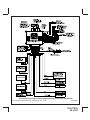
1
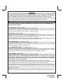
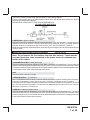
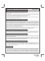
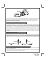
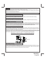
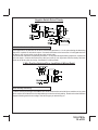
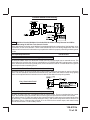
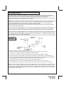
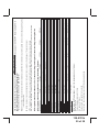
Model APS-687C
Installation Manual
Vehicle Security System
with Remote Start
Table Of Contents:
Before You Begin
Wire Harnesses Quick View
Installation Of The Major Components
6 Pin Power Harness Wiring
4 Pin Alternate Ignition Harness Wiring
12 Pin Accessory Input/Output Harness Wiring
5 Pin Aux Channel Output Harness
Door Lock Harness Wiring
3 Pin Input/Output Harness Wiring
4 Pin Auxiliary Output Harness Wiring
2 Pin Transponder Harness Wiring
Telematic Port Information
5 Pin Antenna Harness
DBI Port Information
Time Start Program
Diesel Engine Settings
Tach Rate Setting
Engine Monitoring Selections, (Voltage Tach, DBI, Hybrid,)
Diagnostics Access & Information
Multi Coil Pack Adaptor Optional
Testing Your Installation Hood Pin Safety
Manual Override Safety Testing and Operation
Neutral Safety Switch Testing
Completing Your Installation
Programming Transmitters
Programming Alarm Feature Bank 2
Programming Remote Start Feature Bank 3
Circuit Wiring Layout
Page 2
Page 3 - 4
Page 5
Page 6
Page 7
Page 8 -11
Page 11 - 12
Page 13 -15
Page 15
Page 16
Page 16 -17
Page 17
Page 17
Page 17
Page 17-18
Page 18
Page 19 -27
Page 18 -19
Page 19
Page 19 - 20
Page 20
Page 20 - 21
Page 21 - 23
Page 23
Page 24
Page 24 - 25
Page 26 - 27
Page 28
PATENTED: www.voxxintl.com/company/patents
1
Rev B: New Format Add Timing PASD & Light Blue + DBI Lock, Lock, Lock 5/2013
If booklet format, pages 26-30, Programming & Wiring Diagram shall be foldout or seperate 5 sheets
front & back.
128-8783b
1 of 28
Before You Begin
PROFESSIONAL INSTALLATION IS
STRONGLY RECOMMENDED
Roll down window to avoid locking the keys in the vehicle during
installation.
Avoid mounting components or routing wires near hot surfaces or
near moving parts like the steering wheel as it may prevent proper
operation of the vehicle.
Tape or loom wires under the hood and dash for protection as well
appearance.
Use grommets when routing wiresthrough metal surfaces to prevent
chafing and shorting.
Use a Digital Multi Meter for testing and verifying circuits. DO NOT
USE A "TEST LIGHT" OR "COMPUTER SAFE PROBE" as these
can set off air bags or damage sensitive vehicle computers and
electronics.
For technical support go to www.prestigecarsecurity.com
or call 1 800 225 6074
This device complies with FCC Rules Part 15 Operation is subject to the following two conditions
(1) This device may not cause harmful interference and
(2) This device must accept any interference that may be received, including interference that may cause
undesired operation.
NOTE:The manufacturer is not responsible for any radio or TV interference caused by unauthorized modifications to this equipment. Such modifications could void the user’s authority to operate the equipment
2
128-8783b
2 of 28
12 Pin Main Wiring Harness #1123751
1
2
3
4
5
6
7
8
9
10
11
12
Yellow/Black
Green/Orange
(+) Output To Control Factory Alarm
Tachometer Input
Black
Chassis Ground
Gray/Black
Light Blue
Negative Inhibit Shutdown Input (-)
Ground Output While Running (-) 300mA
Green/Yellow
Grey
Diesel Wait To Start Input
Shutdown Input (-)
No Connection
Brown
Positive Inhibit Shutdown Input (+)
Brown/Black
White
White
Brake Shutdown Input (+)
Parking Light Output
Parking Light Input
5 Pin Aux Channel Output Harness #1123762
1
2
3
4
5
Dark Blue
Green/Black
Channel 3 Output (-) 300mA
Channel 4 Output (-) 300mA
Light Blue/Green
Light Blue/Black
Blue/Red
Channel 5 Output (-) 300mA
Channel 6 Output (-) 300mA
Channel 7 Output (-) 300mA
3 Pin Accessory Output Harness #1123310
1
2
3
Green/White
Blue/Black
Dome Illumination Output (-) 300mA
Ex ternal Activation Triogger Input
Black/White
Horn Output (-) 300mA
5 Pin Antenna Harness
Part # 1123905
3
128-8783b
3 of 28
6 Pin Power / Start Harness #1123742
1
2
3
4
5
6
Purple
Blue
Red
Red/White
Yellow
Green
Accessory (+)
Ignition 1 (+)
Battery 2 - 12V (+)
Battery 1 - 12V (+)
Starter Output
Ignition 2 (+)
4 Pin 3rd Ignition / Start Harness #1123743
1
2
3
4
Orange/Black
N/C
Red/Black
Pink
Parking Brake Input (-)
N/C
Ignition 3 Input
Ignition 3 Output
4 Pin Alternate Output Harness #1122585
1
2
3
4
Black/Blue
Black/Green
Black/Red
Black/Yellow
Factory Disarm / Pulse Beffore Start (-)
Factory Arm / Pulse After Start (-)
Pulse After Shutdown (-)
Pulse During Crank (-)
3 Pin Door Lock Output Harness #1122906
1
2
3
Red
Green
Red/Black
(-) Lock / (+) Unlock
(+) Lock / (-) Unlock
(-) 2nd Unlock
2 Pin Transponder Output Harness #1123292
1
2
Red
Black
Battery (+) 100mA
(-) Output While Running 100mA
4
128-8783b
4 of 28
This Remote Start/Alarm System is designed to be used with Automatic Transmission- Fuel Injection
Gas or Diesel Vehicles Only!
INSTALLATION OF THE MAJOR COMPONENTS:
CONTROL MODULE:
PART # 1365034
Select a mounting location inside the passenger compartment (up behind the dashboard). The mounting
location selected must be within 24" of the ignition switch wiring harness to allow connection of the 6 pin
main wiring harness. Be certain that the chosen location will not interfere with proper operation of the
vehicle. Avoid mounting the module to or routing the wiring around the steering shaft/column, as the
module or wiring may wrap around or block the steering wheel preventing proper control of the vehicle. The
module will be secured after all wiring is completed which will allow complete access until the job is done.
Do Not Mount The Module In The Engine Compartment, as it is not waterproof.
HOOD PIN SWITCH:
PART # 1363699
The pin switche included in this package is intended for protecting the hood area of the vehicle. In all
cases, the switch must be mounted to a grounded metal surface. When the pin switch is activated, (hood
open), it will supply a ground to the input wire activating the alarm. In addition, the hood switch is required
for the safety shut down of the remote start unit. If the vehicle is being worked on, this hood switch
prevents the remote start activation even if the RF command to start is issued. This switch must be
installed in all applications. Failure to do so may result in personal injury or property damage.
THE PUSH-BUTTONPROGRAM SWITCH/LED/RECEIVER/ANTENNA ASSEMBLY: PART #1181202
The Superheterodyne Receiver Antenna Assembly provided with this unit allows routing from below the
dash board for maximum operating range. Choose a location above the belt line (dashboard) of the vehicle
for best reception. Special considerations must be made for windshield glass as some newer vehicles
utilize a metallic shielded window glass that will inhibit or restrict RF reception. In these vehicles, route
the antenna toward a rear window location for best reception. Secure the antenna with double stick tape
provided.
WARNING!! This unit is to be used in vehicles with AUTOMATIC TRANSMISSIONS only! Although this
combination Alarm/Remote Start unit is a sophisticated system with many advanced features, IT MUST
NOT be installed into a vehicle with a manually operated transmission. Doing so may result in serious
personal injury and property damage.
5
128-8783b
5 of 28
IMPORTANT!
DO NOT PLUG THE SIX PIN MAIN POWER HARNESS OR THE MULTI PIN INPUT / OUTPUT HARNESS
INTO THE CONTROL MODULE UNTIL ALL CONNECTIONS TO THE VEHICLE HAVE BEEN MADE.
AFTER SELECTING YOUR TARGET WIRES AS DEFINED BELOW, DISCONNECT THE NEGATIVE
BATTERY CABLE FROM THE VEHICLE BATTERY PRIOR TO MAKING ANY CONNECTIONS.
Note: Do not remove the fuse holders from this wire harness. Fuses must be used and located
as close as possible to the power source for adequate protection of the vehicle.
WIRING THE 6 PIN MAIN POWER HARNESS:
PART # 1123742
Note: Do not remove the fuse holders from this wire harness. Fuses must be
used and located as close as possible to the power source for adequate protection of the vehicle.
1 VIOLET Wire: Accessory Output
Connect this wire to the Accessory wire from the ignition switch. This wire will show + 12 volts when the
ignition switch is turned to the "ACCESSORY" or "ON" and "RUN" positions, and will show 0 volts when
the key is turned to the "OFF" and "START" or "CRANK" positions.
2 BLUE Wire: Ignition 1 Output
Connect this wire to the ignition 1 wire from the ignition switch. This wire will show +12 volts when the
ignition key is turned to the "ON" or "RUN" and the "START" or CRANK" positions, and will have 0 volts
when the key is turned to the "OFF" and "ACCESSORY" positions.
For Diesel Applications, this wire must be connected to the ignition circuit that powers the glow plugs if the
vehicle requires glow plug pre-heating. (See selectable feature Bank 3 #11)
3 Fused RED WIRE: + 12 Volt Battery 2 Source
Locate the vehicle battery wire(s) at the ignition switch. Verification: These wires will register voltage in all
positions of the ignition switch. Connect the Red wire to the vehicle's battery wire. This wire provides
power for the start relay and the accessory relay.
4 Fused RED/WHITE WIRE: + 12 volt Battery 1 Source
Locate the vehicle battery wire(s) at the ignition switch. Verification: These wires will register voltage in all
positions of the ignition switch. Connect the Red w/White wire to the vehicle's battery wire. This wire
provides power for the control circuit as well as the ignition 1 and ignition 2 relays.
5 YELLOW Wire: Starter Output
Careful consideration for the connection of this wire must be made to prevent the vehicle from
starting while in gear. Understanding the difference between a mechanical and an electrical
Neutral Start Switch will allow you to properly identify the circuit and select the correct installation method. In addition you will realize why the connection of the safety wire is required for
all mechanical switch configurations.
Failure to make this connection properly can result in personal injury and property damage.
In all installations it is the responsibility of the installing technician to test the remote start unit and ensure
that the vehicle cannot start via RF control in any gear selection other than park or neutral.
In both mechanical and electrical neutral start switch configurations, the connection of the Yellow wire will
be made to the low current start solenoid wire of the ignition switch harness. This wire will have +12 volts
when the ignition switch is turned to the start (crank) position only. This wire will have 0 volts in all other
ignition switch positions.
NOTE: This wire must be connected to the vehicle side of the starter cut relay (when used). For the
electrical neutral switch configuration, this connection must be made between the starter inhibit relay,
6
128-8783b
6 of 28
( when used ) and the neutral safety switch as shown in the following diagram.
Failure to connect this wire to the ignition switch side of the of the neutral safety switch can result in
personal injury and property damage.
SEE NEUTRAL START SAFETY TEST FOR FURTHER DETAILS.
YELLOW START WIRE DETAIL
6 GREEN Wire: Ignition 2 Output
Connect this wire to the ignition 2 wire from the ignition switch. This wire will show + 12 volts when the
ignition key is turned to the "ON" or "RUN" position and is some cases the "START" or CRANK" position.
This wire will show 0 volts when the key is turned to the "OFF" and "ACCESSORY" positions.
NOTE: See programming information (Bank 3 Selection #2) concerning this wire to allow output during the
"START" mode.
WIRING THE 4 PIN ALTERNATE IGNITION HARNESS
PART # 1123743
Note: Do not remove the fuse holders from this wire harness. Fuses must be
used and located as close as possible to the power source for adequate protection of the vehicle.
1 ORANGE/BLACK Wire: Parking Brake Input
This wire is used only when the turbo timer mode, Bank 3, feature # 16 is selected ON. This input insures
that the vehicle parking brake is applied whenever the vehicle is set up for and the turbo timer circuit is used.
This input must switch to ground when the vehicle's parking brake is applied. Connect the Orange/Black wire
to the negative output of the vehicle's parking brake switch.
2 N/C
This cavity of the connector is empty
3 RED/BLACK Wire: + 12 Volts Input
Note: The Red/Black and Pink are dry contacts and may be used for negative switching when necessary.
Connecting the Red/Black to chassis ground will result in Pink being ground when the R/S is activated.
This input is to be connected to a separate, (Other than the wire Red or Red/White is connected to), constant
on + 12 volt source which will supply + 12 volt power to the additional ignition output, (Pink), wire. Connect
this wire to a separate + 12 Volt source.
4 PINK Wire: Additional Ignition Output
This wire can be used as an additional + 12 Volt ignition output supplied by the Red/Black wire. This output
can be selected to be on or off during the start cycle. (See feature bank 3 selection # 8) Connect this wire
to the third ignition circuit in the vehicle and set the selectable feature # 8 of Bank 3 according to the way
in which the vehicle's ignition switch operates.
7
128-8783b
7 of 28
WIRING CONNECTIONS: 12 Pin Accessory Input/Output Harness
PART # 1123751
1 Yellow/Black Wire: + 12 Volt Alarm By - Pass Output
Note: You must disconnect the ignition input of the alarm from any other wire that it is presently connected
to in the vehicle.
This wire provides a + 12 Volt output when the ignition key is turned to the “ON” position, and 0 Volts when the ignition
key is “OFF” or when the vehicle is running under the control of the remote starter.
This wire should be connected to the ignition input of the alarm system.
This output will allow you to remote start the vehicle while leaving the alarm armed, and to lock/unlock the doors
while running under control of the remote start unit.
2 Green w/ Orange Wire: Tachometer Input Signal
This wire will continually monitor the engine's tach rate while the unit is under power of the Remote Start
module. This wire will be routed to the vehicle ECM tach input or through the firewall into the engine
compartment and connect to the negative side of the ignition coil. This Remote Start unit learns the tach
rate of the vehicle and in most cases will operate properly from one multi coil pack regardless of the
number of cylinders. If the vehicle has a single coil unit for each cylinder, it may be necessary to connect
this wire to more than one cylinder for proper tach reference. See Multi Coil Pack Adaptor wiring detail
shown later in this manual for additional information.
Note: For Hybrid mode selection, Bank 3 feature selection 5, this connection is not required, the unit will
start the vehicle and run the allotted time based on feature selection and crank duration.
3 Black Wire: Chassis Ground Source
Connect the Black wire to a known vehicle ground source or to a solid clean metal part of the chassis. Be
certain to remove any paint or grease and secure this wire with a self tapping screw and ring terminal.
4 Gray w/ Black Wire: Negative Inhibit Input 2
Any time the gray w/ black tracer wire is grounded, the Remote Starter will stop operating, even if the signal
is received from the transmitter.
If the brake light switch in the vehicle switches ground to the brake light circuit, connect the Gray w/ Black
trace wire to the output of the brake light switch. If the brake light switch in the vehicle switches +12 Volts,
do not use the Gray w/ Black wire; see Brown w/ Black tracer wire.
5 Light Blue Wire: Ignition 3 / Ground While Running Output
This wire provides a 300mA ground output that becomes active 3 seconds before the Remote Start Unit initializes, and remains grounded while running plus an additional 2 seconds after the Remote Start Ignition 1 turns
off. In all of the applications described below, a relay will be required. The Light Blue wire can be used to
accommodate the following situations:
A. Sensor By Pass:
If there is a Non Plug in Sensor used with the alarm system and it is not shunted during the Remote
Start activation period, then vibration or noise from the running vehicle can cause the alarm to trigger. In
this case, connect the Light Blue Wire to terminal #86 of a external relay. Connect terminal # 85 of the
relay to a fused + 12 volt battery source. Cut the sensor's trigger wire and connect one end of the cut
wire to terminal #30 and the other end of the cut wire to terminal #87a. Just before the Remote Start
8
128-8783b
8 of 28
unit is activated, the relay contacts will open, preventing the sensor's operation until the Remote Start
unit shuts off.
B. Additional Ignition Output:
Some vehicle's may require more than three ignition outputs to start and keep the vehicle's engine
running. If this is the case, connect the Light Blue wire to terminal #86 of an external relay. Connect
terminal # 85 to a fused + 12 volt source. Dependent on the vehicle's requirement, connect terminal #30,
to a fused + 12 volt source, or to ground, and connect terminal 87 to the vehicle to supply the additional
ignition source.
C. GM VATS Key Override:
If the vehicle has the General Motors VATS system installed, you will need to bypass the system while
the vehicle is operating under the control of the Remote Start Unit. To Do This:
1. Measure the resistance of the resistor pellet on the ignition key then select a resistor within 5% of the
key's value from the resistor pack supplied.
2. Locate the pair of VATS wires in the vehicle, usually a pair of thin gauge wires running from the
ignition switch to the VATS control module.
NOTE: These wires are typically White w/ Black trace and Violet w/ Yellow trace, however in later model
Cadillacs, they are run through an orange sleeve, and are either both Black, both Yellow, or both White
wires. Consult the factory service manual for additional information.
3. Connect the Light Blue Wire from the Remote Start Unit to terminal #86 of an external relay.
Connect terminal #85 of the relay to a fused + 12 volt battery source.
4. Cut (#1) wire (as shown), and connect the ignition switch side of the cut wire to terminal #87a of the
relay. Connect the other side of the (#1) wire to terminal #30.
5. Connect the previously selected resistor from terminal #87 to the second (#2) wire (as shown).
NOTE: The above information and following diagram is for the GM VATS system only.
D. Anti-Grind Starter Circuit Connection:
This wire, when connected to a starter inhibit relay, as shown in the diagram below, will prevent the
customer from engaging the starter while the vehicle is running under control of the remote start.
9
128-8783b
9 of 28
Configured in this way, while the remote start is controlling the vehicle, the light blue wire has ground on it
all the time. This ground will cause the relay to energize preventing current flow through the normally
closed contacts. This will prevent a customer who inadvertently turns the ignition switch to the start
position, from sending current to the starter.
6 Green/Yellow Wire: Diesel Wait To Start Input
The Green/Yellow wire of the 12 pin connector will connect to a diesel vehicles glow plu wire. When the unit receives
a start command, this wire must go to + 12 then to ground to allow the crank sequence to begin. When ignition #1
is activated by the remote start unit, the glow plug circuit gets energized, (+ 12 volts), when the glow plug circuit of
the vehicle drops the + 12 volts, which effectively grounds the wait to start input, then 500mS later the starter will
engage. This wire can also be connected to the Glow Plug Bulb wire in the vehicle if this bulb wire gets + 12 volts
when the ignition comes on and drops low when the glow plug circuits temperature is reached. Be sure to fuse the
wire with a 1 Amp Fuse when connecting to a high current circuit such as a factory glow plug wire. The fuse should
be installed as close to the high current wire as possible. If you are installing this unit in a Gasoline vehicle, this wire
is not used.
7 Gray Wire: Negative Inhibit Input 1
Connect the GRAY wire to the previously mounted hood pin switch provided. This wire will be routed through
the firewall into the engine compartment. It is necessary to use an existing grommet when passing wires
through the firewall to prevent short circuiting. This is an important safety feature of the System, failure to use
this feature can result in serious injury. Route the wire to the pin switch and connect it using a spade connector
8 Brown Wire: Positive Inhibit Input 1
Any time + 12 Volts is applied to the Brown wire, the Remote Starter will stop operating, even if the signal
is received from the transmitter.
If the vehicle has a factory installed hood pin switch and that switch provides + 12 Volts to an under hood light,
the Brown wire can be connected to the existing pin switch.
10
128-8783b
10 of 28
9 Brown w/ Black Wire: Positive Inhibit Input Plus Trigger When Armed
The Brown w/ Black Trace wire provides an instant shutdown for the Remote Start Control module whenever
it gets + 12 volts also triggers the alarm when armed. If the Brake lights switch in the vehicle switches + 12
volts to the brake light circuit, connect the Brown w/ Black trace wire to the output side of the brake switch.
This will allow the Remote Start to shut down if an attempt is made to operate the vehicle without the key
while running under the control of the Remote Start. In most vehicles, in order to shift into gear, the brake
pedal must be depressed. The brake input will in turn cause the remote start unit to shut off.
10 No Connection
11 White Wire: Parking Light Flasher Output
This wire is the normally open contact of the on board parking light flash relay. Connect this wire to the
vehicle's parking light feed wire. This is the wire that gets switched on, either (+) or (-), when the vehicle's
parking light switch is activated.
12 White Wire: Parking Light Flasher Input
This wire is the common contact of the on board parking light flasher relay. If the vehicle you are working on
has +12 volt switched parking lights, connect this wire to a fused + 12 volt source. (Max. 15 Amps)
NOTE: If the vehicle's parking lights are ground switched, connect this wire to chassis ground.
Parking Light Wiring Detail
5 Pin Aux Channel Output Harness
Part # 1123762
1 Dark Blue Wire : Delayed 300 mA Pulsed Output/Channel 3
The dark blue wire pulses to ground via an independent RF channel from the keychain transmitter. This is
a transistorized, low current output, and should only be used to drive an external relay coil.
This output is activated by the same transmitter button that is used to activate the remote start function. Press
11
128-8783b
11 of 28
and hold the trunk/key button to activate this trunk release output, or press and release the trunk/key button
two times within 2 seconds to activate the remote starter.
WARNING: Connecting the dark blue wire to the high current switched output of the trunk release
circuits and some remote start trigger inputs, will damage the control module.
Connect the dark blue wire to terminal 86 of a 30 A automotive grade relay, connect terminal 85 to a fused
+12 volt source and wire the remaining relay contacts to perform the selected function desired.
2 Green w/ Black Trace Wire: 300 mA Latched Channel 4 Output
The Green w/ Black Trace wire supplies a 300 mA switched output whenever channel four of the receiver is
accessed. Pressing the pre-programmed transmitter button(s) will access channel four and will remain
active, for up to 20 seconds, as long as the transmitter button(s) is held.
This is a low current output and must be connected to a relay to supply power to the device you intend to
control.
Note:
This wire also can be used for defrost activation as dictated by the setting of feature # 1 of Bank 3.
Anytime the vehicle is running under control of the Remote Start and Channel 4 is activated, then
dependent on the selection of this feature, Green/Black will be activated as a pulse for 1 second, or
for 10 minutes. Note this wire will not operate when the vehicle is running under the power of the
ignition key, only while under the control of the remote start or if not used for defrost then an output
will occur as indicated above.
WARNING: Connecting the green/black to a high current circuits, will damage the control module.
Connect the green/black to terminal 86 of a 30 A automotive relay.
Connect terminal #85 of the relay to a fused + 12 volt source, and wire the remaining relay contacts to
perform the selected function of channel 4.
3 Lt Blue/Green Wire : Delayed 300 mA PULSED OUTPUT / CHANNEL 5
The light blue/green wire pulses to ground via an independent RF channel from the keychain transmitter. This
is a transistorized, low current output, and should only be used to drive an external relay coil.
WARNING: Connecting the light blue/green to a high current circuits, will damage the control module.
Connect the green/black to terminal 86 of a 30 A automotive relay.
Connect terminal #85 of the relay to a fused + 12 volt source, and wire the remaining relay contacts to
perform the selected function of channel 5.
4 Lt Blue/Black Wire : (-) 300mA Selectable Output Channel 6
The light blue/black wire pulses to ground via an independent RF channel from the keychain transmitter. This
is a transistorized, low current output, and should only be used to drive an external relay coil.
WARNING: Connecting the light blue/black to the high current circuits, will damage the control module.
Connect the light blue/black to terminal 86 of a 30 A automotive relay.
Connect terminal #85 of the relay to a fused + 12 volt source, and wire the remaining relay contacts to
perform the selected function of channel 6.
5 Blue/Red Wire : Delayed 300 mA PULSED OUTPUT / CHANNEL 7
The blue/red wire pulses to ground via an independent RF channel from the keychain transmitter. This is a
transistorized, low current output, and should only be used to drive an external relay coil.
12
128-8783b
12 of 28
WARNING: Connecting the light blue/red to the high current circuits, will damage the control module.
Connect the light blue/green to terminal 86 of a 30 A automotive relay.
Connect terminal #85 of the relay to a fused + 12 volt source, and wire the remaining relay contacts to
perform the selected function of channel 7.
3 Pin Door Lock/Unlock Harness: (White Connector) 300mA
Part # 1122906
1 Red Wire: (-) Lock or (+) Unlock
The Red wire provides a (-) Negative Pulse when locking and a (+) Positive Pulse when unlocking.
2 Green: (+) Lock or (-) Unlock
The Green wire provides a (+) Positive Pulse when locking and a (-) Negative Pulse when unlocking
3 Red/Black: (-) Second Unlock
The Red w/Black trace wire will provide a pulsed ground only, and will only provide an output when the unlock
button of the transmitter is pressed a second time after a first unlock command was issued. This is used for
second step unlock or all doors unlock in a two step circuit. In this arrangement, Red is used to control the
drivers door unlock relay, and the Red/Black will be used to control unlock of all other doors.
3 Wire Ground Switched Door Lock Circuits:
In this application, the Red wire of the door lock harness provides a ground pulse during the arming sequence, or pulsed ground lock output. Connect the Red wire to the low current ground signal wire from the
factory door lock switch to the factory door lock relay.
The Green wire of the door lock harness provides a ground pulse during the disarming sequence, or pulsed
ground unlock output. Connect the Green wire to the low current ground signal wire from the factory door
unlock switch to the factory door unlock relay. See the following diagram for Wiring Detail.
3 WireGround Switched Door Lock/Unlock Wiring Detail
Driver Priority Unlocking:
For driver Priority Unlocking the Red/Black wire will be connected to unlock all doors, and the red, or green
will be used to unlock the drivers door dependent upon the door unlock polarity. Please review the reference
diagram below and wire according to the vehicle type you are working on.
13
128-8783b
13 of 28
Negative Switch Driver Priority
3 Wire Positive Switched Door Locks:
In this application, the Red wire of the door lock harness provides a + 12 volt pulse during the disarming
sequence, or pulsed 12 volt unlock output. Connect the Red wire to the low current 12 volt signal wire from
the factory door unlock switch to the factory door unlock relay.
The Green wire of the door lock harness provides a + 12 volt pulse during the arming sequence, or pulsed 12
volt lock output. Connect the Green wire to the low current 12 volt signal wire from the factory door lock
switch to the factory door lock relay. See Below For Wiring Detail.
3 Wire Positive Switched Door Lock/Unlock Wiring Detail
Driver Priority Unlocking:
For driver Priority Unlocking the Red/Black wire will be connected to unlock all doors, and the red, or green
will be used to unlock the drivers door dependent upon the door unlock polarity. Please review the reference
diagram following and wire according to the vehicle type you are working on.
14
128-8783b
14 of 28
Positive Switch Driver Priority
NOTE: Resistive Circuits, Multiplex Circuits As Well As 4 Wire Polarity Reversal and 5 Wire
Alternating 12 Volt Door Lock Control Circuits
These applications require the use of additional components which may include relays, fixed resistors, or for
convenience, a Door Lock Interface. Refer to the AUDIOVOX Door Lock Wiring Supplement and or the
Audiovox fax back service for information on your particular vehicle for properly connecting to these types of
circuits.
3 Pin Input/Output Harness:
Part # 1123310
Dark Blue/Black Trace Wire: External Trigger Input
The Dark Blue/Black trace wire allows the remote start unit to be activated from an external source. The
intent of this wire is to allow the unit to be controlled from a "POSSE/CAR-LINK" paging system or similar
device. When this wire receives a ground pulse, the unit will start the vehicle. Connect this wire to a ground
pulsed output from the controlling circuit.
Green w/ White Trace Wire: Entry Illumination Ground Output
This wire provides a 30 second ground output (300 mA Max.) whenever the remote is used to unlock the
doors. This wire should be connected to an external relay, and wired to the vehicles interior entry lighting
whenever the optional Interior Illumination circuit is desired. See below for relay wiring details.
Entry Illumination Detail
Black w/ White Trace Wire: 300 mA Horn Output
The black w/ white trace wire is provided to beep the vehicle’s horn. This is a transistorized low current
output, and should only be connected to the low current ground output from the vehicle’s horn switch.
If the vehicle uses a +12 VDC horn switch, then connect the black w/ white trace wire to terminal 86 of the
AS 9256 relay ( or an equivalent 30 Amp automotive relay ), and connect relay terminal 85 to a fused +12
VDC battery source. Connect relay terminal 87 to the vehicle’s horn switch output, and connect relay
terminal 30 to a fused +12 VDC battery source.
15
128-8783b
15 of 28
WIRING THE 4 PIN AUXILIARY OUTPUT HARNESS
Part #1122585
The auxiliary 4 pin connector provides low current outputs to control various functions in the vehicle during
different stages of the Remote Start unit's operation. Understanding these outputs and the time in which they
occur will allow you to determine if they are needed for the particular vehicle you are working on as well as
how to use them.
1 Black w Blue Trace Wire: Pulsed Ground Output Before Start
The Black w/ Blue Trace wire will provide a 1 second 300 mA pulsed ground output 1.5 second before the
remote start unit activates as well as when the transmitter is used to disarm the system. Typical use for this
output would be to disarm a factory theft deterrent system to prevent false triggering of the factory alarm
when the remote start unit engages or when the system is used to unlock the doors. This will also activate
when the transmitter is used to disarm/unlock the system
NOTE: This output can be selected to operate like the door lock output as set in alarm feature setting #1 by
selecting feature #17 in Bank 3 for 2 Chirps.
2 Black w/ Light Green Trace Wire: Pulsed Ground Output After Start
The Black w/ Light Green Trace wire will provide a 1 second 300mA pulsed ground output after the vehicle is
started under control of the remote start unit. Typically this wire will be used to re-lock the vehicle doors if the
doors unlock automatically when the factory anti-theft system is disarmed. This wire will also activate when
the transmitter is used to arm/lock the system.
3 Black w/ Red Trace Wire: Pulsed Ground Output After Shutdown
The Black w/ Red Trace wire will provide a 1 second 300 mA pulsed ground output after the remote start unit
shuts down. This output will occur regardless of whether the circuit times out or is manually terminated.
Typically this output will be used to re-lock the vehicle doors if the doors unlock automatically when the
ignition circuit transitions to off.
4 Black w/ Yellow Trace Wire: Ground Output During Start (Crank)
The Black w/ Yellow Trace wire will provide a 300 mA ground output while the starter output of the remote
start unit is active. This output can be used to activate the Crank Low/Bulb Test wire found in some GM
vehicles. This wire is also referred to as the ECM wake up wire in some vehicles.
NOTE: The outputs above are low current outputs and must be used with a relay if the circuit's requirement
is more than 300 mA.
2 Pin Transponder Control Output: (Yellow Connector)
Part # 1122392
a: When selected for while remote start on, the Black wire will be active at the same time ign. 3 becomes
active, and will remain active all the time the unit is operational under the control of the remote start.
b: When selected for output during the start sequence, the Black wire will be active at the same time Ign.
3 becomes active, and will remain active until the vehicle has started. This will be used for one time read
transponder circuits.
c: When the unit is selected for until ignition off, the Black wire will become active at the same time ign. 3
becomes active and will remain active even after the key take over and until the ignition in the vehicle is
turned off. This will allow the unit to be used for continuous read transponders circuits.
16
128-8783b
16 of 28
1 Black: 250mA Output (-)
The black wire switches on when the remote start is activated and will stay on as programmed in the
remote start feature Bank3 Feature 12.
2 Red: 250mA Output (+) 12 Volts Constant
This output is intended to allow the control of a transponder bypass interface module or transponder
bypass relay.
Additional Harnesses And Connectors For The System
4 Pin Upgrade Telematic Module:
Connector Port)
Red = + 5 Volts / Black = Ground / White = Data TX / Yellow = Data RX
Connect the 4 pin harness found in the Telematic one way or CArlink II kits to the mating port on the
controlling circuit.
NOTE: If using the TWO WAY Telematic module, only Ground, TX, and RX are used on this port, the + 12
volt supply for the two way module must be sourced separately or the unit will not operate.
5 Wire Antenna/Receiver Program Push-Button Switch/LED Connector:
Part # 1123906
Plug the previously routed antenna connector from the antenna receiver assemble into the mating connector
of the control module. This connector supplies 12 volts, ground and RF data input and output, LED cathode,
and Valet Enable to and from the antenna receiver and the remote start module. Be certain this connector
is firmly seated making good contact to the control unit.
4 PIN IN VEHICLE DATA BUS PORT (DBI Port)
(Connector Port)
The 4 pin port located on the side of this module is for proprietary Audiovox data bus interface modules.
These modules are used to access a variety of features in the vehicle which can be as simple as door trigger
inputs, to more complex door locks outputs, or transponder interfaces for remote starting. DO NOT connect
anything to this port other than the Audiovox IDB modules or damage to the Remote Start module will occur.
All installation instructions for the IDB modules will be packaged with the individual component along with
the proper 4 pin wiring harness requires to access the data transmit & receive as well as the proper voltage
levels for the interface.
TIMED START PROGRAM:
The Remote Start unit has the ability to start the vehicle automatically at timed intervals. This feature is
useful in extremely cold climates where starting the engine is the only means to keep the battery charged
and fluids warm. The operator has the option to have the unit start every 2 or 4 hours for a maximum of 48
hours. Factory preset is to start at 4 hour intervals. To select 2 or 4 hour automatic start timer:
1. Start By Holding the Push Button Switch found on the windshield mount receiver on.
2. While Holding the Push Button Switch Turn The Ignition Switch On Then Off
3a) Within 10 seconds of turning the ignition switch off, Release and then Push On and release the Push
Button Switch 2 times holding it on the second time until the siren and or lights flash and chirp 2 times
indicating that the 2 Hour Start Interval has successfully been set.
or
17
128-8783b
17 of 28
3b) Within 10 seconds of turning the ignition switch off, (Step 2) Release
and then Push On and release the Push Button Switch 4 times holding it on the fourth time until the siren
and or lights flash and chirp 4 times indicating that the 4 Hour Start Interval has successfully been set.
NOTE: Once selected, 2 or 4, this timer interval will remain in memory until it is manually changed. To
change, the above sequence will have to be followed.
TIMED START OPERATION:
To begin the start timer, within 10 seconds of turning off the ignition switch, activate the RF command to start
2 times. (Press the start button four times). The lights will flash and the siren will chirp 4 times. Indicating
timed interval mode has been initiated. The vehicle will automatically start every 2 or 4 hours as programmed.
To cancel the timed start mode start the vehicle either by RF or by the ignition key.
DIESEL ENGINE SETTINGS:
NOTE: When selecting Diesel operation, (Bank 3 Feature #11), over gasoline, the only change is to the
ignition circuits. When Diesel is selected, the ignition circuits will power up 10, 15, or 20 seconds before
the start circuit. The intent of this feature is to allow the glow plug warming required by some diesel
engines. If your vehicle is a instant start diesel, it is not necessary to activate this feature.
ALSO: When selecting Diesel mode, be certain that the intended vehicle has a true tach reference and be
certain to connect the tach input wire. Also note, if the "Diesel Wait to Start" input is connected,
(Green/Yellow) this wire will take precedence over the Diesel selection of bank 3 feature 11.
Monitoring The Vehicle's Engine:
(Program Feature #5 Bank 3)
There are 4 ways that the remote start monitors the engine running, one or the other must be selected for
your application for the remote start to operate correctly.
1) VOLTAGE SENSE SETTING:
The unit will monitor the voltage level of the battery during remote start, wait for the voltage to drop while
cranking, then look for the voltage level to go above the level it was before the vehicle began to crank which
indicates the vehicle is running. Feature #14 of Bank 3 must be set for preset time or the voltage sense
feature will not operate indicated by the parking lights flashing 7 times.
2) TACH RATE SETTING:
1. Turn the ignition key to the On position.
2. Press and release the valet/program push button switch 3 times.
3. Immediately turn the ignition key Off.
4. Press and hold the valet/program push button switch, then start the vehicle using the key.
5. When the unit senses the tach signal, the parking lights will begin to flash.
6. Release the valet/program pushbutton switch. The parking lights will turn on for three seconds to indicate
that the learned tach signal is stored and the unit is out of the tach learn mode.
NOTE: If the unit fails to learn tach rate due to an improper tachometer connection or a poor tach source, the
parking lights will not flash. To correct this situation, locate and connect the Green/Orange wire to
the proper tach signal, and then repeat the tach learn routine.
18
128-8783b
18 of 28
3) DBI TACH SETTING
Selecting this setting in the option menu indicates that you have a DBI module and have determined that a
tach signal is available for the vehicle you are connecting to. The unit will look at the DBI data port for the
tach signal. If the vehicle fails to start, or the unit flashes 7 times, recheck the DBI manual to insure that
tach is available for your vehicle. If not the tach connection wire, Green/Orange must be used.
4) HYBRID SETTING:
Selecting this setting in the option menu allows for Hybrid vehicles. Also feature #14 of Bank 3 must be set
for preset time or the Hybrid feature will not operate indicated by the parking lights flashing 7 times.
CRANK AVERAGING:
When Feature 14 Bank 3 is set for crank averaging, the remote start unit constantly monitors and learns the
cranking patterns of the vehicle each time the car is started with the key. The vehicle must be started
atleast 4 times with the key for the crank averaging circuit to begin it's monitoring the vehicle's engine.
DIAGNOSTICS:
Enter Bank 3 and turn on selectable feature # 9 as described on the front pages of this manual.
NOTE: Diagnostic mode is a temporary mode. Once you have accessed the diagnostic mode, the unit will
pause for two seconds then begin to flash the last stored shut down code. This code will be displayed three
times in succession, then the unit will automatically exit the diagnostic on mode.
The parking lights will flash a number of times indicating the reason for the last remote start shutdown. The
light flash indications are as follows:
1
2
3
4
5
6
7
8
Flash
Flashes
Flashes
Flashes
Flashes
Flashes
Flashes
Flashes
Run timer expired
Low or no tach signal (RPM)
Positive inhibit wire activation
NA
RF shutdown, Remote signal received, or manual start trigger wire reactivated.
High tach signal (RPM)
Tach signal has not been learned
Negative inhibit wire
Multi Coil Pack Adaptor: (Optional)
The multi coil pack adapter, is designed for use with vehicles that do not respond to single coil tach
programming. Although the tach resolution of this circuit is designed to interface direct with most vehicles,
there may be an occasion where the following circuit may be required. Construct the adaptor as shown
below.
To use the adaptor, the Green/Black wires must connect to the negative side of the ignition coil(s).
1. For vehicles utilizing independent coils per cylinder, connect the three Green/Black leads to alternate
coils. To achieve optimum performance the coil signals must be evenly distributed. This is accomplished
by first mapping out the firing order of the engine in groups of as indicated below. Draw a circle around
any of the columns. The Green/Black wires should be connected to the negative (-) terminal of the
respective cylinder number which appears in any of the circles.
2. For vehicles utilizing 2 cylinder firing per coil pack, connect Green/Black to the tach side of each coil
pack. For 8 cylinder, four coil systems, connect to any of the three coils.
3. Connect the Yellow wire to a +12 volt ignition 1 source. This wire will have +12 volts with the ignition in
the on and start position and have 0 volts with the ignition in the off position.
4. Connect the Green wire to the (Green) or (Orange/Green) tach input of the Audiovox remote start unit.
19
128-8783b
19 of 28
TESTING YOUR INSTALLATION:
WARNING!! The following procedure must be performed after the installation of any Remote Start Device. It is the
responsibility of the installing technician to complete these tests. Failure to test the unit in the following manner
may result in personal injury, property damage, or both.
HOOD PIN SAFETY SHUT DOWN:
The intent of the hood pin safety shut down is to prevent the Remote Start unit from being activated while a
mechanic or vehicle owner is performing normal routine vehicle maintenance.
To test the integrity of this circuit:
1. With the drivers window in the down position, start the vehicle using the RF transmitter.
2. Reach inside the car and pull the hood release.
3. Raise the hood and confirm that the remote start unit shuts down.
If the unit fails this test, recheck your pin switch connection to the Gray/Black wire of the Remote Start Unit.
DO NOT RELEASE THIS VEHICLE TO THE CONSUMER UNTIL YOU CONFIRM THE
OPERATION OF THE HOOD PIN SAFETY SHUT DOWN FEATURE.
REMOTE START OVERRIDE MODE / MANUAL SHUT DOWN:
The intent of the remote start override / manual shut down circuit is to allow the vehicle operator to prevent
operation of the Remote Start Unit regardless of the RF transmitter operation.
To Enter The Remote Start Override Mode:
1) With the system disarmed/unlocked, and the ignition switch off Press and Hold the pushbutton switch
located on the receiver unit on.
2) Turn the ignition switch on, off, on, off, on, off.
3) The LED begins to flash two short flashes followed by one long flashes and continues this pattern until
returned to normal mode of operation.
The action above puts the unit into the Remote Start Override mode or vehicle service mode and will not start
from the RF transmitter or any other input.
To Exit Remote Start Override Mode:
1) With the system disarmed, press and hold the PBLED on.
2) Turn the ignition switch on, off, on, off, on, off.
3) The LED turns off indicating that the R/S unit is fully functional one again.
20
128-8783b
20 of 28
DO NOT RELEASE THIS VEHICLE TO THE CONSUMER UNTIL YOU CONFIRM THE
OPERATION OF THE MANUAL SHUT DOWN / ENABLE FEATURE.
NEUTRAL START SAFETY TEST:
The intent of the neutral start switch is to prevent the vehicle from starting while the gear selector is in any position
other than Park, or Neutral. When installing a Remote Start Device, it is imperative that theYellow Starter wire be
connected to the ignition switch side of the Neutral Start Switch. Consideration for the placement of a starter inhibit
relay is important as well and should be connected to the ignition switch side of the Yellow Start Wire.
To test the integrity of the Neutral Start Safety Circuit:
1) Set the vehicle parking brake.
2) Block the drive wheels to prevent vehicle movement.
3) Temporarily disconnect the Brown/Black positive shut down wire from the vehicle's brake switch.
4) Sitting in the vehicle, start the engine using the vehicle's ignition key.
5) Step on the brake pedal and shift the gear selector into reverse.
6) Allow the transmission to shift. When you feel the engine pull, do not move the gear selector just turn the
ignition switch off. DO NOT attempt to remove the key.
7) Keeping the brake pedal depressed, activate the RF transmitter in an attempt to start the vehicle. The car
should not start.
8) Repeat the above test this time move the gear selector to the drive position.
If the unit attempts to start, failing this test, recheck your Yellow Wire's connection. This wire must be connected
to the ignition switch side of the Neutral Start Switch. If the vehicle you are working on does not have an
Electrical Neutral Safety Switch, it will be necessary to reconfigure the Remote Starts Wiring to accommodate
the vehicle. The information concerning the Mechanical Neutral Safety Switch provided below will help you to
determine if the vehicle you are working on has this type of safety switch and will provide alternate wiring
methods to accommodate this situation.
CAUTION! REMEMBER TO RECONNECT THE BROWN/BLACK NEUTRAL SAFETY WIRE
TEMPORARILY DISCONNECTED IN STEP 3
MECHANICAL NEUTRAL SAFETY SWITCH CONSIDERATIONS:
Mechanical neutral safety switch configurations differ slightly in that they do not offer the same level of safety
when installing a remote start device. Often when the ignition switch is turned off while the gear selector is in any
position other than park or neutral, the mechanical function will not allow the key to be turned to the start position
or be removed from the ignition cylinder. This configuration prevents mechanical operation while the vehicle is in
gear but offers no consideration for electrical operation. Because of this potential problem, this installation
requires the additional connection of a safety wire from the remote start device to the vehicle Park/Neutral ECM
Input or the vehicle key in sensor. This connection will prevent remote start operation if the key is left in the ignition
switch regardless of the gear selectors position.
DO NOT RELEASE THIS VEHICLE TO THE CONSUMER UNTIL YOU CONFIRM THE OPERATION
OF THE MECHANICAL NEUTRAL SAFETY START FEATURE.
21
128-8783b
21 of 28
KEY IN SENSOR CIRCUITS:
If the vehicle you are working on does not have or you cannot locate the ECM reference wire, there are two
alternatives available. Although not preferred, the vehicle Key In Sensor may be reconfigured to allow a margin
of safety and will prevent the vehicle with a Mechanical Neutral Start Switch from starting in gear.
AUDIOVOX ADVISES THAT YOU MAINTAIN THE FACTORY CIRCUIT WHENEVER POSSIBLE. The following two
circuits may be used only if the above circuit is not available.
NOTE: When completing an installation using either of the following key in sensor circuits, if the operator inserts
the ignition key while the vehicle is running under the control of the Remote Start, the vehicle will shut down.
This must be explained to the operator as it is in contrast to the normal operation of a vehicle utilizing an
electrical neutral start switch and is inconsistent with the operators manual.
Additional information concerning Key In Sensor methods 1 and 2 are listed below and should be reviewed
before considering either alternative.
Method 1 will allow the safety required for the remote start unit and prevent the vehicle from starting while in any
gear other than Park or Neutral while the key is in the ignition cylinder however, if the key is left in the ignition
switch and the door is left opened, the added relay will be energized causing a 150mA drain on the battery.
Method 2 will allow the safety required for the remote start unit and prevent the vehicle from starting while in any
gear other than Park or Neutral while the key is in the ignition cylinder however, the original factory key in chime
module will not alert the owner that the key has been left in the ignition switch. In addition, this may also effect
other warning tones such as the light on reminder.
These situations should be carefully considered before altering the vehicle's wiring and must be fully explained
to the consumer.
METHOD 1
To connect to the key in sensor as shown in method 1:
1) Locate the control wire that connects the drivers door pin switch to the key in sensor switch.
2) Cut this wire and connect the ignition cylinder side to chassis ground.
3) Locate the key in sensor switch wire that connects the chime module to the ignition cylinder .
4) Cut this wire and connect the ignition cylinder side to terminal 30 of a P&B VF45F11 or equivalent relay.
5) Connect the cathode (striped) side of a 4002 series diode to this same wire, and connect the (non striped) side
to the negative shut down safety wire (Gray / Black) of the Audiovox Remote Start Unit.
6) Connect terminal 86 of the relay to a fused +12 volt constant battery source.
7) Connect terminal 87 of the relay to the Chime Module side of the previously cut wire in step D.
8) Connect terminal 85 of the relay to the Drivers Door side of the pin switch wire previously cut in step B.
NOTE: A second 4002 series diode may be required to maintain the integrity of the hood open, shut down circuit.
If this is the case, it must be installed as shown in the diagram above. The anode (Non Striped) side must be
connected to the Gray/Black wire of the Remote Start Unit. The cathode (Striped) side must be connected to the
hood pin switch. If the hood pin switch is also used for an alarm trigger input, be certain to use the dual diode set
up shown earlier in this manual.
22
128-8783b
22 of 28
METHOD 2:
To connect to the key in sensor circuit as shown for method 2:
1) Locate the control wire that connects the drivers door pin switch to the key in sensor switch.
2) Cut this wire and connect the ignition cylinder side to chassis ground.
3) Locate the key in sensor switch wire that connects the chime module to the ignition cylinder .
4) Cut this wire and connect the ignition cylinder side to the Remote Start Negative Safety Shut down Wire Gray/
Black, using a 4002 series diode as shown above.
NOTE: A second 4002 series diode may be required to maintain the integrity of the hood open, shut down
circuit. If this is the case, it must be installed as shown in the diagram above. The anode (Non Striped) side
must be connected to the Gray/Black wire of the Remote Start Unit. The cathode (Striped) side must be connected to the hood pin switch. IIf the hood pin switch is also used for an alarm trigger input, be certain to use
the dual diode set up shown earlier in this manual.
AFTER THE CONNECTION OF THE NEUTRAL START SAFETY WIRE AS
INDICATED IN ANY OF THE PREVIOUS ALTERNATE CONFIGURATIONS, THIS CIRCUIT
MUST BE TESTED FOR PROPER OPERATION.
Retest by following the steps outlined in the NEUTRAL START SAFETY TEST section of the manual.
COMPLETING THE INSTALLATION:
After you have confirmed the operation of the Audiovox Remote Start unit and tested all the safety features of the
system:
1) Mount the control module up and behind the dash securing it in place with cable ties or screws. Be certain that
the chosen mounting location will not inhibit any of the controls of the vehicle.
2) Securely harness and tie all wiring up and away from all hot and moving parts that they may come in contact with
under the dash board or in the engine compartment areas.
CAUTION:
Particularly avoid the area around the steering shaft and column, as wires can wrap around
these mechanisms and impair the safe operation of the vehicle.
3) Apply the Caution Labels supplied with this kit to a conspicuous area in the engine compartment. Make sure to
clean the surface before affixing the label.
4) Check the vehicle's wipers, lights, horn, etc.... to insure proper operation.
5) Replace all panels that were removed during installation, and retest the system.
6) Explain all activated features and safety systems associated with the Remote Start Unit installed. Also point out
the location of the Push-Button LED Override/Valet switch to the customer and explain it's operation.
23
128-8783b
23 of 28
The transmitters are pre-programmed from the factory, If you find you need to program new or additional
transmitters follow the instructions below.
PROGRAMMING BANK 1 (TRANSMITTERS):
1) Turn the ignition key to the on position.
2) Press and release the valet/programming switch 3 times (Siren Chirps).
3 Press the Lock Button of each transmitter you want programmed until you hear a chirp from the horn or
siren.
4) Turn the ignition switch off.
The above action programs the Lock, Unlock, Start/Trunk, and Option 1 buttons of the system. For additional channel programming see the owners guide found within the literature bag packaged with this kit.
PROGRAMMING BANK 2 (ALARM FEATURES):
You can enter bank 2 from bank 1 by turning the ignition key off then on from step 4 of Bank 1.
(Siren Short then Long Chirp), or You can also go right to bank 2 by:
1) Turn the ignition key to the on position.
2) Press and release the valet/programming switch 3 times (Siren Chirps).
3) Turn the ignition key off then on. (Siren Short Then long Chirp)
4) Press the pushbutton switch once to advance to feature 1, twice to advance to feature 2, etc,,,then use the
lock button of the transmitter to select the feature setting.
Example to set passive arming:
1) Turn the ignition key to the on position.
2) Press and release the valet/programming switch 3 times (Siren Chirps).
3) Turn the ignition key off then on. (Siren Short Then long Chirp)
4) Press the pushbutton switch six times to advance to features 6, Pass/Act Arm, then use the lock button
of the transmitter to select two chirps "Passive Arm".
5) To exit the programming mode, turn the ignition key off. The program mode is automatically exited when
there is no activity on the pushbutton switch or the transmitter lock button.
24
128-8783b
24 of 28
25
128-8783b
25 of 28
1 Chirp
1 Sec.
Auto Lock On
Auto UL Dr.
Not Available
Not Available
Not Available
Not Available
10mS
Not Available
On
On
Not Available
Not Available
Not Available
Pulse
Pulse
Pulse
Not Available
Push & Hold
Push & Hold
Push & Hold
Off
Off
16mS
2 Chirps
3.5 Sec.
Auto Lock Off
Auto UL All
10 Sec
10 Sec
10 Sec
30mS
Auto UL Off
3 Chirps
1 Sec L, Dbl. U/L
Siren chirps 2 times indicating access to RF feature program mode.
Press and hold valet switch for 5 seconds
Turn ignition off then on
When using the RF programmer, enter the program mode as follows:
Turn the ignition on
Press and release valet switch 3 times
Feature Selection
1st DoorL/UL
2nd Accy Lock
3rd Accy. UL
4th Headlights
5th Passive Locks
6th Pass/Act Arm
7th Siren/Horn
8th Horn Chirp
9th O/R Method
10th 2 Step U/L
11th Chp Del Tx
12th Volts/HdWire
13th Trigger Circuits
14th L/UL Poll
15th Aux Ch 5 Sel
16th Aux Ch 6 Sel
17th Aux Ch 7 Sel
18th Trigger Delay
RF Programmable Features Bank 2 Is Alarm Selectable Features:
20 Sec
20 Sec
20 Sec
40mS
4 Chirps
Dbl L, 1 Sec UL
Latch On/Off
Latch On/Off
Latch On/Off
50mS
5 Chirps
Dbl L, Dbl UL
Hold 3/S For O/P
Hold 3/S For O/P
Hold 3/S For O/P
6 Chirps
1 S l/350mS ul
RF Programmable Feature Bank 1 Is For Transmitter Programming See Transmitter Programming Guide.
NOTE: Keyless Entry Models with no horn output will Flash the Parking Lights instead of chirp where chirp is indicated.
Also, No data will be indicated if a feature is not available for a particular model. The unit will enter the feature but no selection will be available.
Be certain to place a check mark indicating the method used in the box located on the last page of the owner's manual.
Note : The method of manual override can either be selected to operate from the valet switch or operate by custom code. Custom Code programming is found
in the owners guide
SELECTABLE FEATURES
The selectable features of this unit can be set manually as explained on the previous page, or with the RF feature programmer
described in the guide packaged with he programmer.
Factory default settings are indicated by BOLD text.
PROGRAMMING BANK 3 (REMOTE START ):
You can enter Bank 3 from Bank 2 by turning the ignition key off then on after you've made the changes you
wanted in Bank 2, (Siren two Long Chirp), You can also go right to bank 3 by:
1) Turn the ignition key to the on position.
2) Press and release the valet/programming switch 3 times (Siren Chirps).
3) Turn the ignition key off then on. (Siren Short Then long Chirp)
4) Turn the ignition key off then on. (Siren two Long Chirp)
5) Press the pushbutton switch once to advance to feature 1, twice to advance to feature 2, etc,,,then use
the lock button of the transmitter to select the feature setting.
Example to set engine input check to DBI Tach:
1) Turn the ignition key to the on position.
2) Press and release the valet/programming switch 3 times (Siren Chirps).
3) Turn the ignition key off then on. (Siren Short Then long Chirp)
4) Turn the ignition key off then on. (Siren two Long Chirp)
5) Press the pushbutton switch five times to advance to features 5, Input Check, then use the lock button of
the transmitter to select three chirps, "DBI Tach"
6) To exit the programming mode, turn the ignition key off. The program mode is automatically exited when
there is no activity on the pushbutton switch or the transmitter lock button.
TACH RATE PROGRAMMING:
1. Turn the ignition key to the On position.
2. Press and release the valet/program push button switch 3 times.
3. Immediately turn the ignition key Off.
4. Press and hold the valet/program push button switch, then start the vehicle using the key.
5. When the unit senses the tach signal, the parking lights will begin to flash.
6. Release the valet/program pushbutton switch. The parking lights will turn on for three seconds to indicate
that the learned tach signal is stored and the unit is out of the tach learn mode.
NOTE: If the unit fails to learn tach rate due to an improper tachometer connection or a poor tach source, the
parking lights will not flash. To correct this situation, locate and connect the Green/Orange wire to the proper
tach signal, and then repeat the tach learn routine.
26
128-8783b
26 of 28
27
128-8783b
27 of 28
While R/S On
Not Available
Averaging
Not Available
Off
Single Pulse
11th Gas/Diesel
12th Transponder O/P
13th Temp Start
14th Crank Averaging
15th R/S Shock
16th Turbo Select
17th Black/Blue (Aux O/P)
DBI Tach
15 Mins
3 Chirps
One Press
As Feature #1
3 Mins
Preset Time
During Start
Diesel 10
1.0 Sec
On
Diesel 20
2.0 Sec
Same As Starter
Hybrid
20 Mins
4 Chirps
45 Mins
5 Chirps
5 Mins
10 Mins
4 times with the key to be effective.
Note: When averaging, the engine must be started
Until Ign. Off
Diesel 15
1.5 Sec
On During Crank Same As Accy
On During Crank Same As Accy.
< 0.5V B4 Start
Tach
Flashing
10 Mins
On
10 Mins
2 Chirps
60 Mins
6 Chirps
Siren chirps 2 times indicating access to RF feature program mode.
Press and hold valet switch for 5 seconds
Turn ignition off then on
not start.
When using the RF programmer, enter the program mode as follows:
Turn the ignition on
Press and release valet switch 3 times
Note : When feature #5 is set for Voltage or Hybrid, the unit must also have feature #14 set for Preset Time or the unit will flash the Pk. Lts. 7 times and
18th One or Two Press Start Two Press
0.8 Sec
Gas
10th Crank Time
Off During Crank
Off
Off During Crank
7th Ign. 2 Select
9th Diagnostics
>0.5V B4 Start
6th Voltage Level
8th Ign. 3 Select
On Steady
5 Mins
3rd Run Time
Voltage
Off
2nd RF Start Chirp
5th Input Check
Pulsed
1st Defrost Output
4th Parking Lights
1 Chirp
Feature Selection
RF Programmable Features Bank 3 Is Remote Start Selectable Features:
For technical support go to www.prestigecarsecurity.com or call 1 800 225 6074.
© 2013 Audiovox Electronics Corp., Hauppauge, N.Y. 11788
128-8783b
28
128-8783b
28 of 28