1
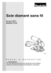
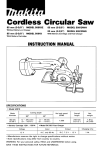
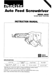
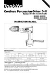
Cordless Cutter
85 mm (3-3/8")MODEL 4191DZ
85 mm (3-3/8")MODEL 419lDWA
With Battery Cartridge and Fast Charger
INSTRUCTION MANUAL
S PEClFICAT10NS
Model 4191D
Blade
diameter
No load speed
Cutting depth
450
(RPM)
Overall
length
weight
0
18 mm
( 0 - 11/16")
1,000
3 1 6 mm
(12-1/2")
2.1 kg
(4.6 Ibs)
900
0
(0
8 5 mm
13-318")
~
~
2 4 mm
15/16")
Battery Cartridge 1222
Voltage
12
v
~
Model DC1410 Fast Charger
I
Input
A.C. only 50 - 6 0 Hz
I
I
output
D.C. 7.2 V
~
14.4 V
Charging time
1 Hr.
IMPORTANT
SAFETY INSTRUCTIONS
(For All Tools)
WARNING: WHEN USING ELECTRIC TOOLS, BASIC SAFETY
PRECAUTIONS SHOULD ALWAYS BE FOLLOWED TO REDUCE
THE RISK OF FIRE, ELECTRIC SHOCK, AND PERSONAL
INJURY, INCLUDING THE FOLLOWING:
READ ALL INSTRUCTIONS.
1. KEEP WORK AREA CLEAN. Cluttered areas and benches invite injuries.
2. CONSIDER WORK AREA ENVIRONMENT. Don't use power tools in damp
or wet locations. Keep work area well lit. Don't expose power tools t o rain.
Don't use tool in presence of flammable liquids or gases.
3.KEEP CHILDREN AWAY. All visitors should be kept away from work area.
Don't let visitors contact tool or extension cord.
4. STORE IDLE TOOLS. When not in use, tools should be stored in dry, and high
or locked-up@ace - out of reach of children.
5. DON'T FORCE TOOL. It will do the job better and safer at the rate for which
it was intended.
6. USE RIGHT TOOL. Don't force small tool or attachment to do the job of a
heavy-duty tool. Don't use tool for purpose not intended; for example, don't
use circular saw for cutting tree limbs or logs.
7. DRESS PROPERLY. Don't wear loose clothing or jewelry. They can be caught
in moving parts. Rubber gloves and non-skid footwear are recommended
when working outdoors. Wear protective hair covering t o contain long hair.
8. USE SAFETY GLASSES. Also use face or dust mask if cutting operation is
dusty.
9. DON'T ABUSE CORD. Never carry tool by cord or yank it to disconnect from
receptacle. Keep cord from heat, oil, and sharp edges.
IO. SECURE WORK. Use clamps or a vise t o hold work. It's safer than using
your hand and it frees both hands t o operate tool.
11. DON'T OVERREACH. Keep proper footing and balance at all times.
12. MAINTAIN TOOLS WITH CARE. Keep tools sharp and clean for better and
safer performance. Follow instructions for lubricating and changing accessories. Inspect tool cords periodically and if damaged, have repaired by authorized service facility. Inspect extension cords periodically and replace if
damaged. Keep handles dry, clean, and free from oil and grease.
13. DISCONNECT TOOLS when not in use, before servicing, and when changing accessories, such as blades, bits, cutters.
2
14. REMOVE ADJUSTING KEYS AND WRENCHES. Form habit of checking to
see that keys and adjusting wrenches are removed from tool before turning
it on.
15. AVOID UNINTENTIONAL STARTING. Don't carry tool with finger on switch.
Be sure switch is OFF when plugging in.
16. OUTDOOR USE EXTENSION CORDS. When tool is used outdoors, use only
extension cords intended for use outdoors and so marked.
17. STAY ALERT. Watch what you are doing, use common sense. Don't operate
tool when you are tired.
18. CHECK DAMAGED PARTS. Before further use of the tool, a guard or other
part that is damaged should be carefully checked t o determine that it will
operate properly and perform its intended function. Check for alignment of
moving parts, binding of moving parts, breakage of parts. mounting, and any
other conditions that may affect its operation. A guard or other part that
is damaged should be properly repaired or replaced by an authorized service
center unless otherwise indicated elsewhere in this instruction manual. Have
defective switches replaced by authorized service center. Don't use tool if
switch does not turn it on and off.
19. GUARD AGAINST ELECTRIC SHOCK. Prevent body contact with grounded
surfaces. For example; pipes, radiators, ranges, refrigerator enclosures.
20. REPLACEMENT PARTS. When servicing, use only identical replacement parts.
21. POLARIZED PLUGS. To reduce the risk of electric shock, this equipment has
a polarized plug (one blade is wider than the other). This plug will fit in a
polarized outlet only one way. If the plug does not fit fully in the outlet, reverse
the plug. If it still does not fit, contact a qualified electrician t o install the
proper outlet. Do not change the plug in any way.
VOLTAGE WARNING: Before connecting the tool to a power source (receptacle,
outlet, etc.) be sure the voltage supplied is the same as that specified on the
nameplate of the tool. A power source with voltage greater than that specified
for the tool can result in SERIOUS INJURY t o the user - as well as damage t o
the tool. If in doubt, DO NOT PLUG IN THE TOOL. Using a power source with
voltage less than the nameplate rating is harmful t o the motor.
IMPORTANT SAFETY INSTRUCTIONS
FOR CHARGER &
BATTERY CARTRIDGE
I. SAVE THESE INSTRUCTIONS - This manual
4
Length of Cord (Feet)
25
50
100
150
AWG Size of Cord
18
18
18
16
ADDITIONAL SAFETY RULES
FOR CHARGER & BATTERY CARTRIDGE
1. Do not charge Battery Cartridge when temperature is BELOW 10°C (5OOF)
or ABOVE 4OoC (104OF).
2. Do not attempt to use a step-up transformer, an engine generator or DC power
receptacle.
3.Do not allow anything t o cover or clog the charger vents.
4. Always cover the battery terminals with the battery cover when the batter.y
cartridge is not used.
5. A battery short can cause a large current flow, overheating, possible burns
and even a breakdown.
(11 Do not touch the terminals with any conductive material.
(21 Avoid storing battery cartridge in a container with other metal objects such
as nails, coins, etc.
(3)Do not expose battery cartridge to water or rain.
6. Do not store the tool and Battery Cartridge in locations where the temperature may reach or exceed 35OC (95OF).
7. Do not incinerate the Battery Cartridge even if it is severely damaged or is
completely worn out. The battery cartridge can explode in a fire.
ADDITIONAL SAFETY RULES
1. Be aware that this is always in an operating condition, because it does not
have t o be plugged into an electrical outlet.
2. Check the wheel carefully for cracks or damage before operation. Replace
cracked or damaged wheel immediately.
3.Use only flanges specified for this tool.
4. Be careful not to damage the spindle, flanges (especially the installing
surface) or bolt. Damage t o these parts could result in wheel breakage.
5. Hold the tool firmly.
6. Keep hands away from rotating parts.
7. Make sure the wheel is not contacting the workpiece before the switch is
turned on.
8. Wait until the wheel attains full speed before cutting.
9. Stop operation immediately if you notice anything abnormal.
IO. Do not attempt t o lock the trigger in the "ON" position.
11. Never attempt to cut with the tool
held upside down in a vise. This
can lead to serious accidents,
because it is extremely dangerous.
12. Before setting the tool down after completing a cut, be sure that the wheel
has come t o a complete stop.
SAVE THESE INSTRUCTIONS.
6
Installing or removing the battery cartridge 1222
*Always switch off the tool before insertion or removal of the battery cartridge.
*To remove the battery cartridge, withdraw
it from the tool while pressing the buttons
on both sides of the cartridge.
*To insert the battery cartridge, align the
tongue on the battery cartridge with the
groove in the housing and slip it until it is
locked with a little click.
*Do not use force when inserting the battery cartridge. If the cartridge does not slide in
easily, it is not being inserted correctly.
Installing the set plate
Always install the set plate when using battery cartridges 1200, 1201, 1201A, 1202 or
1202A. Install the set plate on the tool with
the screw and nut provided as shown in
the figure.
/
Set plate
.
Pan head screw
Installing or removing the battery cartridge 1200,1201,1201A, 1202 and 1202A.
*Always switch off the tool before insertion or removal of the battery cartridge.
*To remove the battery cartridge, pull out
the set plate on the tool and grasp both
sides of the cartridge while withdrawing it
from the tool.
*To insert the battery cartridge, align the
tongue on the battery cartridge with the
groove in the housing and slip it into place.
Snap the set plate back into place. Be sure
to close the set plate fulty before using the
tool.
*Do not use force when inserting the battery cartridge. If the cartridge does not slide in
easily, it is not being inserted correctly.
7
Charging
*Your new battery cartridge is not charged.
You will need to charge it before use. Use
the fast charger Model DC1410 to charge
the battery cartridge.
*Plug the fast charger into the proper N C
Charging light voltage source. The charging light will flash
in green color.
*Insert the battery cartridge so that the plus
and minus terminals on the battery cartridge are on the same sides as their
respective markings on the fast charger.
Insert the cartridge fully into the port so
that it rests on the charser ~ o rfloor.
t
*When the battery cartridge is inserted, the charging light color will change from green to
red and charging will begin. The charging light will remain lit steadily during charging.
*When charging is completed, the charging light color will change from red to green.
*After charging, unplug the charger from the power source. Refer to the table below for
the charging time.
-
I
DC1410
I
1200
I
ADDrox. 4 0 min.
I
~
1201 / 1201A
Approx. 50 min.
1202 I 1 2 0 2 A / 1222
Approx. 60 min.
CAUTION:
*The fast charger Model DC1410 is for charging Makita battery cartridge. Never use it for
other purposes or for other manufacturer’s batteries.
*When you charge a new battery cartridge or a battery cartridge which has not been used
for a long period of time, it may not accept a full charge. This is normal condition and
does not indicate a problem, You can recharge the battery cartridge fully after discharging
it completely and recharging a couple of times.
*If you charge a battery cartridge from a just-operated tool or a battery cartridge which has
been left in a location exposed to direct sunlight or heat for a long time, the charging light
may flash in red color. If this occurs, wait for a while. Charging will begin after the battery
cartridge cools. The battery cartridge will cool faster if you remove the battery cartridge
from the fast charger.
*If the charging light flashes alternately in green and red color, a problem exists and charging is not possible. The terminals on the charger or battery cartridge are clogged with
dust or the battery cartridge is worn out or damaged.
*If you wish to charge two battery cartridge, allow 15 minutes between chargings on the
fast charger.
8
Installing or removing diamond wheel
CAUTION:
Always be sure that the tool is switched off and the battery cartridge is removed before
installing or removing the wheel.
To install the wheel, first loosen the bolt
with the hex wrench and remove the bolt
and the flange. Then mount the wheel, the
flange and the bolt. The wheel should be
mounted with the Makita name on the
flange side.
-
Diamond wheel
Press the shaft lock so that the wheel cannot revolve. Use the hex wrench to tighten
the bolt securely
Shaft lock
-
Hex wrench
To remove the wheel, follow the installation procedure in reverse.
CAUTION:
*When installing the wheel, be sure to tighten the bolt securely.
*Use only the Makita hex wrench to install or remove the wheel.
,
n
installing water supply
Attach the tank holder on the tank. The tank
,-
Tank holder
installing portion
-Tank
Attach the tank holder onto the motor housing. Tighten the screw (B) securely.
Connect the cap on the end of the polyvinyl
tube to the mouth of the tank. Turn the tank
clockwise when making the connection.
Then tighten the screw (A) securely to
secure the tank.
CAUTION:
If you find the polyvinyl tube is bent like a "V" or has been strained excessively after
installing the water supply, loosen the screw (B) and adjust the position of the tank to alleviate the bent, pinched or strained condition.
10
Hex wrench storage
When not in use, the hex wrench can be
conveniently stored.
Hex wrench
4
b
Adjusting the depth of cut
Loosen the screw on the depth guide and move the base up or down. You can read the
depth of cut by aligning the top of the notch in the depth guide with the graduations on its
right side. (Note: This can be done for 0" bevel cutting only.) At the desired depth of cut,
secure the base by tightening the screw.
Depth auide
CAUTION:
*Use a shallow depth of cut when cutting thin workpiece for cleaner, safer cuts.
*After adjusting the depth of cut, always tighten the clamp screw securely.
Bevel cutting
Loosen the screw on the bevel scale plate
on the front of the base. Set for the desired
angle (0" - 45") by tilting accordingly, then
tighten the clamp screw securely.
CAUTION:
After adjusting the depth of cut and bevel cutting angle, be sure to tighten the screw.
Sighting
The front of the base is notched to provide
two guide edges.
For straight cuts, align the edge with 0"
engraved on it with your cutting line on the
workpiece.
For 45" bevel cuts, align the edge with 45"
engraved on it with your cutting line.
Switch action
To prevent the trigger from being accidentally pulled, a lock-off lever is provided.
To start the tool, slide the lock-off lever in
the direction of the arrow and pull the trigger. Release the trigger to stop.
Switch trigger
Lock-off lever
CAUTION:
Before inserting the battery cartridge into the tool, always check to see that the switch
trigger actuates properly and returns to the "OFF" position when released.
Water supply
Remove the cap on the tank and fill through
the hole. Recap the tank. Be sure that the
water cock is turned off when filling the
tank with water.
CAUTION:
When filling the tank with water, be careful not to let the tool get wet
12
Operation
Hold the tool firmly. Set the base plate on
the workpiece to be cut without the wheel
making any contact. Then turn the tool on
and wait until the wheel attains full speed.
Feed water to the wheel by adjusting the
water cock to obtain a gentle flow of water.
Move the tool forward over the workpiece
surface, keeping it flat and advancing
smoothly until the cutting is completed.
Keep your cutting line straight and your
speed of advance uniform.
For fine, clean cuts, cut slowly. (When cutting glass plate 5 mm (3/16”) thick, cut at about
250 mm/min (9-7/8”/min). When cutting tile 10 mm (3/8”) thick, cut at about 300 mm/min
(11-13/16”/min). Also slow down as you complete a cut to avoid breaking or cracking the
workpiece being cut.
CAUTION:
*Be sure to hold the workpiece firmly down on a stable bench or table during operation.
*Do not twist or force the tool in the cut, or the motor may be overloaded or the workpiece may break.
*Do not use the tool with the wheel in an upward or sideways position.
*When cutting glass plate, it is recommended to attach a rubber plate (optional accessory)
on the base of the tool to prevent the workpiece surface from being scratched.
*The wheel for Model 41 91D/DW is a wet-type wheel for glass and tile applications. Be
sure to feed water to the wheel during operation.
*If the cutting action of the wheel begins to diminish, dress the cutting edge of the wheel
using an old discarded coarse grit bench grinder wheel or concrete block.Dress by pressing lightly on the outer edge of the wheel.
CAUTION:
If the tool is operated continuously until the battery cartridge has discharged, allow the
tool to rest for 15 minutes before proceeding with a fresh battery.
13
MAINTENANCE
CAUTION:
Always be sure that the charger is unplugged and the battery cartridge is removed before
attempting to perform inspection or maintenance.
After use
Brush off accumulation of dust on the base
To maintain product SAFETY and RELIABILITY, repairs, maintenance or adjustment should
be performed by Makita Authorized or Factory Service Centers, always using Makita
replacement parts.
14
OPTIONAL ACCESSORIES
The accessories listed in this manual are available at an extra cost from your Makita distributor or
Makita factory service center. Service centers are listed on the warranty card packed with your tool.
CAUTION:
These accessories or attachments are recommended for use with your Makita tool specified in this
manual. The use of any other accessories or attachments might present a risk of injury to persons.
The accessories or attachments should be used only in the proper and intended manner.
Hex wrench
Part No. 783202-0
Battery cartridge 1 2 0 0
Part No. 192271-4
High capacity battery 1201, 1 2 0 2
Part No. 192296-8 (1201)
Part No. 192536-4 (1202)
Fast charger
Model DC1410
Part No. 113 1 50-3
Power display battery (High cap.) 1201A. 1202A
Part No. 192407-5 (1201A)
Part No. 192537-2 ( 1202A)
Battery cover
Part No. 414938-7
High capacity battery 1222
Part No. 192598-2
Diamond wheel
Part No.
1 I 1 E1
724950-8c
724950-8B
I
Dimfr
diF?r
(3-318")
(1 9/32")
85
(3-318")
I
15
(19132")
* S e t plate
Part No. 343579-1
Use
General
purpose
I
Wet
I
For glass
cutting
15
Feb -29-'96
US
85 mm (3-3/8")
CORDLESS CUTTER
Model 4191D
Note: The switch and other part configurations
may differ from country to country.
16
MODEL 4191D
Feb.-29-'96
$&
:I""
,
MACHINE
1
4
5
6
7
8
9
10
11
12
13
14
15
16
17
18
19
20
21
22
23
24
25
26
21
28
29
30
31
32
ji
1
1
1
1
1
1
1
1
1
1
1
3
1
1
1
1
1
1
1
1
1
2
1
1
3
1
1
1
1
DESCRIPTION
1
'i\M
AD:
US
DESCRIPTION
MACHINE
__
Band B
Pan Head Screw M4x25 IWith Washer)
Name Plate
DC Motor 12 V
Motor Housing
Cap
Tank
Pan Head Screw M4x25 IWith Washerl
Tank Holder
Rubber Washer 12
cap
VinylTube 5
Nut
Compression Spring 4
Tapping Screw 4x 18
Lock Oft Lever
Housing Set IWith Item 221
Rubber Sheet
Battery Holder
High Capacity Batlery 1222
Rubber Sheet
Houslng Set IWith Item 171
Pan Head Screw M4x25 IWifh Washer)
Makita Label
Tapping Screw Flange PT 4x30
Tapping Screw Flange PT 4x30
Hex Nul M 5
Tapping Screw 4x18
Switch
Hex Nut M 4
S w t c h Lever
Plane Bearing 4
37
38
39
40
41
42
43
44
45
46
47
48
49
50
51
52
53
54
55
56
57
58
59
60
61
62
63
64
1
1
1
I
1
1
I
1
1
1
1
1
1
1
1
1
1
1
1
1
1
3
1
1
1
1
1
1
Gear Complete 8 - 6 8
Thin Washer 4
Plane Bearing 4
Retaining Ring 5-8
Helical Gear 3 3
Flat Washer 8
Ball Bearing 608LB
COmpreSSlOn Spring 7
Pl" 5
Water Supply Cock Complete
Screw M5x 10
Screw M5x10
Spring Washer 5
Flat Washer 5
Base
Spring Pin 4 - 4 0
Flat Washer 5
Sprlog Washer 5
Screw M5x 10
Stop Ring E - 4
Nozzle
Woodruff Key 3
Splndle
Ball Bearing 6OOOLLP
Blade Case
Tapping Screw 4x18
Bearing Box
Packing
RetalW,
Inner Flange 28
Outer Flange 28
Hex Socket Head Bolt M5x12
17
Recycling the Battery
The only way to dispose of a Makita battery is
to recycle it. The law prohibits any other
method of disposal.
I
Ni-Cd
I
To recycle the battery:
1. Remove the battery from the tool.
2. a). Take the battery to your nearest Makita Factory Service Center
or
b). Take the battery to your nearest Makita Authorized Service Center or
Distributor that has been designated as a Makita battery recycling location.
Call your nearest Makita Service Center or Distributor to determine the location
that provides Makita battery recycling. See your local Yellow Pages under
"Tools-Electric'
MAKITA LIMITEDONE YEAR WARRANTY
Warranty Policy
Every Makita tool is thoroughly inspected and tested before leaving the factory. It is warranted to
be free of defects from workmanship and materials for the period of ONE YEAR from the date of
original purchase. Should any trouble develop during this one-year period, return the COMPLETE
tool, freight prepaid, to one of Makita's Factory or Authorized Service Centers. If inspection shows
the trouble is caused by defective workmanship or material, Makita will repair (or at our option,
replace) without charge.
This Warranty does not apply where:
e repairs have been made or attempted by others:
e repairs are required because of normal wear and tear:
e The tool has been abused, misused or improperly maintained;
e alterations have been made to the tool.
I N NO EVENT SHALL MAKITA Bk. LIABLE FOR ANY INDIRI:CT, INCIDENTAL OR CONSEQUENTIAL DAMAGES FROM THE SALE OR USE OF THE PRODUCT. THIS DISCLAIMER
APPLIES BOTH DURING AND AFTER THE TERM OF THIS WARRANTY.
RANTIES, INCLUDING IMPLIED
S FOR A SPECIFIC PURPOSE;'
y also have other
limitation of inci
Makita Corporation of America
2650 Buford Hwy., Buford, GA30518
MCA 6/96
884068A064
PRINTED IN USA
19%-7-4D