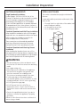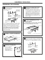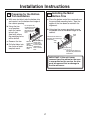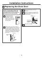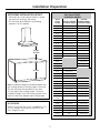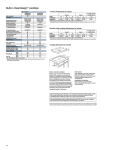
1
The Kitchen Loft 90 Wood Street Lynbrook, NY 11563 Tel/Fax: 516/599-5946 www.StephenWangel.com Schedule of appliances: Client Name: ABEL Appliance Brand Model Type Dimensions Door Panel ? Refrigerator A GE PGCS1PJXSS FRENCH DOOR 36 X 70 X 24 NO Refrigerator B — Wine Cooler — Beverage Center — Dishwasher A GE PDWF580PSS UNDER CTR 24 X 34 X 24 NO Dishwasher B — PSB2201NSS SPEED COOK 30 X 20 NO Microwave GE ADVANTIUM MW Trim Kit N/A Cook top GE PHP900SMSS INDUCTION 30” NO Wall Oven GE PT916SMSS CONVECTION 30” NO Freestanding Range — Hood/Blower Unit GE MONOGRAM Trash Compactor — Main Sink NO ZV830SMSS CHIMNEY 30” NO TBD* NO 2nd Sink (kosher) — NO Prep Sink — NO END OF LIST *A 36” cabinet is provided for the sink. Consult manufacturer recommendations when choosing a sink. Client acknowledges that these are the correct and only appliances that will be incorporated into the kitchen design. Door style panels for appliances will only be furnished when the door panel column is marked “Yes” for the appropriate appliance. Once a factory order is placed for cabinetry, we cannot change the design to accommodate different appliances. Acknowledged: ___________________________________________ Date: __________________ PGCS1PJXSS - GE Profile™ 20.7 Cu. Ft. Refrigerator with Armoire Styling - Product ... SEARCH Page 1 of 3 Select Category Shopping Cart | Where To Buy HOME PRODUCTS SERVICE & SUPPORT DESIGN CENTER GE Profile™ 20.7 Cu. Ft. Refrigerator with Armoire Styling Model#: PGCS1PJXSS Print This Page Features & Photos Product Details Parts & Related Products Product Documentation APPROXIMATE DIMENSIONS (HxDxW) 69 5/8 in x 31 in x 35 3/4 in CAPACITY Total Capacity (cubic feet) 20.70 cu ft Fresh Food Capacity 14.60 cu ft Freezer Capacity 6.10 cu ft Shelf Area 23.90 sq ft Photo Gallery FEATURES Configuration French Door & Double Drawer Temperature Management System ClimateKeeper™ Temperature Management Features TurboCool™ Setting 4 Electronic Sensors Multiflow Air Tower Defrost Type Frost Free Control Type 4.3" Color LCD Upfront Electronic Digital Temperature Display Dispenser External Water Dispenser Features Door Alarm Icemaker Factory-Installed Water Filtration GE Water Filtration 1 Year Filter Change Indicator Electronic - External Fresh Food Cabinet Shelves 4 Fresh Food Cabinet Shelf Features 4 Split Adjustable QuickSpace™ Shelf - 1 3 Slide-Out 3 Spill Proof Glass Fresh Food Door Bins 1 Fixed Fresh Food Door Features ClearLook™ Bins Gallon Storage 3 Adjustable 1 Fixed Fresh Food Features Dairy Compartment Snugger Clips - 2 This information provided by DCF Fabrication www.StephenWangel.com Email This Page PGCS1PJXSS - GE Profile™ 20.7 Cu. Ft. Refrigerator with Armoire Styling - Product ... Meat Pan Full-Width with Temperature Control Vegetable / Fruit Crisper(s) 2 Adjustable Humidity Freezer Storage Basket 3 Sliding (2 Full-Width/1 Split) Freezer Features GE Reveal® Interior Light Beverage Feature In-the-Door Can Rack Exterior Style Free-Standing Interior Lighting LED Leveling System 4 Point Front Adjustable Sweet Spot Shelf Yes ECONOMICAL / QUIET Quiet Package Premium Quiet Design Energy Saver Yes APPEARANCE Color Appearance Stainless Steel Counter-Depth Design Yes Dispenser Color Color-Matched Door Stops Yes Door Style Contoured with Top & Bottom Bevels Door Swing Hinges on Left & Right Easy to Remove Door Gaskets Yes Handle Sculptured Stainless Steel Textured Steel Case Gray - Galvanized Steel Adjustable Rollers Front and Rear WEIGHTS & DIMENSIONS Approximate Shipping Weight 373.00 lb Net Weight (lbs.) 343.00 lb Overall Depth 31 in Overall Height 69 5/8 in Overall Width 35 3/4 in Case Depth Without Door (in.) 23-7/8 Depth with Door Open 90° (in.) 43-1/8 Depth Without Handle (in.) 28-1/2 Height to Top of Case (in.) 69 Width w/Door Open 90 Degrees Incl. Handle (in.) 40-7/8 Back Air Clearances (in.) 1/2 Side Air Clearances (in.) 1/8 Top Air Clearances (in.) 1 POWER / RATINGS Volts/Hertz/Amps 120V ; 60Hz ; 15A WARRANTY Parts Warranty Limited 1-year entire appliance Limited 5-year sealed refrigerating system Labor Warranty Limited 1-year entire appliance This information provided by DCF Fabrication www.StephenWangel.com Page 2 of 3 PGCS1PJX GE Profile™ 20.7 Cu. Ft. French Door Refrigerator with Double Freezer drawers and External Water Features and Benefits • Counter-Depth Design - Offers a built-in look without the built-in expense • Stainless-Steel Doors with Top & Bottom Bevels - Provides a striking finish and contoured doors to accentuate kitchen decor • Two Freezer Drawers - Add convenience by allowing easy access and organization of frozen foods TEMPERATURE SET • External Water Dispenser with LCD Controls - Offers fresh water and also makes it easy to monitor all the functions of the refrigerator ENERGY SAVER TURBOCOOL LIGHT RESET FILTER Hold 3 seconds to Reset REFRIGERATOR FREEZER DOOR ALARM LOCK Hold 3 seconds • ClimateKeeper™ Temperature Management System - Digital controls and electronic sensors give you a greater degree of control over food preservation • LED Lighting - Casts a clean, beautiful light throughout the fresh food area of the refrigerator • Factory-Installed Icemaker with Water Filtration System - Automatically creates fresh, filtered ice cubes • Freshness Center™ - Offers maximum convenience by utilizing two humidity-controlled drawers and 1 full-length drawer for large storage • Multi-Level Slide 'n Store™ Basket System - Includes three full-extension baskets for tremendous storage flexibility and keeps contents perfectly in place • Condiment Bin and Beverage Rack - Provides convenient storage for canned drinks and condiments • QuickSpace™ Shelf - Quickly slides out of the way to make room for tall items • TurboCool™ Setting - Cools the refrigerator quickly after frequent door openings • Secure-Close Door System - Securely pulls the door shut, even after you release the handle • Model PGCS1PJXSS - Stainless Steel Specification Created 10/07 210862 PGCS1PJX GE Profile™ 20.7 Cu. Ft. French Door Refrigerator with Double Freezer drawers and External Water Air Clearances Overall Dimensions Dimensions and Installation Information (in inches) Height to top of hinge (in.) A 69-5/8 Height to top of case (in.) B 69 Case depth without door (in.) C 23-7/8 Case depth less door handle (in.) D 28-1/2 Case depth with door handle (in.) E 31 Depth with fresh food door open 90° (in.) F 43-1/8 Width (in.) G 35-3/4 Width with door open 90° inc. door handle (in.) H 40-7/8 Each side (in.) 1/8 Top (in.) 1 Back (in.) 1/2 Front View Top View For answers to your Monogram,® GE Profile™ or GE® appliance questions, visit our website at ge.com or call GE Answer Center® service, 800.626.2000. Listed by Underwriters Laboratories Specification Created 10/07 210862 PDWF580PSS - GE Profile™ Dishwasher with SmartDis... Page 1 of 3 Monday, February 23, 2009 SEARCH Select Category Shopping Cart | Where To Buy HOME PRODUCTS SERVICE & SUPPORT DESIGN CENTER GE Profile™ Dishwasher with SmartDispense™ Technology Model#: PDWF580PSS Print This Page Features & Photos Product Details Parts & Related Products Product Documentation $1449 Est. Retail Price Current Rebate APPROXIMATE DIMENSIONS (HxDxW) 34 in x 24 3/4 in x 24 in FEATURES Photo Gallery ENERGY STAR® Qualified Yes Style Built-In Tub and Door Liner Stainless Steel Tub Type Tall Tub Control Type Electronic Light-Touch 12 Touchpads Front Controls Dishwasher Control Features Start / Cancel / Reset Pad Last Cycle Memory Child Lock 3 Digit Countdown Display with 5 Cycle Progress Indicator Status Lights Audible End-of-Cycle Signal Wash System 6-Level BrilliantClean™ Wash System Features Dual Pumps and Motors Piranha™ Hard Food Disposer Automatic Temperature Control Automatic Temperature Sensing Drain Hose Sensor CleanSensor™ Wash Arms 3-Direct Feed Lower Middle Upper Water Filtration System 100% Triple with ExtraFine™ Filter Dispenser SmartDispense™ II Technology Bulk Detergent Dispenser with Refill Light Rinse Aid with Indicator and Adjustment Number of Cycles 8 Dishwasher Cycles Normal Wash Anti-Bacteria (NSF Certified) Single Rack Wash Also available in... White on White PDWF500PWW $1349 ERP Black on Black PDWF500PBB $1349 ERP This information provided by The Kitchen Loft www.StephenWangel.com Email This Page PDWF580PSS - GE Profile™ Dishwasher with SmartDis... Page 2 of 3 Monday, February 23, 2009 SpeedCycle™ (Wash and Dry) DeepClean™ Hand/Gentle Plastics Rinse Only / Hold Number of Options 6 Dishwasher Options Delay Start 1-24 Hr. with Countdown Automatic HotStart™ Heated Dry On/Off PreWash Steam PreWash TempBoost Rack Features ExtraBasket Cutlery Tray 4 Knife Capacity 3 Pearlescent Utility Shelves with StemSafe Upper CleanTip™ Tines 4 Fold-Down Tines with 2 Multi-Position Upper 100% Fold-Down Tines Lower Adaptable Bowl Tines Upper Rack Handle Lower Rack Handle Easy-Glide Roller System 3 Piece Silverware Basket with Cell Covers and Swivel Handle Racking System Nylon Towerless Pearlescent™ Racks Number of Place Settings Up to 16 Upper Rack Removable 4-Position Adjustable Deep Tiered Angled Rack Dry System™ Nylon Lower Rack Towerless Dishwasher Drying Features Multi-Wattage Calrod Heater Convection Dry Exterior Style Traditional Latch Squeeze Leveling System Leveling Screws Steel Door Yes ECONOMICAL / QUIET Quiet Package QuietPower™ 50 Quiet Features Sealed Toe Kick Quiet Water Valve Quiet Detergent Cup Tub Collar Trim Active Vent System Motor Type QuietPower™ Motor Outer Wrap Full-wrap Blanket Bitumen Door Insulation Insulation Bitumen APPEARANCE Color Appearance Stainless Steel Door Style Long Door Installation Hard Countertop Ready This information provided by The Kitchen Loft www.StephenWangel.com PDWF580PSS - GE Profile™ Dishwasher with SmartDis... Page 3 of 3 Monday, February 23, 2009 Upscale Flush Design Door Appearance Stainless steel one-piece contour door Control Panel Color Black WEIGHTS & DIMENSIONS Approximate Shipping Weight 115.00 lb Net Weight (lbs.) 110.00 lb Overall Height 34 in Height w/Legs Extended (in.) 35 Overall Depth 24 3/4 in Overall Width 24 in POWER / RATINGS Calrod Heater Watts 875 Max. Volts/Hertz/Amps 120V ; 60 Hz ; 9.1 A Ad Designer Submitted WARRANTY Parts Warranty Limited 1-year entire appliance Limited 5-year racks/electronic control board Limited lifetime of product tub/door liner Labor Warranty Limited 1-year entire appliance Limited lifetime of product tub/door liner Warranty Notes For models produced on or after January 1, 2006 See written warranty for full details Corporate | Careers | Press Room | Recall Information Accessibility Statement | Contact Us | Site Map Privacy Policy | Terms of Use Sign up for our e-Newsletter: Enter E-Mail Address View current issue Copyright 2009 General Electric Company This information provided by The Kitchen Loft www.StephenWangel.com PDWF500/580P GE Profile™ Dishwasher with SmartDispense™ Technology Dimensions and Installation Information (in inches) Electrical Rating Voltage AC.......................................................... Hertz..................................................................... Total connected load amperage............. Calrod® heater watts max......................... 25-1/4 MAX. 120 60 9.1 875 24 22-1/2 For use on adequately wired 120-volt, 15-amp circuit having 2-wire service with a separate ground wire. This appliance must be grounded for safe operation. Installation Information: Before installing, consult installation instructions packed with product for current dimensional data. 27-1/2 33-13/16" MIN. adj. to 35" 21-1/4 $PVOUFSUPQ 4 (Adjustable) 5IJTXBMMBSFB NVTUCFGSFFPG QJQFTPSXJSFT .*/ 4 &MFDUSJDBM XJSJOHJT GSPN DBCJOFU )PU XBUFS MJOFPO UP 6OEFSTJEF MFGU PGDPVOUFSUPQ UPGMPPS &MFDUSJDBM XJSJOHPO SJHIU 1MVNCJOHBOEFMFDUSJDBM TFSWJDFNVTUFOUFS JOTJEFTIBEFEBSFB .*/GSPNXBMM 'SPNXBMM For answers to your Monogram,® GE Profile™ or GE® appliance questions, visit our website at ge.com or call GE Answer Center® service, 800.626.2000. .*/ Listed by Underwriters Laboratories As an ENERGY STAR® partner, GE has determined that this product meets the ENERGY STAR guidelines for energy efficiency. Specification Created 8/08 250222 PDWF500/580P GE Profile™ Dishwasher with SmartDispense™ Technology Features and Benefits • SmartDispense™ Technology - Holds up to 47 fl. oz. of detergent and dispenses it based on water hardness and soil levels • DeepClean™ Cycle with SmartDispense II Technology - Uses SmartDispense II to inject a precise amount of detergent multiple times in the main wash to maximize cleaning power and scrub away hard-to-remove foods • Steam Pre-Wash Option - Helps to loosen tough soils before any cycle • Angled Rack Dry™ System - Rack allows dishes to rest at an angle, so water runs off and drying time is reduced • Four-Position Adjustable Upper Rack - Easy-to-use mechanism allows the upper rack to be moved up, down or diagonally for additional loading flexibility • Single Rack Wash™ Selection - Perfect for smaller loads or for cleaning glasses only, washing just the upper rack of dishes using less water and energy • 100% Fold-Down Tines and Adaptable Bowl Tines in Lower Rack - Racks can secure multiple bowls or fold down for additional flexibility • Model PDWF580PSS - Stainless steel (shown) • Model PDWF500PWW - White on white • Model PDWF500PBB - Black on black 8.8.8 Specification Created 8/08 250222 PSB2201NSS - GE Profile Advantium® Wall Oven - Pro... Page 1 of 3 Monday, February 23, 2009 SEARCH Select Category Shopping Cart | Where To Buy HOME PRODUCTS SERVICE & SUPPORT DESIGN CENTER GE Profile Advantium® Wall Oven Model#: PSB2201NSS Print This Page Features & Photos Product Details Parts & Related Products Product Documentation $2349 Est. Retail Price Current Rebate APPROXIMATE DIMENSIONS (HxDxW) 19 1/32 in x 21 1/2 in x 29 25/32 in CAPACITY Total Capacity (cubic feet) 1.70 cu ft FEATURES Photo Gallery Also available in... White PSB2200NWW $2149 ERP Black PSB2200NBB $2149 ERP ENERGY STAR® Qualified No Control Type Glass Touch Controls; Dial Cooking Technology Advantium Microwave Watts (IEC-705) 950.00 W Cooking Modes Speedcook Microwave Convection Bake Warm/Proof Broil Toast Style Built-In Program Cooking Over 175 Pre-Programmed Speed Cook Recipes Convection Cooking Controls Bake Broil Advantium® Cooking Controls Clock Demo Mode Electronic Scrolling Digital Display Help Pad Repeat Last Time Preference Variable Scroll Speed Microwave Sensor Cooking Controls Beverage Popcorn Potatoes Reheat Vegetables Microwave Oven Control Features Add 30 Seconds Cooking Complete Reminder Cooking Guide Display On/Off This information provided by The Kitchen Loft www.StephenWangel.com Email This Page PSB2201NSS - GE Profile Advantium® Wall Oven - Pro... Page 2 of 3 Monday, February 23, 2009 Auto & Time Defrost Clock Custom Recipe Saver Help Pad Microwave Oven Interior Stainless Steel Ceramic Pan Yes Convection Tray Yes Display On/Off Yes Express Cook Yes Grill Pan Yes Interior Oven Light Yes Oven Cooking Modes Speed Bake Rack Type Wire Oven Rack Reminder (24 hr) Yes Soften/Melt Yes Sound Volume Control Yes Time Cook Yes Timer (On/Off) Yes Turntable Yes- 16" diameter Turntable Size (in.) 16 APPEARANCE Color Appearance Stainless Steel Door Color Black/Stainless Steel Handle Yes Oven Door Features Oven Window WEIGHTS & DIMENSIONS Approximate Shipping Weight 87.00 lb Cabinet Width 30.00 in Cavity (W x H x D) 20-1/16 x 8-1/2 x 17 Height (Front) (ins.) 21-7/8 Net Weight (lbs.) 77.00 lb Overall Depth 21 1/2 in Overall Height 19 1/32 in Overall Width 29 25/32 in POWER / RATINGS Amps 240V/208V 30 Input Volts/Hertz 240/208V/60Hz Ad Designer Submitted ACCESSORIES Cookbook Yes Metal Oven Pan Yes WARRANTY Parts Warranty Limited 1-year entire appliance Limited 5-year magnetron tube Labor Warranty Limited 1-year entire appliance Warranty Notes See written warranty for full details This information provided by The Kitchen Loft www.StephenWangel.com PSB2201NSS GE Profile Advantium® 240 Wall Oven Note: Cabinets installed adjacent to wall ovens must have an adhesion spec of at least a 194°F temperature rating. Note: 2" minimum between cutouts when installed above warming drawer or single wall oven. Installation Information: Before installing, consult installation instructions packed with product for current dimensional data. $VUPVUXJEUI &YDMVEJOH )BOEMF $POEVJU MPOH +VODUJPOCPYMPDBUJPO " ) $VUPVUEFQUI " # $VUPVUIFJHIU 3FRVJSFE DVUPVUMPDBUJPO NJOJNVN GSPNGMPPS $BCJOFUXJEUI # % .*/CFUXFFODVUPVUT SFDPNNFOEFE.*/SFRVJSFE &YDMVEJOH )BOEMF 8 +VODUJPO CPY MPDBUJPO 7PMU NPEFMTPOMZ " # $POTUSVDU4PMJE#PUUPN .*/1MZXPPE4VQQPSUFECZ YPSY3VOOFSTBMM'PVS4JEFT .VTU4VQQPSUMCTGPS"EWBOUJVN .VTU4VQQPSUMCTGPS8BMM0WFO $POEVJU MPOH $POTUSVDU4PMJE #PUUPN.JO 1MZXPPE 4VQQPSUFECZ YPSY 3VOOFSTBMM 'PVS4JEFT .VTU4VQQPSU MCT DVUPVUIFJHIU DVUPVUXJEUI .*/CFUXFFODVUPVUT .JOBCPWFUPFLJDLPSBEKVTU UP PWFOJOTUBMMBUJPOIFJHIU " "MMPXPWFSMBQPGPWFO PWFSCPUUPNFEHFPGDVUPVUBOEBMMPX A=Allow 7/8” overlap of oven over bottom and 1/4" overlap at top edges of cutout. B=Allow 2-1/8” for overlap of oven over side edges of cutout. $- A=Allow 7/8” overlap of oven over bottom and 1/4" overlap at top edges of cutout. B=Allow 2-1/8” for overlap of oven over side edges of cutout. YTPS FRVJWBMFOU TPMJEGMPPS Cabinet Width W Width H Height (inches) For answers to your Monogram,® GE Profile™ or GE® appliance questions, visit our website at ge.com or call GE Answer Center® service, 800.626.2000. PSB2200/1 without accessory drawer PSB2200/1 with accessory drawer 4VJUBCMF CSBDJOH UPTVQQPSU SVOOFST PWFSDFOUFSMJOF PGDBCJOFU 30 30 29-25/32 29-25/32 19-1/8 22-1/4 D Depth Z Cutout Depth X Cutout Width Y Cutout Height (minimum) 21-1/2 25-1/8 17-1/2 23-1/2 21-3/4 25-1/8 to 28-1/2* 21 23-1/2 (excluding handle) *For existing cutouts a maximum width of 28-1/2" is acceptable Listed by Underwriters Laboratories .VTUTVQQPSUMCT Specification Created 9/08 240441 PSB2201NSS GE Profile Advantium® 240 Wall Oven Preparation WITH an Accessory Drawer Prepare the opening The Advantium 240V can be installed in combination with other GE/Monogram appliances. Always follow each product's Installation Instructions to compete the installation. Single Advantium 240V Installation: Order a 30" wide single oven cabinet or cut the opening in a wall to the dimensions shown. * For existing cutouts, a 23-1/2” 30” maximum width of 28-1/2" is acceptable. If the opening is slightly wider, secure a furring 25-1/8” Min.* strip on each side of the cutout for securing the oven. • Always maintain 36-3/4" 21” minimum height from Construct Base the floor to the cutout in Min. 3/8” Plywood any single or combined Supported by 2x4 or 2x2 36-3/4” installation. Runners all Min. • Allow 3/4" to 2-1/8" case trim Four Sides overlap on the sides and 7/8" overlap on the bottom of the opening for all models. The amount of overlap on the sides depends on the actual cutout width. Allow 1-1/4" case trim overlap on the top for models PSB2200 and PSB2201 and for models ZSC2200, ZSC2201 and ZSC2202. • Oven overlaps will conceal cut edges on all sides of the opening. ® ™ For answers to your Monogram, GE Profile or GE® appliance questions, visit our website at ge.com or call GE Answer Center® service, 800.626.2000. Prepare the opening (cont.) When installed over a single oven or a warming drawer, allow at least 2" between the two openings. This separation will provide clearance for bottom overlap of the Advantium 240V and the other appliance overlaps. Construct a solid oven floor of 3/8" min. thick plywood supported by 2 x 4 or 2 x 2 runners on all sides. • the support must be level and rigidly mounted, flush with the bottom edge of the cutout. 23-1/2” 30” 25-1/8” Min.* 21” Construct Solid Bottom Min. 3/8” Plywood Supported by 2x4 or 2x2 Runners all Four Sides 2” Min. (3” recommended) Per warming drawer requirement 36-3/4” Min. * For existing cutouts, a maximum width of 28-1/2" is acceptable. If the opening is slightly wider, secure a furring strip on each side of the cutout for securing the oven. Note: Additional clearances between the cutouts may be required. Check to be sure the oven supports above the Warming Drawer location do not obstruct the required interior depth and height. See Warming Drawer installation instructions for details. Installation over a GE/Monogram Oven and Warming Drawer: 30” 23-1/2” 25-1/8” Min.* 21” Construct Solid Bottom Min. 3/8” Plywood Supported by 2x4 or 2x2 Runners all Four Sides 2” Min. (3” recommended) Per Oven Requirement 2” Min. 45-1/4” Min. Per warming drawer requirement * For existing cutouts, a maximum width of 28-1/2" is acceptable. If the opening is slightly wider, secure a furring strip on each side of the cutout for securing the oven. Note: Additional clearances between the cutouts may be required. Check to be sure the oven supports above the Warming Drawer location do not obstruct the required interior depth and height. See Warming Drawer installation instructions for details. CAUTION: For personal safety, the mounting surface must be capable of supporting the cabinet load, in addition to the added weight of this approximate 80-pound oven and 30pound drawer, plus additional oven loads of up to 50 pounds or a total weight of 160 pounds. Listed by Underwriters Laboratories Specification Created 9/08 240441 PSB2201NSS GE Profile Advantium® 240 Wall Oven Features and Benefits • Speedcook Technology - Cooks up to 8 times faster than a conventional oven OVEN MICROWAVE CONV • 4 Ovens in 1 to Meet Your Cooking Needs - Speedcook, True European Convection, Warming/Proofing, Sensor Microwave SPEED COOK BAKE BROIL COOK CUSTOM WARM PROOF DEFROST SPEED COOK EXPRESS REHEAT FAVORITE RECIPES TIMER START PAUSE CLEAR OFF BACK HELP POWER TEMP OPTIONS • Optimizes cook time for consistent results • Saves valuable time by eliminating preheating • 16" Turntable - Allows complete rotation of a 9" x 13" casserole dish • Over 175 preprogrammed recipes • Full-width oven rack for multi-level cooking • Includes speedcooking grill tray for preparing meats • Model PSB2201NSS - Stainless steel Accessories: For answers to your Monogram,® GE Profile™ or GE® appliance questions, visit our website at ge.com or call GE Answer Center® service, 800.626.2000. Optional Storage Drawer Available (JX2201NSS) Specification Created 9/08 240441 Installation Preparation ELECTRICAL REQUIREMENTS INSTALL JUNCTION BOX Single Speedcook Installation The conduit is located at the top right on the back of the oven. Product rating is 120/208 or 120/240 volt, 60 Hz, 30 amps. This product must be connected to a supply circuit of the proper voltage and frequency and protected by a time delay fuse or circuit breaker. Power should be supplied from a separate, dedicated 30-ampere branch circuit. Wire size must conform to the requirements of the National Electrical Code or the prevailing local code. Locate and install the junction box within reach of the oven conduit. • Through the left or right sides of the cabinet wall and into adjacent cabinet. • Or, through the cutout floor. • Or, in the upper cabinet. Combined Speedcook and Wall Oven Installation When installed in combination with a GE/Monogram single wall oven, use separate electrical junction boxes. Refer to single oven installation instructions for electrical requirements of that product. These connections must be made by a qualified electrician. All electrical connections must meet National Electrical Code or prevailing local codes. Cutout Height Combined Speedcook and Warming Drawer Installation When installing the Speedcook oven over a GE or Monogram electric warming drawer, a separate 120V, 60Hz, properly grounded receptacle must be installed. See instructions packed with the warming drawer. WARNING • The electrical power to the oven branch circuit must be shut off while line connections are being made. • Use copper wiring only. • Electrical ground is required on this appliance. The free end of the green wire (ground wire) must be connected to a suitable ground. This wire must remain grounded to the oven. • If cold water pipe is interrupted by plastic, non-metallic gaskets, union connections or other insulating materials, DO NOT use for grounding. • DO NOT ground to a gas pipe. • DO NOT have a fuse in the NEUTRAL or GROUNDING circuit. A fuse in the NEUTRAL or GROUNDING circuit could result in an electrical shock. • Check with a qualified electrician if you are in doubt as to whether the appliance is properly grounded. Failure to follow these instructions could result in serious injury or death. 4 Installation Preparation Preparation WITHOUT an Accessory Storage Drawer PREPARE THE OPENING (CONT.) PREPARE THE OPENING (CONT.) Installation over a GE/Monogram Oven: Installation over a GE/Monogram Oven and Warming Drawer: 30” 23-1/2” 25-1/4” 17-1/2” Construct Solid Bottom Min. 3/8” Plywood Supported by 2x4 or 2x2 Runners all Four Sides 30” 23-1/2” 25-1/4” 2” Min. (3” recommended) 17-1/2” Per Oven Requirement Construct Solid Bottom Min. 3/8” Plywood Supported by 2x4 or 2x2 Runners all Four Sides 2” Min. (3” recommended) Per Oven Requirement 45-1/4” Min. 45-1/4” Min. • If you are replacing a GE/Monogram electric double oven with the combined installation of an Advantium 240V and a single oven, use the dimensions shown. The middle rail separating the two openings may need to be larger than the 2” minimum shown. 2” Min. Per warming drawer requirement NOTE: Additional clearances between the cutouts may be required. Check to be sure the oven supports above the Warming Drawer location do not obstruct the required interior depth and height. See Warming Drawer installation instructions for details. CAUTION: For personal safety, the mounting surface must be capable of supporting the cabinet load, in addition to the added weight of this approximate 80-pound oven, plus additional oven loads of up to 50 pounds or a total weight of 130 pounds. 6 Installation Instructions 1 REMOVE THE PACKAGING AND PARTS • Remove all packing material and tape. • Locate parts package containing mounting screws. • Remove the oven from the carton. Do not lift unit by handle or conduit. Two people are required to lift this oven. • Open the door and remove any packaging in oven. Owner’s Manual Rack Owner’s Manual Installation Instructions Bottom Trim Cooking Guide Cook Book Glass Tray Metal Trays (2) 6 Brass Screws (3 required, 3 extra) Cooking Guide 5 Color Matched Screws (4 required, 1 extra) IMPORTANT: If installing the Advantium 240V Oven with an accessory storage drawer, read the storage drawer assembly instructions to assemble the products together before proceeding to Step 2. Turntable Ring Metal Grill Tray 9 Installation Instructions 2 ROUTE CONDUIT THROUGH CUTOUT (CONT.) 2 ROUTE CONDUIT THROUGH CUTOUT CAUTION: Two people are required to lift When connecting to a 3-conductor branch circuit: • Connect oven red lead to branch circuit red lead. • Connect oven black lead to branch circuit black lead. • Connect oven green ground lead and white lead to branch circuit neutral (white or gray). the oven into the opening. Grasp the bottom at front and rear. Discard foam base. DO NOT USE HANDLE OR CONDUIT TO LIFT THE OVEN. DAMAGE WILL OCCUR. With oven in front of the cabinet opening: • Insert conduit into cabinet opening. Connect oven wiring and branch circuit. • Lift the oven into the opening while continuing to feed the conduit in the direction of the installed junction box. Be sure the conduit does not get pinched between the back of the oven and the cabinet wall. • Leave oven a few inches forward of the cabinet front frame. Do not push the unit all of the way into the cutout. When connecting to a 4-conductor branch circuit: • Connect oven red lead to branch circuit red lead. • Connect oven black lead to branch circuit black lead. • Break connection between oven white lead and oven green ground lead. • Connect oven white lead to branch circuit neutral lead (white or gray). • Connect oven green ground lead to branch circuit ground lead (green or bare copper). (Oven shown without accessory storage drawer.) WARNING • Disconnect power to the junction box before making the electrical connection. • Electrical ground is required on this appliance. • Do not connect the electrical supply until appliance is permanently grounded. GROUNDING INSTRUCTIONS This appliance must be connected to a grounded, metallic, permanent wiring system, or an equipment grounding connector should be run with the circuit conductors and connected to the equipment grounding terminal or lead on the appliance. Failure to follow these instructions could result in fire, personal injury or electrical shock. 10 Installation Instructions 4 INSTALL MOUNTING SCREWS 3 INSTALL BOTTOM TRIM NOTE: If installing the Advantium 240 Oven with an accessory storage drawer, the bottom trim is not required. Proceed to Step 4. • Align bottom trim tabs to slots in the bottom of the oven. • Slide the oven the remaining way into the opening so that the side flanges and control panel are against the cabinet frame. Make sure that the oven is centered in the opening. • Open the door, place a turntable tray in the oven and make sure that the tray in the unit is level. • Drill pilot holes through the side flanges. • Drive the color matched screws into the side flanges. It is recommended that the screws be hand tightened. • Secure the bottom trim to the bottom of the oven using 3 brass screws provided. If installing oven with an accessory storage drawer: • Open the drawer. • Drill pilot holes through the side flanges. • Drive color match screws into the side flanges. It is recommended that the screws be hand tightened. 5 FINALIZE INSTALLATION • Turn power on at the source. The interior light should come on when the door is opened. • Refer to Owner’s Manual for operating instructions. 11 PHP900SMSS - GE Profile™ 30" Electric Induction Cooktop - Product Details SEARCH Page 1 of 2 Tuesday, February 24, 2009 Select Category Shopping Cart | Where To Buy | en español HOME PRODUCTS SERVICE & SUPPORT DESIGN CENTER GE Profile™ 30" Electric Induction Cooktop Model#: PHP900SMSS Print This Page Features & Photos Product Details Parts & Related Products Product Documentation $2049 Est. Retail Price Current Rebate APPROXIMATE DIMENSIONS (HxDxW) 3 1/4 in x 21 3/8 in x 29 3/4 in FEATURES Photo Gallery Also available in... Black PHP900DMBB $1849 ERP ENERGY STAR® Qualified No Cooktop Surface Glass Ceramic Black Glass Ceramic Cooktop Burner Type 4 Induction Style Smoothtop 11" Heating Element 1 (3700 Watts) 6" Heating Element (s) 1 (1800 Watts) 7" Heating Element(s) 2 (2500 Watts) Control Type Electronic Touch Cooktop Control Features Child Lock Pan Presence Sensor Control Location Front Center Indicator Lights 4 Hot Surface Surface Element "ON" Kitchen Timer Yes - Minute Power Cord Length 36" This information provided by The Kitchen Loft www.StephenWangel.com Email This Page PHP900SMSS - GE Profile™ 30" Electric Induction Cooktop - Product Details Power Level Indicator Page 2 of 2 Tuesday, February 24, 2009 Digital 7 Segment APPEARANCE Color Appearance Stainless Steel Frame Color / Material Stainless Steel WEIGHTS & DIMENSIONS Approximate Shipping Weight 46.00 lb Cooktop Size (in.) 30.00 in Cutout Dimensions (Width x Depth) (In.) 28-1/2 x 19-5/8 Net Weight (lbs.) 41.00 lb Overall Depth 21 3/8 in Overall Height 3 1/4 in Overall Width 29 3/4 in POWER / RATINGS Amp Rating at 208V 40 Amp Rating at 240V 40 KW Rating at 208V 5.80 KW Rating at 240V 7.70 WARRANTY Parts Warranty Limited 1-year entire appliance Labor Warranty Limited 1-year entire appliance Corporate | Careers | Press Room | Recall Information Accessibility Statement | Contact Us | Site Map Privacy Policy | Terms of Use Sign up for our e-Newsletter: Enter E-Mail Address View current issue Copyright 2009 General Electric Company This information provided by The Kitchen Loft www.StephenWangel.com PHP900SM GE Profile™ 30" Electric Induction Cooktop Features and Benefits • Induction Elements - Powerful yet precise induction elements generate heat directly to the cookware leaving the unused portion of the element unheated and easier to clean • 11" Element - Offers a large 11" surface, wide enough to handle bigger pots and pans and accommodate family meals of any size • 11" Element - At it's highest setting, the 11" element has 3700 watts of power, providing an incredibly fast time to boil water • Electronic Touch Controls - Offer easy, point-and-cook convenience • 19 Control Settings - Choose from 19 different power levels to select the temperature that is perfect for your meal • Pan Presence Sensor - Detects when a burner element is left "on" and automatically shuts it off when not in use • Control Lock Capability - Provides the ability to lock the cooktop's controls, helping protect from unintended activation • Seamless Appearance - Installs nearly flush with countertop for a seamless appearance • Electronic Kitchen Timer - Provides convenient notification to help coordinate meal preparation and cooking times • Stainless Steel Frame - Brings an added touch of style to any decor and perfectly complements all other stainless steel appliances in the kitchen • Frameless Design - A smooth and seamless cooktop surface makes cleaning quick and easy • Model PHP900SMSS - Stainless steel Specification Revised 9/07 220582 PHP900SM GE Profile™ 30" Electric Induction Cooktop Dimensions and Installation Information (in inches) KW Rating 240V 8.6 208V 6.5 Breaker Size 240V 40 Amps† 208V 40 Amps† † Note: Check local codes for required breaker size Important: Requires a 5" free area between the bottom of the cooktop to any combustible material, i.e., shelving. Free area not required when installing wall oven underneath cooktop. Refer to installation instructions. Requires a 15" minimum from cooktop to adjacent overhead cabinets. Units are furnished with a 36" flexible armored cable. Note: 36" Ribbon cooktops are approved for use over GE 30" Single Wall Ovens and Warming Drawers only. Refer to cooktop and wall oven/ warming drawer installation instructions packed with product for current dimensional data. If installed with a GE Profile™ Telescopic Downdraft System, consult both the cooktop and downdraft installation instructions packed with product before installing. Cooktop gas/electric supply may need to be re-routed to install downdraft. The countertop must be at least 26" deep with a flat surface area of 23-1/2" or more, front to back. In addition, other clearances to the front edge of the countertop must be considered, especially on raised bullnose countertops. Consult cabinet and countertop manufacturer’s specs for flush mount installation prior to install. 13" MAX. depth 21-1/2 29-7/8 3-1/4* Cooktop 19-5/8 28-1/2 30" MIN. to unprotected cabinet 1-3/4" to rear wall 15" MIN. to cabinet 1-1/2" MIN. clearance to side wall from cut-out 2-1/2** Required * Depth of unit at conduit connection location (rear) is 6-1/2" on models PP980/950 and 4-5/8" on models PHP900/PP975/972/962/945/942/932/912, JP655/356/346. **Raised bull nose countertops may require up to 3/8" additional clearance to prevent interference with curved front. 1-1/2" MIN. clearance to side wall from cut-out Electrical junction box 16" MIN. below countertop Cut should not interfere with cabinet structure at front Installation Information: Before installing, consult installation instructions packed with product for current dimensional data. For answers to your Monogram,® GE Profile™ or GE® appliance questions, visit our website at ge.com or call GE Answer Center® service, 800.626.2000. Listed by Underwriters Laboratories Specification Revised 9/07 220582 Installation Instructions PRE-INSTALLATION CHECKLIST ADVANCE PLANNING BEFORE YOU BEGIN Combination Installations WARNING – The electrical power to These cooktops may be installed in combination with an approved downdraft vent or a single oven. the cooktop supply line must be shut off while connections are being made. Failure to do so could result in serious injury or death. A When preparing cooktop opening, make sure the inside of the cabinet and the cooktop do not interfere with each other. (See section on preparing the opening.) B Remove packaging materials and literature package from the cooktop before beginning installation. Cooktop and a Downdraft Vent – The countertop must have a deep flat surface to accommodate the combined installation of the cooktop and vent. – Consideration must be given to the separate electrical supply locations. – Allow 12″ clearance between the inlet air ports on the cooktop bottom toward the rear to any obstruction. – Both the cooktop and the vent must be installed according to each specific product installation instruction. Cooktop with a Single Oven C – Consideration must be given to the separate electrical requirements and locations. Remove Installation Instructions from the literature pack and read them carefully before you begin. – Both the cooktop and the oven must be installed according to each specific product installation instruction. Be sure to place all literature, Owner’s Manual, Installations, etc. in a safe place for future reference. Installation Above Cabinet Drawers Allow 12″ clearance to combustibles below the cooktop. A drawer directly below the cooktop cannot be used to store items such as towels or paper products. Use a false drawer front to obtain clearance if necessary. Before you begin-Read these instructions completely and carefully. IMPORTANT- Save these instructions for local inspector's use. IMPORTANT- OBSERVE ALL GOVERNING CODES AND ORDIANCES. Note to Installer- Be sure to leave these instructions with the consumer. OWNER- Keep these instructions for future reference. Note- This appliance must be properly grounded (if applicable). D Make sure you have all the tools and materials you need before starting the installation of the cooktop. E Your home must provide the adequate electrical service needed to safely and properly use your cooktop. (Refer to section on electrical requirements.) F When installing your cooktop in your home, make sure all local codes and ordinances are followed exactly as stated. G Make sure the wall coverings, countertop and cabinets around the cooktop can withstand heat (up to 200°F) generated by the cooktop. 3 Installation Instructions PREPARING THE OPENING 1 3 VERTICAL CLEARANCES (CONT.) The following MINIMUM clearance dimensions must be maintained. 13″ MAX. Depth of uprotected overhead cabinets IMPORTANT: To ensure long life of the electronic components, allow a minimum of 12″ free space for air circulation below the cooktop bottom. (Except installation over a single oven.) The cooktop bottom has air intake ports toward the front that help cool the components. Do not install a shelf or partition beneath the cooktop that is more than 18″ deep. 2″ MIN. Clearance from cutout to side wall on the right of the unit 30″ MIN. Clearance from countertop to unprotected overhead surface 15″ MIN. Height from countertop to nearest cabinet on either side of unit 4 CUTOUT DIMENSIONS OF THE COUNTERTOP 2″ MIN. Clearance from cutout to side wall on the left of the unit To insure accuracy, it is best to make a template when cutting the opening in the counter. If a 30″ clearance between the cooking surface and overhead combustible materials or metal cabinets cannot be maintained, a minimum clearance of 24″ is required and the underside of the cabinets above the cooktop must be protected with not less than 1/4″ insulating millboard covered with sheet metal not less than 0.0122″ thick. 19-5/8″ depth of cutout 1-3/4″ Min. Between cutout and the wall behind the cooktop 2-1/2″ Min. from front edge of cutout and front edge of countertop 2 OVERALL COOKTOP DIMENSIONS 29-3/4″ (29-7/8″ SS) Use a 30” or wider cabinet base. 21-3/8″ (21-1/2″ SS) at center 4-5/8“ at front baffle Cooktop 19-3/8″ 28-1/2″ width of cutout 5 3-1/4” at rear air intake 28-1/4″ Wall coverings, cabinets and countertop must withstand heat up to 200°F. 3 VERTICAL CLEARANCES Allow 12” minimum vertical clearance between the cooktop bottom and any combustible surfaces. Make sure the wall coverings, countertop and cabinets around the cooktop can withstand heat (up to 200°F) generated by the cooktop. 12″ Min. Vertical Clearance 18″ Max. Deep Shelf 4 Installation Instructions INSTALLING OPTION—FOR GE MONOGRAM MONOGRAM INDUCTION COOKTOP AND MONOGRAM DOWNDRAFT VENT COMBINATION INSTALLATION ONLY. COOKTOP REQUIREMENTS The countertop must have a deep flat surface to accommodate the cooktop and vent. Countertops with a rolled front edge and backsplash will not provide the flat surface area required. The installation of the downdraft vent with this cooktop requires careful consideration. Both the cooktop and the vent must be installed according to each specific installation instruction. • Review the illustration to determine the countertop surface requirements. – All cutout clearances for this installation must be observed. 29-7/8″ SS 29-3/4″ Black 1/8″ gap 2-3/4″ 22-3/8″ cutout depth 19-5/8″ cooktop cutout depth 1-3/4″ min. cooktop cutout to rear vertical combustible surface 28-1/2″ cooktop and vent area cutout 1-1/32″ cooktop overlap at center 23-1/2″ SS 23-3/8″ Black total flat surface required at center Front edge of countertop 2-1/2″ min. clearance to cutout 1-3/4″ min. cutout to wall, both sides 2-1/2"″ to Cutout BASE CABINET REQUIREMENTS The combined installation will fit in a standard 24″ deep base cabinet. Use a 30″ or wider base cabinet. 1-7/8"″ 20-1/16" 20-3/8″ – The vent housing, blower and ductwork will occupy the base cabinet. 3/4"″ Vent 22-3/4"″ Inside 22"″ to Support Rail 5 3/4"″ Thick Support Rail Installation Instructions INSTALLING OPTIONS COOKTOP INSTALLATION OVER A GE OR GE MONOGRAM SINGLE OVEN POWER SUPPLY The oven requires a separate, properly grounded 20 Amp, 3-wire 208 or 240 volt, 60 Hz power supply. The cooktop requires a separate 40 Amp, 3-wire, 208 or 240 volt, 60 Hz power supply. These cooktops may be installed over a single oven. Both the cooktop and the oven must be installed according to each specific installation instruction. – Allow 4″ Min. clearance from the top of the countertop to the top of the oven cutout. 1-1/2″ cabinet top 25″ Cooktop 28-1/2″ 2-1/2″ min. 19-5/8″ 4″ min. B A Ovens Dim. A 30″ 28-1/2″ min. 28-5/8″ max. 27″ 25″ min. 25-1/4″ max. 23-1/2″ min. 4″ high toekick 36″ countertop height 3/4″ support platform required Must match toekick height Must support 200 lbs. Use a 30″ or wider base cabinet. • For best appearance, the cooktop should be centered over the oven. • The baffle on the underside of the cooktop is not necessary for this combination installation. If the baffle is attached, remove it. • This cooktop is only approved to be installed over the specific models listed on the label of this unit. 6 Dim. B 27-1/4″ min. 27-5/16″ max. 27-5/8″ min. 28-1/8″ max. Installation Instructions ELECTRICAL CONNECTIONS THREE-CONDUCTOR BRANCH CIRCUIT CONNECTION NEW CONSTRUCTION AND BRANCH CIRCUIT CONNECTION When connecting to a three-conductor branch circuit, if local codes permit: WARNING: Improper connection of aluminum house wiring to copper leads can result in an electrical hazard or fire. Use only connectors designed for joining copper to aluminum and follow the manufacturer’s recommended procedure closely. a. Connect the cooktop ground conductor lead to the brach circuit ground using a wire nut. When making the wire connections, use the 16″ entire length of conduit Min. provided. The conduit must not be shortened (unless required by local codes). The conduit length Install junction box so that it can be is 4 ft. With the cooktop in reached through place, open the front of the front of the cabinet. the cabinet door. Insert the wires from the conduit through the opening of the junction box. The conduit strain relief clamp must be securely attached to the junction box and the flexible conduit must be securely attached to the clamp. • When installing in new construction, or • When installing in a mobile home, or • When installing in a recreational vehicle, or • When local codes do not permit grounding through neutral: a. Insert conduit through strain relief and tighten. b. Attach the appliance grounding lead (green or bare copper) in accordance with local codes. If the residence grounding conductor is aluminum, see WARNING. Strain Relief Ground and Neutral Wires Junction Box Cover b. Connect the cooktop red lead to the branch circuit red lead in accordance with local codes, using a wire nut. c. Connect the cooktop black lead to the branch circuit black lead in accordance with local codes, using a wire nut. If the residence red, black or white leads are aluminum conductors, see WARNING. d. Install Junction Box Cover. Ground Wire Junction Box Cover 7 Installation Instructions INSTALLING THE COOKTOP 3 ATTACH FOAM TAPE 1 PROTECT SURFACE OF COOKTOP Apply the foam tape around the outer edge of the glass. Do not overlap the foam tape. Place a towel or tablecloth onto the countertop. Lay the cooktop upside down onto the protected surface. Bottom of Cooktop Bottom of Cooktop Foam Tape Cooktop Glass NOTE: On stainless steel models, apply foam tape on the sides and rear. Cloth under Cooktop 4 INSTALL HOLD-DOWN BRACKETS 2 INSTALL BAFFLE Start one screw through the bracket and into the cooktop. (Both sides.) Do not tighten. Turn the bracket inwards to avoid interference when dropping the cooktop into the countertop. Secure the baffle to the cooktop with screws. NOTE: Do not install the baffle when the cooktop is installed over a single oven. 8 Installation Instructions 5 INSERT COOKTOP INTO CUTOUT 6 ATTACH HOLD-DOWN BRACKETS TO CABINET Insert the cooktop centered into the cutout opening. Make sure the front edge of the countertop is parallel to the cooktop. Make final check that all required clearances are met. Open the cabinet door. Install the second screw through the bracket and tighten. Then tighten the first screw. Install thumbscrew until it touches the bottom of the countertop. Cooktop Cooktop Countertop IMPORTANT: Turn the thumbscrew until it touches the bottom of the countertop. Do not overtighten. 9 Installation Instructions CHECKLISTS 1 PRE-TEST CHECKLIST 2 OPERATION CHECKLIST A Remove all protective film, if present, and any stickers. A Remove all items from the top of the cooktop surface. B Check to be sure that all wiring is secure and not pinched or in contact with moving parts. B C Check level of appliance. Turn on the power to the cooktop. (Refer to your Owner’s Manual.) Verify that all surface burners operate properly. D Check that the cooktop is properly grounded. C Check that the circuit breaker is not tripped nor the house fuse blown. D Check that conduit is securely connected to the junction box. E See Owner’s Manual for troubleshooting list. NOTE TO ELECTRICIAN: The power leads supplied with this appliance are UL recognized for connections to larger gauge household wiring. The insulation of these leads is rated at temperatures much higher than the temperature rating of household wiring. The current carrying capacity of a conductor is governed by the wire gauge and also the temperature rating of the insulation around the wire. NOTE: ALUMINUM WIRING • WARNING: IMPROPER CONNECTION OF ALUMINUM HOUSE WIRING TO THE COPPER LEADS CAN RESULT IN A SERIOUS PROBLEM. • Splice copper wires to aluminum wiring using special connectors designed and UL approved for joining copper to aluminum and follow the manufacturer’s recommended connector procedure closely. NOTE: Wire used, location and enclosure of splices, etc., must conform to good wiring practice and local codes. 10 PT916SMSS - GE Profile™ 30" Built-In Single Convectio... Page 1 of 3 Monday, February 23, 2009 SEARCH Select Category Shopping Cart | Where To Buy HOME PRODUCTS SERVICE & SUPPORT DESIGN CENTER GE Profile™ 30" Built-In Single Convection Wall Oven Model#: PT916SMSS Print This Page Features & Photos Product Details Parts & Related Products Product Documentation $2449 Est. Retail Price Current Rebate APPROXIMATE DIMENSIONS (HxDxW) 28 1/4 in x 23 1/2 in x 29 3/4 in CAPACITY Total Capacity (cubic feet) 4.40 cu ft FEATURES Photo Gallery Also available in... Bisque on Bisque PT916CMCC $2049 ERP Black on Black PT916BMBB $2049 ERP White on White PT916WMWW $2049 ERP ENERGY STAR® Qualified No Configuration Single Oven Cooking Technology Convection Cooking System Precise Air™ Convection System Oven Cleaning Type Self-Clean Temperature Management System TrueTemp™ System Cleaning Time Variable with Delay Clean Option Automatic Self-Clean Oven Door Lock Yes Control Type Glass Touch Controls SmartSet Oven Cooking Modes Convection Bake Multi/Single Rack Convection Roast Thermal Bake / Thermal Roast Oven Interior Hidden Bake Oven Features 6-Pass Broil Element 8-Pass Bake Element Optional Closed Door Broiling Oven Rack Features 3 Heavy-Duty Self-Clean Oven Racks 7 Embossed Rack Positions Interior Oven Light 2 Oven Control Features Auto Recipe™ Conversion Convection Conversion Proof Mode Warm Mode Delay Bake Option With Cook & Hold Delay Bake Option With Warm Mode This information provided by The Kitchen Loft www.StephenWangel.com Email This Page PT916SMSS - GE Profile™ 30" Built-In Single Convectio... Page 2 of 3 Monday, February 23, 2009 C° or F° Programmable Audible Preheat Signal Auto Oven Shut-Off with Override Electronic Clock & Kitchen Timer Oven Light Pad Start Pad Light Self Clean Mode Certified Sabbath Mode Control Lock Capability Digipad Numeric Entry Variable Broil Optional Clock Display Temperature Display APPEARANCE Color Appearance Stainless Steel Frameless Oven Door(s) Color-Matched Oven Door Features Big ClearView™ Oven Window Handle Sculptured Stainless Steel Installation Under Cooktop Undercounter Flush Appearance WEIGHTS & DIMENSIONS Approximate Shipping Weight 140.00 lb Net Weight (lbs.) 123.00 lb Overall Height 28 1/4 in Overall Width 29 3/4 in Overall Depth 23 1/2 in Cabinet Width 30.00 in Cutout Dimensions (w x h x d) (in.) 28-1/2 x 27-1/4 x 23-1/2 Oven Interior Dimensions (W x H x D) (in.) 24 x 17-1/2 x 18-1/4 POWER / RATINGS Amp Rating at 208V 20 Amp Rating at 240V 20 Bake Wattage 2100W Broiler Wattage 2400W Convection Wattage 2500W KW Rating at 208V 3.40 KW Rating at 240V 4.50 ACCESSORIES Convection Cookbook / Cooking Guide Included WARRANTY Parts Warranty Limited 1-year entire appliance Labor Warranty Limited 1-year entire appliance Warranty Notes For models produced on or after January 1, 2006 See written warranty for full details This information provided by The Kitchen Loft www.StephenWangel.com Cabinetry A Cutout for 30″ (76.2 cm) Single Ovens only – Below an Advantium or Microwave Oven or Between an Advantium or Microwave Oven and a Warming Drawer For JTP30, JTP70, PT916, PT920, ZET938 models only. Single 30″ (76.2 cm) Oven Below an Advantium or Microwave Oven Per Advantium or Microwave Oven Requirement Single 30″ (76.2 cm) Oven Between an Advantium or Microwave Oven and a Warming Drawer Per Advantium or Microwave Oven Requirement 2” (5.1 cm) Min. Note: Install the oven only with specific models listed on the label located on top of the oven. NOTE: The middle rail separating the two openings may need to be larger than the 2” (5.1 cm) minimum shown. Always refer to the individual installation instructions packed with each product for specific requirements. 2” (5.1 cm) Min. 2” (5.1 cm) Min. Per Warming Drawer Requirement NOTE: Additional clearances may be required. Check to be sure the oven supports above the Warming Drawer do not obstruct the required interior depth and height. The middle rail separating the openings may need to be larger than the 2” (5.1 cm) minimum shown. Always refer to the individual installation instructions packed with each product for specific requirements. Combined Advantium or Microwave Oven and Wall Oven Installation: When installed in combination with a single wall oven, use separate electrical junction boxes. • Refer to the Advantium or microwave oven installation instructions for electrical requirements of that product. • These connections must be made by a qualified electrician. All electrical connections must meet National Electrical Code or prevailing local codes. Warming Drawer Combined with Advantium or Microwave Oven and Single Oven: Install a separate 120V, 60Hz, properly grounded receptacle. See installation instructions packed with each product for specific requirements. 13 Installation Instructions B Electrical Connections ATTENTION INSTALLER All electric wall ovens must be hard wired (direct wired) into an approved junction box. A plug and receptacle is NOT permitted on these products. DO NOT shorten the flexible conduit. The conduit strain relief clamp must be securely attached to the junction box and the flexible conduit must be securely attached to the clamp. If the flexible conduit will not fit within the clamp, do not install the oven until a clamp of the proper size is obtained. B1 Turn off the circuit breaker or remove fuses to the oven branch circuit. B2 With the oven supported on a table or platform in front of the cabinet opening, connect the flexible conduit to the electrical junction box as shown below. Position the conduit in such a manner that it will lie on top of the oven in a natural loop when the oven is installed. You will need to purchase an appropriate strain relief clamp to complete the connection of the conduit to the junction box. Junction Box Location NOTE TO ELECTRICIAN: The 3 power leads supplied with this appliance are UL recognized for connection to heavier gauge household wiring. The insulation of these 3 leads is rated at temperatures much higher than the temperature rating of household wiring. The current carrying capacity of the conductor is governed by the wire gauge and the temperature rating of the insulation around the wire. GROUND WIRE Conduit BARE GROUND RED WHITE BLACK WARNING: Improper Place oven on a support to assist in connecting conduit connection of aluminum house wiring to copper leads can result in an electrical hazard or fire. Use only connectors designed for joining copper to aluminum and follow the manufacturer’s recommended procedure closely. 14 Strain Relief Clamp (not included) must be used at Junction Box Installation Instructions B3 New Construction and Four-Conductor Branch Circuit Connection B4 Three-Conductor Branch Circuit Connection When connecting to a three-conductor branch circuit, if local codes permit: • When installing in new construction, or a. Connect the bare oven ground conductor with the crimped neutral (white) lead to the branch circuit neutral (white or gray in color), using a wire nut. • When installing in a mobile home, or • When installing in a recreational vehicle, or • When local codes do not permit grounding through neutral: a. Cut the neutral (white) lead from the crimp. Re-strip the neutral (white) lead to expose the proper length of conductor. Ground and Neutral Wires Ground Wire Junction Box Cover b. Connect the oven red lead to the branch circuit red lead in accordance with local codes, using a wire nut. Junction Box Cover c. Connect the oven black lead to the branch circuit black lead in accordance with local codes, using a wire nut. If the residence red, black or white leads are aluminum conductors, see WARNING on page 14. b. Attach the appliance grounding lead (green or bare copper) in accordance with local codes. If the residence grounding conductor is aluminum, see WARNING on page 14. d. Install Junction Box Cover. c. Connect the oven neutral (white) lead to the branch circuit neutral (white or gray) in accordance with local codes, using a wire nut. d. Connect the oven red lead to the branch circuit red lead and the oven black lead to the branch circuit black lead in accordance with local codes, using wire nuts. If the residence red, black or white leads are aluminum conductors, see WARNING on page 14. e. Install Junction Box Cover. 15 Installation Instructions C Securing the Oven in the Opening C1 Sliding the Oven Into the Opening C2 Drilling the Pilot Holes and Mounting the Oven a. Loop (do not tie) a 36” (91 cm) string around the conduit before the oven is slid into place. This will keep the conduit from falling behind the oven. NOTE: Before drilling the pilot holes, make sure the oven is pushed as far back into the opening as it will go and centered. a. Drill through the mounting holes (top and bottom) of the side trim, for the #8 screws provided. Pull out on string loop while pushing the oven into the cabinet Mounting Hole Locations (Hole Locations may vary) b. Lift oven into cabinet cutout using the oven opening as a grip. Carefully push against oven front frame. Do not push against outside edges. c. As you slide the oven back, pull the string so that the conduit will lie on top of the oven in a natural loop. The screws must be a minimum of 1/4” (6 mm) from the front of the cutout. WARNING: Mounting screws must be used. Failure to do so could result in the oven falling out of the cabinet causing serious injury. d. When you are sure the conduit is out of the way, slide the oven 3/4 way back into the opening. Remove the string by pulling on one end of the loop. b. Secure the oven to cabinet with screws provided. NOTE: If the cabinet is particle board, you must use #8 x 3/4” particle board screws. These may be purchased at any hardware store. 16 Installation Instructions C3 Preparing for the Bottom Trim Installation C4 Installing the Metal Bottom Trim a. With oven installed, take the bottom trim and center it on the bottom front edge of the cabinet opening. a. Place the bottom metal trim centered over the pre-drilled mounting holes. Tape the edges of the trim down to maintain the alignment. b. Using the trim as a template, mark the center of each slot (two total) where the mounting holes will be drilled. c. Remove the trim. d. Drill pilot holes into the center of each template mark. For 27″ (68.6 cm) models with Lower Trim in Position, Mark (2) Mounting Hole Locations here * Remove Lower Trim Before Pre-drilling Mounting Holes b. Using two trim screws provided, secure the bottom trim to the bottom edge of the cabinet. Side Trim Trim Screw Locations for 27″ (68.6 cm) models with Lower Trim Side Trim * For 30″ (76.2 cm) models with Lower Trim in Position, Mark (2) Mounting Hole Locations here Metal Lower Trim Trim Screw Locations for 30″ (76.2 cm) models with Lower Trim IMPORTANT: If this unit is ever removed from the cabinet or the oven is ever pulled out for service, the trim must be removed first or damage to the trim will occur. 17 Installation Instructions D Replacing the Oven Door NOTE: The oven door is heavy. You may need help lifting the door high enough to slide it into the hinge slots. Do not lift the door by the handle. D1 D3 Open the oven door as far as it will open. D4 Push the hinge locks up against the front frame of the oven cavity, to the locked position. Hinge in Locked Position Lift the oven door by placing one hand on each side. The door is heavy, so you may need help. Do not lift the door by the handle. Notch of Hinge Securely Fitted into Bottom of Hinge Slot D5 D2 With the door at the same angle as the removal position, which is most of the way closed, seat the notch of the hinge arm into the bottom edge of the hinge slot. The notch of the hinge arm must be fully seated into the bottom of the slot. Hinge Arm Bottom Edge of Slot Hinge Notch 18 Close the oven door. Cutout width 28-1/2'' MIN. 28-5/8'' MAX. ™ PT916SM 5 GE Profile 30" Built-In Single Convection Wall Oven Dimensions and Installation Information (in inches) 23-1/2'' MIN. Cutout depth Junction KW Rating box location 240V 4.5 A 208V 3.4 Breaker Size CL 2 x 4 or equivalent runners B 240V 20 Amps 22'' MIN. 27-1/4'' MIN. Conduit 208V 20 Amps 27-5/16'' MAX. (72" long) Cutout height Most 30” Wall Cabinets can be used with this unit. 21 Cutout width 28-1/2'' MIN. 28-5/8'' MAX. Note: These ovens are not approved for stackable installations. Cabinets installed adjacent to wall ovens must have an adhesion spec of at least a 194°FRecommended temperature rating. cutout location Door handle protrudes 3" from door face. Cabinets 32-1/2" and drawers on adjacent 45° and 90° walls should from floor be placed to avoid interference with the handle. Electric wall ovens are not approved for installation with a plug and receptacle. They 30 wired in accordance with must be hard ce s, or etc. installation instructions. op and bottom edges of cutout. Installation Information: Before installing, consult oven overinstallation side edges of cutout. packed with product for instructions " with trim. current dimensional data. Side-by-side installations require at least 2" between cutouts. For answers to your Monogram,® GE Profile™ or GE® appliance questions, visit our website at ge.com or call GE Answer Center® service, 800.626.2000. 5 23-1/2'' MIN. Cutout depth 29-3/4 Junction box location A B Suitable bracing to support runners 21-5/8" over centerline of cabinet (must support 275 lbs.) 27-1/4'' MIN. 27-5/16'' MAX. Cutout height Conduit (72" long) C 22'' MIN. Suitab bracin to suppo runne Recommended cutout location 32-1/2" from floor 21 Allow minimum of 21'' for clearance to adjacent corners, drawers, walls, or etc. 30 A=Allow 1" overlap of oven over top and bottom edges of cutout. B=Allow 11/16"-3/4" for overlap of oven over side edges of cutout. C=28-1/4" without trim and 28-3/4" with trim. Dimension and installation information are shown in inches. Listed by Underwriters Laboratories Specification Revised 10/07 220243 PT916SM GE Profile™ 30" Built-In Single Convection Wall Oven Optional Undercounter Dimensions and Installation Information Note: 36” ribbon cooktops are approved for use over GE 30” single wall ovens only. 30” ribbon cooktops are approved for use over GE 30” and GE 27” single wall ovens. Refer to cooktop and wall oven installation information packed with products for current dimensional data. Note: CleanDesign or Sealed Burner Gas This installation is to achieve minimum gap between bottom of countertop and control panel. For this installation, the bottom trim will not be flush with a typical 4” toe kick Note: Cabinets installed adjacent to wall ovens must have an adhesion spec of at least a 194°F temperature rating. With 36" Gas Cooktop With 30" CleanDesign or Sealed Burner Gas Cooktop 3-1/4 3-1/2" MIN. Free space Side View Conduit (72" long) Pressure regulator Free space 22 Junction box in adjacent cabinet for cooktop hook-up Add suitable filler to match adjacent cabinets when needed to maintain toe kick alignment Union Power cord for cooktop Shut-off valve 3/4" Support 30-7/16 Right cabinet side Side View Junction box location 240/208V 25 27-1/4" MIN. 27-5/16" MAX. Cutout height 36" Typical Countertop height 22 Reference 5-9/16 5 28-1/2'' MIN. 28-5/8'' MAX. 27-1/4'' MIN. 27-5/16'' MAX. Cutout height 3/4'' Support platform required Match toe kick height front and two sides Gas (including the pressure regulator) and electrical connections for gas cooktop must be located in an adjacent accessible location. For a 30" gas cooktop, the connections are more conveniently made to the right. Gas connection 120 Volt Outlet 23-1/2" MIN. Cutout depth Top and/or side fillers may be necessary if unit is positioned between existing cabinets Junction box(s) for oven & radiant cooktop 22" from floor 5-9/16" Reference dim. for MAX. support height with typical 36" countertop height 4" To 4-1/2" Gas or electric cooktops may be installed over this oven. See cooktop installation instructions for cutout size. See label on top of oven for approved cooktop models. Power cord 1-1/2" MIN. Junction box for oven 1/2" Black iron pipe 30" built-in oven 1-1/2" Typical countertop 2 (two) 90°elbows & sufficient pipe to connect in adjacent cabinet Installation Information: Before installing, consult installation instructions packed with product for current dimensional data. For answers to your Monogram,® GE Profile™ or GE® appliance questions, visit our website at ge.com or call GE Answer Center® service, 800.626.2000. 30" Oven W/ Rad. Cktp. Allow 11/16'' overlap over side edges of cutout 22'' MIN. above support platform 1-1/2" Countertop 36'' MIN. 24 4'' To 4-1/2 '' Toe kick allowable Dimension and installation information are shown in inches. Listed by Underwriters Laboratories Specification Revised 10/07 220243 PT916SM GE Profile™ 30" Built-In Single Convection Wall Oven Features and Benefits •Glass Touch Controls - Features a smooth glass design that is easy-tooperate and easy-to-clean •Precise Air™ Convection System - Provides even air and heat circulation for superior baking and roasting results •Flat Back Convection - Features a more streamline convection fan that better accommodates baking or roasting pans •Convection Bake - Delivers ideal airflow throughout the oven cavity, ensuring better baking results •Convection Roast - Delivers even cooking and consistent results, roasting meats up to 25% faster than a conventional oven •Hidden Bake Oven Interior - Hides previously exposed bottom element to deliver a clean interior appearance •Self Clean Oven - Conveniently cleans the oven cavity without need of scrubbing •Improved Lighting - Positions lamps diagonally across the top of the oven to promote better viewing •Self-Clean Heavy-Duty Oven Racks - Double coated porcelain-enameled racks no longer require hand cleaning •Extra-Large Oven Capacity - Provides a large oven interior ideal for cooking more items at once • Model PT916SMSS – Stainless steel Specification Revised 10/07 220243 ZV830SMSS - GE Monogram® 30" Wall-Mounted Vent Hood - The GE Monogram Collection Page 1 of 2 Tuesday, February 24, 2009 GE Monogram® 30" Wall-Mounted Vent Hood Model#: ZV830SMSS Print This Page Features & Photos Product Details Parts & Related Products Manuals & Documentation FEATURES Photo Gallery Manuals & Documentation Requires Adobe® Reader® Feature Reference Guide Installation_Instructions Quick_Specs Use_and_Care_Manual CAD Download ENERGY STAR® Qualified No Blower Levels 4 Control Type Electronic Pushbutton Cooktop Lighting 2 Halogen Damper in Transition Yes Dual Blowers Yes Exhaust Options 8" Round Duct Lighting Levels 4 Recirculating Capable Yes Removable Filter Yes Variable Speed Fan Yes Vertical Exhaust Blower Rating (CFM) 500 Welded / Finished Seams Yes APPEARANCE Color Appearance Stainless Steel Design Integrated Exterior Design Chimney - Wall-Mount WEIGHTS & DIMENSIONS Approximate Shipping Weight 81.00 lb Cabinet Width 30.00 in Net Weight (lbs.) 60.00 lb This information provided by The Kitchen Loft www.StephenWangel.com Email This Page Visit your local dealer for pricing. ZV830SMSS - GE Monogram® 30" Wall-Mounted Vent Hood - The GE Monogram Collection Overall Depth Page 2 of 2 Tuesday, February 24, 2009 25 in POWER / RATINGS Amp Rating at 120V 12.00 Ad Designer Submitted ACCESSORIES 8'-10' Ceiling Duct Cover Included Optional 12' Ceiling Extension ZX83012 WARRANTY Labor Warranty Limited 1-year entire appliance Parts Warranty Limited 1-year entire appliance Warranty Notes For models produced on or after January 1, 2006 See written warranty for full details GE.com | Monogram in the News | Recall | Terms of Use | Privacy Policy | Contact Us | Site Map Copyright 2009 General Electric Company This information provided by The Kitchen Loft www.StephenWangel.com Sign up for the Monogram e-Newsletter: ZV830SM GE Monogram® 30" Wall-Mounted Vent Hood Features and Benefits • Stainless Steel Design - Creates a striking architectural impression with bold angles and smoothly finished edges • Powerful Ventilation - Offers three speeds plus a 500-cfm boost to capture cooking fumes produced by 30" cooktops - FAN + - LIGHT + • Perimeter Filter System - Draws fumes and vapors around a stainless steel center panel, which completely and stylishly conceals filters • Halogen Lighting - Provides four levels of clean, brilliant illumination to suit the cooking task or occasion • Recirculating-Ready Design - Includes reversible duct covers for non-vented installations, eliminating the need for an optional kit • Model ZV830SMSS - Stainless steel Warranty Information: • Parts Warranty: Limited 1-year entire appliance • Labor Warranty: Limited 1-year entire appliance • Warranty Notes: See written warranty for full details Specification Created 11/07 130675 ZV830SM GE Monogram® 30" Wall-Mounted Vent Hood 10-7/8 Dimensions and Installation Information (in inches) This vent hood is designed to be installed on a wall and vented to the outdoors, or it can be installed for recirculating operation. All necessary parts for recirculating operation are supplied with the hood. No kits required. Must use an 8" round duct, not supplied with product. A decorative duct cover is provided to enclose the duct from the top of the hood to a 8' to 10' ceiling. *Height to Ceiling Accessories: An optional stainless steel duct cover is available for 12' ceiling heights. Order ZX83012 optional duct cover at the same time as the vent hood and have on site before installation. Dimensions and Clearances: The vent hood should be installed 24" min. and 30" max. above the cooking surface. The cooking surface should be at least 36" above the floor. Installation will be easier if the vent hood is installed before the range or cooktop/countertop is installed. 13-1/4 5-7/8 29-7/8 18-7/8 *The Supplied Duct Cover Fits 8' to 10' Ceiling Heights. This hood can be installed over a Monogram electric or gas cooktop. It cannot be installed over a Monogram professional cooktop or range. Installation Information: Before installing, consult installation instructions packed with product or available on monogram.com for current dimensional data. 24” Min. 30” Max. For answers to your Monogram,® GE Profile™ or GE® appliance questions, visit our website at ge.com or call GE Answer Center® service, 800.626.2000. Listed by Underwriters Laboratories Specification Created 11/07 130675 Installation Preparation DUCT FITTINGS This Hood Must Use an 8″ Round Duct. It Can Transition to a 3-1/4″ x 12″ Duct. Use this chart to compute maximum permissible lengths for duct runs to outdoors. Duct Piece Dimensions Round, straight 3-1/4″ x 12″ straight Equivalent Length* 1 ft. (per foot length) Total Quantity Equivalent Used Length 1 ft. (per foot length) 90° elbow NOTE: Do not exceed maximum permissible equivalent lengths! 17 ft. 45° elbow Maximum duct length: 100 feet for range hoods. Flexible ducting: If flexible metal ducting is used, all the equivalent feet values in the table should be doubled. The flexible metal duct should be straight and smooth and extended as much as possible. DO NOT use flexible plastic ducting. NOTE: Any home ventilation system, such as a ventilation hood, may interrupt the proper flow of combustion air and exhaust required by fireplaces, gas furnaces, gas water heaters and other naturally vented systems. To minimize the chance of interruption of such naturally vented systems, follow the heating equipment manufacturer’s guidelines and safety standards such as those published by NFPA and ASHRAE. 10 ft. 3-1⁄4″ x 12″ 90° elbow 43 ft. 3-1/4″ x 12″ 45° elbow 26 ft. 3-1/4″ x 12″ 90° flat elbow 102 ft. 8″ round to 3-1/4″ x 12″ transition 2 ft. 3-1/4″ x 12″ to 8″ round transition 5 ft. 8″ round to 3-1/4″ x 12″ transition 90° elbow 6 ft. 3-1/4″ x 12″ to 8″ round transition 90° elbow 13 ft. Round wall cap with damper 32 ft. 3-1/4″ x 12″ wall cap with damper 75 ft. Round roof cap 44 ft. *Actual length of straight duct plus duct fitting equivalent. Equivalent length of duct pieces are based on actual tests conducted by GE Evaluation Engineering and reflect requirements for good venting performance with any ventilation hood. 5 Total Duct Run Installation Preparation DETERMINE INSTALLATION HEIGHT Wall Mount ZV830 Installation Heights 24” Min. 30” Max. 36” Min. NOTE: Installation height should be measured from the cooking surface to the lowest part of the hood. The vent hood must be installed 24″ min. and 30″ max. above the cooking surface. The hood installation height, from the cooking surface to the bottom of the hood, depends upon ceiling height. ACCESSORIES: ZX83012 Accessory duct cover is available for 10 ft. to 12 ft. ceilings. This accessory consists of one 487⁄ 8″ long duct cover. *Possible *Possible VENTED RECIRCULATING Installation Height Installation Height 7′ 11″ 8′ 0″ 8′ 1″ 8′ 2″ 24″ 24″ to 25″ 24″ to 26″ 24″ to 27″ 24″ 24″ to 25″ 24″ to 26″ 24″ to 27″ 8′ 3″ 8′ 4″ 8′ 5″ to 9′ 6″ 24″ to 28″ 24″ to 29″ 24″ to 30″ 24″ to 28″ 24″ to 29″ 24″ to 30″ 9′ 7″ 9′ 8″ 9′ 9″ 9′ 10″ 9′ 11″ 10′ 0″ 10′ 1″ 10′ 2″ 10′ 3″ 10′ 4″ 9′ 7″ 9′ 8″ 9′ 9″ 9′ 10″ 9′ 11″ 10′ 0″ 10′ 1″ 10′ 2″ 25″ to 30″ 26″ to 30″ 27″ to 30″ 28″ to 30″ 29″ to 30″ 30″ 24″ to 30″ 24″ to 30″ 24″ to 30″ 24″ to 30″ 24″ 24″ to 25″ 24″ to 26″ 24″ to 27″ 24″ to 28″ 24″ to 29″ 24″ to 30″ 24″ to 30″ 24″ to 30″ 24″ to 30″ 24″ to 30″ 24″ to 30″ 25″ to 30″ 26″ to 30″ 27″ to 30″ 28″ to 30″ 29″ to 30″ 30″ 24″ to 30″ 24″ to 30″ 24″ to 30″ 24″ to 30″ 24″ 24″ to 25″ 24″ to 26″ 24″ to 27″ 10′ 3″ 10′ 4″ 10′ 5″ 24″ to 30″ 24″ to 30″ 24″ to 30″ 24″ to 28″ 24″ to 29″ 24″ to 30″ 10′ 6″ to 11′ 6″ 24″ to 30″ 24″ to 30″ 11′ 7″ 11′ 8″ 11′ 9″ 11′ 10″ 25″ to 30″ 26″ to 30″ 27″ to 30″ 28″ to 30″ 24″ to 30″ 24″ to 30″ 24″ to 30″ 24″ to 30″ 11′ 11″ 12′ 0″ 29″ to 30″ 30″ 25″ to 30″ 26″ to 30″ *Based on 36″ countertop height. 7 SUPPLIED Actual Ceiling Height ACCESSORY ZX90010 ACCESSORY ZX83012 • Telescopic duct covers are provided to conceal the ductwork running to the ceiling. • This hood can be installed for recirculating operation. No kits required. Installation Preparation CHECK INSTALLATION HARDWARE Locate the hardware package packed with the hood and check contents. HARDWARE PACKAGE Locate and count screws Air deflector for recirculating installation only 6 wood screws (#10 1-3/4″ long) Duct bracket 8 duct cover and air deflector screws (#8 thread forming screw 3/8″ long) 4 wall fasteners (5/16″) 13-1/4” 28-7/8″ 1-1/4″ 2-piece decorative duct 25-1/8″ cover (dimension shown for reference only) 1-1/4″ 10-1/16″ NOTE: Top mounting screws MUST engage wood support. TOP MOUNTING HOLE TOP MOUNTING HOLE DRILL 1/8″ PILOT HOLE DRILL 1/8″ PILOT HOLE NOTE: Top mounting screws MUST engage wood support. REAR WALL MOUNTING TEMPLATE 9-7/16″ 15-7/16″ 15-7/16″ 10-7/8″ 9-7/16″ CL BOTTOM MOUNTING HOLE Installation Height Align Bottom Edge With Pencil Line Indicating Bottom of Hood Installation Height Align Bottom Edge With Pencil Line Indicating Bottom of Hood 49-80514 10/07 JR Printed in Mexico BOTTOM MOUNTING HOLE Wall mount template Stainless steel filter 8 1 charcoal filter for recirculating installation Installation Instructions INSTALLATION—VENTED TO THE OUTSIDE 1 INSTALL FRAMING FOR HOOD SUPPORT DUCTWORK, WIRING LOCATIONS Determine the exact location of the vent hood. • Locate the template packed with the literature. – Measure 36″ from the floor to the top of the cooking surface. Add hood installation height determined on page 7. Mark that location. – Use a level to draw a straight pencil line on the wall. 5-1/2” centerline to wall of supporting 100 lbs. 8" Min. Opening for Ductwork 8-1/2” min. opening for ductwork FOR CEILING VENT DUCTING 5-1/2” House Wiring Location IMPORTANT — Framing must be capable Ceiling C L 8-1/2” dia. hole 1-1/4″ View ViewFrom from Rear rear cleats Cleats Wall vent 27-3/4” min. above installation height 1-1/4″ 10-1/16″ NOTE: Top mounting screws MUST engage wood support. TOP MOUNTING HOLE TOP MOUNTING HOLE DRILL 1/8″ PILOT HOLE DRILL 1/8″ PILOT HOLE NOTE: Top mounting screws MUST engage wood support. REAR WALL MOUNTING TEMPLATE 9-7/16″ 15-7/16″ 15-7/16″ 1” min. 1" xx 6” 6" Min. mounting Mounting support Support 9-7/16″ CL BOTTOM MOUNTING HOLE Installation Height Align Bottom Edge With Pencil Line Indicating Bottom of Hood BOTTOM MOUNTING HOLE Installation Height Align Bottom Edge With Pencil Line Indicating Bottom of Hood 49-80514 10/07 JR Printed in Mexico 18” Min. – Tape the template in position along the penciled line. CHECK TO BE SURE THE TEMPLATE IS LEVEL. Centerline of of Centerline Installation installation Space space Ceiling ducting: If ductwork will vent straight up to the ceiling: • Use a level to draw a line straight up, from the centerline on the template to the ceiling. • Measure 5-1/2″ from the back wall to the centerline of an 8-1/2″ hole on the ceiling. NOTE: If drywall is not present, add drywall thickness to the 5-1/2″ dimension. If drywall is present, mark the screw hole locations for the top mounting brackets. Remove the template. • Cut away enough drywall to expose 2 vertical studs at the bracket location indicated on the template. • Install a horizontal support at least 1″ x 6″ between two wall studs at the mounting screw location. The horizontal support must be flush with the room side of the studs. Use cleats behind both sides of the support to secure to wall studs. IMPORTANT: Reinstall drywall for an even mounting surface. Wall Ducting: If ductwork will vent to the rear: • Use a level to draw a line straight up from the centerline on the template. • Measure at least 27-3/4″ above the pencil line that indicates the bottom installation height, to the centerline of an 8-1/2″ dia. duct hole. (Hole may be elongated for duct elbow.) HOUSE WIRING LOCATION: • The junction box is located on the top left side of the hood. • Wiring should enter the back wall at least 18″ above the bottom of the hood, and within 5-1/2″ of the left side of the centerline. 9 Installation Instructions INSTALLATION—VENTED TO THE OUTSIDE 2 INSTALL HOOD MOUNTING SCREWS 4 MOUNT THE HOOD WARNING: 2 people are required to lift and position The two upper mounting screws must enter the horizontal support or wall studs. • With the template taped in place, use a punch to mark mounting bracket screw locations. • Drill 1/8″ pilot holes in 2 of the punched locations in the lower bracket. • Remove the template. • Install the mounting screws, leave 1/4″ gap between the screw head and the wall. This will allow the keyhole slot on the hood frame to engage the screw head. 1-1/4″ the hood onto the mounting screws. • Lift the hood onto the mounting screws. • Check level and mark bottom screw locations. • Remove the hood. • Drill 1/8″ pilot holes in the marked location. • If pilot holes do not enter studs, enlarge the holes to 3/8″ and install metal wall fastener anchors (provided). • Lift the hood onto the mounting screws. • Install lower screws to pull the hood tight against the wall. • Tighten the top mounting screws. 1-1/4″ 10-1/16″ NOTE: Top mounting screws MUST engage wood support. TOP MOUNTING HOLE TOP MOUNTING HOLE DRILL 1/8″ PILOT HOLE DRILL 1/8″ PILOT HOLE NOTE: Top mounting screws MUST engage wood support. REAR WALL MOUNTING TEMPLATE 9-7/16″ 15-7/16″ 15-7/16″ 9-7/16″ CL Installation Height Align Bottom Edge With Pencil Line Indicating Bottom of Hood Tighten screws BOTTOM MOUNTING HOLE Installation Height Align Bottom Edge With Pencil Line Indicating Bottom of Hood 49-80514 10/07 JR Printed in Mexico BOTTOM MOUNTING HOLE IMPORTANT: Use the mounting screws provided. DO NOT USE DRYWALL SCREWS. • Check to be sure the mounting screws are horizontally level. Install screws 3 INSTALL DUCT BRACKET The duct bracket should be installed against the back wall and flush with the ceiling. This bracket will hold the duct cover in place at the top. Secure the bracket to the wall: • Align the diamond centerline cutout on the bracket with the penciled centerline on the wall. • Mark 2 screw hole locations in the wall. • Drill 1/8″ pilot holes in the marked locations. • If pilot holes do not enter wood studs, enlarge the holes to 3/8″ and install metal wall fastener anchors (provided). • If mounting directly to a masonry wall, obtain appropriate #10 masonry screw anchors. Drill and install per the fastener supplier’s instructions. • Drive screws, by hand, into the fasteners to allow anchors to expand. Remove the screws. • Secure the bracket to the wall with wood screws and/or fasteners. Centerline cutout 10 Installation Instructions INSTALLATION—VENTED TO THE OUTSIDE 5 CONNECT DUCTWORK • Remove shipping tape from the damper. • Install ductwork, making connections in the direction of airflow as illustrated. • Push duct over the exhaust outlet and damper. • Secure joints in ductwork with sheet metal screws. • Wrap all duct joints and the flange connections with duct tape for an airtight seal. Airflow Duct tape over seam and screw Screw CAUTION: Do not use sheet metal screws at the hood flange connection. Doing so will prevent proper damper operation. Seal connection with tape only. 11 Installation Instructions INSTALLATION—VENTED TO THE OUTSIDE 6 CONNECT ELECTRICAL 7 INSTALL DUCT COVERS • Remove protective plastic Mounting covering. screws • Place the decorative duct covers on top of the hood. NOTE: The inside duct piece has vent holes on one end. The holes are intended for use when the hood is installed for recirculating purposes. Slide the inside end into the outer piece; the vent holes should not be visible in this installation. Verify that power is turned off at the source. WARNING: If house wiring is not 2-wire with a ground wire, a ground must be provided by the installer. When house wiring is aluminum, be sure to use U.L. approved anti-oxidant compound and aluminum-to-copper connectors. • Remove the 6 screws on the junction box cover and the knockout on the top or left side. The inside duct piece must slip into the folded ends of the outer section. Junction box cover Upper duct cover Duct cover support bracket Lower duct cover • Secure the house wiring to the junction box with a strain relief. Duct attachment tabs Lower duct cover seat • Extend the inner duct upward to the ceiling bracket. Screw holes • Connect the white lead to the branch circuit white lead. • Connect the black lead to the branch circuit black lead. • Connect the green/yellow lead to the branch circuit green lead or bare ground lead. • Secure all the connections with wire nuts on each electrical connector. • Push the wires into the junction box and replace the cover. Be sure the wires are not pinched. • Secure the junction box cover with the 6 original screws. 12 • Press up on the front corners of the filter cover panel to unlock. Lower the panel to access the filter. • Locate the screw holes on the inside front edge of the opening. Install 2 screws to secure the duct cover to the hood. Installation Instructions INSTALLATION—VENTED TO THE OUTSIDE 8 INSTALL FILTERS 9 FINALIZE INSTALLATION IMPORTANT: Check to be sure that the main ON/OFF switch next to the motor is in the ON position. • Check to be sure all tape and packaging materials have been removed. • Refer to the Owner’s Manual for operating instructions. Push-button switch (horizontal view from inside opening) • Remove protective films on the grease filters and filter cover panel. NOTE: The charcoal filter is not required for this installation. • Tip the filter into the left or right side of the opening. Lift the filter to the opposite side and into the filter lock. • To remove the filter, push the latch toward the center and pull downward. • To close the filter cover panel, push up on both sides at the front corners to engage the latch. 13