1
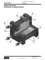
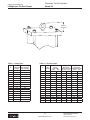
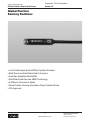
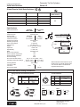
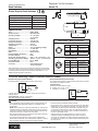
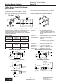
aerospace climate control electromechanical filtration fluid & gas handling hydraulics pneumatics process control sealing & shielding Pneumatic Tie Rod Style Cylinders Series VE for Valve Actuation Catalog HY08-0948-3/NA Pneumatic Tie Rod Cylinders Series VE From new system design to improvements required for existing applications, Parker offers unparalleled engineering expertise. We’ll help you develop cost saving, high performance solutions that provide value through increased productivity, improved machine efficiency, and reduced downtime. With annual sales exceeding $10 billion, Parker Hannifin is the world’s leading diversified manufacturer of motion and control technologies and systems, providing precisionengineered solutions for a wide variety of mobile, industrial and aerospace markets. The company employs approximately 52,000 people in 48 countries around the world. Parker has increased its annual dividends paid to shareholders for 53 consecutive years, among the top five longest-running dividend-increase records in the S&P 500 index. For more information, visit the company’s web site at http://www.parker. com, or its investor information site at http://www.phstock.com. Parker is Engineering Fluid Power and application expertise provide customers the opportunity to use us as an extension of their design teams. Worldwide Supplier to Industrial Markets Parker Hannifin is the world’s leading supplier of motion and control technologies that include; motion control products, systems, and complete engineered solutions for industrial markets. Parker's broad and extensive breadth of product Our design engineers utilize the highest quality materials and cutting edge manufacturing processes available to push the envelope for performance, value and reliability. Parker components and systems are made to last. We offer complete system solutions for the following industries: •Plastics •Metal Forming •Steel •Press •Off Shore Oil •Forestry •Mining •Entertainment •Flight Simulation •Fatigue Testing •Automation www.parker.com/cylinder offer single source capability with limitless possibilities. Our Industrial product solutions range from state of the art stand-alone components to complete engineered systems that are designed to provide value and efficiency to all of our customers. Each component and system is backed up with superior application expertise and technical support that you would expect from Parker Hannifin. Parker Hannifin Corporation Cylinder Division Des Plaines, Illinois USA Catalog HY08-M0948-3/NA Table of Contents Pneumatic Tie Rod Cylinders Series VE Table of Contents Cylinder Features 2 Standard Specifications 4 Cylinder Weights 4 Model Numbers – How to Develop Them and Decode Them 5 TB Mount Dimensions 2.00" Through 2.50" Bore 6 3.25" Through 8.00" Bore 7 10.00" Through 24.00" Bore 8 JB Mount Dimensions 7.00" Through 20.00" Bore 9 Lifting Eyes 10 Tie Rod Torque 10 Position Indicating Switches 11 Solid State Switches 12 Reed Switch 13 Mounting Brackets 14 Switch Cord Sets 14 Cylinder Safety Guide 15 Offer of Sale 17 1 www.millerfluidpower.com Miller Fluid Power Cylinder Division Des Plaines, Illinois USA Pneumatic Tie Rod Cylinders Series VE Catalog HY08-0948-3/NA Cylinder Features Parker Series VE Pneumatic Tie Rod Cylinders 7 8 4 5 9 1 6 3 2 2 www.parker.com/cylinder Parker Hannifin Corporation Cylinder Division Des Plaines, Illinois USA Pneumatic Tie Rod Cylinders Series VE Catalog HY08-0948-3/NA Cylinder Features Parker Series VE Pneumatic Tie Rod Cylinders Features Description “Jewel” Rod Gland Assembly is externally 1 removable without disassembling the cylinder. The “Jewel” rod gland incorporates a primary and secondary seal to assure leak-free service and longevity. The secondary seal acts as a rod wiper to prevent contamination from entering the cylinder. In addition, the secondary seal acts as a back up in the event of primary seal failure. All tie rods are made from high strength 100,000 5 psi minimum yield material. Align-A-Groove design provides a 3/16" wide 6 surface machined at each end of the cylinder body to assure tube to head alignment and leak free operation. All piston rod assemblies utilize induction case 2 hardened, medium carbon steel. All piston rods are hard chrome plated and polished to a 10 RMS surface finish. Each piston rod assembly comes standard with two wrench flats to facilitate rod end attachment. NPT ports are standard throughout the entire 7 bore range. Magnetic piston sensing option relays piston 8 position throughout the entire stroke range. Solid state or reed switches are available with quick disconnect or flying lead terminations. This option is available on all bore sizes. Note: Wear band supplied with magnetic piston only. Wear compensating lip seals are used 3 throughout the rod gland and piston assembly to assure leak free operation and optimal performance over the life of the cylinder. Heads and caps are made from heavy duty steel 9 and are machined to provide concentricity. Cylinder body material options include steel with 4 chrome plated I.D., aluminum, and composite to suit demanding application requirements. The Series VE cylinder provides OEM’s and End Users a durable yet cost effective solution for knife gate valve actuation. Innovative options offer the ability to sense piston rod position, reduce weight, and increase corrosion resistance – resulting in improved system efficiency and reduced maintenance costs. Parker’s utilization of cutting edge design systems, proven seal technology, the highest quality materials, and stringent quality standards assure reliable service in the most demanding applications. 3 www.parker.com/cylinder Parker Hannifin Corporation Cylinder Division Des Plaines, Illinois USA Pneumatic Tie Rod Cylinders Series VE Catalog HY08-0948-3/NA Standard Specifications Standard Specifications • Single and Double Piston Rod Construction Available • Spring Extend or Retract • Double Acting • Bore Diameters – 2.00" to 24.00" • Maximum Working Pressure – 150 PSI Pneumatic •Piston Rod Diameters – .625" to 3.500" •Stroke Lengths – Bore Diameter Dependant In line with our policy of continuing product improvement, specifications in this catalog are subject to change. Seal Class Table Seal Classes Typical Fluids Temperature Range 1 - Standard Nitrile Compressed Air (pneumatic) -10°F (-23°C) to +165°F (+74°C) 4 - Optional (at extra cost) Low Temp Nitrile Seals Compressed Air (pneumatic) Low Temperature -50°F (-46°C) to +150°F (+66°C) Compressed Air (pneumatic) High Temperature -10°F (-23°C) to + 250°F (+121°C) 1 5 - Optional (at extra cost) Fluorocarbon Seals 1 Class 5 Seals are limited to bore diameters up to 14.00". Cylinder Weight Chart Bore Ø Rod Ø 2.00 2.50 3.25 4.00 5.00 6.00 7.00 8.00 10.00 12.00 14.00 16.00 18.00 20.00 22.00 24.00 0.625 0.625 1.000 1.000 1.000 1.000 1.000 1.000 1.000 1.375 1.375 1.750 2.000 2.000 3.000 3.500 Weight at Zero Weight per in Weight at Zero Weight per Weight at Zero Weight per Stroke with Steel Stroke w/ Steel Stroke with in Stroke w/ Stroke with in Stroke w/ Tube & Cast Iron Tube & Cast Iron Aluminum Tube Aluminum Tube Composite Tube Composite Tube Piston (lbs.) Piston (lbs.) & Aluminum & Aluminum & Cast Iron & Cast Iron Piston (lbs.) Piston (lbs.) Piston (lbs.) Piston (lbs.) 6.50 9.00 12.97 17.10 27.45 37.24 51.50 66.17 125.56 181.23 277.02 384.26 526.85 668.35 899.78 1295.20 0.50 0.60 0.70 0.87 1.09 1.40 1.71 2.13 2.63 3.16 3.70 6.09 7.09 7.91 12.10 14.99 6.00 8.50 10.78 13.75 21.25 29.11 39.8 50.65 - Cylinder Weight Chart Bore Ø Rod Ø 2.00 2.50 3.25 4.00 5.00 6.00 7.00 8.00 10.00 12.00 14.00 16.00 18.00 20.00 22.00 24.00 0.625 0.625 1.000 1.000 1.000 1.000 1.000 1.000 1.000 1.375 1.375 1.750 2.000 2.000 3.000 3.500 0.40 0.50 0.47 0.50 0.63 0.67 0.97 1.00 - 0.43 0.45 0.57 0.60 0.75 0.78 1.18 1.47 1.74 2.55 3.11 3.51 5.20 6.08 Weight Adder Double Rod Cylinders Weight at Zero Stroke Weight per in Stroke with Composite Tube & w/ Composite Tube & Aluminum Piston (lbs.) Aluminum Piston (lbs.) 10.73 13.69 21.26 29.02 39.47 50.32 99.82 143.4 224.19 303.44 412.92 513.34 698.71 1031.15 12.63 16.57 26.66 36.15 50.06 64.15 123.22 178.39 273.58 377.17 517.89 657.34 881.66 1269.61 0.43 0.45 0.57 0.6 0.75 0.78 1.18 1.47 1.74 2.55 3.11 3.51 5.20 6.08 4 www.parker.com/cylinder Bore Ø Rod Ø 0" Stroke Per Inch Adder 2.00 2.50 3.25 4.00 5.00 6.00 7.00 8.00 10.00 12.00 14.00 16.00 18.00 20.00 22.00 24.00 0.625 0.625 1.000 1.000 1.000 1.000 1.000 1.000 1.000 1.375 1.375 1.750 2.000 2.000 3.000 3.500 0.10 0.10 0.17 0.17 0.17 0.19 0.19 0.19 0.22 0.42 0.42 0.85 1.33 1.33 4.50 6.12 0.22 0.22 0.22 0.22 0.22 0.22 0.22 0.22 0.22 0.42 0.42 0.68 0.89 0.89 2.00 2.72 Parker Hannifin Corporation Cylinder Division Des Plaines, Illinois USA Pneumatic Tie Rod Cylinders Series VE Catalog HY08-0948-3/NA How To Order How to Order Series VE Air Cylinders for Valve Actuation How to Order Code K 5.00 TB E Double Mounting Mounting Rod Style Modification Bore Dia. Use "K" for Double rod cylinders only. Leave blank if not required Specify bore dia. in inches: 2.00 2.50 3.25 4.00 5.00 6.00 7.00 8.00 10.00 12.00 14.00 16.00 18.00 20.00 22.00 24.00 VE Series Piston1 U V Ports S Common Special Modifi- Modifications cations U = NPT Ports (Dry Seal Type) Specify E for cap welded lifting eye. (only if required) Specify Mounting Style TB (Tie Rods Ext. Head) JB3 (Head Square Flange Mounting) L 1 A Piston Piston Piston Rod Rod Rod End Thread Number Specify Rod Number 1 VE L = Non Magnetic Piston, Steel Tube P 6 = Non Magnetic Piston, Composite Tube A = Magnetic Piston, Aluminum Tube 3 6 = Magnetic Piston, Composite Tube 9 If Required Specify V5 = Fluorocarbon Seals 4 = Low Temp Seals 24.000 Stroke 2 A = UNF Select: Style 9 Female Style 8 Intermediate Male Style 4 Small Male Style 3 4 (Special) Specify in inches. Use only if special modifications are required: Port Position Change Special Seals Stop Tube2 Stroke Adjusters Available Special Options • Stainless Steel Piston Rods • Spring Extend or Retract • Double Rod End Style • High Temperature Seals • Water Service – consult factory for applications above 100°F (38°C) • Lifting Eyes (welded on cap face) • Stroke Adjuster (infrequent) • Tie Rods Extended Head and Cap (Consult Factory) • Low Temperature Nitrile Seals Shaded boxes identify required model number fields. Lipseal Piston is Standard for all piston options. The following lists standard tube and optional tube materials by bore diameter range with available piston codes: L - Steel Tube is Standard for 2.00" - 8.00" bore (Non Magnetic Piston); Optional at extra cost 10.00" - 24.00" P - Composite Tube is Optional for 3.25" - 8.00" (Non Magnetic Piston); Standard 10.00" - 24.00" A - Aluminum Tube is Standard for 2.00" - 8.00" (Magnetic Piston); not available 10.00" - 24.00" 3 - Composite Tube is Optional for 3.25" - 8.00" (Magnetic Piston); Standard 10.00" - 24.00" 1 If stop tube is required, please provide gross stroke length (gross stroke = stop tube + net stroke). JB Mount is available in bore diameters 7.00" through 20.00" only. 4 Style #3 Rod End is deemed a “special”. When ordering, please supply KK, A and W Dimensions. 5 Class 5 Seals are limited to bore diameters up to 14.00". 6 Composite tubing is not to be exposed to fluids which have a pH level lower than 3 or higher than 11. 2 3 5 www.parker.com/cylinder Parker Hannifin Corporation Cylinder Division Des Plaines, Illinois USA Pneumatic Tie Rod Cylinders TB Mount Dimensions – 2.00" to 2.50" bore Series VE Catalog HY08-0948-3/NA Cylinder Dimensions 2.00" - 2.50" W E R LB + STROKE Y DD P + STROKE EE ØMM E R BB LA A KK LA W A CC ØB NA ØMM D WRENCH FLATS J G A W Style 4 – Small Male ØMM ØB NA ØMM D WRENCH FLATS V D WRENCH FLATS W KK ØB NA V K1 Style 8 – Intermediate Male V Style 9 – Female Cylinder Dimensional Table Bore Ø MM Rod Ø BB DD E EE (NPTF) G J K1 R Y Add Stroke Max Stroke LB P 2.00 0.625 1.13 5/16-24 2.50 1/4 1.88 1.00 0.44 1.84 1.94 4.00 2.25 60" 2.50 0.625 1.13 5/16-24 3.00 1/4 1.88 1.00 0.44 2.19 1.94 4.13 2.38 50" Rod End Dimensional Table Bore Ø MM Rod Ø Style 4 KK Style 8 CC Style 9 KK A BØ +.000 -.002 D LA NA V W 2.00 0.625 7/16-20 1/2-20 7/16-20 0.75 1.124 0.50 1.38 0.56 0.25 0.63 2.50 0.625 7/16-20 1/2-20 7/16-20 0.75 1.124 0.50 1.38 0.56 0.25 0.63 6 www.parker.com/cylinder Parker Hannifin Corporation Cylinder Division Des Plaines, Illinois USA Pneumatic Tie Rod Cylinders TB Mount Dimensions – 3.25" to 8.00" bore Series VE Catalog HY08-0948-3/NA Cylinder Dimensions 3.25" - 8.00" E R W Y DD E R ØMM BB LA A KK A CC ØB NA ØMM D WRENCH FLATS G LA W W W KK ØMM ØB NA ØMM D WRENCH FLATS V D WRENCH FLATS Style 4 – Small Male J A ØB NA V K1 LB + STROKE P + STROKE EE Style 8 – Intermediate Male V Style 9 – Female Cylinder Dimensional Table Bore Ø MM Rod Ø BB DD E EE (NPTF) G J K1 R Y Add Stroke Max Stroke LB P 3.25 1.000 1.38 3/8-24 4.00 1/4 1.00 1.00 0.50 2.76 1.19 3.25 2.38 4.00 1.000 1.38 3/8-24 4.50 3/8 1.00 1.00 0.50 3.32 1.19 3.25 2.38 80" 5.00 1.000 1.81 1/2-20 5.50 3/8 1.00 1.00 0.63 4.10 1.19 3.50 2.63 65" 100" 6.00 1.000 1.81 1/2-20 6.50 3/8 1.00 1.00 0.63 4.88 1.31 3.38 2.50 55" 7.00 1.000 2.00 5/8-18 7.50 3/8 1.00 1.00 0.75 5.73 1.31 3.50 2.63 45" 8.00 1.000 2.00 5/8-18 8.50 3/8 1.00 1.00 0.75 6.44 1.31 3.50 2.63 40" Rod End Dimensional Table Bore Ø MM Rod Ø Style 4 KK Style 8 CC Style 9 KK A BØ +.000 -.002 D LA NA V W 3.25 1.000 3/4-16 7/8-14 3/4-16 1.13 1.499 0.88 1.88 0.94 0.31 0.75 4.00 1.000 3/4-16 7/8-14 3/4-16 1.13 1.499 0.88 1.88 0.94 0.31 0.75 5.00 1.000 3/4-16 7/8-14 3/4-16 1.13 1.499 0.88 1.88 0.94 0.31 0.75 6.00 1.000 3/4-16 7/8-14 3/4-16 1.13 1.499 0.88 2.00 0.94 0.38 0.88 7.00 1.000 3/4-16 7/8-14 3/4-16 1.13 1.499 0.88 2.00 0.94 0.38 0.88 8.00 1.000 3/4-16 7/8-14 3/4-16 1.13 1.499 0.88 2.00 0.94 0.38 0.88 7 www.parker.com/cylinder Parker Hannifin Corporation Cylinder Division Des Plaines, Illinois USA Pneumatic Tie Rod Cylinders Series VE Catalog HY08-0948-3/NA TB Mount Dimensions – 10.00" to 24.00" Cylinder Dimensions 10.00" - 24.00" E R E W LB + STROKE Y P + STROKE EE DD R ØMM BB LA A KK ØB NA ØMM D WRENCH FLATS A A CC W Style 4 – Small Male ØMM ØB NA ØMM D WRENCH FLATS V D WRENCH FLATS W KK ØB NA V J G LA W K1 Style 8 – Intermediate Male V Style 9 – Female Cylinder Dimensional Table Bore Ø MM Rod Ø BB 10.00 1.000 2.25 DD 3/4-16 E 10.63 EE (NPTF) G 1/2 1.31 J 1.31 K1 0.88 R 7.92 Y 1.56 Add Stroke LB P 4.25 3.13 Max Stroke 30" 12.00 1.375 2.25 3/4-16 12.75 1/2 1.31 1.31 0.88 9.40 1.56 4.31 3.19 50" 14.00 1.375 2.50 7/8-14 14.75 3/4 1.56 1.56 1.00 10.90 1.69 4.88 3.50 40" 16.00 1.750 2.75 1-14 17.00 3/4 1.56 1.56 1.13 12.59 1.94 5.13 3.75 60" 18.00 2.000 3.25 1 1/8-12 19.00 3/4 1.69 1.69 1.25 14.14 2.19 5.63 4.25 70" 20.00 2.000 3.25 1 1/4-12 21.00 3/4 1.69 1.69 1.38 15.77 2.19 5.88 4.50 65" 22.00 3.000 3.50 1 1/4-12 23.00 3/4 1.94 1.94 1.38 17.18 3.06 6.50 4.88 60" 24.00 3.500 3.50 1 1/4-12 25.25 3/4 2.44 2.44 1.38 18.74 3.56 7.75 5.13 60" Style 8 CC Style 9 KK A BØ +.000 -.002 D LA NA V W Rod End Dimensional Table Bore Ø MM Rod Ø Style 4 KK 10.00 1.000 3/4-16 7/8-14 3/4-16 1.13 1.499 0.88 2.13 0.94 0.38 1.00 12.00 1.375 1-14 1 1/4-12 1-14 1.63 1.999 1.13 2.63 1.31 0.38 1.00 14.00 1.375 1-14 1 1/4-12 1-14 1.63 1.999 1.13 2.63 1.31 0.38 1.00 16.00 1.750 1 1/4-12 1 1/2-12 1-14 1.63 2.374 1.50 2.88 1.69 0.50 1.25 18.00 2.000 1 1/2-12 1 3/4-12 1 1/2-12 2.25 2.624 1.69 3.75 1.94 0.56 1.50 20.00 2.000 1 1/2-12 1 3/4-12 1 1/2-12 2.25 2.624 1.69 3.75 1.94 0.56 1.50 22.00 3.000 2 1/4-12 2 3/4-12 2 1/4-12 3.50 3.749 2.63 5.75 2.88 0.63 2.25 24.00 3.500 2 1/2-12 3 1/4-12 2 1/2-12 3.50 4.249 3.00 5.75 3.38 0.63 2.25 8 www.parker.com/cylinder Parker Hannifin Corporation Cylinder Division Des Plaines, Illinois USA Pneumatic Tie Rod Cylinders Series VE Catalog HY08-0948-3/NA JB Mount Dimensions – 7.00" to 20.00" Cylinder Dimensions 7.00" - 20.00" E R E TE A P + STROKE A CC ØB NA ØMM W W KK ØMM ØMM ØB NA D WRENCH FLATS V D WRENCH FLATS Style 4 – Small Male J G A ØB NA V K1 ØMM LA W D WRENCH FLATS Y EB Ø 4 HOLES TE KK LB + STROKE EE R LA W Style 8 – Intermediate Male V Style 9 – Female Cylinder Dimensional Table Bore Ø MM Rod Ø E 7.00 1.000 7.50 EB 0.56 EE (NPTF) G 3/8 1.00 J K1 1.00 0.75 R 5.73 TE 6.75 Y 1.31 LB Add Stroke P Max Stroke 3.50 2.63 45" 8.00 1.000 8.50 0.69 3/8 1.00 1.00 0.75 6.44 7.57 1.31 3.50 2.63 40" 10.00 1.000 10.63 0.81 1/2 1.31 1.31 0.88 7.92 9.40 1.56 4.25 3.13 30" 12.00 1.375 12.75 0.81 1/2 1.31 1.31 0.88 9.40 11.10 1.56 4.31 3.19 50" 14.00 1.375 14.75 0.94 3/4 1.56 1.56 1.00 10.90 12.87 1.69 4.88 3.50 40" 16.00 1.750 17.00 1.06 3/4 1.56 1.56 1.13 12.59 14.85 1.94 5.13 3.75 60" 18.00 2.000 19.00 1.19 3/4 1.69 1.69 1.25 14.14 16.69 2.19 5.63 4.25 70" 20.00 2.000 21.00 1.31 3/4 1.69 1.69 1.38 15.77 18.46 2.19 5.88 4.50 65" Rod End Dimensional Table Bore Ø MM Rod Ø Style 4 KK Style 8 CC Style 9 KK A BØ +.000 -.002 D LA NA V W 7.00 1.000 3/4-16 7/8-14 3/4-16 1.13 1.499 0.88 2.00 0.94 0.38 0.88 8.00 1.000 3/4-16 7/8-14 3/4-16 1.13 1.499 0.88 2.00 0.94 0.38 0.88 10.00 1.000 3/4-16 7/8-14 3/4-16 1.13 1.499 0.88 2.13 0.94 0.38 1.00 12.00 1.375 1-14 1 1/4-12 1-14 1.63 1.999 1.13 2.63 1.31 0.38 1.00 14.00 1.375 1-14 1 1/4-12 1-14 1.63 1.999 1.13 2.63 1.31 0.38 1.00 16.00 1.750 1 1/4-12 1 1/2-12 1-14 1.63 2.374 1.50 2.88 1.69 0.50 1.25 18.00 2.000 1 1/2-12 1 3/4-12 1 1/2-12 2.25 2.624 1.69 3.75 1.94 0.56 1.50 20.00 2.000 1 1/2-12 1 3/4-12 1 1/2-12 2.25 2.624 1.69 3.75 1.94 0.56 1.50 9 www.parker.com/cylinder Parker Hannifin Corporation Cylinder Division Des Plaines, Illinois USA Pneumatic Tie Rod Cylinders Series VE Catalog HY08-0948-3/NA Lifting Eyes / Tie Rod Torque HEIGHT (WELDED) Table 1 – Lifting Eyes Table 2 – Tie Rod Torque Bore Ø Welded Lifting Eye Height Welded Lifting Eye Capacity (lbs. per eye) 2.00 1.63 500 2.50 1.63 500 3.25 3.19 2000 4.00 3.19 2000 5.00 3.19 4000 6.00 3.19 4000 7.00 3.19 4000 8.00 3.19 4000 10.00 3.19 4000 12.00 3.19 4000 14.00 3.19 4000 16.00 3.19 4000 18.00 3.19 4000 20.00 3.19 4000 22.00 3.19 4000 24.00 3.19 4000 Bore Ø Tie Rod Size (inches) Tie Rod Nut Torque Steel Tube ft. lbs. N-m Tie Rod Nut Torque Aluminum Tube ft. lbs. N-m Tie Rod Nut Torque Composite Tube ft. lbs. N-m 2.00 5/16-24 12 16 6 8 - 2.50 5/16-24 12 16 6 8 - - 3.25 3/8-24 25 34 18 24 13 17 4.00 3/8-24 25 34 18 24 13 17 5.00 1/2-20 60 81 37 50 30 41 6.00 1/2-20 60 81 37 50 30 41 7.00 5/8-18 90 122 60 81 55 75 8.00 5/8-18 110 149 60 81 55 75 - 10.00 3/4-16 148 201 - - 78 106 12.00 3/4-16 172 233 - - 78 106 14.00 7/8-14 275 373 - - 118 160 16.00 1-14 390 529 - - 250 339 18.00 1 1/8-12 540 732 - - 350 475 20.00 1 1/4-12 745 1010 - - 450 610 22.00 1 1/4-12 745 1010 - - 500 678 24.00 1 1/4-12 745 1010 - - 500 678 10 www.parker.com/cylinder Parker Hannifin Corporation Cylinder Division Des Plaines, Illinois USA Catalog HY08-0948-3/NA Global Position Sensing Switches Pneumatic Tie Rod Cylinders Series VE Global Position Sensing Switches • Low Profile Keeps Switch Within Cylinder Envelope • Both Reed and Solid State Switch Versions • Switches Available World-Wide • Solid State Switches use GMR Technology • 5 Different Connection Styles • Allow Position Sensing Anywhere Along Cylinder Stroke • CE Approved 11 www.parker.com/cylinder Parker Hannifin Corporation Cylinder Division Des Plaines, Illinois USA Pneumatic Tie Rod Cylinders Series VE Catalog HY08-0948-3/NA Solid State Switches Global Drop-In Solid State Switches Wiring 3m Flying Leads NPN Switch PNP Switch ATEX Certified P8S-GPFLX P8S-GNFLX P8S-GPFLX/EX1 10m Flying Leads P8S-GPFTX P8S-GNFTX 0.3m Lead with 8mm Connector P8S-GPSHX P8S-GNSHX 0.3m Lead with 12mm Connector P8S-GPMHX P8S-GNMHX 1m Lead with 8mm Connector P8S-GPSCX P8S-GNSCX N/A ATEX switch is supplied with 2m Flying Leads. Specifications Switch Classification Type Output Function Switch Output Operating Voltage Continuous Current Response Sensitivity Switching Frequency Power Consumption Voltage Drop Ripple Hysteresis Repeatability EMC Short-circuit Protection Power-up Pulse Suppression Reverse Polarity Protection Enclosure Rating Shock and Vibration Stress Operating Temperature Range Housing Material Connector Cable Connector Approval for ATEX Standard ATEX Certified PNP or NPN PNP Electronic Normally Open PNP/NPN PNP 10 - 30VDC 18 - 30VDC 100 mA max. 70 mA max. 28 Gauss min. 1kHz 10 mA max. 2.5 VDC max. 10% of Operating Voltage 1.5 mm max. 0.1 mm max. EN 60 947-5-2 Yes Yes Yes IP68 30g, 11 ms,10 to 55Hz, 1 mm -25°C to +75°C -20°C to +45°C (-13°F to +167°F) (-4°F to +113°F) PA 12 Black PVC PUR – – 3D/3G 4.3 Sensing Face Center 6.1 9.7 31.5 L = 300 M8x1 1 PNP Switch 36 Global solid state switch outputs may be influenced by an external magnetic field. Care must be taken to avoid external magnetic field exposure. Solid State Switch Wiring Connection Flying Lead or 8 mm Connector (shown) 4 1 3 Pin Wire 1 Brown 4 Black 3 Blue 12 mm Connector Function Operating Voltage (+VDC) Output signal (N.O.) -VDC 21 3 4 1 PNP 1 NPN bn +VDC 1 bn 1 LOAD bk 4 bk 4 LOAD 3 bu -VDC 3 bu Wire 1 Brown 4 21 3 Black White Blue Function Operating Voltage (+VDC) Output Signal (N.O.) Not Used -VDC Pin 2 not present. PNP +VDC Pin bn 1 bk 4 bu 3 NPN + DC – bn 1 bk 4 bu 3 + DC – -VDC 12 www.parker.com/cylinder Parker Hannifin Corporation Cylinder Division Des Plaines, Illinois USA Pneumatic Tie Rod Cylinders Series VE Catalog HY08-0948-3/NA Reed Switches Global Drop-In Reed Switches Wiring 4.3 Reed Switch 3m Flying Leads P8S-GRFLX 10m Flying Leads P8S-GRFTX 0.3m Lead with 8mm Connector P8S-GRSHX 0.3m Lead with 12mm Connector P8S-GRMHX 1m Lead with 8mm Connector P8S-GRSCX Sensing Face Center 6.1 14 31.5 L = 300 Type..............................................2-Wire Reed Output Function.............................Normally Open Operating Voltage.........................10 - 120 VAC1 10 - 30 VDC Switching Power............................6 W/VA Continuous Current.......................100 mA max. Response Sensitivity.....................30 Gauss min. Switching Frequency.....................400 Hz Voltage Drop.................................2.5 V max. Ripple............................................10% of Operating Voltage Hysteresis......................................1.5 mm max. Repeatability..................................0.2 mm max. EMC...............................................EN 60 947-5-2 Reverse Polarity Protection...........Yes Enclosure Rating...........................IP 68 Shock and Vibration Stress...........30g, 11 ms, 10 to 55 Hz, 1 mm Operating Temperature Range.....-25°C to +75°C (-13°F to 167°F) Housing Material...........................PA 12, Black Connector Cable...........................PVC Connector......................................PUR cable with 8 or 12 mm connector Global Reed Switch output may be influenced by external magnetic fields. Care must be taken to avoid external magnetic field exposure. See Parker Industrial Cylinder Catalogs and Cylinder Safety Guide 0800.01-T1 for additional product application information. M8x1 Specifications 36 Reed Switch – Wiring Connection Flying Lead or 8 mm Connector1 4 1 1 3 Pin Wire 1 Brown 4 Black 3 Blue Function Operating Voltage (+V) Not Used Output Signal (-V or Ground) 8mm connector rated for 50 VAC max. 12 mm Connector 22 3 2 1 4 Pin 2 not present. Pin Wire 1 Brown 2 White 2 Function Operating Voltage (+V) Not Used 3 Blue Output Signal (-V or Ground) 4 Black Not Used Circuit for Switching Contact Protection (Inductive Loads) (Required for proper operation 24V DC) (Recommended for longer life 125 VAC) Put Diode parallel to loads following polarity as shown below. Put a resistor and capacitor in parallel with the load. Select the resistor and capacitor according to the load. Brown Blue Typical Example: CR: Relay coil (under 2W coil rating) R: Resistor 1 K - 5 K, 1/4 W C: Capacitor 0.1 F, 600 V DC D Load Load R AC D: Diode: select a Diode with the breakdown voltage and current rating according to the load. Brown C Blue Typical Example—100 Volt, 1 Amp Diode CR: Relay coil (under 0.5W coil rating) Caution –Use an ampmeter to test reed switch current. Testing devices such as incandescent light bulbs may subject the reed switch to high in-rush loads. –NOTE: When checking an unpowered reed switch for continuity with a digital ohmmeter the resistance reading will change from infinity to a very large resistance (2 M ohm) when the switch is activated. This is due to the presence of a diode in the reed switch. –Anti-magnetic shielding is recommended for reed switches exposed to high external RF or magnetic fields. –The magnetic field strength of the piston magnet is designed to operate with our switches. Other manufacturers’ switches or sensors may not operate correctly in conjunction with these magnets. –Use relay coils for reed switch contact protection. –The operation of some 120 VAC PLC’s (especially some older AllenBradley PLC’s) can overload the reed switch. The switch may fail to release after the piston magnet has passed. This problem may be corrected by the placement of a 700 to 1K OHM resistor between the switch and the PLC input terminal. Consult the manufacturer of the PLC for appropriate circuit. –Switches with long wire leads (greater than 15 feet) can cause capacitance build-up and sticking will result. Attach a resistor in series with the reed switch (the resistor should be installed as close as possible to the switch). The resistor should be selected such that R (ohms) >E/0.3. 13 www.parker.com/cylinder Parker Hannifin Corporation Cylinder Division Des Plaines, Illinois USA Pneumatic Tie Rod Cylinders Series VE Catalog HY08-0948-3/NA Mounting Bracket / Cordsets Tie Rod Bracket Assembly Part Number and Dimensions facilitate switch mounting. Please note the standard location of this tie rod as depicted below. For alternate locations, please consult factory. Global switches and bracket assembles must be ordered separately. Global switch bracket fits 2.00 "-24.00" bore cylinders. Cylinder bore sizes 2.00" through 12.00" do not incorporate an extra tie rod for switch mounting. Bore sizes 14.00" through 24.00" utilize a fifth tie rod to P8S-TMA0X 35 mm 15.7 mm 2.00" - 12.00" Bore 14.00" - 24.00" Bore 8mm and 12mm Cordset for Global Switches Cordset Specifications A female connector is available for all switches with the male 8mm and 12mm quick connect option. The cordsets are available with a right angle or straight connector. Cordset part numbers are listed below. Connector.....................Oil resistant polyurethane body material, PA 6 (Nylon) contact carrier, spacings to VDE 0110 Group C, (150 AC/DC) Contacts.......................Gold plated beryllium copper, machined from solid stock Coupling Method..........Snap-Lock or chrome plated brass nut Cord Construction .......Oil resistant black PUR jacket, non-wicking, non-hygroscopic, 300V. Cable end is stripped and tinned. Conductors...................Extra high flex stranding, PVC insulation Temperature.................-40 to 194°F (-40 to 90°C) Protection.....................NEMA 1, 3, 4, 6P and IEC 1P67 Cable Length................6.56 ft (2m) or 16.4 ft (5m) 8mm Cordset Threaded Connector Cable Length Snap On Connector 5 meters 086620T005 086620S005 2 meters 086620T002 086620S002 Cable Length Threaded Connector Right Angle Connector 5 meters 9126487205 9126487305 2 meters 9126487202 9126487302 12mm Cordset 8mm Snap-On Straight Connector 8mm Threaded Straight Connector CABLE LENGTH (m) (SEE TABLE) M8x1 CABLE LENGTH (m) (SEE TABLE) Ø .318 8.1 Ø .177 4.5 CABLE MINIMUM BEND RADIUS: 100mm 1.110 28.2 Ø .378 9.6 Ø .177 4.5 Ø .224 5.7 .276 7.0 CABLE MINIMUM BEND RADIUS: 100mm 1.181 30.0 12mm Right Angle Connector 1.26 32.0 12mm Straight Connector PIN 2 / WHT Ø14.5 CABLE LENGTH (m) (SEE TABLE) PIN 3 / BLU 42 PIN 2 / WHT PIN 3 / BLU PIN 1 / BRN PIN 4 / BLK 38.3 1.5 Ø14.5 CABLE MINIMUM BEND RADIUS: 100mm M12 X 1 PIN 4 / BLK CABLE MINIMUM BEND RADIUS: 100mm 26.5 PIN 1 / BRN CABLE LENGTH (SEE TABLE) 1.5 M12 X 1 14 www.parker.com/cylinder Parker Hannifin Corporation Cylinder Division Des Plaines, Illinois USA Pneumatic Tie Rod Cylinders Series VE Catalog HY08-0948-3/NA Cylinder Safety Guide Safety Guide for Selecting and Using Hydraulic, Pneumatic Cylinders and Their Accessories WARNING: Failure of the cylinder, its parts, its mounting, its connections to other objects, or its controls can result in: • Unanticipated or uncontrolled movement of the cylinder or objects connected to it. • Falling of the cylinder or objects held up by it. • Fluid escaping from the cylinder, potentially at high velocity. These events could cause death or personal injury by, for example, persons falling from high locations, being crushed or struck by heavy or fast moving objects, being pushed into dangerous equipment or situations, or slipping on escaped fluid. Before selecting or using Parker Hannifin Corporation (the Company) cylinders or related accessories, it is important that you read, understand and follow the following safety information. Training is advised before selecting and using the Company’s products. 1.0 General Instructions 1.1 Scope – This safety guide provides instructions for selecting and using (including assembling, installing, and maintaining) cylinder products. This safety guide is a supplement to and is to be used with the specific Company publications for the specific cylinder products that are being considered for use. 1.2 Fail Safe – Cylinder products can and do fail without warning for many reasons. All systems and equipment should be designed in a fail-safe mode so that if the failure of a cylinder product occurs people and property won’t be endangered. 1.3 Distribution – Provide a free copy of this safety guide to each person responsible for selecting or using cylinder products. Do not select or use the Company’s cylinders without thoroughly reading and understanding this safety guide as well as the specific Company publications for the products considered or selected. 1.4 User Responsibility – Due to very wide variety of cylinder applications and cylinder operating conditions, the Company does not warrant that any particular cylinder is suitable for any specific application. This safety guide does not analyze all technical parameters that must be considered in selecting a product. The hydraulic and pneumatic cylinders outlined in this catalog are designed to the Company’s design guidelines and do not necessarily meet the design guideline of other agencies such as American Bureau of Shipping, ASME Pressure Vessel Code etc. The user, through its own analysis and testing, is solely responsible for: • Making the final selection of the cylinders and related accessories. • Determining if the cylinders are required to meet specific design requirements as required by the Agency(s) or industry standards covering the design of the user’s equipment. • Assuring that the user’s requirements are met, OSHA requirements are met, and safety guidelines from the applicable agencies such as but not limited to ANSI are followed and that the use presents no health or safety hazards. • Providing all appropriate health and safety warnings on the equipment on which the cylinders are used. 1.5 Additional Questions – Call the appropriate Company technical service department if you have any questions or require any additional information. See the Company publication for the product being considered or used, or call 1-847-298-2400, or go to www.parker.com, for telephone numbers of the appropriate technical service department. • Failure of the pressurized fluid delivery system (hoses, fittings, valves, pumps, compressors) which maintain cylinder position. • Catastrophic cylinder seal failure leading to sudden loss of pressurized fluid. • Failure of the machine control system. Follow the recommendations of the “Piston Rod Selection Chart and Data” in the publication for the series of cylinders of interest. The suggested piston rod diameter in these charts must be followed in order to avoid piston rod buckling. Piston rods are not normally designed to absorb bending moments or loads which are perpendicular to the axis of piston rod motion. These additional loads can cause the piston rod to fail. If these types of additional loads are expected to be imposed on the piston rod, their magnitude should be made known to our engineering department. The cylinder user should always make sure that the piston rod is securely attached to the machine member. On occasion cylinders are ordered with double rods (a piston rod extended from both ends of the cylinder). In some cases a stop is threaded on to one of the piston rods and used as an external stroke adjuster. On occasions spacers are attached to the machine member connected to the piston rod and also used as a stroke adjuster. In both cases the stops will create a pinch point and the user should consider appropriate use of guards. If these external stops are not perpendicular to the mating contact surface, or if debris is trapped between the contact surfaces, a bending moment will be placed on the piston rod, which can lead to piston rod failure. An external stop will also negate the effect of cushioning and will subject the piston rod to impact loading. Those two (2) conditions can cause piston rod failure. Internal stroke adjusters are available with and without cushions. The use of external stroke adjusters should be reviewed with our engineering department. The piston rod to piston and the stud to piston rod threaded connections are secured with an anaerobic adhesive. The strength of the adhesive decreases with increasing temperature. Cylinders which can be exposed to temperatures above +250°F (+121°C) are to be ordered with a non studded piston rod and a pinned piston to rod joint. 2.3 Cushions – Cushions should be considered for cylinder applications when the piston velocity is expected to be over 4 inches/second. Cylinder cushions are normally designed to absorb the energy of a linear applied load. A rotating mass has considerably more energy than the same mass moving in a linear mode. Cushioning for a rotating mass application should be review by our engineering department. 2.4 Cylinder Mountings – Some cylinder mounting configurations may have certain limitations such as but not limited to minimum stroke for side or foot mounting cylinders or pressure de-ratings for certain mounts. Carefully review the catalog for these types of restrictions. Always mount cylinders using the largest possible high tensile alloy steel socket head cap screws that can fit in the cylinder mounting holes and torque them to the manufacturer’s recommendations for their size. 2.0 Cylinder and Accessories Selection 2.1 Seals – Part of the process of selecting a cylinder is the selection of seal compounds. Before making this selection, consult the “seal information page(s)” of the publication for the series of cylinders of interest. The application of cylinders may allow fluids such as cutting fluids, wash down fluids etc. to come in contact with the external area of the cylinder. These fluids may attack the piston rod wiper and or the primary seal and must be taken into account when selecting and specifying seal compounds. Dynamic seals will wear. The rate of wear will depend on many operating factors. Wear can be rapid if a cylinder is mis-aligned or if the cylinder has been improperly serviced. The user must take seal wear into consideration in the application of cylinders. 3.0 Cylinder and Accessories Installation and Mounting 3.1 Installation 3.1.1 – Cleanliness is an important consideration, and cylinders are shipped with the ports plugged to protect them from contaminants entering the ports. These plugs should not be removed until the piping is to be installed. Before making the connection to the cylinder ports, piping should be thoroughly cleaned to remove all chips or burrs which might have resulted from threading or flaring operations. 2.2 Piston Rods – Possible consequences of piston rod failure or separation of the piston rod from the piston include, but are not limited to are: • Piston rod and or attached load thrown off at high speed. • High velocity fluid discharge. • Piston rod extending when pressure is applied in the piston retract mode. Piston rods or machine members attached to the piston rod may move suddenly and without warning as a consequence of other conditions occurring to the machine such as, but not limited to: • Unexpected detachment of the machine member from the piston rod. 2.5 Port Fittings – Hydraulic cylinders applied with meter out or deceleration circuits are subject to intensified pressure at piston rod end. The rod end pressure is approximately equal to: operating pressure x effective cap end area effective rod end piston area Contact your connector supplier for the pressure rating of individual connectors. 15 www.parker.com/cylinder Parker Hannifin Corporation Cylinder Division Des Plaines, Illinois USA Pneumatic Tie Rod Cylinders Series VE Catalog HY08-0948-3/NA Cylinder Safety Guide 3.1.2 – Cylinders operating in an environment where air drying materials are present such as fast-drying chemicals, paint, or weld splatter, or other hazardous conditions such as excessive heat, should have shields installed to prevent damage to the piston rod and piston rod seals. 3.1.3 – Proper alignment of the cylinder piston rod and its mating component on the machine should be checked in both the extended and retracted positions. Improper alignment will result in excessive rod gland and/or cylinder bore wear. On fixed mounting cylinders attaching the piston rod while the rod is retracted will help in achieving proper alignment. 3.1.4 – Sometimes it may be necessary to rotate the piston rod in order to thread the piston rod into the machine member. This operation must always be done with zero pressure being applied to either side of the piston. Failure to follow this procedure may result in loosening the piston to rod-threaded connection. In some rare cases the turning of the piston rod may rotate a threaded piston rod gland and loosen it from the cylinder head. Confirm that this condition is not occurring. If it does, re-tighten the piston rod gland firmly against the cylinder head. For double rod cylinders it is also important that when attaching or detaching the piston rod from the machine member that the torque be applied to the piston rod end of the cylinder that is directly attaching to the machine member with the opposite end unrestrained. If the design of the machine is such that only the rod end of the cylinder opposite to where the rod attaches to the machine member can be rotated, consult the factory for further instructions. 3.2.2 – Side-Mounted Cylinders – In addition to the mounting bolts, cylinders of this type should be equipped with thrust keys or dowel pins located so as to resist the major load. 3.2.3 – Tie Rod Mounting – Cylinders with tie rod mountings are recommended for applications where mounting space is limited. The standard tie rod extension is shown as BB in dimension tables. Longer or shorter extensions can be supplied. Nuts used for this mounting style should be torqued to the same value as the tie rods for that bore size. 3.2.4 – Flange Mount Cylinders – The controlled diameter of the rod gland extension on head end flange mount cylinders can be used as a pilot to locate the cylinders in relation to the machine. After alignment has been obtained, the flanges may be drilled for pins or dowels to prevent shifting. 3.2.5 – Trunnion Mountings – Cylinders require lubricated bearing blocks with minimum bearing clearances. Bearing blocks should be carefully aligned and rigidly mounted so the trunnions will not be subjected to bending moments. The rod end should also be pivoted with the pivot pin in line and parallel to axis of the trunnion pins. 3.2.6 – Clevis Mountings – Cylinders should be pivoted at both ends with centerline of pins parallel to each other. After cylinder is mounted, be sure to check to assure that the cylinder is free to swing through its working arc without interference from other machine parts. 4.1.5 – When cylinders are mounted on equipment that is stored outside for extended periods, exposed unpainted surfaces, e.g. piston rod, must be coated with a rust-inhibiting compound to prevent corrosion. Rod seal leakage could also be traced to gland wear. If clearance is excessive, replace rod bushing and seal. Rod seal leakage can also be traced to seal deterioration. If seals are soft or gummy or brittle, check compatibility of seal material with lubricant used if air cylinder, or operating fluid if hydraulic cylinder. Replace with seal material, which is compatible with these fluids. If the seals are hard or have lost elasticity, it is usually due to exposure to temperatures in excess of 165°F. (+74°C). Shield the cylinder from the heat source to limit temperature to 350°F. (+177°C.) and replace with fluorocarbon seals. 4.2.1.2 – Cylinder body seal leak can generally be traced to loose tie rods. Torque the tie rods to manufacturer’s recommendation for that bore size. Excessive pressure can also result in cylinder body seal leak. Determine maximum pressure to rated limits. Replace seals and retorque tie rods as in paragraph above. Excessive pressure can also result in cylinder body seal leak. Determine if the pressure rating of the cylinder has been exceeded. If so, bring the operating pressure down to the rating of the cylinder and have the tie rods replaced. Pinched or extruded cylinder body seal will also result in a leak. Replace cylinder body seal and retorque as in paragraph above. Cylinder body seal leakage due to loss of radial squeeze which shows up in the form of flat spots or due to wear on the O.D. or I.D. – Either of these are symptoms of normal wear due to high cycle rate or length of service. Replace seals as per paragraph above. 4.2.2 – Internal Leakage 4.2.2.1 – Piston seal leak (by-pass) 1 to 3 cubic inches per minute leakage is considered normal for piston ring construction. Virtually no static leak with lipseal type seals on piston should be expected. Piston seal wear is a usual cause of piston seal leakage. Replace seals as required. 4.2.2.2 – With lipseal type piston seals excessive back pressure due to over-adjustment of speed control valves could be a direct cause of rapid seal wear. Contamination in a hydraulic system can result in a scored cylinder bore, resulting in rapid seal wear. In either case, replace piston seals as required. 4.2.2.3 – What appears to be piston seal leak, evidenced by the fact that the cylinder drifts, is not always traceable to the piston. To make sure, it is suggested that one side of the cylinder piston be pressurized and the fluid line at the opposite port be disconnected. Observe leakage. If none is evident, seek the cause of cylinder drift in other component parts in the circuit. 4.2.3 – Cylinder Fails to Move the Load 4.0 Cylinder and Accessories Maintenance, Troubleshooting and Replacement 4.1 Storage – At times cylinders are delivered before a customer is ready to install them and must be stored for a period of time. When storage is required the following procedures are recommended. 4.1.1 – Store the cylinders in an indoor area which has a dry, clean and noncorrosive atmosphere. Take care to protect the cylinder from both internal corrosion and external damage. 4.1.2 – Whenever possible cylinders should be stored in a vertical position (piston rod up). This will minimize corrosion due to possible condensation which could occur inside the cylinder. This will also minimize seal damage. 4.1.3 – Port protector plugs should be left in the cylinder until the time of installation. 4.1.4 – If a cylinder is stored full of hydraulic fluid, expansion of the fluid due to temperature changes must be considered. Installing a check valve with free flow out of the cylinder is one method. 3.2 Mounting Recommendations 3.2.1 – Always mount cylinders using the largest possible high tensile alloy steel socket head screws that can fit in the cylinder mounting holes and torque them to the manufacturer’s recommendations for their size. 4.2.3.1 – Pneumatic or hydraulic pressure is too low. Check the pressure at the cylinder to make sure it is to circuit requirements. 4.2.3.2 – Piston Seal Leak – Operate the valve to cycle the cylinder and observe fluid flow at valve exhaust ports at end of cylinder stroke. Replace piston seals if flow is excessive. 4.2.3.3 – Cylinder is undersized for the load – Replace cylinder with one of a larger bore size. 4.3 Erratic or Chatter Operation 4.3.1 – Excessive friction at rod gland or piston bearing due to load misalignment – Correct cylinder-to-load alignment. 4.3.2 – Cylinder sized too close to load requirements – Reduce load or install larger cylinder. 4.3.3 – Erratic operation could be traced to the difference between static and kinetic friction. Install speed control valves to provide a back pressure to control the stroke. 4.2 Cylinder Trouble Shooting 4.4 Cylinder Modifications, Repairs, or Failed Component – Cylinders as shipped from the factory are not to be disassembled and or modified. If cylinders require modifications, these modifications must be done at company locations or by the Company’s certified facilities. The Cylinder Division Engineering Department must be notified in the event of a mechanical fracture or permanent deformation of any cylinder component (excluding seals). This includes a broken piston rod, tie rod, mounting accessory or any other cylinder component. The notification should include all operation and application details. This information will be used to provide an engineered repair that will prevent recurrence of the failure. It is allowed to disassemble cylinders for the purpose of replacing seals or seal assemblies. However, this work must be done by strictly following all the instructions provided with the seal kits. 4.2.1 – External Leakage 4.2.1.1 – Rod seal leakage can generally be traced to worn or damaged seals. Examine the piston rod for dents, gouges or score marks, and replace piston rod if surface is rough. 16 www.parker.com/cylinder Parker Hannifin Corporation Cylinder Division Des Plaines, Illinois USA Catalog HY08-0948-3/NA Offer of Sale Pneumatic Tie Rod Cylinders Series VE Offer of Sale The items described in this document and other documents and descriptions provided by Parker Hannifin Corporation, Hydraulics Group, and its authorized distributors (“Seller”) are hereby offered for sale at prices to be established by Seller. This offer and its acceptance by any customer (“Buyer”) shall be governed by all of the following Terms and Conditions. Buyer’s order for any item described in its document, when communicated to Seller verbally, or in writing, shall constitute acceptance of this offer. All goods or work described will be referred to as “Products”. 1. Terms and Conditions. Seller’s willingness to offer Products, or accept an order for 11. Buyer’s Obligation; Rights of Seller. To secure payment of all sums due or other Products, to or from Buyer is expressly conditioned on Buyer’s assent to these Terms and wise, Seller shall retain a security interest in the goods delivered and this agreement Conditions and to the terms and conditions found on-line at www.parker.com/saleterms/. shall be deemed a Security Agreement under the Uniform Commercial Code. Buyer Seller objects to any contrary or additional term or condition of Buyer’s order or any authorizes Seller as its attorney to execute and file on Buyer’s behalf all documents other document issued by Buyer. Seller deems necessary to perfect its security interest. Seller shall have a security interest in, and lien upon, any property of Buyer in Seller’s possession as security for the 2. Price Adjustments; Payments. Prices stated on the reverse side or preceding payment of any amounts owed to Seller by Buyer. pages of this document are valid for 30 days. After 30 days, Seller may change prices to reflect any increase in its costs resulting from state, federal or local legislation, price 12. Improper Use and Indemnity. Buyer shall indemnify, defend, and hold Seller increases from its suppliers, or any change in the rate, charge, or classification of any harmless from any claim, liability, damages, lawsuits, and costs (including attorney carrier. The prices stated on the reverse or preceding pages of this document do not fees), whether for personal injury, property damage, patent, trademark or copyright include any sales, use, or other taxes unless so stated specifically. Unless otherwise infringement or any other claim, brought by or incurred by Buyer, Buyer’s employees, specified by Seller, all prices are F.O.B. Seller’s facility, and payment is due 30 days from or any other person, arising out of: (a) improper selection, improper application or other the date of invoice. After 30 days, Buyer shall pay interest on any unpaid invoices at the misuse of Products purchased by Buyer from Seller; (b) any act or omission, negligent rate of 1.5% per month or the maximum allowable rate under applicable law. or otherwise, of Buyer; (c) Seller’s use of patterns, plans, drawings, or specifications furnished by Buyer to manufacture Product; or (d) Buyer’s failure to comply with these 3. Delivery Dates; Title and Risk; Shipment. All delivery dates are approximate and terms and conditions. Seller shall not indemnify Buyer under any circumstance except Seller shall not be responsible for any damages resulting from any delay. Regardless as otherwise provided. of the manner of shipment, title to any products and risk of loss or damage shall pass to Buyer upon tender to the carrier at Seller’s facility (i.e., when it’s on the truck, it’s yours). 13. Cancellations and Changes. Orders shall not be subject to cancellation or change Unless otherwise stated, Seller may exercise its judgment in choosing the carrier and by Buyer for any reason, except with Seller’s written consent and upon terms that will means of delivery. No deferment of shipment at Buyers’ request beyond the respective indemnify, defend and hold Seller harmless against all direct, incidental and consequendates indicated will be made except on terms that will indemnify, defend and hold Seller tial loss or damage. Seller may change product features, specifications, designs and harmless against all loss and additional expense. Buyer shall be responsible for any availability with notice to Buyer. additional shipping charges incurred by Seller due to Buyer’s changes in shipping, 14. Limitation on Assignment. Buyer may not assign its rights or obligations under product specifications or in accordance with Section 13, herein. this agreement without the prior written consent of Seller. 4. Warranty. Seller warrants that the Products sold hereunder shall be free from 15. Entire Agreement. This agreement contains the entire agreement between the defects in material or workmanship for a period of eighteen months from the date Buyer and Seller and constitutes the final, complete and exclusive expression of the of delivery to Buyer. The prices charged for Seller’s products are based upon the terms of the agreement. All prior or contemporaneous written or oral agreements or exclusive limited warranty stated above, and upon the following disclaimer: negotiations with respect to the subject matter are herein merged. DISCLAIMER OF WARRANTY: THIS WARRANTY COMPRISES THE SOLE AND 16. Waiver and Severability. Failure to enforce any provision of this agreement will not ENTIRE WARRANTY PERTAINING TO PRODUCTS PROVIDED HEREUNDER. waive that provision nor will any such failure prejudice Seller’s right to enforce that proviSELLER DISCLAIMS ALL OTHER WARRANTIES, EXPRESS AND IMPLIED, sion in the future. Invalidation of any provision of this agreement by legislation or other INCLUDING MERCHANTABILITY AND FITNESS FOR A PARTICULAR PURPOSE. rule of law shall not invalidate any other provision herein. The remaining provisions of 5. Claims; Commencement of Actions. Buyer shall promptly inspect all Products this agreement will remain in full force and effect. upon delivery. No claims for shortages will be allowed unless reported to the Seller 17. Termination. This agreement may be terminated by Seller for any reason and at within 10 days of delivery. No other claims against Seller will be allowed unless asserted any time by giving Buyer thirty (30) days written notice of termination. In addition, Seller in writing within 60 days after delivery or, in the case of an alleged breach of warranty, may by written notice immediately terminate this agreement for the following: (a) Buyer within 30 days after the date within the warranty period on which the defect is or should commits a breach of any provision of this agreement (b) the appointment of a trustee, have been discovered by Buyer. Any action based upon breach of this agreement or receiver or custodian for all or any part of Buyer’s property (c) the filing of a petition for upon any other claim arising out of this sale (other than an action by Seller for any relief in bankruptcy of the other Party on its own behalf, or by a third party (d) an assignamount due to Seller from Buyer) must be commenced within thirteen months from ment for the benefit of creditors, or (e) the dissolution or liquidation of the Buyer. the date of tender of delivery by Seller or, for a cause of action based upon an alleged 18. Governing Law. This agreement and the sale and delivery of all Products herebreach of warranty, within thirteen months from the date within the warranty period on under shall be deemed to have taken place in and shall be governed and construed which the defect is or should have been discovered by Buyer. in accordance with the laws of the State of Ohio, as applicable to contracts executed 6. LIMITATION OF LIABILITY. UPON NOTIFICATION, SELLER WILL, AT ITS and wholly performed therein and without regard to conflicts of laws principles. Buyer OPTION, REPAIR OR REPLACE A DEFECTIVE PRODUCT, OR REFUND THE irrevocably agrees and consents to the exclusive jurisdiction and venue of the courts PURCHASE PRICE. IN NO EVENT SHALL SELLER BE LIABLE TO BUYER FOR of Cuyahoga County, Ohio with respect to any dispute, controversy or claim arising out ANY SPECIAL, INDIRECT, INCIDENTAL OR CONSEQUENTIAL DAMAGES ARISING of or relating to this agreement. Disputes between the parties shall not be settled by OUT OF, OR AS THE RESULT OF, THE SALE, DELIVERY, NON-DELIVERY, arbitration unless, after a dispute has arisen, both parties expressly agree in writing to SERVICING, USE OR LOSS OF USE OF THE PRODUCTS OR ANY PART THEREOF, arbitrate the dispute. OR FOR ANY CHARGES OR EXPENSES OF ANY NATURE INCURRED WITHOUT 19. Indemnity for Infringement of Intellectual Property Rights. Seller shall have SELLER’S WRITTEN CONSENT, EVEN IF SELLER HAS BEEN NEGLIGENT, no liability for infringement of any patents, trademarks, copyrights, trade dress, trade WHETHER IN CONTRACT, TORT OR OTHER LEGAL THEORY. IN NO EVENT secrets or similar rights except as provided in this Section. Seller will defend and SHALL SELLER’S LIABILITY UNDER ANY CLAIM MADE BY BUYER EXCEED THE indemnify Buyer against allegations of infringement of U.S. patents, U.S. trademarks, PURCHASE PRICE OF THE PRODUCTS. copyrights, trade dress and trade secrets (“Intellectual Property Rights”). Seller will 7. Contingencies. Seller shall not be liable for any default or delay in performance if defend at its expense and will pay the cost of any settlement or damages awarded in an caused by circumstances beyond the reasonable control of Seller. action brought against Buyer based on an allegation that a Product sold pursuant to this 8. User Responsibility. The user, through its own analysis and testing, is solely Agreement infringes the Intellectual Property Rights of a third party. Seller’s obligation responsible for making the final selection of the system and Product and assuring that to defend and indemnify Buyer is contingent on Buyer notifying Seller within ten (10) days all performance, endurance, maintenance, safety and warning requirements of the after Buyer becomes aware of such allegations of infringement, and Seller having sole application are met. The user must analyze all aspects of the application and follow control over the defense of any allegations or actions including all negotiations for settleapplicable industry standards and Product information. If Seller provides Product or ment or compromise. If a Product is subject to a claim that it infringes the Intellectual system options, the user is responsible for determining that such data and specifications Property Rights of a third party, Seller may, at its sole expense and option, procure for are suitable and sufficient for all applications and reasonably foreseeable uses of the Buyer the right to continue using the Product, replace or modify the Product so as to Products or systems. make it noninfringing, or offer to accept return of the Product and return the purchase 9. Loss to Buyer’s Property. Any designs, tools, patterns, materials, drawings, confiprice less a reasonable allowance for depreciation. Notwithstanding the foregoing, dential information or equipment furnished by Buyer or any other items which become Seller shall have no liability for claims of infringement based on information provided by Buyer’s property, may be considered obsolete and may be destroyed by Seller after Buyer, or directed to Products delivered hereunder for which the designs are specified in two consecutive years have elapsed without Buyer placing an order for the items which whole or part by Buyer, or infringements resulting from the modification, combination or are manufactured using such property. Seller shall not be responsible for any loss or use in a system of any Product sold hereunder. The foregoing provisions of this Section damage to such property while it is in Seller’s possession or control. shall constitute Seller’s sole and exclusive liability and Buyer’s sole and exclusive remedy for infringement of Intellectual Property Rights. 10. Special Tooling. A tooling charge may be imposed for any special tooling, including without limitation, dies, fixtures, molds and patterns, acquired to manufacture 20. Taxes. Unless otherwise indicated, all prices and charges are exclusive of excise, Products. Such special tooling shall be and remain Seller’s property notwithstanding sales, use, property, occupational or like taxes which may be imposed by any taxing payment of any charges by Buyer. In no event will Buyer acquire any interest in authority upon the manufacture, sale or delivery of Products. apparatus belonging to Seller which is utilized in the manufacture of the Products, even 21. Equal Opportunity Clause. For the performance of government contracts and if such apparatus has been specially converted or adapted for such manufacture and where dollar value of the Products exceed $10,000, the equal employment opportunity notwithstanding any charges paid by Buyer. Unless otherwise agreed, Seller shall have clauses in Executive Order 11246, VEVRAA, and 41 C.F.R. §§ 60-1.4(a), 60-741.5(a), the right to alter, discard or otherwise dispose of any special tooling or other property in and 60-250.4, are hereby incorporated. its sole discretion at any time. www.parker.com/cylinder Parker Hannifin Corporation Cylinder Division Des Plaines, Illinois USA 09/09 / Catalog HY08-0948-3/NA Parker Hannifin Corporation Cylinder Division 500 South Wolf Road Des Plaines, IL 60016 USA phone (847) 298-2400 fax (800) 892-1008 www.parker.com/cylinder Parker Hannifin Corporation Motion and Control Division 160 Chisholm Drive Milton, ON Canada L9T 3G9 direct (905) 693-3000 fax (905) 876-1958 www.parker.com