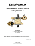
Download Delta Point Lite DeviceNet User Manual
Transcript
DeltaPoint TM Installation and Operation Manual 12 GPM DeviceNet With Drawback Cylinder ROCON LLC 1755 East Nine Mile Road PO Box 249 Hazel Park, MI 48030-0249 TEL (248) 542-9635 FAX (248) 398-4274 Website: http://www.RoconLLC.com TABLE OF CONTENTS PROPRIETARY NOTICE .......................................................................................................................... 3 NAMEPLATE EXAMPLE .......................................................................................................................... 3 SPECIFICATIONS – 12 GPM (45 LPM) UNIT.......................................................................................... 4 PRESSURE DROP DATA ........................................................................................................................ 4 UNIT FRONT VIEW .................................................................................................................................. 5 UNIT SIDE VIEW ...................................................................................................................................... 6 ELECTRICAL CONNECTORS ................................................................................................................. 7 DEVICENET SETUP ................................................................................................................................. 7 Setting MAC ID and Baud Rate ............................................................................................................. 7 Typical Baud Rate Settings ................................................................................................................... 8 MAC ID .................................................................................................................................................. 8 HOW THE DELTAPOINT MONITORS COOLING WATER IN THE ROBOTICS CELL .......................... 9 INSTALLATION .......................................................................................................................................10 NORMAL START UP SEQUENCE .........................................................................................................11 What Happens When a Fault is Detected ...............................................................................................12 Water Shutoff ..........................................................................................................................................12 Reset .......................................................................................................................................................12 Bypass.....................................................................................................................................................12 SUGGESTED START UP PROCEDURE...............................................................................................13 START-UP TEST CYCLE .......................................................................................................................14 Keypad Features .....................................................................................................................................15 Viewing DeviceNet Bit Patterns ..............................................................................................................17 Viewing Flow Comparison Values ..........................................................................................................17 Viewing Firmware Revision .....................................................................................................................17 Other LCD Messages ..............................................................................................................................18 PROGRAMMING - USER MENU ...........................................................................................................19 Min Flow ..............................................................................................................................................20 Flow OK ...............................................................................................................................................20 Leak Rate ............................................................................................................................................21 High Temperature ................................................................................................................................21 Low Temperature ................................................................................................................................22 Response Time ...................................................................................................................................22 Restart Delay .......................................................................................................................................23 Drawback Delay ..................................................................................................................................23 Measurement Units .............................................................................................................................24 Bypass Timing .....................................................................................................................................24 DeviceNet I/O Map ..............................................................................................................................25 Input Points – From the Water Saver to the DeviceNet Master ......................................................25 Output Points – From DeviceNet Master to the Water Saver ..........................................................25 Status Byte bitmap – Individual Bits Shown under Different Conditions .........................................26 MAINTENANCE ......................................................................................................................................27 Shut-Off Valve .....................................................................................................................................27 Check Valve ........................................................................................................................................27 Cleaning...............................................................................................................................................27 Note .....................................................................................................................................................27 TROUBLESHOOTING ............................................................................................................................28 DIMENSIONS .........................................................................................................................................32 APPENDIX ..............................................................................................................................................33 Check Valve Specifications .................................................................................................................33 Shut-Off Valve Specifications ..............................................................................................................33 Drawback Cylinder Operating Information ..............................................................................................34 RMA NOTICE ..........................................................................................................................................40 RMA FORM .............................................................................................................................................41 ROCON / DELTAPOINT WARRANTY ...................................................................................................42 DPDrawback-DNet 4/8/2015 2 PROPRIETARY NOTICE The information contained in this publication is derived in part from proprietary and patented data. This information has been prepared for the express purpose of assisting in installation, operation, and maintenance of the instruments described herein. Publication of this information does not convey any rights of use or reproduction other than in connection with the installation, operation and maintenance of the equipment described herein. Universal Flow Monitors, Inc. and Rocon LLC reserve the right to change the information contained in this publication at any time and without prior notice. NAMEPLATE EXAMPLE DPDrawback-DNet 4/8/2015 3 SPECIFICATIONS – 12 GPM (45 LPM) UNIT Supply Voltage 24 VDC @ 750 mA (valve on) Minimum Water Flow: Maximum Water Flow: Flow Measurement Accuracy: Flow Measurement Repeatability: Minimum Detectable Leak: Response Time (Cap Pulled to Fault): Restart Delay: Water Temperature Range: Temperature Probe Accuracy: Operating Temperature Range: Storage Temperature: Port Size: Supply Water Pressure Minimum: Maximum: Differential Water Pressure Minimum: Maximum: Pressure Drop Across Manifold (Including shut-off valve, manifold, ¾” I.D. 8-ft. hose, check valve): Wetted Parts (Body and Sensor): Electrical Enclosure: Weight: 0.8 GPM (3 LPM) 12.0 GPM (45 LPM) ±0.24 GPM (±0.9 LPM) 0.25% of actual flow 0.5 GPM (1.9 LPM) 1.0 sec. typical with 30 feet. ¾ hose (9 meters) 1.0 – 3.0 sec. (user selectable) (See Note 1) 40 °F (4.4 °C) - 180 °F (82 °C) ±2 °F (±1 °C) from 32–200 °F (0–93 °C) 32 °F (0 °C) - 122 °F (50 °C) -4 °F (-20 °C) - 158 °F (70 °C) ¾” NPTF (¾” BSPP) 15 PSIG (1.0 bar) 100 PSIG (7 bar) 2 PSID (.14 bar) 90 PSID (6 bar) 2.1 PSIG @ 6 GPM @ 70 °F (.14 bar @ 22.7 LPM @ 21 °C) Brass, PVDF Aluminum 14 lb. (6.4 kg.) PRESSURE DROP DATA GPM 1.5 2.0 3.0 4.0 5.0 6.0 7.0 8.0 9.0 10.0 11.0 12.0 13.0 14.0 15.0 PSID 0 .5 1 1.2 1.6 2.1 3.2 4.2 6 8.1 10.2 12.7 15.1 17.9 20.9 *Measured from inlet shut-off valve, through the unit, ¾” I.D. 8 ft hose loop, back through the unit and check valve. Caution: The unit shall be supplied by a SELV (separated extra-low voltage) source in accordance with CSA Standard C22.2 No.1010.1-92 Annex H. Environmental conditions: This device has been designed for use in Installation Category I, pollution degree 4, at altitudes up to 2000 meters (6560 ft.), either indoors or outdoors as defined in CSA Standard C22.2 No.1010.1-92. Note 1: There is an additional 3-second delay at power-up associated with displaying the firmware banner. This delay is bypassed if a remote restart is sent to the instrument. DPDrawback-DNet 4/8/2015 4 UNIT FRONT VIEW DPDrawback-DNet 4/8/2015 5 UNIT SIDE VIEW DPDrawback-DNet 4/8/2015 6 ELECTRICAL CONNECTORS DEVICENET SETUP Setting MAC ID and Baud Rate In order to set the DIP switches, the front cover of the instrument must be removed. Loosen the four corner screws on the faceplate until the cover comes off. Please note that these are captive screws and they do not need to be pulled out of the cover. Caution: Remember the orientation of the faceplate before removing it. If the plate is re-installed in any other orientation (after setting the DIP switches), it may damage the keypad. DeviceNet Switches DPDrawback-DNet 4/8/2015 7 Typical Baud Rate Settings BAUD RATE SW1 SW2 125K 250K 500K OFF OFF ON OFF ON OFF MAC ID Address range: 0-63 S3 is the Most Significant Bit (MSB) S8 is the Least Significant Bit (LSB) Examples MAC ID SW3 SW4 SW5 SW6 SW7 SW8 0 40 10 ON= OFF ON OFF 32 OFF OFF OFF 16 OFF ON ON 8 OFF OFF OFF 4 OFF OFF ON 2 OFF OFF OFF 1 MAC ID = 40 = SW3 On + SW5 On = 32 + 8 MAC ID = 10 = SW5 On + SW7 On = 8 + 2 DPDrawback-DNet 4/8/2015 8 HOW THE DELTAPOINT MONITORS COOLING WATER IN THE ROBOTICS CELL Each DeltaPoint water saver unit has two vortex shedding flow meters. One flow meter monitors the water supply line, and the other flow meter monitors the return leg. An internal temperature sensor, housed in a small thermo well downstream of the return flow sensor, measures the water temperature. The robotic cooling water enters through the SUPPLY port and travels through the inlet flow sensor, continues through the TO CELL port and to the equipment to be cooled. Water that has cooled the equipment reenters the unit through the FROM CELL port, through the return flow sensor and is then discharged into the plant return water system. The inlet and outlet flow meter signals are compared. When a cap is pulled or a hose bursts the flow in the return leg drops below the supply leg. The microprocessor detects this difference and signals the weld controller to stop welding. It also shuts off the cooling water via a solenoid valve in the supply leg and a check valve in the return leg, thus stopping the water flow in both directions. A drawback cylinder is added to the standard DeltaPoint to capture the water that would otherwise be leaking on the shop floor. When a cap change is necessitated, the drawback cylinder is activated by the water saver, thus holding the water in the hose until a reset is initiated. No field adjustment required, each unit is calibrated and tested at the factory. In fact no adjustments or tweaking needed even out of the box. Just connect the power and the unit is ready for operation. If custom adjustments preferred the unit is very easy to program for the following: FLOW OK, MINIMUM FLOW, LOW and HIGH TEMPERATURE, LEAK RATE, RESPONSE TIME or RESTART DELAY, Drawback Delay and finally English or METRIC setting. DPDrawback-DNet 4/8/2015 9 INSTALLATION 1 DeltaPoint unit is preferred to be mounted on the outside of the fence line for ease of service. 2 DeltaPoint can be mounted in any orientation: horizontally, vertically or at any other angle. The orientation has no effect on performance. It is suggested that unions or hosing be used when connecting to the main supply and return piping, this will facilitate ease of maintenance or removal of unit if needed. 3 Caution: Brass pipe nipples installed on the “Supply” and “From Cell” ports cannot be removed. They are needed for proper operation of the flow sensors 4 See DIMENSIONS for mounting hole pattern. 5 Connecting fluid ports: The unit has ¾-inch NPT female pipe ports. Port 1 “SUPPLY” cooling water into the unit, Port 2 “TO CELL” cooling water to tooling or robot, Port 3 “FROM CELL” returns water from the cell or robot. Port 4 “RETURN” cooling water leaving the DeltaPoint unit. 6 Units can be installed where the pipe or hose diameter is larger than the port size. Do not exceed ¾-pipe or hose diameter with the 4 GPM unit and 1-inch pipe or hose diameter with the 12 GPM unit. Caution: Water flow cannot exceed 5 GPM for a 4 GPM unit and 15 GPM for a 12 GPM unit. 7 Connecting pneumatic ports: The Drawback cylinder has 1/8” BSPP inlet port for connection to the compressed air supply. Connect the air to port 1 (Min pressure=3 Bar/44 PSIG max pressure=9.5 Bar/139 PSIG.) 8 Connecting electrical power. All units have an Electrical Callout Tag reference page 8 that describes the pin number, location, wire color and function. 9 Caution: When the water inlet ball valves is opened do it SLOWLY to prevent water hammer damage to the SENSORS. 10 Installation is complete. If you encounter any problems, please contact the factory at 248-542-9635. DPDrawback-DNet 4/8/2015 10 NORMAL START UP SEQUENCE When power is first applied, the water saver panel lights up and the LCD starts by displaying the following (firmware revision number and dated may vary): WS4109DBC 030515 DN104 MB4.1-452 After 3 seconds (user selectable startup delay) the unit enters RUN mode and starts monitoring flow and temperature. DeviceNet communication is active as soon as the unit enters RUN mode. LED Color Status Function Flow OK Green Solid OK Flow OK Green Flashing Temperature Fault Min Flow Yellow Solid Low Flow Min Flow Yellow Solid Minimal Flow Valve Red Solid Valve Shut Valve Red Flashing Valve Shut Off Failure Bypass Yellow Solid In Bypass Bypass Yellow Flashing Flow Fault in Bypass “BYPASS” button pushed, “Bypass Request” sent to server, server sent a Bypass command to open the valve. Flow fault detected but valve cannot be shut off because the unit is in “Bypass.” Power Green Solid Power On 24V-DC (Aux. power) present. Module Green / Red Solid DeviceNet Module Green LED OK - Red LED indicates error Network Green / Red Solid or flashing DeviceNet Network Flashing Green LED means waiting for server communication Red light indicates error status DPDrawback-DNet Comments Programmable. Flow => Flow OK setpoint. LCD shows “Flow OK” Programmable. Temperature exceeds Temp. Fault setpoints High or Low. LCD shows “Fault” on the second line. Non-programmable. Flow is between Min Flow and Flow OK setpoints. LCD shows “Low Flow” Programmable. Flow =< Min Flow setpoint. LCD shows “Min Flow” Shut-off valve closed. Can happen when leak exceeds Leak Rate setpoint or flow < Low Flow. Shut-off valve failure. Valve stuck open. 4/8/2015 11 What Happens When a Fault is Detected There are three types of faults: Leak Fault – when cap comes off the return flow drops below the supply flow. The water saver responds by shutting off the supply valve and activating the drawback cylinder (unless in bypass mode) and sends the corresponding bits to the DNet server. The LEDs on the front panel indicate the status accordingly. No-Flow Fault – when water flow drops to zero, the water saver shuts off the supply valve (unless in bypass mode) and sends the corresponding bits to the DNet server. The LEDs on the front panel indicate the status accordingly. Temperature Fault (both high and low temp) – supply valve is NOT shut, but corresponding bits are sent to the DNet server. Water Shutoff Leak or No-flow faults cause the water to shut off. Remote command (DNet Water OFF) also deenergizes the solenoid and causes the valve to shut, EXCEPT when there is a DNet Bypass request. If DNet Bypass is ON, the DNet Water OFF command will not shut the valve. Reset Local pushbutton and DNet Reset command. Startup delay user programmable or 1-3 seconds. Bypass Pressing the Bypass key sends a “bypass request” bit (bit 7 of the Status byte – Input) to the master. The master in turn acknowledges receiving the bit by sending a bypass command (bit 2 of the output byte) back to the water saver. Upon receiving this command the water saver opens the valve. The Bypass will not occur without network communications between the meter and the Dnet server. DPDrawback-DNet 4/8/2015 12 SUGGESTED START UP PROCEDURE 1. Water OFF/Power OFF. 2. Connect electrical cable to Switch Box, turn Power ON. The LCD Screen and Power Light will be activated. If a problem occurs, see TROUBLESHOOTING. A – Power activated – LCD Screen A 0.0 GPM C 75 °F B B – Power activated – Status Lights Fault “FLOW OK” Green LED off OK A = 0.0 GPM, Water flow not present. B = FAULT, No water flow, ALARM C = Water Temperature “MIN FLOW” Yellow LED – Solid “VALVE”, Red LED – Solid 3. If an air-operated shut-off valve is used: • Turn air shut-off ball valve open. • DIN connector pilot light deactivated. • Activate “Override” Red Button; push in and out several times. If you hear the sound of air exhaust, continue to the next step. If not, consult Factory. • Ensure air is also supplied to the Drawback Cylinder port #1. 4. WATER ON – SLOWLY turn the water shut-off ball valves open in both Supply and Return water legs. Push the RESET Button located on the front cover to allow circulation to remove air; clear all faults and restart the unit. A – LCD Screen A C 7.4 GPM 100 °F B – Status Lights B OK OK A = Actual Supply Water Flow B = Water Flow Status OK C = Water Temperature “FLOW OK”, Green LED – Solid “MIN FLOW” Yellow LED - off Shut-off valve DIN connector light is ON to indicated valve is open; otherwise, there will be no flow. DPDrawback-DNet 4/8/2015 13 START-UP TEST CYCLE Shut-Off Fault Alarm and Weld Controller Fault Alarm Test If unit is operational with water flow present: 1. Turn one of the cooling water shutoff valves OFF. 2. The LCD screen indicates “Fault” on line 1. 3. The LED status lights indicate that: a) Minimum/Low Flow – Solid (Yellow) b) Shut-Off Closed – Solid (Red) 4. The DIN Connector LED on Solenoid Valve is OFF, because the shut-off valve solenoid coil is deactivated. 5. Confirm that the Weld Controller received “Water Flow Fault” through the DeviceNet communication (see DEVICENET I/O MAP). 6. Open the cooling water ball valve; push RESTART. Unit should be activated as described above. 7. If no problems occurred, proceed to the next test. If unit did not pass, see TROUBLESHOOTING. Leak and Response Time Test If unit is operational with water flow present: 1. Pull off one of the weld gun arm electrode caps. 2. The water shuts off and the LCD screen indicates “Fault.” Status Lights #1 and #3 are activated. 3. The Drawback Cylinder activates after the Drawback Delay time (drawback timer starts when the solenoid is shut.) When power is applied to activate the Drawback the AUX power light will turn from Green to Orange. (Note that the Drawback Cylinder only activates after a cap loss fault, it does not activate after a no-flow fault.) 4. Reinstall weld gun cap. 5. Send a remote RESTART (through DeviceNet) or push RESTART on the front panel of the unit and wait 3 seconds for the unit to return to normal operation. 6. Pull off the other weld gun arm cap. And verify Steps 1-4, above. 7. If a faster response time is needed, lower the response time and/or the leak rate (see USER MENU). CAUTION: • If the setting gets too low or is too fast, false leak faults could occur. Continue testing until satisfactory results are obtained. 8. If necessary adjust the Drawback Delay for satisfactory water recovery. 9. If the unit passed the above tests, it is ready for the production line. DPDrawback-DNet 4/8/2015 14 Keypad Features Push and hold for 1 second to enter User Menu. View input/output status in binary format on the LCD second line. It is displayed as 000 00000000. The first 3 bits are the remote command bits (from originator to water saver). The next 8 bits are the water saver status bits being sent to the originator. View inlet flow on the LCD first line, outlet flow on the second line. A troubleshooting aid to compare sensor values. Push once to force the shut-off valve open; push again to return to normal operation. Caution: Unit will not shut off water, but will send alarm fault when cap loss is detected. Push to manually restart after Fault or push to exit from User Menu. + DPDrawback-DNet Factory default values. Press ENTER first, then press and hold PROGRAM (holding both buttons together). The unit will enter Factory Reset. When the dots on the LCD reach the end of the line the unit restores all of its factory set points. When “DONE” is displayed, release the buttons. 4/8/2015 15 Bypass Button CAUTION PLEASE NOTE ONCE THE ROCON / DELTAPOINT UNIT IS PLACED IN BYPASS, THE OPERATOR IS CHOOSING TO IGNORE THE MONITORING OF THE WATER FLOW TO THE CELL AND THIS CAN LEAD TO EQUIPMENT DAMAGE. Pressing the Bypass key sends a “bypass request” bit (bit 7 of the Status byte – Input) to the master. The master in turn acknowledges receiving the bit by sending a bypass command (bit 2 of the output byte) back to the water saver. Upon receiving this command the water saver opens the valve. When in bypass, the unit will energize the solenoid shutoff valve (allowing flow) as well as set the “Bypass” and “OK to Weld” bits, allowing the robot to weld. The valve will remain open until the bypass command is released. If the unit is placed in bypass and a leak fault occurs, water will continue to flow, the “Bypass” and “OK to Weld” bits will remain on (allowing the robot to weld), and the Flow OK LED will turn red. NO (Flow OK LED stays green. If Min Flow occurs, the Min Flow LED will light up and the corresponding bit in the Status byte will be set. The remaining bits retain their previous values, allowing the robot to weld. Yes If No Flow occurs, bypass is ignored and the device forces the valve shut. OK to Weld bit goes low to stop the robot from welding, thus preventing damage to the transformer. (Fault Displays on line 1, valve stays open) Note: Unit must be restarted after a fault, even if bypass has opened the valve to allow water flow. The reset can be either local or through DeviceNet. This allows the faults to reset, and the unit to resume monitoring. DPDrawback-DNet 4/8/2015 16 Viewing DeviceNet Bit Patterns Bytes 1 and 4 can be viewed on the LCD for informational and/or troubleshooting purposes. When the instrument is in run mode, press and hold the UP arrow on the keypad, the second line on the LCD will look like this: 5.0 GPM OK 000 10001001 From DeviceNet Master (Push and hold) From Watersaver to DeviceNet Master INDICATOR LIGHTS, PROGRAMMING KEYPAD, AND LCD Viewing Flow Comparison Values Supply and Return flows can be viewed simultaneously to aid in Sensor Verification/Troubleshooting. Supply Return 5.0 GPM OK 5.0 GPM OUTLET (Push and hold) Viewing Firmware Revision Firmware revision is displayed at power up. It can also be displayed in RUN mode by pushing the ENTER button. WS4109DBC 030515 DN104 MB4.1-452 DPDrawback-DNet 4/8/2015 17 Other LCD Messages “RESET”: Reset button pushed, “Restart:” shown while the startup delay is counting down. “DNet RESET”: Remote DeviceNet reset command is active. It remains in this state and continues counting down through the startup delay repeatedly until this bit is cleared by the DNet server. “DNet Water OFF”: Remote shutoff command is active. “DN Bypass ON”: Remote bypass command is active. “DNet BP/SO”: Remote Bypass and water Shut-Off are both active (Bypass overrides Shutoff and keeps the valve open). Heartbeat: Flashing dot on the last LCD position (end of second line). Flashing means the flow is being monitored and results displayed on the LCD. No flashing means flow is no longer being monitored (reset is needed). DPDrawback-DNet 4/8/2015 18 PROGRAMMING - USER MENU Press the PROGRAM button on the keyboard to enter the User Menu. • • The PROGRAM button is used to enter or skip each individual menu. For example, to change Response Time, push PROGRAM 6 times until Response Time is displayed. In any of the above menus, if no buttons are pushed for 5 seconds, the User Menu reverts back to Run mode. USER MENU REFERENCE Settable Range Min Flow 0.8 - 11.5 Flow OK 1.0 - 12.0 Leak Rate 0.5 - 1.0 High Temp 50 - 150 °F Low Temp 40 °F to 5 degrees below high temp Response Time 0.2 - 3.0 Seconds Restart Delay 1 - 20 Seconds Drawback Delay 0.1 – 5 Seconds Units DPDrawback-DNet English/Metric 4/8/2015 19 Min Flow Push PROGRAM button, the MIN FLOW setting window will appear. Set Min Flow: 2.0 GPM What is displayed: 2.0 GPM Adjustable Range: • • Current setpoint 0.8 – 11.5 GPM in 0.1 increments To change this value, use the UP and DOWN arrows. When the desired value is selected, push ENTER to record in memory. SET will be displayed and the next menu item will appear. To skip this menu and go to the next, push PROGRAM. Flow OK The MIN FLOW value must change to enter into the FLOW OK screen. Please Note: MIN FLOW must be 0.5 GPM less then FLOW OK value. Set Flow OK: 4.0 GPM What is displayed: 4.0 GPM Adjustable Range: Current setpoint 1.0 – 12.0 GPM in 0.2 increments. • To change this value, use the UP and DOWN arrows. When the desired value is selected, push ENTER to record in memory. SET will be displayed and the next menu item will appear. • To skip this menu and go to the next, push PROGRAM. DPDrawback-DNet 4/8/2015 20 Leak Rate Set Leak Rate: 1.0 GPM What is displayed: 1.0 GPM Adjustable Range: Current setpoint 0.5 – 1.0 GPM in 0.1 increments Note: Setting the leak rate to a higher value prevents false errors. • To change this value, use the UP and DOWN arrows. When the desired value is selected, push ENTER to record in memory. SET will be displayed and the next menu item will appear. • To skip this menu and go to the next, push PROGRAM. High Temperature Set High Temp: 150 °F What is displayed: 150 °F Adjustable Range: Current setpoint 50 °F – 150 °F in 5 degree increments What happens: When water temperature in the return leg is over this value, the LCD displays “HiFault” and the fault signal is transmitted to the weld controller. The Green FLOW OK, LED on the membrane also flashes. • To change this value, use the UP and DOWN arrows. When the desired value is selected, push ENTER to record in memory. SET will be displayed and the next menu item will appear. • To skip this menu and go to the next, push PROGRAM. DPDrawback-DNet 4/8/2015 21 Low Temperature Set Low Temp: 50 °F What is displayed: 50 °F Adjustable Range: Current setpoint 40 °F to 5 degrees below High-Temp setpoint, in 5-degree increments What happens: When water temperature in the return leg is under this value, the LCD displays “LoFault” and the fault signal is transmitted to the weld controller. The Green FLOW OK, LED on the membrane also flashes. • To change this value, use the UP and DOWN arrows. When the desired value is selected, push ENTER to record in memory. SET will be displayed and the next menu item will appear. • To skip this menu and go to the next, push PROGRAM. Response Time Response Time: 0.5 Sec What is displayed: 0.5 Sec Adjustable Range: Current setpoint 0.2 – 3.0 seconds in 0.1-second increments What happens: DeltaPoint tries to look for a Leak Fault within this timeframe. For higher values, the flow readings are averaged internally for the defined period. This may be a good idea to prevent false errors. • To change this value, use the UP and DOWN arrows. When the desired value is selected, push ENTER to record in memory. SET will be displayed and the next menu item will appear. • To skip this menu and go to the next, push PROGRAM. DPDrawback-DNet 4/8/2015 22 Restart Delay Restart Delay: 3.0 Sec What is displayed: 3.0 Sec Adjustable Range: Current setpoint 1.0 – 3.0 seconds in 1.0 second increments Note: There is an additional 3-second delay at power-up associated with displaying the firmware banner. This delay is bypassed if a remote restart is sent to the instrument. What happens: At power up, DeltaPoint waits this long before it starts monitoring the water flow. This is the time that it takes for water flow to stabilize throughout the circuit after the solenoid valve is opened, and for removing all trapped air in the water line after a cap is replaced. Short delays may result in a mismatch between the Supply and Return flow readings, thus issuing an incorrect Fault signal. • To change this value, use the UP and DOWN arrows. When the desired value is selected, push ENTER to record in memory. SET will be displayed and the next menu item will appear. • To skip this menu and go to the next, push PROGRAM. Drawback Delay Drawback Delay: 10 x0.1 Sec What is displayed: 1.0 Sec Adjustable Range: Current setpoint (10 x 0.1 sec = 1 sec) 0.1 – 5.0 seconds in 0.1-second increments What happens: At power up, DeltaPoint waits this long before it starts monitoring the water flow. This is the time that it takes for water flow to stabilize throughout the circuit after the solenoid valve is opened, and for removing all trapped air in the water line after a cap is replaced. Short delays may result in a mismatch between the Supply and Return flow readings, thus issuing an incorrect Fault signal. • To change this value, use the UP and DOWN arrows. When the desired value is selected, push ENTER to record in memory. SET will be displayed and the next menu item will appear. • To skip this menu and go to the next, push PROGRAM. DPDrawback-DNet 4/8/2015 23 Measurement Units Units: English What is displayed: English Selectable Current setting English or Metric What happens: The display will be in GPM / °F for English or LPM / °C for Metric • To change this value, use the UP and DOWN arrows. When the desired value is selected, push ENTER to record in memory. SET will be displayed followed by “End” (indicating the end of user menu). • To skip this menu and go to the next, push PROGRAM. Bypass Timing (Reserved for technical staff) Bypass timing: 5 cnts Note This is a special setting that should only be adjusted by trained technical personnel. For that reason, entering this menu is done through a different sequence – you have to push the BYPASS button at the end of the previous menu to access this feature. This menu determines the duration of the “bypass request” bit (bit 7 of the Status Byte). If the timing of this bit does not meet your system specifications, please contact the factory for assistance. What is displayed: 5 counts Adjustable Range: Each count represents one program loop (about 100 msec) In this example, the bypass request bit is = 1 for 0.5 seconds 1 – 20 counts (0.1 to 2.0 seconds) What happens: When the BYPASS button on the keypad is pressed, the water saver send a “bypass request” bit to the DNet server. The server in turn acknowledges the request by sending the bypass command (bit 2 of the output byte) to the water saver, thus opening the valve. In other words, there is no “direct” connection between the BYPASS button and the shut-off valve. If the server does not receive the request, nothing will happen to the valve. • To change this value, use the UP and DOWN arrows. When the desired value is selected, push ENTER to record in memory. SET will be displayed followed by “End” (indicating the end of user menu). • To skip this menu and exit the user menu without saving this parameter, push PROGRAM. DPDrawback-DNet 4/8/2015 24 DeviceNet I/O Map Input Points – From the Water Saver to the DeviceNet Master There are 4 bytes associated with the input points, as follows: • • • • Byte 1 (transmitted first): bit 0 Flow OK Bit on when Flow is OK bit 1 Valve Bit on when valve is closed. bit 2 Bypass Bit on when unit is in bypass. bit 3 Min flow Bit on when water flow is above minimum. bit 4 Leak Bit on when cap loss detected. bit 5 Under Temp Bit on when water temp below low limit. bit 6 High Temp Bit on when water temp exceeds high temp limit. bit 7 Bypass requested Bit on when front panel bypass requested Byte 2: Supply flow in GPM (analog, transmitted as 10x the flow value) Byte 3: Return flow in GPM (analog, transmitted as 10x the flow value) Byte 4: Water temperature in °F (analog, transmitted as 1x temperature value) Output Points – From DeviceNet Master to the Water Saver There is one byte associated with discrete output points: Bit 0 Bit 1 Bit 2 Bit 3 Bit 4 Bit 5 Bit 6 Bit 7 Reset water saver Water off Bypass Not used Not used Not used Not used Not used DPDrawback-DNet 1 = reset the Water Saver 0 = water on 0 = normal run 0 0 0 0 0 0 = normal run 1 = shut off the water 1 = bypass 4/8/2015 25 Status Byte bitmap – Individual Bits Shown under Different Conditions 1(mom)= BYP RQst Bypass Request 1=fault 1=fault 1=fault 1=min flow 1=bypassed High Temp Low temp Leak Min Flow Byte 0 Bit 7 Bit 6 Bit 5 Bit 4 Bit 3 Flow OK 09 0 0 0 0 Flow OK, in bypass 0D 0 0 0 Low Flow, Std 08 0 0 0 Low Flow, Bypass mode 0D 0 0 Min Flow, Std 00 0 Min Flow, Bypass mode 05 Leak, Std mode 12 Leak, Bypass mode Bypass 1=closed valve closed 1=ok Flow OK Bit 2 Bit 1 Bit 0 1 0 0 1 0 1 1 0 1 0 1 0 0 0 0 0 1 1 0 1 0 0 0 0 0 0 0 0 0 0 0 0 1 0 1 0 0 0 1 0 0 1 0 05 0 0 0 0 0 1 0 1 No Flow, Std mode 02 0 0 0 0 0 0 1 0 No Flow, Bypass mode 05 0 0 0 0 0 1 0 1 High temp Fault, Std mode High temp Fault, Bypass mode 49 0 1 0 0 1 0 0 1 4D 0 1 0 0 1 1 0 1 29 0 0 1 0 1 0 0 1 2D 0 0 1 0 1 1 0 1 89 1(mom) 0 0 0 1 0 0 1 1A 1 0 0 1 1 0 1 0 Condition Low temp Fault, Std mode Low temp Fault, Bypass mode Bypass Pushed on Front Panel Mechanical failure of Valve or Valve in mechanical Bypass Leak, supply side solenoid valve still open DPDrawback-DNet 4/8/2015 26 MAINTENANCE DeltaPoint water savers require no maintenance. If the flow tubes become clogged with debris, the unit should be removed for service and cleaning. Significant clogging may result in erratic operation, errors or faults. Do not place tools into the tubes, as this may permanently damage the vortex sensor. The vortex sensor cannot be repaired. To clean the flow tubes, remove the shut-off valve and check valve. Run clean water into the downstream end of each leg. Large objects jammed against the bluff body may be dislodged by lightly tapping the upstream end of the flow tube against a firm surface. CAUTION: Do not tap the flow tube too hard or damage may occur. Shut-Off Valve The manufacturer recommends that the diaphragm be removed and cleaned periodically. The operation of the valve is based on small orifices functioning properly. Depending on the level of water contamination, cleaning frequency could vary from monthly to yearly. If a low-maintenance type valve is required and air is available, please contact factory and request information on the air-operated shutoff valve. Check Valve If check valve is leaking, it may be disassembled and cleaned. Cleaning These meters do not require any special cleaning of the external surfaces. If cleaning is deemed necessary, strong solvents, detergents, or chemicals should not be used. A damp cloth may be used to wipe off dirt or debris. Note If used outside the parameters specified in this manual, the proper operation of the flowmeter cannot be guaranteed. DPDrawback-DNet 4/8/2015 27 TROUBLESHOOTING PROBLEM EXPLANATION/SOLUTION 1 LCD blank, no LEDs Power not present. Check power cable. 2 LCD Line 2 “Return > Supply” Possible calibration issues with the flow sensors Possible damaged sensors Consult factory 3 DeviceNet “Network Status” If the LCD shows readings, the DeviceNet communication may or may not be working. Step 1 - Remove the faceplate and check if the keypad is plugged onto the motherboard properly. Step 2 - Check for loose screws on the keypad. 4 DeviceNet “Module Status” DeviceNet communication problem. Make sure the proper EDS file is loaded on the DeviceNet Master computer. 5 DeltaPoint does not respond to remote shut-off and/or restart commands from DeviceNet Master Check the DeviceNet Master program to make sure these bits are correctly transmitted to the water saver (see DEVICENET I/O MAP). Only bits 0, 1 and 2 are used. Bits 3-7 are ignored by the water saver. 6 DeltaPoint does not transmit the correct data on DeviceNet Make sure the “Module Status” LED is green (on). If not, see numbers 4 and 5 above. See DEVICENET I/O MAP for the correct bit pattern and data format. 7 8 “DNet WATER OFF” LCD Line 1 Shows and Solenoid Valve Shuts A Shut-Off signal was received via DeviceNet. DeltaPoint continuously restarts A Restart signal was sent via DeviceNet, and the request is still active. “DNet RESET” will be displayed on the top line of the display. See DEVICENET I/O MAP for the correct bit pattern. Bit 1 must return to 0 (Logic 0) after a Shut-Off Request (Logic 1) has been sent to DeltaPoint. See DEVICENET I/O MAP for the correct bit pattern. Bit 0 must return to 0 (Logic 0) after a Restart Request (Logic 1) has been sent to DeltaPoint. 9 10 DeltaPoint restarts and shows flow briefly, then proceeds to shutdown a) DeviceNet shutoff bit has not been reset by the server. Comparison Testing The test is performed by pressing the “DOWN” Arrow button on the front cover. It can be pressed at any time during operation. The display shows both supply/return flow rates, if the difference is greater than 0.5 GPM (return being lower), then there might be a problem with the return sensor. Refer “REPLACING THE SENSOR” DPDrawback-DNet b) The return sensor affected by debris or malfunctioning Refer – “COMPARISON TESTING” and “SUPPLY FLOW IS GREATER THAN RETURN FLOW”. If either sensor is misreading, first flush the Bluffs, then work on sensors. 4/8/2015 28 11 Flushing the Bluff Procedure to flush the Bluff Chamber: Step 1 – Closed both Supply/Return ball valves. Bleed off the water pressure by loosening a hose downstream or pulling a weld gun arm cap. Step 2 – Using a 3/32 Allen Head Wrench remove both Bluffs’ hold down screws. Remove bluffs, is there debris on ether bluff – remove. Step 3 – Solenoid Valve – switch to BYPASS position. Step 4 – Tighten the bleed off hose fitting or replace cap. Step 5 – Supply Ball Valve – With the bluffs removed flush the sensor bodies by partially opening the valve and spraying with short bursts for 10 seconds to flush out the bodies. Any contamination build up should have been removed. Step 6 – Reverse above steps and activate the Unit for proper operation. 12 Water doesn’t shutoff. Once both shutoff devices are closed (no electrical power). Step 1 - Partially open the supply ball valve. If the water flows, then there is a problem with the solenoid valve. Step 2 - If the water does NOT flow, shut the supply ball valve off. Step 3 - Partially open the return valve. If the water flows, then there is a problem with the check valve. 13 Solenoid Valve Problem Solenoid Valve will not shutoff the water: Step 1 - Check the manual override on the valve. Confirm that it is in the NORMAL OPERATION position. Refer to APPENDIX Shutoff Valve Specification. The valve could have debris blocking the balancing orifice or the Plunger Assembly is stuck in the open position in the Sleeve Assembly. Step 2 - Remove the coil / Din connector assembly. Remove the 4 screws holding the cover to the body. Turn cover over and insert a thin wire in the balance hole (farthest from the manual bypass knob) to insure that the orifice is not blocked. Step 3 – Remove the Sleeve Assembly. The internal parts will be the Plunger and Plunger Spring. Do they move up and down freely? If NO then clean or replace with new Sleeve Assembly. Step 4 - Replace the valve cap and the coil, reassemble and confirm that this has resolved the problem by removing another tip. 14 Check Valve Problem Check Valve will not shut off the water. Step 1 - The only way to remove the debris is to change out the check valve with a replacement and then clean out the check valve on the bench. Step 2 - Remove the snap ring and push the piston out to remove any debris. Step 3 - Replace the new check valve with the cleaned valve, reassemble and confirm that this has resolved the problem by removing another tip. DPDrawback-DNet 4/8/2015 29 15 SUPPLY FLOW is greater than RETURN FLOW (UNIT CONTINUOUSLY FAULTS OUT) This usually is a “return sensor” problem. Refer “COMPARISON TESTING” and “FLUSHING THE BLUFF”. 16 RETURN FLOW is greater than SUPPLY FLOW This usually is a “supply sensor” problem. Refer “COMPARISON TESTING” and “FLUSHING THE BLUFF”. 17 Replacing the Sensor Procedure to replace the a sensor: Step 1 - Remove Power / DeviceNet Cables. Step 2 - Turn off the water and bleed off the pressure by loosening the hosing downstream (drains water out of sensor chamber, preventing water leaking into electrical box). Step 3 – Remove the Cover – slotted screw driver. Step 4 – Remove the Key Pad circuit board – slotted screw driver. Step 5 – Remove the LCD screen – #2 Phillips screw driver. Step 6 – Remove screws from hold-down bracket of the sensor to be swapped – Phillips screw driver. Step 7 - Using a pair of needle nose pliers, remove the sensor. (Note the position of the “slot” in the sensor is vertical, following the flow). Step 8 – Install new sensor and o ring assembly with needle nose pliers. CAUTION: Sensor SLOT must be aligned “perfectly” with the water flow direction. Slot can be rotated 180 degrees. Step 9 - Replace the hold down bracket and screws, wipe down any water. Step 10 – Replace the LCD screen, Key Pad and Cover. Step 11 – Confirm the bleed off fitting is tight and the Supply/Return water ball valves OPEN. Step 12 – Plug in the Power and DeviceNet cables Step 13 - Re-evaluate the unit. Push the “DOWN” Arrow. ADVANCED TRAINING NEEDED FOR FOLLOWING: Adjusting the replaced sensor’s flow rate to match the other sensor’s flow rate by turning the sensor pot. The flow rates should be within 0.1 of a gallon of each other. Contact factory for training. DPDrawback-DNet 4/8/2015 30 18 If all else fails If both sensors are drastically off the expected flow (by more than a gallon) and it appears that there is a major problem. You have 2 options: Option 1 ship the unit to Rocon for recalibration or Option 2 Rocon can furnish electronics “kit,” which will have the motherboard and both sensors. This would be equivalent to replacing the entire unit. To replace the DeviceNet motherboard with its accompanying sensors (S or I=Supply and R or O=Return): Step 1 – Shut off the supply/return water ball valves Step 2 - Remove Power and DeviceNet cables. Step 3 - Remove the LCD display (4 Phillips head screws) and keypad (2 slot head screws). Step 4 - Unplug all sensors (2 flow and 1 temp). Step 5 - Remove the 2 slot head screws and 1 Phillips head screws holding the mother board to the box. Step 6 – Remove the Keypad standoff. Step 7 – Remove motherboard Step 8 – Remove supply sensor hold down bracket and pull the sensor assembly out. Label with tape SUPPLY. Step 9 – Remove the return sensor as describe in step 8. Step 10 - Replace the sensors from the kit, follow the same procedure as describe in “Replacing the Sensor” Please note Kit – Supply/Return Sensor must be installed in their respective chambers. Step 11 – Install the Kit Motherboard, Keypad and LCD screen as describe above. Step 12 - Reconnect the power cables. The unit should be operating properly. If not, refer to “Flushing the Bluff”. Consult factory if problem. 19 Bypass Once the bypass button is pushed, the unit sends a “bypass request” bit to the server. The server then acknowledges the request by sending a bypass command to the water saver (bit 2 of the output byte). 20 DeviceNet If the pushbutton (Keypad) circuit board is replaced, be sure to set the DeviceNet switch settings match the previous setup. Both lights for the DeviceNet should be a steady green to indicate that it is communicating correctly. If either is flashing, then the DeviceNet handshake has not been established. 21 Drawback Cylinder See Parker Hannifin Water retract retooling kit instructions document number: ISL018 DPDrawback-DNet 4/8/2015 31 DIMENSIONS Unit shown with Mounting Bracket / Shut Off Valves in bottom position DPDrawback-DNet 4/8/2015 32 APPENDIX Check Valve Specifications Style: Maximum operating pressure: Maximum operating temperature: Cracking Pressure: Material: Piston Check Valve with embedded O-ring that seals on seat 500 PSI (34.5 bar) 180 °F (82 °C) 1 PSI Brass Body and Piston, Beryllium Copper Ring Shut-Off Valve Specifications Function: Ports: Pressure Range: Temperature Ratings: Ambient: Fluid Media: Coil Power Rating: Electrical Connector: Materials of Construction: Body: Seal: Other Wetted Parts: Coil: 2-Way Normally Closed ¾” NPT 2 PSI to 150 PSI (0.14 bar to 10 bar) 14 F to 122 F (-10 C to 50 C) 176 F (80 C) Maximum 24VDC @ 750 mA (10 Watts) Maximum DIN Style Plug w/ Removable Cable Plug Adaptor Brass Buna N Stainless Steel, PVDF, Brass Class F, Molded, Continuous Duty, UL & CSA Listed Contact Factory for Spare Parts Manual Override (Bypass) PARKER VALVE DPDrawback-DNet 4/8/2015 33 Parker Pneumatics Welding Products Catalog PCD2006 Ordering Information Model Number Index Series Volume WRA Water Port Voltage 250 B WRA Water Retract Actuator D – Control Voltage D 24VDC Volume 250 ml / CC Engineering Level * Engineering Level * Current Water Port B BSPP Blank NPT WRA250 Operation Specifications Volume 250 ml / 250 CC System air pressure 5.5 bar / 80 PSI Min pressure 3 bar / 45 PSI, Max pressure 10 bar / 145 PSI System water pressure 413 kPa / 60 PSI Max. pressure 689 kPa / 100 PSI Ports - valve 1/8" BSPP Voltage 24VDC Tube ratings 9 bar - 90°C maximum / 130 PSI - 194°F Weight 3.85 Kg / 8.49 lbs Ports - water connection 3/8" BSPP (Standard) / 3/8" NPT (Optional) Valve Specifications Volume Cv 0.6 System air pressure 5.5 bar / 80 PSI Ports 1/8" BSPP Voltage 24VDC Weight .17 Kg / .37 lbs Min pressure 3 bar / 45 PSI, Max pressure 10 bar / 145 PSI Note: For water pressures greater than noted in the catalog, consult factory. 5 Parker Hannifin Corporation Parker Canada Division Milton, ON Canada Parker Pneumatics Welding Products Catalog PCD2006 Features Installation the connection) then complete connection of water supply to actuator. 6. Cycle air valve with manual override. 7. Connect your electrical cable to the M12 connection provided on the valve (24VDC only) and cycle to test. 8. Manual override must be in “off” position for WRA250 to function. 1. Connect water connection port (1) to water line as noted in schematic. 2. Connect air supply to valve (2) located on side of WRA250, suggested supply 80 psi. 3. Note:Valve will be shipped with a colored manual override in the “off” position. 4. When airline connected to valve, water will not enter the WRA unit. 5. Bleed air from WRA unit. (suggested method is loosening the water line connection on the WRA250 and manually cycling the valve with the manual override until only water is coming out of Manual override in “Off” position Note: Suggested dwell time is 500ms between water shutoff and WRA actuation. Schematic 1 4 2 5 13 Water return to supply 2 Return water from weld gun Air Supply Water Retract Unit (WRA) Water Schematic Series Connection Scenario 1, the WRA can be placed on the IN line of the water manifold. In this situation, you would engage the unit and remove tip B first, replace it, and then remove tip A. IN WRA Water Manifold Parallel Connection In parallel configuration, the WRA is placed on the IN or the OUT line of the water manifold. In this situation, you would engage the unit and then you would be able to remove both tips at the same time. OUT WRA (Option) IN Water Manifold OUT WRA (Option) Tip A Tip A Weld Gun Weld Gun Tip B Tip B Scenario 2, the WRA can be placed on the OUT Line of the water manifold. In this situation, you would engage the unit and remove tip A first, replace it, and then remove tip B. IN Water Manifold OUT WRA Tip A Weld Gun Tip B 6 Parker Hannifin Corporation Parker Canada Division Milton, ON Canada Parker Pneumatics Welding Products Catalog PCD2006 Ordering Information Dimensions 470.7 (18.53) 444.5 (17.5) 1 Ø 9.1 (.36) 4 - Places 4 50.8 (2.0) 75.0 (2.95) 121.9 (4.8) 106.7 (4.2) 380.7 (14.99) Spare Parts Item # 1 2 3 4 5 6 7 Part Number P2LAZ511ESNDCB49 M1N02VL1B-12MD P1C-4NMF 3699 06 10 P2FCB449 0677 00 10 SGPWPU6X1/5 1 6 1 3 5 2 4 7 Description 1/8" BSPP 24VDC valve 24 VDC M12 DIN connector Foot bracket 90° fitting, 1/8" BSPP x 6 mm tube 22mm 24VDC coil, 3-pin DIN 1/8" BSPP speed control muffler 6mm Black weld tubing 4 Note:The pneumatic portion of the WRA250 comes with a magnetic piston as standard, permitting the operator to attach a Parker sensor to the unit and add additional confirmation of the condition of the WRA250 as engaged or not. Sensors Ordering Data Output / function Cable / connector Electronic sensors, 10-30 VDC PNP type, normally open 0.27 m PUR-cable and 8 mm snap-in male connector PNP type, normally open 0.27 m PUR-cable and M12 screw male connector PNP type, normally open 3 m PVC-cable without connector PNP type, normally open 10 m PVC-cable without connector Reed sensors, 10-30 VAC / 10-120 VAC Normally open 0.27 m PUR-cable and 8 mm snap-in male connector Normally open 0.27 m PUR-cable and M12 screw male connector Normally open 3 m PVC-cable without connector Normally open 10 m PVC-cable without connector 7 Weight (kg) Part number 0.007 0.015 0.030 0.110 P8S-GPSHX P8S-GPMHX P8S-GPFLX P8S-GPFTX 0.007 0.015 0.030 0.110 P8S-GRSHX P8S-GRMHX P8S-GRFLX P8S-GRFTX Parker Hannifin Corporation Parker Canada Division Milton, ON Canada Pneumatic Products Warnings Catalog PCD2006 Safety Guide Safety Guide For Selecting And Using Pneumatic Division Products And Related Accessories ! WARNING: FAILURE OR IMPROPER SELECTION OR IMPROPER USE OF PNEUMATIC DIVISION PRODUCTS, ASSEMBLIES OR RELATED ITEMS (“PRODUCTS”) CAN CAUSE DEATH, PERSONAL INJURY, AND PROPERTY DAMAGE. POSSIBLE CONSEQUENCES OF FAILURE OR IMPROPER SELECTION OR IMPROPER USE OF THESE PRODUCTS INCLUDE BUT ARE NOT LIMITED TO: • Unintended or mistimed cycling or motion of machine members or failure to cycle • Work pieces or component parts being thrown off at high speeds. • Failure of a device to function properly for example, failure to clamp or unclamp an associated item or device. • Explosion • Suddenly moving or falling objects. • Release of toxic or otherwise injurious liquids or gasses. Before selecting or using any of these Products, it is important that you read and follow the instructions below. 1. GENERAL INSTRUCTIONS 1.1. Scope: This safety guide is designed to cover general guidelines on the installation, use, and maintenance of Pneumatic Division Valves, FRLs (Filters, Pressure Regulators, and Lubricators), Vacuum products and related accessory components. 1.2. Fail-Safe: Valves, FRLs, Vacuum products and their related components can and do fail without warning for many reasons. Design all systems and equipment in a fail-safe mode, so that failure of associated valves, FRLs or Vacuum products will not endanger persons or property. 1.3 Relevant International Standards: For a good guide to the application of a broad spectrum of pneumatic fluid power devices see: ISO 4414:1998, Pneumatic Fluid Power – General Rules Relating to Systems. See www.iso.org for ordering information. 1.4. Distribution: Provide a copy of this safety guide to each person that is responsible for selection, installation, or use of Valves, FRLs or Vacuum products. Do not select, or use Parker valves, FRLs or vacuum products without thoroughly reading and understanding this safety guide as well as the specific Parker publications for the products considered or selected. 1.5. User Responsibility: Due to the wide variety of operating conditions and applications for valves, FRLs, and vacuum products Parker and its distributors do not represent or warrant that any particular valve, FRL or vacuum product is suitable for any specific end use system. This safety guide does not analyze all technical parameters that must be considered in selecting a product. The user, through its own analysis and testing, is solely responsible for: • Making the final selection of the appropriate valve, FRL, Vacuum component, or accessory. • Assuring that all user’s performance, endurance, maintenance, safety, and warning requirements are met and that the application presents no health or safety hazards. • Complying with all existing warning labels and / or providing all appropriate health and safety warnings on the equipment on which the valves, FRLs or Vacuum products are used; and, • Assuring compliance with all applicable government and industry standards. 1.6. Safety Devices: Safety devices should not be removed, or defeated. 1.7. Warning Labels: Warning labels should not be removed, painted over or otherwise obscured. 1.8. Additional Questions: Call the appropriate Parker technical service department if you have any questions or require any additional information. See the Parker publication for the product being considered or used, or call 1-800-CPARKER, or go to www.parker.com, for telephone numbers of the appropriate technical service department. 2. PRODUCT SELECTION INSTRUCTIONS 2.1. Flow Rate: The flow rate requirements of a system are frequently the primary consideration when designing any pneumatic system. System components need to be able to provide adequate flow and pressure for the desired application. 2.2. Pressure Rating: Never exceed the rated pressure of a product. Consult product labeling, Pneumatic Division catalogs or the instruction sheets supplied for maximum pressure ratings. 2.3. Temperature Rating: Never exceed the temperature rating of a product. Excessive heat can shorten the life expectancy of a product and result in complete product failure. 2.4. Environment: Many environmental conditions can affect the integrity and suitability of a product for a given application. Pneumatic Division products are designed for use in general purpose industrial applications. If these products are to be used in unusual circumstances such as direct sunlight and/or corrosive or caustic environments, such use can shorten the useful life and lead to premature failure of a product. 2.5. Lubrication and Compressor Carryover: Some modern synthetic oils can and will attack nitrile seals. If there is any possibility of synthetic oils or greases migrating into the pneumatic components check for compatibility with the seal materials used. Consult the factory or product literature for materials of construction. 2.6. Polycarbonate Bowls and Sight Glasses: To avoid potential polycarbonate bowl failures: • Do not locate polycarbonate bowls or sight glasses in areas where they could be subject to direct sunlight, impact blow, or temperatures outside of the rated range. • Do not expose or clean polycarbonate bowls with detergents, chlorinated hydro-carbons, keytones, esters or certain alcohols. • Do not use polycarbonate bowls or sight glasses in air systems where compressors are lubricated with fire resistant fluids such as phosphate ester and di-ester lubricants. 8 Parker Hannifin Corporation Parker Canada Division Milton, ON Canada Pneumatic Products Warnings Catalog PCD2006 Safety Guide 2.7. Chemical Compatibility: For more information on plastic component chemical compatibility see Pneumatic Division technical bulletins Tec-3, Tec-4, and Tec-5 2.8. Product Rupture: Product rupture can cause death, serious personal injury, and property damage. • Do not connect pressure regulators or other Pneumatic Division products to bottled gas cylinders. • Do not exceed the maximum primary pressure rating of any pressure regulator or any system component. • Consult product labeling or product literature for pressure rating limitations. 3. PRODUCT ASSEMBLY AND INSTALLATION INSTRUCTIONS 3.1. Component Inspection: Prior to assembly or installation a careful examination of the valves, FRLs or vacuum products must be performed. All components must be checked for correct style, size, and catalog number. DO NOT use any component that displays any signs of nonconformance. 3.2. Installation Instructions: Parker published Installation Instructions must be followed for installation of Parker valves, FRLs and vacuum components. These instructions are provided with every Parker valve or FRL sold, or by calling 1-800-CPARKER, or at www.parker.com. 3.3. Air Supply: The air supply or control medium supplied to Valves, FRLs and Vacuum components must be moisture-free if ambient temperature can drop below freezing 4. VALVE AND FRL MAINTENANCE AND REPLACEMENT INSTRUCTIONS 4.1. Maintenance: Even with proper selection and installation, valve, FRL and vacuum products service life may be significantly reduced without a continuing maintenance program. The severity of the application, risk potential from a component failure, and experience with any known failures in the application or in similar applications should determine the frequency of inspections and the servicing or replacement of Pneumatic Division products so that products are replaced before any failure occurs. A maintenance program must be established and followed by the user and, at minimum, must include instructions 4.2 through 4.10. 4.2. Installation and Service Instructions: Before attempting to service or replace any worn or damaged parts consult the appropriate Service Bulletin for the valve or FRL in question for the appropriate practices to service the unit in question. These Service and Installation Instructions are provided with every Parker valve and FRL sold, or are available by calling 1-800-CPARKER, or by accessing the Parker web site at www.parker.com. 4.3. Lockout / Tagout Procedures: Be sure to follow all required lockout and tagout procedures when servicing equipment. For more information see: OSHA Standard – 29 CFR, Part 1910.147, Appendix A, The Control of Hazardous Energy – (Lockout / Tagout) 4.4. Visual Inspection: Any of the following conditions requires immediate system shut down and replacement of worn or damaged components: • Air leakage: Look and listen to see if there are any signs of visual damage to any of the components in the system. Leakage is an indication of worn or damaged components. • Damaged or degraded components: Look to see if there are any visible signs of wear or component degradation. • Kinked, crushed, or damaged hoses. Kinked hoses can result in restricted air flow and lead to unpredictable system behavior. • Any observed improper system or component function: Immediately shut down the system and correct malfunction. • Excessive dirt build-up: Dirt and clutter can mask potentially hazardous situations. Caution: Leak detection solutions should be rinsed off after use. 4.5. Routine Maintenance Issues: • Remove excessive dirt, grime and clutter from work areas. • Make sure all required guards and shields are in place. 4.6. Functional Test: Before initiating automatic operation, operate the system manually to make sure all required functions operate properly and safely. 4.7. Service or Replacement Intervals: It is the user’s responsibility to establish appropriate service intervals. Valves, FRLs and vacuum products contain components that age, harden, wear, and otherwise deteriorate over time. Environmental conditions can significantly accelerate this process. Valves, FRLs and vacuum components need to be serviced or replaced on routine intervals. Service intervals need to be established based on: • Previous performance experiences. • Government and / or industrial standards. • When failures could result in unacceptable down time, equipment damage or personal injury risk. 4.8. Servicing or Replacing of any Worn or Damaged Parts: To avoid unpredictable system behavior that can cause death, personal injury and property damage: • Follow all government, state and local safety and servicing practices prior to service including but not limited to all OSHA Lockout Tagout procedures (OSHA Standard – 29 CFR, Part 1910.147, Appendix A, The Control of Hazardous Energy – Lockout / Tagout). • Disconnect electrical supply (when necessary) before installation, servicing, or conversion. • Disconnect air supply and depressurize all air lines connected to system and Pneumatic Division products before installation, service, or conversion. • Installation, servicing, and / or conversion of these products must be performed by knowledgeable personnel who understand how pneumatic products are to be applied. • After installation, servicing, or conversions air and electrical supplies (when necessary) should be connected and the product tested for proper function and leakage. If audible leakage is present, or if the product does not operate properly, do not put product or system into use. • Warnings and specifications on the product should not be covered or painted over. If masking is not possible, contact your local representative for replacement labels. 4.9. Putting Serviced System Back into Operation: Follow the guidelines above and all relevant Installation and Maintenance Instructions supplied with the valve FRL or vacuum component to insure proper function of the system. 9 Parker Hannifin Corporation Parker Canada Division Milton, ON Canada Pneumatic Products Catalog PCD2006 Offer of Sale The items described in this document and other documents and descriptions provided by Parker Hannifin Corporation, its subsidiaries and its authorized distributors (“Seller”) are hereby offered for sale at prices to be established by Seller. This offer and its acceptance by any customer (“Buyer”) shall be governed by all of the following Terms and Conditions. Buyer’s order for any item described in its document, when communicated to Seller verbally, or in writing, shall constitute acceptance of this offer. All goods or work described will be referred to as “Products”. 1. Terms and Conditions. Seller’s willingness to offer Products, or accept an order for Products, to or from Buyer is subject to these Terms and Conditions or any newer version of the terms and conditions found on-line at www.parker.com/saleterms/. Seller objects to any contrary or additional terms or conditions of Buyer’s order or any other document issued by Buyer. 2. Price Adjustments; Payments. Prices stated on Seller’s quote or other documentation offered by Seller are valid for 30 days, and do not include any sales, use, or other taxes unless specifically stated, Unless otherwise specified by Seller, all prices are F.C.A. Seller’s facility (INCOTERMS 2010). Payment is subject to credit approval and is due 30 days from the date of invoice or such other term as required by Seller’s Credit Department, after which Buyer shall pay interest on any unpaid invoices at the rate of 1.5% per month or the maximum allowable rate under applicable law. 3. Delivery Dates; Title and Risk; Shipment. All delivery dates are approximate and Seller shall not be responsible for any damages resulting from any delay. Regardless of the manner of shipment, title to any products and risk of loss or damage shall pass to Buyer upon placement of the products with the shipment carrier at Seller’s facility. Unless otherwise stated, Seller may exercise its judgment in choosing the carrier and means of delivery. No deferment of shipment at Buyers’ request beyond the respective dates indicated will be made except on terms that will indemnify, defend and hold Seller harmless against all loss and additional expense. Buyer shall be responsible for any additional shipping charges incurred by Seller due to Buyer’s acts or omissions. 4. Warranty. Seller warrants that the Products sold hereunder shall be free from defects in material or workmanship for a period of twelve months from the date of delivery to Buyer or 2,000 hours of normal use, whichever occurs first. The prices charged for Seller’s products are based upon the exclusive limited warranty stated above, and upon the following disclaimer: DISCLAIMER OF WARRANTY: THIS WARRANTY COMPRISES THE SOLE AND ENTIRE WARRANTY PERTAINING TO PRODUCTS PROVIDED HEREUNDER. SELLER DISCLAIMS ALL OTHER WARRANTIES, EXPRESS AND IMPLIED, INCLUDING DESIGN, MERCHANTABILITY AND FITNESS FOR A PARTICULAR PURPOSE. 5. Claims; Commencement of Actions. Buyer shall promptly inspect all Products upon delivery. No claims for shortages will be allowed unless reported to the Seller within 10 days of delivery. No other claims against Seller will be allowed unless asserted in writing within 30 days after delivery. Buyer shall notify Seller of any alleged breach of warranty within 30 days after the date the defect is or should have been discovered by Buyer. Any action based upon breach of this agreement or upon any other claim arising out of this sale (other than an action by Seller for an amount due on any invoice) must be commenced within 12 months from the date of the breach without regard to the date breach is discovered. 6. LIMITATION OF LIABILITY. UPON NOTIFICATION, SELLER WILL, AT ITS OPTION, REPAIR OR REPLACE A DEFECTIVE PRODUCT, OR REFUND THE PURCHASE PRICE. IN NO EVENT SHALL SELLER BE LIABLE TO BUYER FOR ANY SPECIAL, INDIRECT, INCIDENTAL OR CONSEQUENTIAL DAMAGES ARISING OUT OF, OR AS THE RESULT OF, THE SALE, DELIVERY, NON-DELIVERY, SERVICING, USE OR LOSS OF USE OF THE PRODUCTS OR ANY PART THEREOF, OR FOR ANY CHARGES OR EXPENSES OF ANY NATURE INCURRED WITHOUT SELLER’S WRITTEN CONSENT, EVEN IF SELLER HAS BEEN NEGLIGENT, WHETHER IN CONTRACT, TORT OR OTHER LEGAL THEORY. IN NO EVENT SHALL SELLER’S LIABILITY UNDER ANY CLAIM MADE BY BUYER EXCEED THE PURCHASE PRICE OF THE PRODUCTS. 7. User Responsibility. The user, through its own analysis and testing, is solely responsible for making the final selection of the system and Product and assuring that all performance, endurance, maintenance, safety and warning requirements of the application are met. The user must analyze all aspects of the application and follow applicable industry standards and Product information. If Seller provides Product or system options, the user is responsible for determining that such data and specifications are suitable and sufficient for all applications and reasonably foreseeable uses of the Products or systems. 8. Loss to Buyer’s Property. Any designs, tools, patterns, materials, drawings, confidential information or equipment furnished by Buyer or any other items which become Buyer’s property, may be considered obsolete and may be destroyed by Seller after two consecutive years have elapsed without Buyer ordering the items manufactured using such property. Seller shall not be responsible for any loss or damage to such property while it is in Seller’s possession or control. 9. Special Tooling. A tooling charge may be imposed for any special tooling, including without limitation, dies, fixtures, molds and patterns, acquired to manufacture Products. Such special tooling shall be and remain Seller’s property notwithstanding payment of any charges by Buyer. In no event will Buyer acquire any interest in apparatus belonging to Seller which is utilized in the manufacture of the Products, even if such apparatus has been specially converted or adapted for such manufacture and notwithstanding any charges paid by Buyer. Unless otherwise agreed, Seller shall have the right to alter, discard or otherwise dispose of any special tooling or other property in its sole discretion at any time. 10. Buyer’s Obligation; Rights of Seller. To secure payment of all sums due or otherwise, Seller shall retain a security interest in the goods delivered and this agreement shall be deemed a Security Agreement under the Uniform Commercial Code. Buyer authorizes Seller as its attorney to execute and file on Buyer’s behalf all documents Seller deems necessary to perfect its security interest. 11. Improper use and Indemnity. Buyer shall indemnify, defend, and hold Seller harmless from any claim, liability, damages, lawsuits, and costs (including attorney fees), whether for personal injury, property damage, patent, trademark or copyright infringement or any other claim, brought by or incurred by Buyer, Buyer’s employees, or any other person, arising out of: (a) improper selection, improper application or other misuse of Products purchased by Buyer from Seller; (b) any act or omission, negligent or otherwise, of Buyer; (c) Seller’s use of patterns, plans, drawings, or specifications furnished by Buyer to manufacture Product; or (d) Buyer’s failure to comply with these terms and conditions. Seller shall not indemnify Buyer under any circumstance except as otherwise provided. 12. Cancellations and Changes. Orders shall not be subject to cancellation or change by Buyer for any reason, except with Seller’s written consent and upon terms that will indemnify, defend and hold Seller harmless against all direct, incidental and consequential loss or damage. Seller may change product features, specifications, designs and availability with notice to Buyer. 13. Limitation on Assignment. Buyer may not assign its rights or obligations under this agreement without the prior written consent of Seller. 14. Force Majeure. Seller does not assume the risk and shall not be liable for delay or failure to perform any of Seller’s obligations by reason of circumstances beyond the reasonable control of Seller (hereinafter “Events of Force Majeure”) Events of Force Majeure shall include without limitation: accidents, strikes or labor disputes, acts of any government or government agency, acts of nature, delays or failures in delivery from carriers or suppliers, shortages of materials, or any other cause beyond Seller’s reasonable control. 15. Waiver and Severability. Failure to enforce any provision of this agreement will not waive that provision nor will any such failure prejudice Seller’s right to enforce that provision in the future. Invalidation of any provision of this agreement by legislation or other rule of law shall not invalidate any other provision herein. The remaining provisions of this agreement will remain in full force and effect. 16. Termination. Seller may terminate this agreement for any reason and at any time by giving Buyer thirty (30) days written notice of termination. Seller may immediately terminate this agreement, in writing, if Buyer: (a) commits a breach of any provision of this agreement (b) appointments a trustee, receiver or custodian for all or any part of Buyer’s property (c) files a petition for relief in bankruptcy on its own behalf, or by a third party (d) makes an assignment for the benefit of creditors, or (e) the dissolves or liquidates all or a majority of its assets. 17. Governing Law. This agreement and the sale and delivery of all Products hereunder shall be deemed to have taken place in and shall be governed and construed in accordance with the laws of the State of Ohio, as applicable to contracts executed and wholly performed therein and without regard to conflicts of laws principles. Buyer irrevocably agrees and consents to the exclusive jurisdiction and venue of the courts of Cuyahoga County, Ohio with respect to any dispute, controversy or claim arising out of or relating to this agreement. 18. Indemnity for Infringement of Intellectual Property Rights. Seller shall have no liability for infringement of any patents, trademarks, copyrights, trade dress, trade secrets or similar rights except as provided in this Section. Seller will defend and indemnify Buyer against allegations of infringement of U.S. patents, U.S. trademarks, copyrights, trade dress and trade secrets (“Intellectual Property Rights”). Seller will defend at its expense and will pay the cost of any settlement or damages awarded in an action brought against Buyer based on an allegation that a Product sold pursuant to this Agreement infringes the Intellectual Property Rights of a third party. Seller’s obligation to defend and indemnify Buyer is contingent on Buyer notifying Seller within ten (10) days after Buyer becomes aware of such allegations of infringement, and Seller having sole control over the defense of any allegations or actions including all negotiations for settlement or compromise. If a Product is subject to a claim that it infringes the Intellectual Property Rights of a third party, Seller may, at its sole expense and option, procure for Buyer the right to continue using the Product, replace or modify the Product so as to make it noninfringing, or offer to accept return of the Product and return the purchase price less a reasonable allowance for depreciation. Notwithstanding the foregoing, Seller shall have no liability for claims of infringement based on information provided by Buyer, or directed to Products delivered hereunder for which the designs are specified in whole or part by Buyer, or infringements resulting from the modification, combination or use in a system of any Product sold hereunder. The foregoing provisions of this Section shall constitute Seller’s sole and exclusive liability and Buyer’s sole and exclusive remedy for infringement of Intellectual Property Rights. 19. Entire Agreement. This agreement contains the entire agreement between the Buyer and Seller and constitutes the final, complete and exclusive expression of the terms of sale. All prior or contemporaneous written or oral agreements or negotiations with respect to the subject matter are herein merged. 20. Compliance with Law, U. K. Bribery Act and U.S. Foreign Corrupt Practices Act. Buyer agrees to comply with all applicable laws and regulations, including both those of the United Kingdom and the United States of America, and of the country or countries of the Territory in which the Buyer may operate, including without limitation the U. K. Bribery Act, the U.S. Foreign Corrupt Practices Act (“FCPA”) and the U.S. Anti-Kickback Act (the “Anti-Kickback Act”), and agrees to indemnify and hold harmless Seller from the consequences of any violation of such provisions by Buyer, its employees or agents. Buyer acknowledges that they are familiar with the provisions of the U. K. Bribery Act, the FCPA and the Anti-Kickback Act, and certifies that Buyer will adhere to the requirements thereof. In particular, Buyer represents and agrees that Buyer shall not make any payment or give anything of value, directly or indirectly to any governmental official, any foreign political party or official thereof, any candidate for foreign political office, or any commercial entity or person, for the purpose of influencing such person to purchase products or otherwise benefit the business of Seller. 02/12 10 Parker Hannifin Corporation Parker Canada Division Milton, ON Canada RMA NOTICE RETURN MATERIAL AUTHORIZATION Please read the following UFM policy information carefully. By following the guidelines outlined below you will assist in providing a timely evaluation and response regarding the status of your flow meter. UFM evaluates all AUTHORIZED RETURNED MATERIALS in a timely manner and will promptly provide notification regarding the status of the related materials and/or a written quotation indicating the total charges and description of the necessary repairs. 1 2 3 4 5 All returns must have a RMA form completed by the customer. Any meter returned that was previously in service must have the OSHA requirements completed and a MSDS included where applicable. An RMA number will only be issued when UFM has received a copy of the completed RMA form and any applicable MSDS. A "Return Goods" shipping label (located in the back of the Instruction Manual) must be used for returning materials to UFM. Returned goods must be shipped prepaid or they will be rejected. REPAIRABLE MATERIAL Written or verbal authorization to proceed with the repair under an assigned Purchase Order, must be received within 30 days of repair quotation. If the unit(s) are repaired, the $90.00 evaluation charge will be applied to the quoted repair costs. If no repairs are authorized within this 30 day period, the customer will be billed $90.00 plus shipping charges and the materials will be returned to the customer. NON-REPAIRABLE MATERIAL If materials are found not repairable, a written notice that the material is not repairable will be provided to the customer by UFM. If no disposition to scrap or return the material is received from the customer within 30 days, unrepairable material will be scrapped and the customer will be billed the $90.00 evaluation charge. If a UFM replacement unit is purchased within 30 days of non-repairable condition notice, the $90.00 evaluation fee will be waived. The return of non-repairable materials may be ordered by customer Purchase Order providing for shipping and handling charges. RETURN FOR RESTOCK All goods returned for restock adjustment must be: A. New and unused. B. Returned to the factory within ONE YEAR of date of original shipment. C. Returned through the distributor where the goods were originally purchased. This material will also be subject to an evaluation charge of $90.00. The customer will be advised of the restocking adjustment for all restockable goods. Upon acceptance of the restocking adjustment, by the customer, the $90.00 evaluation fee will be waived and a credit issued by UFM. The customer will be advised of any non-restockable goods and will be charged the $90.00 evaluation fee plus any shipping charges if returned to the customer. If no disposition is received by UFM within 30 days, the goods will be scrapped and the $90.00 evaluation fee will be billed. WARRANTY RETURNS Warranty returns must be shipped prepaid to UFM. UFM will review the goods and advise the customer of the evaluation and validity of the warranty claim. Valid warranty claims will be repaired or replaced at no charge. No evaluation fee will be charged for repairs made under warranty. Return shipping costs will be prepaid by UFM. Should UFM determine the returned material is not defective under the provisions of UFM's standard warranty; the customer will be advised of needed repairs and associated costs. All materials returned for warranty repair that are determined to not have a valid warranty claim will be subject to the "Repairable Material" policy outlined above. DPDrawback-DNet 4/8/2015 40 RMA FORM DPDrawback-DNet 4/8/2015 41 ROCON / DELTAPOINT WARRANTY 1) ACCEPTANCE AND INTEGRATION CLAUSE: This Sales Order Acknowledgment and the sales order information that Rocon LLC attaches to or associates with it (this “Acknowledgement”), constitutes an acceptance by Rocon of an offer by the buyer upon the conditions and terms and at the prices stated in this Acknowledgement. This Acknowledgment contains the entire understanding of Rocon and the buyer regarding the subject matter of this Acknowledgement. This Acknowledgement may only be modified by a writing signed by the party against whom enforcement is sought. 2) WAIVER: Waiver by Rocon of any default(s) by the buyer shall not constitute waiver by Rocon of any of the conditions of the agreement between Rocon and the buyer as set forth here under with respect to any further or subsequent default by the buyer. 3) FORCE MAJEURE: Rocon shall not be responsible for failure or delays in deliveries due to fire, strikes, breakdowns, acts of God, failure of carriers, inability to secure required materials, or other causes beyond Rocon's control. Buyer waives any claims for damage arising by virtue of delay in delivery of material by Rocon. 4) LIMITED WARRANTY: (a) Warranty: For a period of one year from the date of manufacture, Rocon warrants that each product covered by this Acknowledgement will be free from defects in material and workmanship. In order to qualify for any remedy provided in this Acknowledgement, buyer must give notice to Rocon within the one-year period, return the product to Rocon freight paid and intact with Material Safety Data Sheets covering all substances passing through the product or that form a residue on the product. (b) Exclusive Remedy. The buyer's EXCLUSIVE REMEDY for failure of any product to conform to any warranty or otherwise for any defect is, at Rocon’s sole option, (i) repair, (ii) replacement, or (iii) refund of the entire purchase price for the specific product. Without limiting the foregoing, in no case will Rocon be liable for deinstallation of any defective product or installation of any repaired or replacement product THIS REMEDY IS THE EXCLUSIVE REMEDY AVAILABLE TO THE BUYER OR ANY OTHER PERSON. ROCON SHALL NOT BE LIABLE FOR ANY DIRECT, INDIRECT, INCIDENTAL, CONSEQUENTIAL, SPECIAL, PUNITIVE, OR OTHER DAMAGES IN CONNECTION WITH ANY CAUSE OF ACTION, WHETHER IN CONTRACT, TORT, OR OTHERWISE. (c) Disclaimer of Other Warranties. The express warranty in this Acknowledgement is in lieu of any other warranty, express or implied. Without limiting the foregoing, ROCON DISCLAIMS THE IMPLIED WARRANTY OF MERCHANTABILITY AND ANY IMPLIED WARRANTY OF FITNESS FOR A PARTICULAR PURPOSE. 5) Products purchased by OEMs (original equipment manufacturers) are warranted only for the specific programs (installations for specific customers) designated when so identified. 6) Flow sensors are warranted for 5 years, electronic parts for 2 years and ancillary check valves and shut off valves for 6 months. Document #: 1400.9 Revision #: 6 Revision Date: 11/10/2004 DPDrawback-DNet 4/8/2015 42


