1
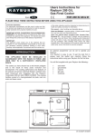
COOKMASTER R40G
OWNERS MANUAL
WARNING: If the information in this manual is not followed exactly, a fire or
explosion may result causing property damage,personal injury or death.
Do not store or use gasoline or other flammable vapors and liquids in the vicinity
of this or any other appliance.
WHAT DO YOU DO IF YOU SMELL GAS
.
Do not try to light any appliance.
.
Do not touch any electrical switch
.
Do not use any phone in your building.
.
Immediately call your gas supplier from a neighbors phone.
Follow the gas suppliers instructions
.
If you can not reach your gas supplier call the fire department.
Installation and service must be performed by a qualified installer, service
agency or the gas supplier.
Installation, Servicing,
Users Instructions
& Cooking Guide
Remember, when replacing a part on this appliance, use only spare parts that you can be assured conform to the safety
and performance specification that we require. DO NOT use reconditioned or copy parts that have not been clearly
authorized by AGA.
PLEASE READ THESE INSTRUCTIONS BEFORE INSTALLING OR USING THIS APPLIANCE.
INSTALLER: LEAVE THESE INSTRUCTIONS WITH THE APPLIANCE.
CUSTOMER: KEEP THESE INSTRUCTIONS FOR FUTURE REFERENCE.
FOR USE IN USA/CANADA
11/09 EINS 512534
CONTENTS
SECTION
CONTENTS
PAGE
4
INSTALLATION SECTION
TECHNICAL DATA
5
SITE REQUIREMENTS
INTRODUCTION
IMPORTANT
GAS SUPPLY
LOCATION
VENT CONNECTION
ELECTRICAL
INSTALLATION
REQUIREMENTS
CLEARANCES
PRELIMINARY INSTALLATION
SITE LOCATION
SETTING COMBUSTION
11
11
12
12
INSTALLATION
INSTRUCTIONS
BURNER ACCESS
ELECTRICAL CONNECTION
TERMINAL STRIP CONNECTIONS
BURNER CONTROL
ELECTRICAL CHECK
COMBUSTION DISCHARGE SAFETY DEVICE
ANCILLARY CONTROLS CHECK
INSTRUCT THE USER
13
13
14
15
15
15
16
16
USERS GUIDE
6
6
6
7-8
9-10
10
17
INTRODUCTION
SAFETY PRECAUTIONS & HINTS
FEATURES/ACCESSORIES
SETTING THE COOKER FOR USE
USING THE TIMER
THE MINUTE TIMER
USING THE AUTOMATIC COOKING FUNCTION
MAIN OVEN OPERATION
COOKING WITH YOUR APPLIANCE
COOKING CHART (ROASTING/BAKING OVEN)
CLEANING & CARING FOR YOUR AGA
SERVICING INSTRUCTIONS
18
19
20-21
22
23-24
25
26
27
28
29
30
31
INTRODUCTION
SERVICE SCHEDULE
32
32
BURNER REMOVAL
PREPARATION
BURNER ACCESS
BURNER REMOVAL
33
33
34
BURNER CHAMBER/
SERVICING
BURNER CHAMBER
35
BURNER SERVICING
BURNER HEAD CLEANING
36
ELECTRICAL CONTROLS
TERMINAL STRIP CONNECTIONS
OVERHEAT SAFETY THERMOSTAT
FLUE SAFETY THERMOSTAT
37
38
38
2
SECTION
CONTENTS
BURNER
COMBUSTION AIR
TEST BURNER ON DRY RUN (NO GAS)
39
40
REPLACEMENT OF PARTS
(BURNER)
ELECTRODES
CONTROL BOX
41
41
REPLACEMENT OF PARTS
(ELECTRICAL CONTROLS)
ELECTRICAL COMPONENT ACCESS
TRANSFORMER
FUSE
TO FIT NEW FLUE SAFETY DEVICE
TO FIT NEW COOKER SAFETY OVERHEAT THERMOSTAT
AND OVEN CONTROL THERMOSTAT
TO FIT NEW TIMER
RE-ASSEMBLE
42
42
42
43
44
WIRING DIAGRAM - BURNER ONLY
WIRING DIAGRAM - APPLIANCE
BURNER DOES NOT START
TROUBLESHOOTING - BURNER
TROUBLESHOOTING CHART
SERVICING OR FAULT
45
46
47
48
49
50
FAULT-FINDING
PAGE
3
44
44
Installation
Section
THE INSTALLATION OF THIS APPLIANCE MUST CONFORM WITH LOCAL CODES, OR IN
THE ABSENCE OF LOCAL CODES, WITH THE NATIONAL FUEL GAS CODE, ANSI
Z223.1/NFPA 54
Remember, when replacing a part on this appliance, use only spare parts that you can be
assured conform to the safety and performance specification that we require. Do not use
reconditioned or copy parts that have not been clearly authorized by AGA.
CAUTION:
THIS UNIT IS HEAVY. PROPER EQUIPMENT AND ADEQUATE
MANPOWER MUST BE USED IN MOVING THE RANGE TO
AVOID DAMAGE TO THE UNIT OR THE FLOOR.
4
PLEASE NOTE: IT IS ADVISABLE TO
CHECK THE ACTUAL SIZE/WIDTH
OF YOUR APPLIANCE BEFORE
FINALLY FIXING ANY KITCHEN
UNITS, SINCE ENAMELLED CAST
IRON CAN VARY IN SIZE
DIMENSIONS IN MM
DESN 512448
TECHNICAL DATA
Gas Inlet
1/2” NPT
Electrical Supply
115 V
Unpacked Appliance Weight - 326 Kg (719 lbs)
60 Hz
Natural Gas
Appliance Inlet
Pressure (MAX.)
Propane
10” w.g.
15” w.g.
- 0.044 w.g. (± 0.012” w.g.)
- 0.044 w.g. (± 0.012” w.g.)
Burner Pressure
(NEGATIVE)
(non-adjustable)
Max Flue Temp.
445ÞF
450ÞF
CO
0 - 50 ppm
0 - 50 ppm
CO2%
8.2% - 9.9%
9.4% - 10.8%
Heat Input
50,000 Btu/hr
50,000 Btu/hr
(non-adjustable)
5
Site requirements
INTRODUCTION
The AGA Cookmaster is a floor standing only cooker, fired by a gas burner. It is suitable for vertical flue outlet only.
IMPORTANT
The burner fitted to this appliance has been designed and constructed exclusively for use with the AGA
Cookmaster and MUST not be used on any other appliances or any other uses.
GAS SUPPLY
Installation Pipes
Pipework from the meter to the appliance must be of adequate size. Do not use pipes of a smaller size than the appliance
gas connection. To avoid undue stress on pipework and burner, adequate support should be used when connecting and
disconnecting union. The complete installation must be tested for soundness and purged in accordance with the
regulations in force.
NOTE: USE SOAPY WATER SOLUTION ON NEW GAS CONNECTIONS TO ENSURE THERE ARE NO GAS LEAKS.
Gas Supply Pipe - U.S. Pipe Threads
NOTE: A GAS CONTROL VALVE MUST BE INSTALLED IN THE GAS PIPELINE EXTERNALLY OF THE RANGE (NOT
SUPPLIED) FOR THE PURPOSE OF TURNING ON OR SHUTTING OFF GAS TO THE APPLIANCE. DO NOT FIT
VALVE BEHIND THE COOKER; IT MUST BE INSTALLED IN AN ACCESSIBLE LOCATION.
The appliance has a 10 mm (1/2”) N.P.T. Male Connection at the front left hand side.
ALL GAS CONTROLS MUST BE U.S. PIPE THREADS.
Maximum Heat Input: 50,000 Btu/h Oven Only
The appliance and its individual shut-off valve must be disconnected from the gas supply piping system during any
pressure testing of that system at test pressure in excess of 1/2 psig (3.5 kPa). The appliance must be isolated from the
gas supply piping system by closing the individual manual shut-off valve during any pressure testing of the gas supply
piping system at test pressures equal to or less than 1/2 psig (3.5 kPa).
Leak testing of the appliance shall be conducted according to the manufacturers instructions.
FLUE SAFETY DEVICE
For safety purposes, a flue safety device is fitted. This will only operate in adverse flue conditions. If the switch has
operated, it should be pushed in only to reset. If this problem persists, it is necessary to determine and rectify the cause.
If it is found necessary to reset more than once, this may indicate a flue blockage.
6
Site requirements
LOCATION
The appliance is floor mounted and must be installed on a solid floor or base of non-combustible material which is capable
of supporting the total weight.
The location chosen for the appliance must permit the installation and the provision of a satisfactory flue and an adequate
air supply. The location must also provide adequate space for servicing and for air circulation around the appliance. See
“Installation of the Appliance”.
The space in which the appliance is to be fitted must have the following minimum dimensions:
Between wall and LH side of appliance - 10 mm (3/8”)
Between wall and RH side of appliance - 10 mm (3/8”)
SHOULD THE WALL PROJECT BEYOND THE FRONT OF THE APPLIANCE, THEN THE GAP AT THE R.H. SIDE
MUST BE INCREASED TO 50 mm (2”) TO ALLOW REMOVAL OF OVEN SHELVES. (SEE FIG. 1).
Height above the raised hotplate - 762 mm (30”)
Max. depth of cabinets above hotplate - 330 mm (13”)
In addition, adequate clearance must be available at the front of the appliance to enable it to be operated and serviced.
Flue pipes and fittings must not be closer than 57 mm (2 1/4”) to combustible materials. Any openings in the wall behind
the appliance and in the floor under the appliance shall be sealed.
Spaces around flue pipes passing through walls or floors should be sealed against the passage of smoke and flame.
Where the cooker is to stand in a recess or against a wall which is to be tiled, in no circumstances should the tiles
overlap the cooker top plate.
50 mm
(2”)
10mm (3/8”)
WALL PROJECTING BEYOND THE
FRONT OF THE APPLIANCE
FIG. 1A
7
Site requirements
INSTALLATION CLEARANCES
REAR DIM ‘A’ COMBUSTIBLE WALL
NON-COMBUSTIBLE WALL
1” (25mm)
0” (0mm)
DIM ‘B’
FLUE PIPE CLEARANCE TO
COMBUSTIBLE WALL
2 1/4” (57 mm)
NON-COMBUSTIBLE WALL
1” (25 mm)
SIDES BELOW HOTPLATE
3/8”
SIDES ABOVE HOTPLATE
2” (50 mm)
WALL CABINET OVERHEAD
30” (762 mm)
WALL CABINET OVERHEAD
MAXIMUM DEPTH
13” (330 mm)
WALL CABINET ALONGSIDE
30” (762 mm)
FIG. 1B
(10 mm)
DESN 512558
8
Site requirements
VENT CONNECTION
A 125 mm (5”) Type B Gas Vent must be used and fastened by screw to the draft hood flue collar.
U.S.
The gas vent must be connected to a chimney or independently and in accordance with Chapter 26, chimney Gas Vent
and Fireplace Systems of the current issue of Equipment and Volume of the ASHRAE Handbook. The gas vent proximity
to combustion materials must be installed as recommended in ANSI/NFPA 211 and according to manufacturers
instructions. Chimneys and vents shall terminate above the roof level and in accordance with the requirements of the
current issue of ANSI/NFPA 211 (see Fig. 2) and be at least 1.53m (5ft) above the flue collar of the draft hood outlet.
Part 7, Venting of Equipment, outlined in the current National Gas Code ANSI Z223, gives detailed guidelines on all these
aspects.
Canada:
The gas vent must be connected to a chimney or independently and in accordance with the CAN/CGA - B149 Installation
Codes.
The air gap between vent and combustible materials must be given for the following types of vent:
(i)
Type B Vent - 25mm (1in) minimum
(ii)
Single wall vent connector - 150mm (6in) minimum
Listed connectors passing through the combustible walls and partitions must be guarded by a ventilated metal thimble not
less than 200mm (8in) diameter.
9
Site requirements
VENT CONNECTION (continued)
Chimneys and vents shall terminate above roof level and in accordance with the requirement of the current issue of the
CAN/CGA - B149 Installation Code (Code W) (see Fig. 2) and be at least 1.53m (5ft) above the flue collar of the draft outlet.
1. If suitable, lined brick chimney is used it must be swept before connection and not less than 150mm (6in) internal
diameter.
2. The top of the chimney should be fitted with an approved terminal.
3. The flue route to the chimney should be as direct as possible. Resistance in the form of directional change should be
kept to a minimum. Right angle bends and horizontal runs should be avoided.
4. The chimney terminal should terminate at the highest possible point, preferably in a freely exposed position.
Termination at the roofs eaves is unacceptable.
5. The AGA Distributor or local gas company should be advised if there is any doubt as to the suitability of the flue.
6. Approved factory made chimneys are acceptable with the appliance and should not be less than 10mm (4in) internal
diameter.
7. In the event of an extractor fan being fitted in the vicinity of the range, compensatory ventilation will be required to
satisfy the demands of the fan without influencing combustion efficiency or chimney flue condition.
ELECTRICAL
110/120V 60 Hz 10 AMP FLEXIBLE CORD AND PLUG PARALLEL TYPE. When installed, the appliance must be
electrically grounded in accordance with local codes or, in the absence of codes, with National Electrical Codes
ANSI/NFPA 70.
An electrical socket must be provided within 6 feet of the LH side of the appliance and easily accessible to the user to
disconnect. Do not position socket above the appliance.
Take special care when cutting holes in wall or floor. Electrical wires may be behind the wall or floor covering and could
cause an electrical shock if you touch them.
Locate any electrical circuits that could be affected by the installation of this product and disconnect power circuit
WARNING
Electrical Grounding Instructions
This appliance is equipped with a (three-prong) grounding plug for your protection against a shock hazard and should
be plugged directly into a proper receptacle. Do not cut or remove the grounding prong from this plug.
Do not have a fuse in the neutral or grounding circuit. A fuse in the neutral or grounding circuit could result in electrical
shock.
Do not use an extension lead with this appliance.
Check with a qualified electrician if you are not sure the appliance is properly grounded.
Failure to follow these instructions could result in death or serious injury.
10
Installation requirements
CLEARANCES
The appliance is floor mounted. The space in which the
appliance is to be fitted must have the following minimum
dimensions.
Between wall and LH side of appliance - 10mm (1/2”)
Between wall and RH side of appliance - 10mm (1/2”)
SHOULD THE WALL PROJECT BEYOND THE FRONT
OF THE APPLIANCE, THEN THE GAP AT THE R.H.
SIDE MUST BE INCREASED TO 50mm (2”) TO ALLOW
REMOVAL OF OVEN SHELVES. SEE PAGE 4 - FIG. 1A.
Above the raised insulating cover handle - 60mm (3”)
In addition, adequate clearance must be available at the
front of the appliance to enable it to be operated and
serviced.
PRELIMINARY INSTALLATION
The appliance is delivered in a fully assembled condition
with the exception of the following items which are
supplied separately packed and require assembly:
The appliance rear distance bracket.
The cooker handrail.
Appliance rear distance bracket: if the rear wall is of
combustible material, there must be an air gap of 25mm
(1”) between the wall and the rear of the cooker. Fit the
rear distance brackets as shown in Fig. 3. Whenever
possible it is recommended that the skirting board is
removed for the width of the appliance to enable the rear
edge of the appliance top plate to make contact with the
vertical wall and avoid a rear gap. (Combustible wall
excepted).
Where the cooker is to stand in a recess or against a wall
which is to be tiled, IN NO CIRCUMSTANCES SHOULD
THE TILES OVERLAP THE TOP PLATE.
FIG. 3
DESN 510226
FIG. 4
DESN 510454 ‘A’
The handrail brackets are held on the front edges of the
cooker top-plate casting. Remove the travel nuts and
replace with the handrail brackets ensuring the fiber
protecting washers are in position. Insert the handrail with
fitted end caps into the brackets, positioning them
correctly, and tighten the locating bolts (Fig. 4).
11
Installation requirements
SITE LOCATION
SETTING COMBUSTION
1. Check that the hearth is level, then remove the
appliance from its transit wooden pallet, and position
it with its back against the wall and in its intended
position for flue connection.
2. Locate and fit flue pipe into socket of flue pipe
adaptor, seal joint with rope and fire cement.
3. Connect and terminate the flue system in accordance
with the regulations in force.
Because this appliance uses a pre-mix burner, no setting
up of combustion is required; the burner automatically
controls the air to gas rate ratio.
Connect the relevant services to the appliance:
1.
2.
3.
Gas
Electric
Flue Pipe
12
Installation Instructions
BURNER ACCESS
- SEE FIG. 5
1. Open the burner access door.
2. Remove (5) inner panel securing screws and remove
panel.
3 Remove the (3) plinth securing screws and remove
plinth.
FIG. 5
DESN 511424
FIG. 6
DESN 512568
ELECTRICAL CONNECTION
- SEE FIG. 6
This appliance comes with a three-prong plug which
should be connected to a proper receptacle. See page 10
(Electrical). This is fitted internally to the terminal strip
shown in Fig. 6 and Fig. 7.
13
Installation Instructions
TERMINAL STRIP CONNECTIONS
FIG. 7
14
Installation Instructions
BURNER CONTROL
When the thermostat is calling for heat, 230V is supplied
to terminals 10 and 11 on the control box and tab 1 and 2
on the fan, energizing the fan.
There will then be a short delay while the control box
checks that the fan is running and pre-purges. Providing
there is gas to the burner, combustion should be
established after approximately 30 seconds.
On first firing after installation or servicing, the burner may
go to lock out, until all the air has been purged out of the
burner. Wait at least 10 seconds before pressing the reset
button. (See Fig. 8).
Check gas cock is in the on position.
Check inlet gas pressure at test point.
GAS SUPPLY
TEST POINT
ELECTRICAL CHECK
RESET BUTTON
Check to ensure electrical safety is carried out by a
competent person.
FIG. 8
COMBUSTION DISCHARGE SAFETY
DEVICE
For safety purposes, a combustion discharge safety
device is fitted. This will only operate under adverse flue
conditions. If the switch has been operated, it should be
pushed in to reset. If this problem persists, contact your
local engineer to determine and rectify the cause. It is
important not to reset more than once as this may indicate
a flue blockage.
WARNING: The combustion discharge safety device
must not be interfered with or rendered inoperative, as
this could interfere with the safe operation of the
appliance and invalidate the appliance warranty.
15
DESN 512346
Installation Instructions
ANCILLARY CONTROLS CHECK
INSTRUCT THE USER
Before leaving the site, check that the operation of cooker
timer and thermostat are capable of controlling the burner
correctly. Check the operation of burner control box.
1. Advise the User that, for continued efficient and safe
operation of the appliance, it is important that adequate
servicing is carried out annually.
2. Hand the Operating Instructions to the User and
demonstrate the correct operation of the appliance and
system controls.
3. Leave the Installation and Servicing Instructions with
the User.
16
Users
Guide
17
INTRODUCTION
Thank you for buying an AGA appliance. To get the best from it, please read this leaflet and carefully follow the instructions
before using your AGA for the first time.
Consumer Protection
As responsible manufacturers we take care to make sure that our products are designed and constructed to meet the
required safety standards when properly installed and used.
IMPORTANT NOTICE: PLEASE READ THE ACCOMPANYING WARRANTY.
Any alteration that is not approved by AGA could invalidate the approval of the appliance and affect your statutory rights.
In the interests of safety and effective use, please read the following before using your new AGA appliance.
The use of a gas cooking appliance results in the production of heat and moisture in the room in which it is installed. Ensure
that the kitchen is well ventilated; keep natural ventilation holes open or install a mechanical ventilation device (mechanical
extractor hood).
Prolonged intensive use of the appliance may call for additional ventilation, (e.g., the opening of a window), or more
effective ventilation, (e.g.,increasing the level of mechanical ventilation where present).
Installation must adhere to Local and National Wiring Regulations and carried out by a Qualified Engineer.
If the weather is very cold, the appliance can be run continuously on the low setting and turned up as required. Do not
use to warm a room with the appliance oven doors open.
Your AGA comes complete with the following:1 Meat Tin
1 Solid Shelf
1 Cookbook
1 Owners Manual
1 Grill Rack
2 Grid Shelves
1 Warranty Card
18
SAFETY PRECAUTIONS AND HINTS
1.
Do not store combustible materials, gasoline or other inflammable vapors and liquids near a range cooker.
2.
Do not operate the appliance with the oven doors open, with the exception of loading and unloading the oven.
3.
Ensure and maintain the continual free passage of air to the burner housing. Do not stand obstacles against a burner
outer door. Loose hair from dogs or cats must not accumulate behind the outer burner door.
4.
Do not use the ovens for storage purposes.
5.
To prevent possible injury, do not step, lean or sit on the appliance doors.
Child Safety
Children MUST be taught safe range practices to prevent possible injury. Listed below are some basic practices we
recommend you read and follow for safe use of this appliance when children are present.
Children are more sensitive to heat than adults. Therefore,
1.
2.
3.
4.
5.
Do not leave children alone or unsupervised near the cooker and discourage them from this area.
Children should not be allowed to climb on any part of the cooker.
Children MUST be taught that the cooker and its utensils can be hot.
Children should be taught that the cooker is not a toy. They should be forbidden to play with the range cooker gas
controls behind burner doors or any other cooker parts.
Let the heavy, hot utensils cool in a safe place that is out of reach of small children.
CAUTION: AVOID STORING ITEMS OF INTEREST TO CHILDREN IN ANY CABINETS INSTALLED ABOVE THE
RANGE TO PREVENT THE RANGE BEING USED TO OBTAIN CABINET ACCESS AND TO PREVENT SERIOUS
INJURY.
Temperatures in cabinet storage spaces above the range may be unsafe for storage of some types of materials such as
volatile liquids or aerosol sprays which can explode.
Ensure spare storage cabinets are capable of supporting the heavy weight of cooking utensils of the range.
The maximum depth of any cabinets installed above the top of the range must not exceed 330mm (13in).
Always wear proper apparel - loose fitting or hanging garments should never be worn while using the appliance.
Use only dry potholders - Moist or damp potholders on hot surfaces may result in burns from steam. Do not let potholders
touch hot heating elements. Do not use a towel or other bulky clothes.
IMPORTANT:- Do not use water on grease fires - smother fire or flame or use dry chemical or foam-type extinguisher.
19
FEATURES/ACCESSORIES
Doors
Fig. 9
To open the doors. Twist the handle slightly to disengage
the door catch from the locking spindle and pull the door
open.
Thermodial
See Fig. 10
FIG. 9
The thermodial positioned on the Roasting/Baking door is
an approximate guide to the internal oven temperature.
All thermodials vary slightly but the settings generally
indicate the following temperatures.
Simmer approximately
Bake approximately
Roast approximately
90-150ºC (190 - 300ºF)
150-200ºC (300 - 400ºF)
200-250ºC (400 - 480ºF)
Remember that by opening the oven door, the
temperature will appear to drop as it registers cooler air
away from the oven. Do not worry, close the door and
after a few minutes, the dial will have regained its
position.
FIG. 10
As an AGA user, you will soon become accustomed to
your individual appliance.
Oven Grid Shelves
See Fig. 11
To ensure the correct operation of the oven grid shelves,
they should be inserted as shown.
ENSURE SHELVES ARE
INSERTED AS SHOWN.
FIG. 11
Solid Plain Shelf
The solid plain shelf can be used in two ways:z
z
As a baking sheet for scones, pizzas, meringues, etc. It is designed to fit directly onto the runners in the oven,
leaving the grid shelves free.
As a heat deflector. If the oven is too hot or food already in the oven is beginning to over-brown, slide the solid plain
shelf onto the top runner above the food and it will help prevent further browning by deflecting and absorbing heat.
It can be used at the beginning of cooking or can be inserted during cooking.
20
FEATURES/ACCESSORIES (continued)
PLAIN SOLID SHELF
TOP RUNNER
SHELF POSITION 1
SHELF POSITION 2
SHELF POSITION 3
SHELF POSITION 4
SHELF POSITION 5
OVEN BASE
FIG. 12
Further accessories, tins, grid shelves, solid shelves, saucepans, aprons and gauntlets, etc. are available from your AGA
dealer.
Control Settings and Temperature Equivalents
MARK
APPROX
TEMP
LOW
250ºF (120ºC)
1
285ºF (140ºC)
2
300ºF (150ºC)
3
340ºF (170ºC)
4
355ºF (180ºC)
5
375ºF (190ºC)
6
390ºF (200ºC)
7
430ºF (220ºC)
8
445ºF (230ºC)
9
465ºF (250ºC)
21
SETTING THE COOKER FOR USE
FIG. 12A
DESN 514596
Before you can use the appliance, it will be necessary to set the time of day.
22
USING THE TIMER
This is a 24 hour clock and when the power supply is initially switched on, or after an interruption in supply, the clock will
show AUTO and 0.00 alternately.
SETTING THE TIME OF DAY
1.
Press and hold the MINUTE TIMER
and COOK TIME
buttons at the same time, (the word AUTO flashes
and the 0.00 is displayed steadily) press the plus + or minus - buttons until the required time of day is displayed. The
time will increase/decrease from 12.00 hrs in minute intervals, slowly at first and then gaining speed.
The cooker is now ready for manual use.
AUTOMATIC COOKING CONTROL
This can be used to set an automatic cooking program. It switches the oven on and off at the pre-set times.
The maximum length of cooking program that can be set is 23 hours and 59 minutes (e.g., delay time + cooking time =
maximum 23 hours and 59 minutes).
Before setting a program, check that the clock is telling the correct time of day, and have the following information at hand.
z
z
z
The length of time the food needs to cook.
The time that the food will finish cooking.
The required oven setting.
SETTING THE AUTOMATIC COOKING PROGRAM
Either the STOP TIME
or the COOK TIME
buttons can be pressed first.
Each setting will remain displayed for 5 seconds before changing back to display time of day.
An example of setting a program using the cook time
button first.
The food needs 2 hours and 30 minutes at 140ºC (284ºF) and is required to be ready by 18.00 hours.
1.
2.
3.
4.
5.
6.
7.
8.
Place the food on the correct shelves of the oven.
Check that the clock is telling the correct time of day.
Press the COOK TIME
button and then the plus + or the - minus buttons until 2 hours and 30 minutes is displayed.
Press the STOP
button and then the plus + or minus - buttons until 18.00 hours is displayed.
Set the oven temperature control to 284ºF (Mark 1).
5 seconds after setting, the clock will display the time of day and AUTO.
When cooking starts, the COOK TIME
symbol illuminates and remains throughout.
When the cooking has finished, a beep will sound (four signals followed by a pause) and continue for 2 minutes, unless
cancelled manually.
The AUTO symbol will flash. To cancel these and return to manual press MANUAL COOK
button twice.
23
USING THE TIMER (continued)
SETTING AN END TIME ONLY, AUTOMATICALLY
1.
2.
3.
4.
5.
Place the food on the correct shelves in the oven.
Press the STOP
button until the time at which the cooking is to end, appears on the display.
Set the oven temperature control.
Cooking will start immediately and the COOK TIME
symbol will illuminate and remain throughout cooking.
When the cooking is finished, a bleep will sound and continue for 2 minutes unless cancelled manually AUTO
symbols will flash.
To cancel and return to manual mode, press the MANUAL COOK TIME
twice.
Programs can be adjusted at any time by pressing the appropriate buttons and the plus + and minus - buttons as described
previously.
CANCELLING A PROGRAM
The cooking program can be cancelled by pressing the COOK TIME
the display.
Press the MANUAL COOK TIME
button and minus - button until 0.00 appears in
button to return the oven to manual mode.
NOTE: When an automatic cooking program has been set, the time of day clock cannot be adjusted.
KEY LOCK
If this mode is activated, a program can be set but it will not be activated ie. an on and off time can be set, but will not
switch the ovens on.
TO ACTIVATE KEYLOCK FUNCTION
1.
2.
3.
Ensure the timer is in manual mode (no active programs).
Hold the MINUTE TIMER
button and COOK TIME
button simultaneously for approximately 8 seconds . The
display will read ON.
Press the plus + button. The display reads OFF and the key symbol appears.
After approximately 5 seconds the time of day reappears next to the key symbol. The key lock is now activated.
TO DEACTIVATE KEYLOCK
1.
2.
3.
Ensure the timer is in manual mode.
Hold the MINUTE TIMER
button and COOK TIME
button simultaneously for approximately 8 seconds. The
display will read OFF.
Press the plus + button. The display reads ON and the key symbol disappears after approximately 5 seconds, the
time reappears and the key lock is now deactivated.
24
THE MINUTE TIMER
SEE FIG. 13
THE MINUTE TIMER
The minute timer works separately from the time of day clock and can be set to time periods from 1 minute to 23.59 hours.
Only a one handed operation is required.
SETTING THE MINUTE TIMER
1. Press the MINUTE TIMER
plus + and minus - buttons.
button the bell symbol will be displayed and 0.00. Set the required time by using the
2. After 5 seconds the display will go back to showing the time of day, the bell symbol will remain steady and the set
time will immediately start to count down, by pressing the MINUTE TIMER
button the display will show the time
remaining.
3. At the end of the set time, a beep will sound (two signals followed by a pause), the bell symbol will flash and continue
for 2 minutes unless cancelled by pressing the MINUTE TIMER
button or MANUAL
button.
4. The setting can be cancelled by pressing the MINUTE TIMER
0.00.
and minus - buttons and running the time back to
NOTE BEFORE USING THE FEATURES PLEASE READ THE USERS INSTRUCTIONS THOROUGHLY.
DESN 512657
FIG. 13
25
USING THE AUTOMATIC COOKING FUNCTION
Using this function on the timer allows the user to select the amount of time the appliance is on and the finish/off time.
HINTS ON THE USE OF THIS FEATURE
*
The AGA should be COLD before starting any automatic cooking where there is a delay in the start time.
Because the AGA is made from cast iron and will therefore retain the heat for a number of hours after it is turned
off, food should NOT be loaded into the appliance for automatic cooking if the AGA has been used earlier in the day,
or is slightly warm, even if it has been turned off for some hours.
*
Only choose foods that require the same amount of time to cook and require the same oven temperature.
*
Food should be as cold as possible when it goes into the oven, especially if there is a delay in the start time. Food
should be thoroughly thawed before it is put into the oven.
*
Warm food should NEVER be placed in the oven if there is a delay to the start of cooking. ie Stews prepared by
frying the meat/vegetables should be cooked immediately.
*
Dishes containing left-over food should not be cooked by this method.
*
On warm days or in centrally heated houses, the delayed start should be minimum, to avoid the growth of harmful
bacteria.
*
Dishes containing liquid should not be too full, to prevent boiling over.
*
At the end of the automatic cooking time although the AGA will switch off automatically it will remain hot for hours
after. FOOD MUST BE REMOVED IMMEDIATELY OR OVER COOKING WILL RESULT.
*
This facility should be used for the main oven only - NOT the lower oven or hotplate.
*
When starting from cold add an extra 40 minutes to the cooking time as an allowance for the AGA to warm up.
*
If a full load is to be cooked add an extra 30 minutes to the total cooking time.
*
ENSURE FOOD IS THOROUGHLY COOKED BEFORE SERVING
*
In the event of a short term power failure the auto cook will automatically adjust the amount of cooking time. As the
AGA retains its heat - OVER COOKING MAY RESULT.
26
MAIN OVEN OPERATION
Note: care should be taken not to touch the hotplate, oven combustion chamber door and flue areas unless a
insulated glove is used, as these areas are hot working surfaces and will burn unprotected skin.
z
z
z
z
z
z
The oven is indirectly heated from the outside by hot gases from the heat source so that no flame or elements within
the oven means full use can be made of the whole cooking area.
The oven is hotter towards the top than the bottom.
To heat the Roasting/Baking and increase the hotplate temperature - turn the cooker control knob to desired setting
as required.
There are 5 runners or shelf positions within the oven on which the grid shelves, solid shelf and meat roasting tin fit
directly.
When left on L setting, your Roasting/Baking oven will maintain a low idling temperature suitable for slow cooking.
As the AGA is made of cast iron, the time for the appliance to heat up and cool down is longer than with a
conventional oven. As an AGA user, you will soon get used to thinking ahead.
Hints
*
Do not forget that the thermodial reflects the temperature in the middle of the oven; by moving the food
higher or lower, or by use of the solid plain shelf, a hotter or cooler temperature can be achieved.
*
The main oven has good all-around temperature. You’ll notice joints of meat gain color more quickly
than in a conventional oven. This is due to the heating from all around the cast iron oven (not just an element
or gas flame). Moisture is quickly sealed in, giving a succulent moist finish.
*
Heat loss when you open the oven door is not as great as that from a pressed metal box type oven; so, you
can look to see how a cake is cooking without it sinking.
*
For perfect baking results, some food such as trays of cookies, small cakes or items nearer the top or on the
floor of the oven, may need turning during cooking. Alternatively, use a lower shelf position and place the
cold plain shelf on the top runner above the cakes to diffuse the heat.
*
One of the many benefits of the cast iron Roasting/Baking oven is that when the oven is hot, the floor of the
oven is hotter than that of a conventional cooker and can be used directly for cooking.
*
No need to bake quiche pastry cases “blind”, just place the flan dish on the oven floor for “soggy-free”
pastry or finish off the base of fruit pies etc. This position is also useful for shallow frying (a cast iron dish
is recommended) with the added advantage that fat splashes are carbonized so cleaning is minimal and
cooking smells are taken away through the flue.
IN THE EVENT OF A POWER FAILURE
During a power failure the appliance will not operate.
If a power failure occurs the memory of the timer is lost and therefore, will need to be reset. This means that the
appliance will not operate until the time of day has been set.
27
COOKING WITH YOUR APPLIANCE
Broiling
The top of the oven is where broiling takes place. When the Roasting/Baking oven is hot, use the meat tin with a grill rack
(used on the highest position) so that the fat can drip into the tray. Position the food on the rack and put into the oven on
the highest runner. The heat from the cast iron roof of the oven will cook and color the food. Turn as necessary.
Turn the grill rack over to the lowest position and it becomes a trivet for roasting meat and poultry. It is also useful as a
cooling rack.
The Hotplate
The rise in temperature of the hotplate corresponds with rise in oven temperature. The higher the Roasting/Baking oven
temperature, the hotter the hotplate. It is graduated, being hotter on the right side suitable for boiling, and cooler on the
left side for simmering and slower cooking.
Hints
*
To get the best results when cooking on the hotplate always use good ground bases. This ensures maximum
contact and heat transfer from the heat source to the food being cooked.
*
The hotplate can be used directly, for making toasted sandwiches, drop scones, etc. See the AGA cookbook
for details.
*
Keeping the hotplate free from crumbs and debris will also maximize efficiency. Even a few small crumbs on
the hotplate will considerably slow down the time it takes for a kettle to boil.
*
Keep the hotplate as hot as possible by always keeping the lids closed when not in use. This also conserves
fuel.
The Simmering/Warming Oven
*
The temperature of the cast iron Simmering/Warming oven is dependent on the temperature in the Roasting/Baking
oven.
*
As a guide, it is approximately half the temperature of the Roasting/Baking oven.
*
This means it can be used as a cooking oven, when the Roasting/Baking oven is at a higher temperature, ideally
200ºC (392ºF) or slightly higher. Food such as casseroles, meringues and milk puddings can then be cooked
satisfactorily.
*
When cooking a casserole or meat dishes in the Simmering/Warming oven, always start off cooking somewhere else
on the AGA first. (ie allow casseroles to come to a boil, and cook for 5-10 minutes on the hotplate or in the
Roasting/Baking oven before being transferred to the Simmering/Warming oven).
*
Although there are runners on the sides of the oven for the grid shelves/meat tin, dishes may also be cooked on the
floor of the oven.
*
Note that if the appliance is left on high setting or run continuously for a long period of time, the temperature of the
Simmering/Warming oven may climb higher than half of the Roasting/Baking oven temperature.
The AGA Cookbook
The cookbook supplied with your AGA is general to all AGA’s. When following the recipes, consult these operating
instructions to ascertain details relevant to your AGA.
28
COOKING WITH YOUR APPLIANCE
COOKING CHART (ROASTING/BAKING OVEN)
Setting
Shelf
Position
SCONES
7
3
10-15 mins
SMALL CAKES
5
4
20 mins (Turn the tray round halfway
through cooking. For best results
place the solid plain shelf on the top
runner)
2-3
5
1 1/2 - 2 hrs
FRUIT CAKE
1
5
Depending on size
SHORT CRUST TARTLETS
6
2 or 3
15-20 mins
SHORT CRUST PIE
6
4 or 5
45 mins
QUICHE
6
Floor
35-40 mins
PUFF PASTRY
8
2 or 3
10-15 mins
LOW
5
1-2
3, 4 or 5
8
4 or 5
20-30 mins
8-9
5
30-40 mins
COOKIES
5
2 or 3
10-15 mins
SOUFFLE
5
4
30-35 mins
YORKSHIRE PUDDING
7
2 or 3
25-35 mins
SEMI-RICH FRUIT CAKE
(Dundee, Cherry Cake, etc)
MERINGUES
CASSEROLES
BREAD - ROLLS
BREAD - LOAF
SLOW/FAST ROASTING
SEE AGA
Any
COOKBOOK FOR
TIMES
Approximate Time
1 1/2 - 2 1/2 hrs
2-3 hrs
Depending on Joint
Shelf Positions are counted downwards (ie., top shelf is No. 1 position). (See Fig. 12)
The positions are a guide only and can be altered.
29
CLEANING AND CARING FOR YOUR AGA
REMEMBER: BE CAREFUL OF THE HOT APPLIANCE!
DO NOT USE A STEAM CLEANER TO CLEAN THIS COOKER.
Enamelled Top Plate and Front Plate
z
z
z
z
z
z
z
It is not advisable to put wet clothes on the handrail: this may craze the enamel.
To keep the vitreous enamelled surface bright and clean, wipe over daily with a soapy damp cloth, followed by a
clean dry cloth.
Wipe off any condensation streaks on the front plate as they occur or the vitreous enamel may be permanently
discolored.
If milk or fruit juice or anything containing acid is spilled on the top plate or down the cooker, be sure to wipe it
immediately or the vitreous enamel may be permanently discolored.
Keep a damp cloth handy while cooking, to wipe up spills as they occur, so they do not harden and become more
difficult to remove later.
For stubborn deposits, gentle localized soaking, not flooding, is easier than rubbing. Hot water and detergent will
soften most burnt stains in about 10 minutes.
A soap impregnated pad can be carefully used on the vitreous enamel.
Oven Door Linings
z
Using oven gloves, carefully lift off the oven doors and lay them on a tea towel to protect the enamel. They can then
cleaned with a cream cleanser or soap impregnated pad. Do not immerse the doors in water as they are packed with
insulating material which will be damaged by excessive moisture.
Insulating Lids
z
Chrome
Wipe over with a soapy damp cloth followed by a polish with a clean dry cloth.
z
Linings
The linings of the insulating lids may be cleaned with a cream cleanser or soap impregnated pad.
Open the lids to allow them to cool a little before cleaning.
Ovens and Hotplate
z
z
z
Use a wirebrush for cleaning the hotplate to remove any burnt spills.
In the Roasting/Baking oven, spills and fat splashes are carbonized at high temperatures. Occasionally brush out with
a wire brush. Do not use oven cleaners.
The Simmering/Warming Oven should also be brushed or wiped out occasionally.
DO NOT USE ANY OVEN CLEANERS
Accessories
z
Oven furniture such as Roasting Tins, Solid Plain shelves, Grid Shelves and Grill Racks should be cleaned in hot
soapy water. Soak if necessary. A nylon scouring pad can be used.
DO NOT PLACE IN THE DISHWASHER OR USE CAUSTIC CLEANERS
30
Servicing
Instructions
When replacing a part on this appliance, use only spare parts that you can be assured
conform to the safety and performance specification that we require. Do not use reconditioned
or copy parts that have not been clearly authorized by AGA.
31
INTRODUCTION
For continued safe and efficient operation of the range, it is important that servicing is carried out annually as
recommended by your AGA Distributor or local gas company. The Cookmaster should be turned OFF by the user the night
preceding the day of servicing so that the range will have cooled down by the following morning.
A HOT APPLIANCE CANNOT BE SERVICED.
DISCONNECT FROM ELECTRICITY SUPPLY BEFORE SERVICING.
WHEN RE-WIRING ANY ELECTRICAL COMPONENTS, REFER TO CIRCUIT DIAGRAM FIG. 32 . BEFORE
ELECTRICAL RE-CONNECTION, CHECK THAT THE APPLIANCE IS ELECTRICALLY SAFE.
NOTE: TURN OFF GAS SUPPLY TO THE APPLIANCE BEFORE SERVICING ANY GAS CARRYING COMPONENTS.
ALWAYS CHECK APPLIANCE FOR GAS SOUNDNESS AFTER COMPLETION.
SERVICE SCHEDULE
Annual Service
BURNER REMOVAL - for cleaning and inspection.
CLEANING - Heat exchanger flueways, ovens and hotplate flueways together with ceramic fibre burner chambers.
BURNER SERVICING
REPLACEMENT PARTS
Always test joints for gas soundness after reassembly.
32
Burner Removal
PREPARATION
WARNING: BEFORE REMOVING SERVICE ACCESS
COVERS, ENSURE THAT ALL ELECTRICAL POWER
HAS BEEN DISCONNECTED.
INNER PANEL
(4 SCREWS)
BURNER ACCESS
SEE FIG. 14
1. Open up the bottom burner access door. Remove
door and put in a safe place.
2. Remove the (4) inner panel securing screws and
remove panel.
3. Remove the (3) base plate screws and remove base
plate.
BASE PLATE
FIG. 14
33
DESN 511424
Burner Removal
BURNER REMOVAL
IMPORTANT: DURING BURNER REMOVAL CARE
MUST BE TAKEN NOT TO DAMAGE THE CERAMIC
FIBRE INSULATION INSIDE THE COMBUSTION
CHAMBER.
SEE FIG. 15
1. Place a sheet on the floor in front of the cooker to act
as a working area.
2. Turn off gas cock.
3. Break gas cock union connection.
4. Disconnect the terminal plug. (See Fig. 15)
5. Unscrew burner locking nuts (2). (See Fig. 16)
6. Remove burner by twisting clockwise and then
remove. (See Fig. 17).
TERMINAL STRIP
GAS SUPPLY
PIPE
FIG. 15
7 WAY PLUG
DESN 512343
FIG. 16
DESN 512339
FIG. 17
34
DESN 512444
Burner Chamber/Servicing
BURNER CHAMBER
IMPORTANT DURING CLEANING CARE MUST BE
TAKEN NOT TO DAMAGE THE CERAMIC FIBER
INSULATION INSIDE THE COMBUSTION CHAMBER.
SEE FIG. 18
1. Lift insulation covers and remove hotplate using lifting
hooks provided.
2. Clean the flueway by inserting the flexible brush through
top plate aperture, directing it towards the flue outlet,
Scrape the deposits towards the burner chamber.
3. Thoroughly clean burner chamber flueway.
4. Carefully vacuum any debris that has fallen down into
the burner chamber.
5. Replace the hotplate ensuring the underside ribs lie over
the oven, and that it seals to the top plate.
FIG. 18
35
DESN 511434
Burner Servicing
BURNER HEAD CLEANING
1. Check the burner head for any signs of damage or
degrading.
2. Examine the condition of the electrodes and that they
are not damaged or loose. Do they need cleaning? (See
Fig. 20).
3. Inspect all gaskets. If necessary, replace them, but
always with the correct type.
4. Check that all electrical connections and cables are
sound, undamaged and have not worked loose.
5. Clean the combustion air fan.
6. Refit all parts, ensuring they are correctly fitted.
7. Refit burner, using a new mounting gasket. Check for
gas soundness and electrical safety before switching
on.
8. Check combustion levels. (8.2%-9.9% CO2).
See Combustion Air (Page 37).
BURNER
AIR
INTAKE
COVER
PULL
36
FIG. 19
DESN 512341
FIG. 20
DESN 512471
Electrical Controls
CONTROL CIRCUIT-EXTERNAL
TERMINAL STRIP CONNECTIONS
37
Electrical Controls
OVERHEAT SAFETY THERMOSTAT
This thermostat is a safety cut-out device which operates if
the control thermostat fails. This device automatically
resets. See Fig. 28.
FLUE SAFETY THERMOSTAT
This thermostat is a safety cut-out device which will operate
under adverse wind or a blocked flue condition.
It is a manually reset device, which can be reset by pressing
in the centre.
38
Burner
COMBUSTION AIR
IMPORTANT: ENSURE THAT THE LOUVERED BASE
PLATE IS IN POSITION DURING COMBUSTION
TESTING AND SETTING PROCEDURES. ENSURE
THE OUTER DOOR IS CLOSED.
TURN THE BURNER ON
After 15 minutes, lift up the R.H. insulating cover and
remove the countersunk screw and insert the sensing end
of a portable indicator to check the CO2 (Carbon Dioxide)
level.
CO
CO2
0 - 50 ppm
8.2% - 9.9%
If these values cannot be obtained, check gas rate, adjust
throttle screw if required and allow readings to stabilize
(See Fig. 21).
THROTTLE
ADJUSTMENT SCREW
FIG. 21
DESN 512341
39
Burner
TEST BURNER ON DRY RUN
(NO GAS)
SEE FIG. 22
Switch on the electricity supply.
Set the time clock as stated in the Users Instructions.
Turn the thermostat to max. allowing the burner to start. The
burner should go to lockout
Reset. Open the gas inlet cock, allowing the burner to
restart.
When the burner is in ‘run’ condition, close the inlet gas
cock. When the flame is extinguished the gas valves
solenoids on the burner should be de-energized almost
immediately.
The control will then allow one restart attempt and should
go to lockout after the expiry of the safety time.
FIG. 22
40
DESN 512346
Replacement of parts (Burner)
The only parts to be replaced are:Electrodes
Electrode Leads
Control Box
If any other parts fails then the whole burner is to be
replaced.
ELECTRODES
See Fig. 23
1. Turn off power to appliance.
2. Unscrew the fixing screw and withdraw the
electrodes.
3. Carefully replace the electrodes, ensuring the gasket
is in place. Tighten screw.
FIG. 23
DESN 512443
FIG. 24
DESN 512442
CONTROL BOX
See Fig. 24
1. Turn off power to appliance.
2. Unplug 12-way connector.
3. Disconnect ignition lead, earth lead and ionization
lead.
4. Unscrew single fixing screw. Withdraw box.
5. Replace control box fixing screw and wires.
(Electrode Wires - See Page 34 , Fig. 20).
41
Replacement of parts (Electrical Controls)
ELECTRICAL COMPONENT
ACCESS
BEFORE REMOVING SERVICE ACCESS COVERS
ENSURE THAT ALL ELECTRICAL SUPPLIES TO THE
APPLIANCE HAVE BEEN TURNED OFF.
SEE FIG. 25
Remove the controls door and place in a safe position.
Remove thermostat control knob.
Remove the (2) cover panel fixing screws.
Remove cover panel. It will be necessary to
disconnect the push on tags from the timer, noting
position of wiring.
5. Remove the (4) control panel fixing screws.
6. Tilt the chassis forwards from the top and lift out. To
fully access the rear of the control chassis, the oven
thermostat capillary and overheat thermostat capillary
should be removed from the oven. Follow instructions
in section ‘TO FIT NEW OVEN CONTROL
THERMOSTAT’, Steps 3 to 6.
1.
2.
3.
4.
FIG. 25
DESN 511443
FIG. 26
DESN 512577
FIG. 27
DESN 512578
TRANSFORMER
SEE FIG. 26
DISCONNECT THE POWER TO THE APPLIANCE.
1.
2.
3.
4.
5.
6.
Remove burner door and base plate.
Remove bracket.
Disconnect transformer.
Replace transformer.
Reconnect wiring.
Replace bracket.
FUSE
SEE FIG. 27
DISCONNECT THE POWER TO THE APPLIANCE
1. Remove burner door and base plate.
.
2. Replace fuse.
42
Replacement of parts (Electrical Controls)
THERMOSTAT
FIG. 28
OVERHEAT
THERMOSTAT
COOKER
TIMER
DESN 511444
TO FIT NEW FLUE SAFETY DEVICE
ENSURE THAT ALL ELECTRICAL SUPPLIES TO THE
APPLIANCE HAVE BEEN TURNED OFF.
SEE FIG. 28
Follow instructions in section BURNER ACCESS Steps 1
to 3.
1. Remove 2 screws securing flue safety device bracket.
2. Withdraw thermostat and remove (2) push on
connectors.
3. Remove thermostat securing nut.
4. Remove phial guide bracket from tube.
5. Pull phial from securing clip and withdraw.
6. Fit replacement device and assemble in reverse order
of removal ensuring the phial is correctly located
within the tube and guide bracket is located under the
safety device fixing bracket.
RESET
BUTTON
FIG. 29
43
DESN 511737
Replacement of parts (Electrical Controls)
TO FIT NEW COOKER SAFETY OVERHEAT
THERMOSTAT & OVEN CONTROL THERMOSTAT
OVERHEAT
THERMOSTAT
SEE FIG. 30
Follow
instructions
in
section
COMPONENT ACCESS , Steps 1 to 6.
ELECTRICAL
1. Undo the two screws on the front of the chassis
which holds the thermostat in place.
2. Remove the (2) push on connectors from back of
thermostat.
3. Open Roasting Oven door and, using a screwdriver,
loosen the rear fixing screws and remove the front
fixing screw of the inner L.H. oven side to expose the
thermostat phial.
4. Slacken the single screw where the phial passes
through the roasting oven side and rotate the cover
plate to open the access hole.
5. Slacken the single screw on the phial securing bracket
and rotate the cover plate.
6. Withdraw the capillary and phial from the oven.
7. Fit replacement thermostat and assemble in reverse
order.
COOKER
THERMOSTAT
THERMOSTAT
PHIALS LOCATION
DESN 511738 A
To complete, follow instructions in ‘RE-ASSEMBLE’.
Steps 1 to 5.
TO FIT NEW TIMER
Follow
instructions
in
section
COMPONENT ACCESS’, Steps 1 to 4.
‘ELECTRICAL
1. Remove timer by depressing retaining clips.
2. Fit new timer ensuring correct location
To complete, follow instructions in section ‘REASSEMBLE’, Steps 2 to 5.
RE-ASSEMBLE
FIG. 30
1. Locate the base of the control chassis into the bottom
of the doorway aperture, tilt the chassis backwards
into position and secure with the (4) screws.
2. Thread the wires for the cooker timer through the
aperture and connect them onto the rear of the cooker
timer fitted in the outer panel.
3. Refix the outer panel in position and secure with the
(2) screws.
4. Replace the thermostat knob.
5. Replace the controls door.
44
DESN 510546
Fault Finding
WIRING DIAGRAM - BURNER ONLY
FIG. 31
45
Fault Finding
WIRING DIAGRAM -APPLIANCE
CAUTION: LABEL ALL WIRES PRIOR TO DISCONNECTION WHEN
SERVICING CONTROLS. WIRING ERRORS CAN CAUSE IMPROPER AND
DANGEROUS OPERATION. VERIFY PROPER OPERATION AFTER
SERVICING.
FIG. 32
46
Trouble Shooting
BURNER DOES NOT START
Burner
Check that the burner has not gone to lockout.
Causes of lockout can be:
z
z
z
z
z
z
No ignition. Electrode incorrectly positioned or insulation cracked, control box faulty.
No gas supply.
Poor combustion.
Flame probe in contact with ground, moisture
present on probe affecting insulation.
Live and Neutral connections reversed.
Inadequate ground control with flame.
General
For access to individual controls refer to section on Replacement Parts. For wiring continuity checks, refer to schematic
wiring layouts.
To check out the electrical wiring at the burner, you will first have to access the burner chamber. Use the following
procedure:1.
2.
3.
4.
Isolate the electrical power supply.
Open up the bottom burner access door. Remove door and put in a safe place.
Unscrew the 4 screws holding the inner panel in place and remove panel.
Unscrew the 3 screws holding the louvered base plate in place and remove plate.
The external mains connections are made to a terminal block situated in the center of the cooker under the oven. Reconnect the electrical supply and check that there is a 110v power supply available across the mains input connections LS
& NS on the terminal block. If not, then check connecting leads, fuse and whether power is available at mains plug. If power
is available across LS & NS, check for continuity across cooker overheat thermostat and flue safety device.
47
Trouble Shooting
TROUBLESHOOTING - BURNER
BURNER WILL NOT START
1 Check that the external wiring is correct.
2. Check the 230v supply on terminal 10 and 11 at control
box base, this will also determine if the thermostats are
calling for heat. (See Fig. 33).
3. Press reset button to ensure that the control box has not
gone to lockout.
4. Check filter is clean on fan inlet.
5. If burner still refuses to start, change control box.
BURNER STARTS, FLAME NOT ESTABLISHED,
CONTROL BOX GOES TO LOCKOUT AFTER END OF
SAFETY
FIG. 33
1.
2.
3.
4.
5.
Check gas supply to valves is turned on.
Check ignition is present after end of pre-purge period.
Check electrodes.
Check earth continuity.
Check ignition lead and flame lead are fitted correctly
and soundly.
BURNER STARTS FLAME ESTABLISHED, CONTROL
BOX GOES TO LOCKOUT
1. Check polarity of wiring for Live and Neutral to control
box base, live to terminal 10 , Neutral onto terminal 11
at control box base.
2. Check flame detection probe is correctly positioned.
Ensure that the probe insulation is free from cracks or
moisture.
Check that the probe is not in contact with other metallic
parts of the burner.
3. Check the burner is effectively grounded and bonded to
the incoming ground wire from the main supply.
4. Check for interference to the flame signal from the
ignition spark. This can be determined with a d.c microammeter (μA). Connect the meter between the terminal
and the incoming wire to the flame probe. Correct
polarity of the meter connections must be correctly
observed with the positive side of the meter connected
onto terminal at the control box. If flame is established
and the meter tends to move in a reverse direction, this
can be an indication that the ignition is causing
interference to the flame signal. It may also be an
indication that there is insufficient earth contact with the
flame. A correct reading should be approximately 3 - 7
μA.
5. Change control box if necessary.
48
DESN 512344
Trouble Shooting
49
Servicing or Fault
BURNER RESET
If a fault occurs on the burner, then it automatically shuts
down and the red button on the front base plate will be
illuminated. This can be reset, after 10 seconds by
depressing the reset button. The reset button is located in
the lower base panel.
OPERATING BY PRESSING WITH FINGER ONLY
Please wait at least 10 seconds between resetting the
lockout button. If resetting the lockout button does not light
the burner immediately, it will be necessary to repeat the
sequence.
Continued lockouts indicate a burner or gas supply
malfunction. This fault should be diagnosed and rectified.
In the event of repeated failure, close the gas valve and
disconnect electrical supply to the appliance and contact
your installer/service engineer.
FLUE SAFETY DEVICE
For safety purposes, a flue safety device is installed. This will
only operate under adverse flue conditions, If the switch has
been operated, it should be pushed into reset and the pilot
re-lit. If this problem persists contact your local engineer to
determine and rectify the cause. It is important not to reset
more than once as this may indicate a flue blockage.
GAS LEAK OR FAULT
If a gas leak or fault exists or is suspected, the unit must be
isolated from the gas and electrical supply. The appliance
must not be used until the fault has been rectified.
Advice/Help should be obtained from your Installer/Servicing
Company.
POWER FAILURE
In the event of a short term power failure, the clock display
will disappear and then return on the power supply being
reinstated.
However if the power supply is interrupted for any length of
time, the clock display will be lost. Follow procedure ‘TO SET
TIME’.
SERVICING
With normal use the cooker will need annual flueway
cleaning and burner maintenance, which should be carried
out by a qualified engineer.
A HOT APPLIANCE CANNOT BE SERVICED.
The cooker thermostat knob should be turned OFF the night
preceding the day of the servicing so that the appliance will
have cooled down by the following morning.
50
BURNER RESET
BUTTON
FIG. 34
FLUE SAFETY
DEVICE
51
For further advice or information contact
your local AGA distributor
With AGA’s policy of continuous product
improvement, the company reserves the right to
change specifications and make modifications to
the appliance described at any time.
AGA
1050 Fountain Street North
Cambridge
Ontario
Canada
N3H 4R7
Business: (519) 650-5775
Fax: (519) 650-3773
Toll-free Phone: 1-877-650-5775
Toll-free Fax: 1-800-327-5609
www.aga-heartland.com
52