1
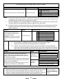
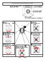
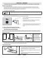
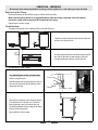
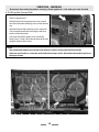
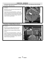
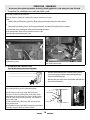
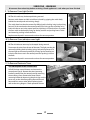
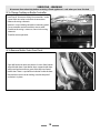
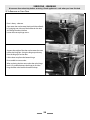
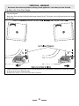
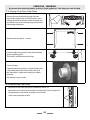
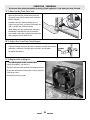
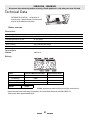
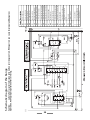
Electric Range Service Instructions This book contains many important safety messages. Always read and obey all safety messages. F107411-01 www.aga-ranges.com WARNING If the information in this manual is not followed exactly, a fire may result causing property damage, personal injury or death. WARNING The anti-tip device supplied with this range must be correctly fitted when the range is installed. This will reduce risk of tipping of the range from abnormal usage or by excessive loading of the oven door WARNING • ALL RANGES CAN TIP • INJURY TO PERSONS COULD RESULT • INSTALL ANTI-TIP BRACKET PACKED WITH RANGE • SEE INSTALLATION INSTRUCTIONS SERVICING WARNING Disconnect from electricity before servicing. Check appliance is safe when you have finished. Sections Diagnostics 5 Servicing Procedures 11 Technical Data 27 Schematic diagram of the Range 28 3 SERVICING WARNING Disconnect from electricity before servicing. Check appliance is safe when you have finished. 4 SERVICING WARNING Disconnect from electricity before servicing. Check appliance is safe when you have finished. Diagnostics Checking the Multifunction Oven 6 Checking the Convection Oven 8 5 Checking the Multifunction Oven Result Check 1 Open the oven door and turn on the oven light Possible Cause Light does not work 1 No power to range 2 3 4 Light bulb failed (most likely cause) Fault in power supply to switch Faulty switch Action 1 Are other parts of the range working - is the clock on, do the ovens and oven neons work? If not then there is probably no power to the range. Investigate power supply. 2 Remove the light bulb (see ‘Servicing Procedures’). Check the bulb with a resistance with a meter. The cold resistance should be very approximately 100 ohms. Replace it if it is open circuit. 3 & 4 If the bulb is OK then move the range forward (see ‘Servicing Procedures’) and remove the rear cover. With the meter check the continuity of the wiring to the bulb and the action of the switch. Replace wiring or switch as necessary. Result Check 2 Turn the function control to the Defrost setting and check that the oven fan starts to spin. Remember - the clock must be set to the time of day before the oven will work. Action 1 2 3-5 Possible Cause 1 2 3 4 5 6 Fan does not spin No power to range Fan blades impeded Fault in power supply to switch Faulty switch Fault in power supply to fan Fan motor faulty Are other parts of the range working - is the clock on, do the oven lights and oven neons work? If not then there is probably no power to the range. Investigate power supply. Remove the oven inner back and check that the fan is not impeded. If the fan is not impeded, not then move the range forward (see the ‘Servicing Procedures’ section for the correct method) and remove the rear covers. With a meter check the continuity of the wiring to the fan and the action of the switch. Replace wiring, switch or fan as necessary. Check 3 Remove the oven racks. Turn the oven temperature control to 400F and turn the function control to each setting in turn and check that the elements start to heat up. See the chart opposite. You should be able to feel the heat from the element after few moments by holding your hand close to the element (DON’T TOUCH THE ELEMENTS!). The bottom element may take slightly longer to heat up. Turn the controls off when you have finished. Result Possible Cause Burnt out element (most likely cause) One element does not heat up. Faulty switch Fault in power supply to element Faulty oven thermostat.(most likely cause) No element heats up Faulty switch Fault in power supply to elements Action One element not working Remove the element - see the ‘Servicing Procedures’ section for the correct procedure. Check it with a resistance meter. Replace with a new element if necessary. If the element is OK then move the range forward (see the ‘Servicing Procedures’ section for the correct method) and check the continuity of the wiring and the thermostat. 6 No element working Remove the range cooktop and check the thermostat and function switch Checking the Multifunction Oven 7 Checking the Convection Oven Check 1 Open the oven door and turn on the oven light Result Possible Cause Light does not work 1 No power to range 2 3 4 Light bulb failed (most likely cause) Fault in power supply to switch Faulty switch Action 1 Are other parts of the range working - is the clock on, do the ovens and oven neons work? If not then there is probably no power to the range. Investigate power supply. 2 Remove the light bulb (see ‘Servicing Procedures’). Check the bulb with a resistance with a meter. The cold resistance should be very approximately 100 ohms. Replace it if it is open circuit. 3 & 4 If the bulb is OK then move the range forward (see ‘Servicing Procedures’) and remove the rear cover. With the meter check the continuity of the wiring to the bulb and the action of the switch. Replace wiring or switch as necessary. Check 2 Result Possible Cause Remember - the clock must be set to the time of day before the oven will work. Remove the oven racks. Turn the oven temperature control to 400F and check that the element start to heat up. You should be able to feel the heat from the element after few moments by holding your hand close to the openings at the top or bottom of the oven inner back. (DON’T TOUCH THE ELEMENT!). Burnt out element (most likely cause) The element does not heat up. Faulty switch Fault in power supply to element Turn the controls off when you have finished. Action Remove the element - see the ‘Servicing Procedures’ section for the correct method. Check it with a resistance meter. Replace with a new element if necessary. If the element is OK then move the range forward (see the ‘Servicing Procedures’ section for the correct method) and check the continuity of the wiring and the thermostat. 8 Checking the Convection Oven 9 10 Servicing Procedures Contents 1. To change oven light bulb. 12 2 How to Move the Range for Servicing 12 3. To Remove a Side Panel 13 4. To Lift up the Ceramic Hob 14 5. To replace a hob element. 15 6. To replace a Cooktop Warmer element. 15 7. To replace the cooktop neon indicator lights pack 16 8. To Remove the Control Panel 16 9. To Remove Oven Light Switch 17 10. To Remove Oven indicator neon Light 17 11. To Remove Electronic Timer 17 12. To Remove a Thermostat 18 13. To Change Cooktop or Broiler Controller 19 14. To Remove Broiler Outer Door Panel 19 15. To Remove an Oven Door 20 16 To Adjust the Oven Door Angle 21 17. To Change Oven Door Outer Panel 22 18 To Remove the Door Latch 22 19. To Remove the Oven Door Seal 23 20. To Adjust the Oven Door Catch Keeper 23 21. To Replace the Cooling fan 23 22. To Remove an Oven Inner Back 24 23. To Replace an Oven Fan 24 24. To Remove an Oven fan Element 24 11 SERVICING WARNING Disconnect from electricity before servicing. Check appliance is safe when you have finished. Servicing Notes Disconnect from electricity supply before commencing servicing, particularly before removing any of the following: control panel, side panels, ceramic hob, or any of the electrical components or cover boxes. Before electrical reconnection check that the appliance is electrically safe. 1. To change oven light bulb. Replacement bulb must be 15w 125-130v lamp, FOR OVENS, heat resistant to 300°C (570°F). Turn off the power at the circuit breaker Make sure the oven is cool. Open the oven door and remove the oven racks. Unscrew the bulb cover by turning counter clockwise. It may be very stiff. Taking care to protect your fingers in case the bulb should shatter, unscrew the old bulb. Screw in the new bulb, screw back the bulb cover. Turn on the circuit breaker and check that the bulb now lights. 2 How to Move the Range for Servicing Follow these procedures to remove appliance for servicing: Turn off the power at the circuit breaker The range is very heavy. Take great care. We recommend two people maneuver the range. Ensure that the floor covering is firmly attached, or removed to prevent it being disturbed when moving the range around. You will need the leveling tool. Remove the drawer Lift up the ends of the plastic clips (one each side) to release the catches holding the drawer to the side runners and at the same time pull the drawer forward and away from the side runners. Pull the drawer out to its furthest point. For safety’s sake push the drawer runners back out of the way. Put the drawer somewhere safe - do not refit it until you have finished, you will need access to the area behind the drawer. Lower the front roller Fit the leveling tool on the rectangular adjuster as shown. Lower the front roller by turning the leveling tool clockwise until the front feet are just clear of the floor. Slide range forward to disengage the range from the anti-tip bracket. Disconnect electrical supply to appliance and unplug the electrical supply cord. 12 SERVICING WARNING Disconnect from electricity before servicing. Check appliance is safe when you have finished. Replaceing the Range Reverse procedure to reinstall the range and lower the front roller. Make sure the anti-tip device is re-engaged properly when the range is replaced. Failure to take this precaution could result in tipping of the range and cause injury. Reconnect the power supply To refit the draw To replace the drawer in the cooker, pull the side rails fully out. Carefully move the drawer back between the rails and rest it on the side rails. At each side hold the front of the drawer and pull the side rail forward so that the clips click into position holding the drawer to the side rails. 3. To Remove a Side Panel Turn off the power at the circuit breaker. Pull the range forward. Pull off the push fit control panel end caps at each end and remove the end fixing screws under the end cap. Remove the retaining screws for each panel (1 at the front and 2 at the rear). The lower front retaining screws (one each side) are situated beneath the lower edge at the front corners of the side panels Reassemble in reverse order. 13 SERVICING WARNING Disconnect from electricity before servicing. Check appliance is safe when you have finished. 4. To Lift up the Ceramic Hob Pull the range forward. Pull off the push fit control panel end caps at each end and remove the end fixing screws under the end cap. Remove the lower front retaining screws (one each side) situated beneath the lower edge at the front corners of the side panels. Swing the side panels to gain access to the hob fixing screws (1 each side) at the top front of the side uprights. Remove these screws. Caution The ceramic hob material is much more sensitive to scratches on the underside than the top. Take care not to touch or scratch the underside of the ceramic as this will weaken the material and cause the top to shatter. Lift up the ceramic hob at the front and prop in position with a non-metallic prop. 14 SERVICING WARNING Disconnect from electricity before servicing. Check appliance is safe when you have finished. 5. To replace a hob element. Lift up the ceramic hob see 4. The elements are now accessible. Remove the screw in the center of the element and slide it out to the side. Disconnect wiring from the element – make a note of the wire colors and terminal connections. Refer to the wiring schematic. Fit new elment and reassemble in reverse order. Check that the wiring is correct as shown in the wiring schematic. 6. To replace a Cooktop Warmer element. Lift up the ceramic hob see 4. The elements are now accessible. Remove the screw holding the element to the support member and slide it out to the side. The picture shows the upper of the two Warmer elments. Disconnect wiring from the element – make a note of the wire colors and terminal connections. Refer to the wiring schematic. Fit new elment and reassemble in reverse order. Check that the wiring is correct as shown in the wiring schematic. 15 SERVICING WARNING Disconnect from electricity before servicing. Check appliance is safe when you have finished. 7. To replace the cooktop neon indicator lights pack Lift up the ceramic hob see section 4. The neon indicator light pack is held to the support bracket by two clips. Either: - Release the pack from the support by freeing the pack location clips from the bracket. Or Remove the mounting screws of the support bracket, and release the pack from the support Disconnect the wiring, noting the colors and connection positions. Fit the replacements pack and reassemble in reverse order. Check that the replacement lights work. bracket fixing screws neon pack locaction clips 8. To Remove the Control Panel Turn off the power at the circuit breaker. Remove the handrail by first removing the 2 plastic screw cover plugs and then the end bracket fixing screws beneath the plugs. Remove the two screws that were hidden beneath the hand rail end brackets. Pull off the push fit control panel end caps at each end and remove the end fixing screws under the end cap. Pull off all the control knobs. Open the broiler and oven doors and remove the control panel fixing screws underneath the control panel. The screws directly below the clock are for the clock fixing bracket - don’t remove them at this stage. Lift the control panel, pull forward and disconnect the wiring from the rear. Reassemble in reverse order. When replacing leads refer to the wiring diagram. Check operation of timer. 16 SERVICING WARNING Disconnect from electricity before servicing. Check appliance is safe when you have finished. 9. To Remove Oven Light Switch Remove control panel (see 8). NB The old switch may be destroyed during removal. Remove switch button and old switch from its bezel by gripping the switch body behind the control panel and twisting sharply The switch bezel can then be removed by folding back its locking ‘wings’ and pushing forward. Fit the new bezel to the control panel by first lining up the raised key on its body with the cut-out in the control panel and pushing it in from the front. Assemble the new switch to the bezel by lining up the key sections and pushing home. Fit the new button by pushing in from the front. Replace control panel in reverse order and test for correct operation. 10. To Remove Oven indicator neon Light Remove control panel (see 8). NB The old indicator neon may be destroyed during removal. Disconnect the wires from the rear of the neon. The light can then be removed by folding back its locking ‘wings’ and pushing forward. Fit the new light to the control panel by first lining up the raised key on its body with the cut-out in the control panel and pushing it in from the front. Replace control panel in reverse order and test for correct operation. 11. To Remove Electronic Timer Turn off the power at the circuit breaker. Pull off the timer control buttons and remove the control panel (See 8). Remove the timer/mounting bracket assembly from the control panel by removing the two fixing screws. Remove the timer from its mounting bracket by depressing the plastic lugs on the timer case, at the same time pulling the unit forward. Reassemble in reverse order. When replacing leads refer to the wiring diagram. Check operation of timer. 17 SERVICING WARNING Disconnect from electricity before servicing. Check appliance is safe when you have finished. 12. To Remove a Thermostat Lift up the cooktop - see 4. Remove the control panel - see 8 Remove the oven shelves. Undo the range rear cover screws and lift covers clear. Right Hand oven From inside the oven remove the two fixings that secure the thermostat phial cover. Push the thermostat sensing bulb back to free it from the clips in the oven back panel. Feed the thermostat capillary out of and clear of the oven noting the routing. Disconnect wiring from thermostat – make a note of the wire colors and terminal connections - and undo the two screws which secure the control to the mounting plate. Refer to the wiring schematic. The thermostat is clipped onto the front switch. Pull the thermostat away from the front switch. Fit the replacement and re-assemble in reverse order. Check that the wiring is correct as shown in the wiring schematic. Ensure that the phial is clipped to the oven rear, positioned centrally between the clips. Check that the thermostat functions correctly. Left Hand Multifunction oven From inside the oven remove the two screws holding the thermostat phial to the oven fan cover at the rear of the oven. Feed the thermostat capillary out of and clear of the oven noting the routing. Disconnect wiring from thermostat – make a note of the wire colors and terminal connections - and undo the two screws which secure the control to the mounting plate. Refer to the wiring schematic. Fit the replacement and re-assemble in reverse order. Check that the wiring is correct as shown in the wiring schematic. Ensure that the phial is clipped to the oven rear, positioned centrally between the clips. Check that the thermostat functions correctly 18 SERVICING WARNING Disconnect from electricity before servicing. Check appliance is safe when you have finished. 13. To Change Cooktop or Broiler Controller Lift up the ceramic hob top (see 4). Remove control panel (see 8). Disconnect wiring from controller – make a note of the wire colors and terminal connections. Refer to the wiring schematic. Remove 2 screws holding controller to mounting panel. Fit new controller and reassemble in reverse order. Check that the wiring is correct as shown in the wiring schematic. Check for correct operation. 14. To Remove Broiler Outer Door Panel Open left hand oven door and remove 2 screws from bottom edge of broiler door. Open broiler door, support broiler door outer panel and remove two screws from top inner face of broiler door. There is a pad of fibre insulation inside the door. Reassemble in reverse order making sure that the pad of insulation is in place. 19 SERVICING WARNING Disconnect from electricity before servicing. Check appliance is safe when you have finished. 15. To Remove an Oven Door Door is heavy - take care. Open oven door and remove Handyrack (where fitted) by springing one side out of the bracket on the door and sliding the other side free. Loosen the two top hinge screws. Support the weight of the door and remove the screw nearest the hinge pin. Swing the hinge up and away from the hinge pin on the door. Lift the door away from the bottom hinge. Re-assemble in reverse order. When replacing the door ensure that the nylon hinge bush is in position between the hinge pin and the hinge bracket at the both the bottom and top. 20 SERVICING WARNING Disconnect from electricity before servicing. Check appliance is safe when you have finished. 16 To Adjust the Oven Door Angle The oven doors are heavy. Transit of the range can cause the oven doors to move so that they are not correctly aligned. Both oven doors are fitted with adjustable door bottom hinges. The hinges can be adjusted to alter the angle of the door. Loosen the bottom hinge fixing screws and use the notch and a flat bladed screwdriver to move the position of the hinge to set the hinge position. Retighten the hinge screws to hold the door in position. 21 SERVICING WARNING Disconnect from electricity before servicing. Check appliance is safe when you have finished. 17. To Change Oven Door Outer Panel Remove the two plastic blanking plugs from the door handles. Remove the 4mm Hex headed screws holding the handle to the door with the hexagon key tool. Remove two screws from top edge and two from bottom edge of the door. Remove outer door panel - 4 screws. Fit door handle to new panel. Fit the plastic blanking plugs to the fixing holes. The handles should be above the fixings. Fit panel to door. If replacing the outer panel on a right hand door with a Thermodial take care to make sure the sensor of the Thermodial is sealed to the door by the rubber grommet. Reassemble in reverse order. 18 To Remove the Door Latch Remove the oven outer door panel as detailed in Section 18. Remove the screws that secure the latch assembly to the inner door panel. Fit the replacement catch and re-assemble in reverse order. Check correct operation of door. 22 SERVICING WARNING Disconnect from electricity before servicing. Check appliance is safe when you have finished. 19. To Remove the Oven Door Seal Open oven door. The seal is held in place by small hooks on the rear face. At the corner pull seal diagonally away from the door centre until that hook is released. Proceed to the next hook and release it in a similar way, and so on. Use force if the hooks are stiff, as the old seal will be discarded. When fitting new seal, position the seal join at the bottom. Hook the new seal in one of the corner holes of the door, and proceed round the door snapping in each hook in turn. 20. To Adjust the Oven Door Catch Keeper Open the oven door and slacken the locknut at the keeper base. Adjust the keeper inward or outward as required, until the desired door operation is obtained. Check the door seal with a strip of paper. Re-tighten the locknut. 21. To Replace the Cooling fan Turn off the power at the circuit breaker. Lift up the cooktop - see section 4 The fan is now accessible under the cooktop at the rear. Disconnect the electrical connections and unscrew the 4 fan fixing screws. Reassemble in reverse order. 23 SERVICING WARNING Disconnect from electricity before servicing. Check appliance is safe when you have finished. 22. To Remove an Oven Inner Back Open the oven door. For the left hand oven unscrew the 2 thermostat phial fixing screws. See section 12 ‘To Remove a Thermostat’ for more detail on the thermostat phial fixing screws. Remove the screws that secure the inner back to the oven rear. Lift the removable panel away. Re-assemble in reverse order. Ensure that the retaining screws are fully tightened. 23. To Replace an Oven Fan Pull the range forward to access the cover boxes at the rear of the range, see the section ‘How To Move the Range for Servicing’. Remove the screws that secure the rear cover and lift it clear. Remove the fan wiring, noting the colors and connection positions. Remove the inner back as detailed in Section 22. Hold the fan blades and undo the centre nut (left hand thread), brass washers, fan blade and Circlip. Undo the nuts that retain the fan and remove it from the cavity rear. Fit the replacement and re-assemble parts in reverse order. Check that the oven operates satisfactorily. 24. To Remove an Oven fan Element Remove the oven inner back as detailed in Section 22. Remove the screws that secure the element within the oven and lift the element away carefully. Disconnect the leads noting the colors and connection positions and connect to the replacement element and re-assemble parts in reverse order. 24 SERVICING WARNING Disconnect from electricity before servicing. Check appliance is safe when you have finished. 25. To Remove the Left Hand Multifunction Oven Bottom and Top Elements Bottom Element Pull the range forward to access the rear of the range, see the section ‘How To Move the Range for Servicing’. Remove the screws that secure the right hand (when viewed from the rear) cover and lift it clear. Remove the 2 screws ‘A’ and allow the plate to drop down. Remove the 2 screws B, holding the element to the bottom sheet. Disconnect the leads, noting the colors and connection positions. Withdraw bottom element. Fit the new element and re-assemble parts in reverse order. Top Element Open the left hand oven door and undo the screws that secure the heat shield and remove the shield. Remove the top element bracket screws and withdraw element. Disconnect the leads, noting the colors and connection positions. Fit the new element and re-assemble parts in reverse order. Check that the oven operates satisfactorily. 25 SERVICING WARNING Disconnect from electricity before servicing. Check appliance is safe when you have finished. 26 SERVICING WARNING Disconnect from electricity before servicing. Check appliance is safe when you have finished. Technical Data DATA BADGE LOCATION: Inside base of drawer cavity - remove drawer. For removal of drawer see installation instructions. Electric: 240V 60Hz Dimensions Overall height (splash not fitted) minimum 35 3/8” (89.8 cm) maximum 36 7/16” (92.5 cm) Overall width 43 5/16” (110cm) See ‘Positioning the Range’ Overall depth without spacer 26 3/4” (68cm). Overall depth with spacer 28 3/4” (73cm) Space for fixing See ‘Positioning the Range’ Minimum space above cooktop 30” (76cm) Connections 240 V 60 Hz Electric Ratings Ovens Left hand Multifunction Oven Fan element 2500W Top element 1200W Browning Element 1150W Bottom element 1000W 2300W Maximum total electrical load at 240V Right hand Fan Oven 2500W Broiler 16700W (approximate total including oven lights, oven fan etc.) Recommended power cord rating 50 ampere in line with Nation Electrical code ANSI/NFPA 70 Total current draw approximately 69.6A 27 28 Right hand end cooktop element controller Left hand end cooktop element - 1200w Left rear cooktop element - 1700W Left front cooktop element - 1200W Right rear cooktop element - 1200W Code Description REC LEE LRE LFE RRE Left hand end cooktop element controller Left rear cooktop element controller Left front cooktop element controller Right rear cooktop element controller Right front cooktop element controller Code Description LEC LRC LFC RRC RFC Code Description L2 Supply (Red) Neutral Supply (White) L1 Supply (BlacK) L2 N L2 Right front cooktop element - 1800W Right hand end cooktop element - 2200W Warmer element 30W Neon indicator light Code Description Black Blue Brown Grey Orange Red Violet White Yellow RFE REE WRM NLI BK BL BR GY O R V W Y Code Color Caution: Label all wires prior to disconnection when servicing controls. Wiring errors can cause improper and dangerous operation. Verify proper operation after servicing. Schematic diagram of the Range 29 Thermal cut out TCO L1 Supply (BlacK) Timer clock TCK L2 Right hand oven switch block RSB L2 Supply (Red) Right hand oven element ROE Neutral Supply (White) Oven light bulb OVL N Right hand oven thermostat OTR L2 Left hand oven thermostat Left hand top outer element LTO OTL Left hand top inner element LTI Oven light switch Left hand fan element LFE OLS Left hand bottom element LBE Oven fan motor Ignition spark generator ISG OFM Ignition switches IGS Left hand oven switch block Cooling fan motor CFM Neon indicator light Broiler controller BTC NLI Broiler switch block BSB LOS Broiler elements BRE Code Description Caution: Label all wires prior to disconnection when servicing controls. Wiring errors can cause improper and dangerous operation. Verify proper operation after servicing. Schematic diagram of the Range 30 31 Aga Ranges 110 Woodcrest Road Cherry Hill, NJ 08003 USA 1.866.4AGA.4USA www.aga-ranges.com Email [email protected]