1
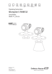
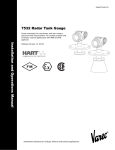
7500 Series Radar Tank Gauges
Continuous and non-contact precision level measurement for
custody transfer and inventory control applications with NMi and
PTB approvals.
Benefits
Application
• 0.5 mm accuracy (2σ value)
The 7500 Series Radar Tank Gauges are used for highly
accurate level measurement in storage tanks and can be
applied in custody transfer applications. It meets the
relevant requirements according to OIML R85 and API
3.1B.
• National approvals (NMi, PTB) for custody transfer.
• Applicable as stand-alone system or tied into tank
gauging systems via the 4590 Tank Side Monitor.
• Easy on-site operation via menu-driven
alphanumeric display.
2-wire i.s. HART
• Easy commissioning, documentation and
diagnostics via operating software (ToF Tool).
Temperature
Radar
• Application-specific antenna selection. Planar
antenna versions allow direct installation on tapered
stilling wells.
2-wire i.s.
DC Power
• Cost-effective and simple installation via 4-wire
cable with HART and 24 V DC intrinsically safe power
supply.
• Gas-tight process connection (second line of
defense) standard for any antenna version.
System
Communications
• Inventory control version with reduced accuracy (3
mm) available for all instrument types.
AC Power
Pressure
Tank
Side
Monitor
For more information, email [email protected] or visit www.tankgauging.com
7500 RTG
Function and System Design
Measuring Principle
The Radar Tank Gauge is a "downward-looking"
measuring system, operating based on the time-offlight method. It measures the distance from the
reference point (process connection) to the product
surface. Radar impulses are emitted by an antenna,
reflected off the product surface and received again by
the radar system.
Antenna Selection
It is essential for each and every application and
installation to evaluate the right antenna type. The
antenna selection depends on the following criteria:
• Type of application (i.e. free space vs. stilling well)
• Installation possibilities (size, location and height of
nozzle)
• Properties of the product stored in the tank (radar
reflectivity, vapor pressure, temperature, etc.)
• Accuracy requirements
The 7500 Series Radar Tank Gauge series radar comes
with 4 basic radar antenna forms.
Horn antenna
The 7530 RTG with horn antenna
is suitable for free space
applications that disallow the use
of a parabolic antenna due to
tank/nozzle geometry. It is
essential that the horn extends
below the nozzle. The general rule
for diameter selection is "the
larger, the better," as a larger aperture of the antenna
generates a narrower beam and has a better gain –
signal to noise (S/N) ratio.
Rod antenna
The 7531 RTG with rod antenna is
used for highly accurate
measurements where only small
diameter nozzles are available and
tanks containing condensing
products (or heavy water
condensation) or corrosive
products, such as sulphur, as the
rod is easy to clean and has good
"drip-off" properties. The
"inactive" length of the antenna should extend below
the nozzle.
Planar antenna (for stilling well)
The 7532 RTG with planar antenna
is specifically suited for stilling
well applications with ranges up to
38 m (124 ft). The emitted circular
mode radar pattern is a must for
high accuracy applications on stilling wells. This special
mode allows the software to compensate for variations
of the inside diameter of the stilling well and layering of
2
adhering product. The diameter of the antenna itself fits
in 6” (DN150) stilling wells directly. Cone adapters allow
installation on larger diameter stilling wells. A good
match between well and adapter is essential. The Varec
planar antenna with pulsed radar technology allows
direct installation even on tapered stilling wells – a
unique feature.
Parabolic antenna
The 7533 RTG with parabolic
antenna is excellently suited for
free space applications up to 40 m
(131 ft). The parabolic antenna is
the largest free space antenna with
the smallest beam angle. It is ideal
for applications close to tank
walls, where a manway cover is
available. The parabolic antenna is also an excellent
choice on products with a low reflectivity, such as
asphalts and bitumens.
Tank Gauging System
The Varec 4590 Tank Side Monitor
provides integrated
communications for sites with
multiple tanks, each with one or
more sensors on the tank, such as
radar, spot or average
temperature, capacitive probe for
water detection and/or pressure
sensors. Multiple protocols out of
the Tank Side Monitor guarantee connectivity to nearly
any of the existing industry standard tank gauging
protocols. Optional connectivity of analog 4...20 mA
sensors, digital I/O and analog output simplify full tank
sensor integration. Use of the proven concept of the
intrinsically safe HART bus (HART multidrop) for all ontank sensors yields extremely low wiring costs, while at
the same time providing maximum safety, reliability
and data availability.
High Accuracy
The mm-accuracy of the 7500 Series Radar Tank Gauge
is achieved using the patented algorithms of the
Microprocessor’s PhaseMaster® software.
Custody Transfer Applications
The 7500 Series Radar Tank Gauge is suitable for
custody transfer and inventory control applications. The
on-site testing has to be done in compliance with the
applicable regulatory standards. The 7500 Series Radar
Tank Gauge can be sealed after successful on-site
calibration to be protected against any access to the
electronics compartment and any changes of software
settings. If the 7500 Series Radar Tank Gauge is used
for custody transfer or inventory control, any
temperature influence on the tank shell hight can be
compensated for using the Tank Side Monitor (TSM). In
addition, the vertical movement of the gauge reference
Varec, Inc.
Radar Tank Gauge
point due to the hydrostatic tank deformation can be
compensated in the Tank Side Monitor. A Tank Side
Monitor can provide 24 VDC for a 7500 Series Radar
Tank Gauge. The Tank Side Monitor can communicate
with up to 6 devices via HART Multidrop.
Reference Operating Conditions
According to OIML R85:
• Temperature = -25 °C... +55 °C (-13…+131 °F)
• Atmospheric pressure
• Relative humidity (air) = 65 % ±15%
• Medium properties: e.g. medium with good
reflectivity and calm surface.
• Tank diameter: signal beam hits the tank wall only at
one side.
• No major interference reflections inside the signal
beam.
Proof of Accuracy of Custody Transfer Versions
The accuracy of each 7500 Series Radar Tank Gauge is
established through a calibration certificate that
records the absolute and relative error at 10 equidistant
points during the final test. A Laser Interferometer
(Jenaer Messtechnik ZLM 500) with an absolute accuracy
of 0.1 mm is used as a reference for the free space
measurements with 7530 RTG, 7531 RTG and 7533
RTG.
For stilling well measurements with 7532 RTG, a NMI /
PTB calibrated tape with an absolute accuracy of 0.25
mm is used. Each 7500 Series Radar Tank Gauge is
delivered with the PTB and NMi type approval.
Additional initial factory verifications for custody
applications are available on demand for radar
instrument 7500 Series Radar Tank Gauge.
Inventory Control Versions
All device types can be delivered as "Inventory Conctrol
Versions" with a reduced accuracy of ± 3 mm (under
reference conditions).
To these versions, the calibration certificate or custody
transfer type approval is NOT attached. The "Inventory
Control Versions" can be selected by choosing the
option »R« in the order code section »Custody transfer
approvals«
HART
4-wire
Supply voltage:
16…253 VAC
FuelsManager
Software
Level
Temperature
8130 RTU
or
8300 TGI
+24V
+5V
+15V
-15V
CPU
COMM
I/O
ERROR
Pressure
Example System Diagram
Technical Information
3
7500 RTG
Installation Guidelines
Configuration
The Radar Tank Gauge is commissioned by entering an
empty distance E (=zero) and a full distance F (=span)
that correspond with 4mA and 20mA current output.
A linearization table (max. 32 points) which can be
configured locally or remotely provides engineering
units and a linear output signal for spheres, horizontal
cylindrical tanks and vessels with conical outlet.
On-site operation and configuration is performed
using:
• The built in display and operating module VU331
• A Personal Computer, service adaptor (FXA193) and
"ToF Tool - FieldTool Package" operating software.
Remote operation and configuration can be performed
using:
• A Personal Computer, service adaptor (FXA195) and
"ToF Tool - FieldTool Package" operating software.
• A Personal Computer, TSM (Tank Side Monitor) and
the operating software FuelsManager.
Measuring Range
The usable measuring range depends on the size of the
antenna, the reflectivity of the medium, the mounting
location, and eventual interference reflections.
The following tables describe the groups of media as
well as the achievable measuring range as a function of
application and media group. If the dielectric constant
of a medium is unknown, it is recommended to assume
media group B to ensure a reliable measurement.
4
Media
group
DC
(εr)
Examples
A
1.4...
1.9
non-conducting liquids, e.g. liquefied gas
(LPG). For more information please contact
your Varec representative.
B
1.9...
4
non-conducting liquids, e.g. benzene, oil,
toluene, white products, black products,
crudes, bitumen/asphalts, …
C
4...10 e.g. concentrated acids, organic solvents,
esters, aniline, alcohol, acetone, …
D
> 10
conducting liquids, e.g. aqueous solutions,
dilute acids and alkalis
Varec, Inc.
Radar Tank Gauge
Measuring range depending on vessel type, conditions, and product for Micropilot S
Media group
Stilling well/ Bypass
Free space (Storage tank)
Measuring range
7532 RTG ≥ DN150
7533 RTG
7530 RTG
DN150/200/250
7531 RTG
38 m/124 ft
—
—
—
38 m/124 ft
40 m/131 ft
DN150: 10 m/33 ft
DN200/250: 15/49 ft m
10 m/33 ft
ε
38 m/124 ft
40 m/131 ft
DN150: 15 m/49 ft
DN200/250: 20 m/65 ft
15 m/49 ft
ε
38 m/124 ft
40 m/131 ft
DN150: 20 m/65 ft
DN200/250: 25 m/82 ft
20 m/65 ft
NMi: 20 m/65 ft
PTB: 30 m/98 ft
NMi: 25 m/82 ft
PTB: 30 m/98 ft
NMi and PTB:
DN150: 20 m/82 ft
DN200/250: 25 m/82 ft
NMi and PTB: 10
m/33 ft
B
ε
DC (εr) = 1.9...4
C
DC ( r) = 4...10
D
DC ( r) > 10
A
Measuring range
DC ( r) = 1.4...1.9
max. measuring range
with custody transfer
approvals
Blocking distance
The blocking
distance (= BD) is the
minimum distance
form the reference
point of the
measurement
(mounting flange) to
the medium surface
at maximum level.
Blocking
distance (BD)
reference point of
measurement
from flange
BD
Max.
Level
20 mA
100%
Stilling well /
Bypass
Free space (Storage tank)
7532 RTG
7533
RTG
7530
RTG
7531
RTG
1 m/40"
1 m/40"
Length
of horn
(see Page
28)
390
mm/15"
540
mm/21"
Note! If an antenna
extension is used, its
length has to be added.
Note! Inside the blocking distance of 7532 RTG/7533 RTG,
a reliable measurement can not be guaranteed.
Technical Information
5
7500 RTG
Measuring Conditions
propagate completely outside the tube. It must be
taken into account that the accuracy may be reduced
in the area C. In order to guarantee the required
accuracy in these cases, it is recommended to
position the zero-point at a distance C above the
tank bottom.
• The measuring range begins where the beam hits
the tank bottom. Particularly with dish bottoms or
conical outlets the level cannot be detected below
this point.
• For overspill protection, it is possible to define a
safety distance (SD) additionally to the blocking
distance (BD).
• In principle it is possible to measure up to the tip of
the rod and horn antenna. However, due to
considerations regarding accuracy corrosion and
build-up, the end of the measuring range should not
be chosen any closer than 50 mm (2”) to the tip of
the rod and horn antenna.
• Depending on its consistence, foam can either
absorb microwaves or reflect them off the foam
surface. Measurement is possible under certain
conditions.
• In applications with planar or parabolic antennas,
especially for media with low dielectric constants,
the end of the measuring range should not be closer
than 1 m (40”) to the flange.
• Distance B defined the smallest recommended
measurement range.
• Tank diameter and height should be at least
dimensioned such that a reflection of the radar
signal on both sides of the tank can be ruled out.
• This safety distance (SD) is set to 0.1 m (4") by
default for 7530 RTG (horna antenna) and 7531 RTG
(rod antenna) and generating an alarm in case the
product level rises inside the safety distance.
• 7530 RTG, 7531 RTG, 7533 RTG: In case of media
with a low dielectric constant (groups A and B), the
tank bottom can be visible through the medium at
low levels (low height C). Reduced accuracy has to be
expected in this range. If this is not acceptable, we
recommend positioning the zero point at a distance
C above the tank bottom in these applications.
7532 RTG: The zero should be positioned at the end
of the tube, as the electromagnetic waves do not
FMR530/531/533
FMR532
BD
100%
A
SD
max. level
• For 7533 RTG (parabolic antenna) and 7532 RTG
(planar antenna) the safety distance (SD) is set to 0.5
m (20") by default, generating an alarm in case the
product level rises inside the safety distance.
BD
A
100%
SD
max. level
B
B
0%
C
C
0%
ØD
Measuring Conditions & Gauge Orientation
6
reference: flange / BD (cf. picture)
reference: antenna tip (cf. picture)
Blocking distance
Safety distance
recommended additional settings
BD [m / ft]
SD [m / ft]
A [mm / inch]
B [m / ft]
C [mm / inch]
7530 RTG (horn)
horn length
0.1 / 0.3
50 / 2
0.5 / 1.6
150…300 / 6…12
7531 RTG (rod)
0.39/1.3 or 0.54/1.8
0.1 / 0.3
50 / 2
0.5 / 1.6
150…300 / 6…12
7532 RTG (planar)
1 / 3.28"
0.5 / 1.6
1000 / 40
0.5 / 1.6
150…300 / 6…12
7533 RTG (parabolic)
1 / 3.28
0.5 / 1.6
1000 / 40
0.5 / 1.6
150…300 / 6…12
Varec, Inc.
Radar Tank Gauge
Note! The behaviour in case of the measuring range being
exceeded can be freely set: the default setting is a current of
22 mA and the generation of a digital warning (E681).
• Stilling well: a stilling well can always be used to
avoid interference. The 7532 RTG with planar
antenna is recommended for stilling wells with a
diameter DN150 (6”) and larger.
• Metallic screens (3) mounted at a slope spread the
radar signals and can, therefore, reduce interference
echoes.
BD
SD
1
• Antenna alignment.
α
3
2
Tank Installation
Tank Installations
The Radar Tank Gaugeis equipped with functions to
suppress interference echoes. The user can activate
these functions. They ensure that interference echoes
(i.e. from edges and weld seams) are not interpreted as
level echo.
• Avoid any installations (1), like limit switches,
temperature sensors, etc., inside the signal beam.
• It is essential that HiHi alarm is below the blocking
distance (BD) and the safety distance (SD).
• Symmetrical installations (2), e.g. vacuum rings,
heating coils, baffles, etc., can also interfere with the
measurement.
Please contact Varec for further information.
Note! The 7500 Series Radar Tank Gauge 7532 RTG is
designed for level measurement in stilling wells only!
Caution! Make sure that only one tank wall (not two tank
walls) is directly hit by the radar beam!
Mounting in manway
The parabolic antenna can be mounted on a manway
cover. The manway cover must have an opening with a
diameter D1 or D2 for mounting of the antenna. It has
to be possible to remove the cover in order to mount the
antenna. Please consider the maximum height of the
nozzle (H max. = 200 mm/8") for the diameter of the
basis.
Mounting in a stilling well
• The stilling well should be constructed from metal
(no enamel coating, plastic on request) with a
constant diameter.
• When using a 7532 RTG, an increase of the pipe
diameter from DN150 to DN200 / DN200 to DN250
/ DN250 to DN300 is acceptable. A larger stepwidth for the increase of the pipe diameter (e.g.
DN150 to DN300) is possible if the upper part of the
pipe has a suitable length. The length of the stilling
well enlargement must be kept. In this case, the
upper end of the pipe must have a minimum length
of 0.5 m (20“) before the diameter increases. If the
length is less than L, please contact Varec in order to
determine a suitable antenna adapter (separable
antenna horn). Ideally, a sample hatch is used.
• Any rectangular increase of the pipe diameter has to
be avoided.
Gauge orientation
• Recommended distance (1) wall - outer edge of
nozzle:: ~1/6 of tank diameter.
• Welding seam as smooth as possible and on the
same axis as the slots.
• Not in the centre (3), interference can cause signal
loss.
• Slot width respectively diameter of holes max. 1/10
of pipe diameter, de-burred. Length and number do
not have any influence on the measurement.
• Not above the fill stream (4).
• It is recommended to use a weather protection cover
(2) in order to protect the transmitter from direct sun
or rain. Assembly and disassembly is simply done by
means of a tension clamp.
Optimisation options
• Antenna size: the bigger the antenna, the smaller
the beam angle, the less interference echoes.
• Mapping: the measurement can be optimized by
means of electronic suppression of interference
echoes.
Technical Information
• Slots offset 180° (not 90°).
• Maximum gap allowed between the antenna/horn
and the inside of the stilling well is 5 mm (3/16").
• At any transition (e.g. when using a ball valve or
mending pipe segments), no gap may be created
exceeding 1 mm (0.04").
• The stilling well must be smooth on the inside
(average roughness Rz ≤ 6.3 μm). Use extruded or
parallel welded stainless steel pipe. An extension of
the pipe is possible with welded flanges or pipe
sleeves. Flange and pipe have to be properly aligned
at the inside.
7
7500 RTG
• Do not weld through the pipe wall. The inside of the
stilling well must remain smooth. In case of
unintentional welding through the pipe, the weld
seam and any unevenness on the inside need to be
carefully removed and smoothed. Otherwise, strong
interference echoes will be generated and material
build-up will be promoted.
Note! Please refer to the sepcific instrument’s Installation &
Operation Manual for complete installation instructions
Installation in tank (free space):
Mark on process connector facing the nearest tank wall!
90
°
90
°
marker at flange neck
°
90
mark at instrument flange
°
90
°
90
°
90
±2°
90
°
90
°
0…
2°
90
°
DN150
ANSI 6”
2°
DN200…250
ANSI 8…10”
90
°
Turn housing
marker at instrument flange
90
°
90
°
The housing can be turned 350°
in order to simplify access to the
display and the terminal compartment
°
90
T12 housing
2
±2°
90
°
0…
2°
DN50
ANSI 2”
90
°
DN80…150
ANSI 3…6”
3
1
Allen key
4 mm
tighten strongly
by hand
Installation in stilling well:
Mark on process connector of 7530 pointed
towards the slots or vent holes!
90
°
mark at instrument flange
DN50
ANSI 2”
DN80…150
ANSI 3…6”
Example Installations
8
Varec, Inc.
Radar Tank Gauge
Inputs and Outputs
Terminal Assignment
Overvoltage Protector
The 4-wire cable is connected to the screw terminals
(wire diameter 0.5…2.5 mm) in the terminal
compartment. Use 4-wire twisted pair cable with screen
for the connection. Protective circuitry against reverse
polarity, RFI, and over-voltage peaks is built into the
device.
The 7500 Series Radar Tank Gauge is equipped with an
internal overvoltage protector (600 Vrms surge arrester)
according to DIN EN 60079-14 or IEC 60060-1 (impulse
current test 8/20 μs, Î = 10 kA, 10 pulses). Additionally,
the instrument is protected by a galvanic insulation of
500 Vrms between the power supply and the (HART)
current ouput. Connect the metallic housing of the
7500 Series Radar Tank Gauge to the tank wall or screen
directly with an electrically conductive lead to ensure
reliable potential matching.
1 2 3 4
• Connect the external overvoltage protector and the
7500 Series Radar Tank Gauge to the local potential
matching system.
Accessing the terminal compartment
power:
24 VDC
(16…30 V)
e.g. from
NRF590
• Potentials shall be equalised both inside and outside
the explosion hazardous area.
signal:
24 VDC
e.g. from
NRF590
• The cable connecting the overvoltage protector and
the 7500 Series Radar Tank Gauge shall not exceed
1 m in length;
• The cable shall be protected e.g. routed in an
armoured hose.
HART
alternatively
Output Signal
Commubox
FXA195
DXR375
4…20 mA with HART protocol (e.g. for multidrop
connection to the 4590 Tank Side Monitor): this version
can be operated via the PC operating software ToF Tool.
The instrument supports both point-to-point and
multidrop operation.
communication
resistor
(> 250 ? )
test sockets
(output current)
Note! For measurements with mm accuracy the measured
variable must be transmitted using HART protocol to ensure
the necessary resolution.
1 2 3 4 5
1
2
3
4
Installation with additional overvoltage protector
HAW262Z/HAW56xZ (see XA081F-A "Safety
instructions for electrical apparatus certified for use in
explosion-hazardous areas").
Galvanic Isolation
5
• 500 V towards ground.
• 500 V between power supply and signal.
Terminal Connections
Note! Minimum load for HART communication: 250 Ω
Note! Refer to the 4590 TSM technical information for connection to the 4590 TSM.
Input Power
The 7500 Series Radar Tank Gauges operate on a DC
voltage 16-36 VDC power source.
Communication
Terminal
voltage
min.
max.
Power supply Standard
U (20 mA) =
16 V
36 V
Power supply Ex
U (20 mA) =
16 V
30 V
Signal Ex
U (4 mA) =
11.5 V
30 V
U (20 mA) =
11.5 V
30 V
Technical Information
9
7500 RTG
Operation
Operation Concept
The display of the process value and the configuration
of the Radar Tank Gauge occur locally by means of a
large 4-line alphanumeric display with plain text
information. The guided menu system with integrated
help texts ensures a quick and safe commissioning.
Display and operation can occur in one out of six
languages (English, German, French, Italian, Dutch, and
Spanish). During the first start-up, the instrument
explicitly asks for the desired unit / language.
Remote commissioning, including documentation of
the measuring point and in-depth analysis functions, is
supported via the ToF Tool, the graphical operating
software for Varec instruments.
Access to the electronics can be prevented by means of
a custody locking switch that locks the device settings.
The custody locking switch can be sealed for custody
transfer applications.
On-site Operation
the instruments. It is compatible with the following
operating systems: Win95, Win98, WinNT4.0, Win2000
and Windows XP.
The ToF Tool supports the following functions:
• Online configuration of transmitters
• Signal analysis via envelope curve
• Loading and saving of instrument data (Upload/
Download))
• Documentation of measuring point
Note! More information on the ToF Tool can be found on the
CD-ROM which is supplied with the instrument.
Menu-guided commissioning:
Signal analysis via envelope curve:
• Connection options:
• HART with Commubox FXA191/195
• Service-interface with adapter FXA193 (RS232C) or
FXA291 and ToF Adapter FXA291 (USB)
The LC-Display VU331 (Four lines with 20 characters
each.) allows configuration via 3 keys directly at the
instrument. It can be removed to ease operation by
simply pressing the snap-fit. It is connected to the
device by means of a 500 mm cable.
All device functions can be set through a menu system.
The menu consists of function groups and functions.
Within a function, application parameters can be read or
adjusted. The user is guided through a complete
configuration procedure.
LCD
(liquid crystal display)
symbols
–
+
E
ToF Tool Operating screen shots
Software Reliability
snap-fit
sealing pin
custody locking
switch
red LED
green LED
3 keys
LC-Display VU331
To access the display, it is possible to open the cover of
the electronics compartment even in an explosion
hazardous area.
Remote Operation
The ToF Tool is a graphical operation software for
instruments from Varec that operate based on the timeof-flight principle. It is used to support commissioning,
securing of data, signal analysis, and documentation of
10
The software used in the radar instrument 7500 Series
Radar Tank Gauge fulfills the requirements of OIML
R85. This particularly includes:
• cyclical test of data consistency
• non-volatile memory
• segmented data storage
The radar instrument 7500 Series Radar Tank Gauge
continuously monitor the compliance with accuracy
requirements for custody transfer measurements
according to OIML R85. If the accuracy cannot be
maintained, a specific alarm is generated on the local
display and via the digital communication.
Varec, Inc.
Radar Tank Gauge
Signal on Alarm
Error information can be accessed via the following
interfaces:
• Local display:
–Error symbol
–Plain text display
–LED’s: red LED continuously on = alarm, red LED
flashes = warning
• Current output
• Digital interface
Linearization
The linearization function of the 7500 Series Radar
Tank Gauge allows the conversion of the measured
value into any unit of length or volume. Linearization
tables for calculating the volume in cylindrical tanks are
pre-programmed. Other tables of up to 32 value pairs
can be entered manually or semi-automatically.
Technical Information
11
7500 RTG
Maintenance
Spare Parts and Maintenance Kits
The 7500 series RTG is designed and manufactured to
provide accurate and reliable operation without an
intensive maintenance schedule.
Varec can provide spare parts, preventive maintenance
advice, training and warranties. Please consult your
Installation and maintenance manual or a
representative for more details.
Cleaning the Antenna
The antenna can get contaminated, depending on the
application. The emission and reception of microwaves
can thus eventually be hindered. The degree of
contamination leading to an error depends on the
medium and the reflectivity, mainly determined by the
dielectric constant εr. If the medium tends to cause
contamination and deposits, cleaning on a regular basis
is recommended. Care has to be taken not to damage
the antenna in the process of a mechanical or hosedown cleaning. The material compatibility has to be
considered if cleaning agents are used! The maximum
permitted temperature at the flange should not be
exceeded
12
Varec, Inc.
Radar Tank Gauge
Accessories
Antenna Extension for 7530 RTG
UNI Flange
The antenna extension has to be selected such that the
horn extends below the nozzle.
Varec UNI flanges are designed for non-pressurized
operation. Typical pressure fluctuations of breather
valves can be tolerated. The number of bolts has
sometimes been reduced. The bolt-holes have been
enlarged for adaption of dimensions, therefore, the
flange needs to be properly aligned to the
counterflange before the bolts are tightened.
A-A
Ø 63.2
Ø 23
Variant 1000
Ø 12
8
Radar
4 x Ø7 shifty at 90°
for little
bolts
Ø 78
1
If the horn diameter is greater than the nominal width
of the nozzle, the antenna including the extension is
mounted from inside the vessel. The bolts are tightened
from outside, with the instrument lifted up. The
extension has to be selected such that the instrument
can be lifted by at least 100 mm (4”).
Ø 101
sealing surface
Variant 2000
A
A
4x90°
15°
6x
60
°
> 100 mm/4”
K
D
Variant 3000
12x3
Ø 29
0°
Antenna extension
Ø 26
K
D
K
material: 1.4301
D
Uni Flange
Antenna extension dimensions
Technical Information
Version
Compatible
with
D
[mm]
K [mm]
Type plate
no.
1000
DN150 PN16
ANSI 6"
150lbs
JIS 10K 150
280
240
9424553001
2000
DN200 PN16
ANSI 8"
150lbs
JIS 10K 200
340
294.5
9424553002
3000
DN250 PN16
ANSI 10"
150lbs
JIS 10K 250
405
358
9424553003
4000
DN300 PN16
ANSI 12"
150lbs
JIS 10K 300
482
410 (for DIN)
942455431.8 (for ANSI) 3004
400 (for JIS)
404.5 (for DIN
+ JIS)
13
7500 RTG
Sample Hatch for 7532 RTG
Weather Protection Cover
For control and cleaning purposes for sample taking as
well as for hand dipping (tape), a sample hatch is
recommended. The sensor head of 7532 RTG (planar
antenna!) can be easily checked in the area of the
opening. Manual gauging with gauge rod or tape is
possible without removal of the transmitter. The lower
edge of the opening is the reference for the gauging.
The construction is only suitable for non-pressurized
operation and should be used for the planar antenna
version 7532 RTG only.
A weather protective cover made of stainless steel is
available for outdoor mounting (order code: 5431990001). The shipment includes the protective cover and
tension clamp.
Note! The sample hatch is not part of the standard offering
from Varec. Please contact Varec for further information.
Weather Protection Cover
Pivoting Element for 7500 Series Radar Tank
Gauge 7532 RTG
The pivoting element is
intended for the 7500 Series
Radar Tank Gauge with planar
antenna. It serves to swivel the
7500 Series Radar Tank Gauge
from the measuring position,
e.g. to clean the antenna or dip
the tank. The pivoting element
is not part of the standard
offering from Varec. For more
information please contact
your Varec representative.
Note! When mounting, avoid any gaps within the path of the
beam.
Sample Hatch
14
Flange
DN150
DN200
DN250/300
PN [bar]
16
16
16
A [mm]
110
140
170
L [mm}
—
300
450
Flange
ANSI 6"
ANSI 8"
ANSI 10"
PN [lbs]
150
150
150
A [mm]
110
140
170
L [mm}
—
300
450
Varec, Inc.
Radar Tank Gauge
Roof Reflector
Measurements on floating roofs are not recommended
for highly accurate measurements due to the unsteady
movements of the floating roofs. A special reflector can
be used for applications on floating roofs (not for 7532
RTG with planar antenna!).
FMR 530
Optimum mounting position
• Positioning of the reflector on a floating roof:
• The upper edges of the reflector have to be aligned
horizontally.
• For slanted locations (e.g. dome-shaped floating
roof), the feet must be extended accordingly.
Construction hints
The construction serves as retroreflector such that a
tank roof incline does not influence the measured value.
The cross-sectional area shouldn‘t be smaller than
specified in the figure above to receive and transmit
enough energy
roof reflector
horizontal top edge
The construction should be open in the bottom part to
allow rainwater to drop out. Thin stainless steel sheets
should be used, to prevent the construction from
becoming too heavy.
Note! The roof reflector is not part of the standard offering
from Varec. Please contact Varec for further information.
e.g.floating roof
e.g. tank
Top View Of Reflector
Roof Reflector
Technical Information
15
7500 RTG
Technical Specifications
The following specifications apply to the 7500 Series
Radar Tank Gauge 7530, 753, 7532 and 7533 RTG over
the normal (ambient) operating temperature rangethat
can be calibrated for inventory control and custody
transfer applications according to regulatory standards
in compliance with OIML R85.
Environmental
T
Ambient
temperature
-40 °F and +185 °F
(-40 °C and +85 °C)
For calibration to regulatory
standards: -25 °C ... +55 °C
(-30 °F…+140 °F)
With Tu<-20 °C and Tu>+60 °C the
operability of the LC-display is
reduced. A weather protection cover
should be used for outdoor operation
if the instrument is exposed to direct
sunlight.
Process pressure
limits
7530 RTG: 0…40 bar / 14.5…580 psi
(option 64 bar / 928 psi)
7531 RTG: 0…40 bar / 14.5…580 psi
7532 RTG: 0…25 bar / 14.5…362 psi
7533 RTG: 0…16 bar / 14.5…232 psi
General
Manufacturer
Varec, Inc.
Designation
7500 Series Radar Tank Gauge
7530/7531/7532/7533 RTG
Function
Level-Radar Smart Transmitter for
continuous and non-contact
precision level measurement. For
custody transfer and inventory
control applications with NMi- and
PTB-approvals.
p [bar]
25
Physical
20
Weight
7530
7531
7532
7533
Process connection
Enclosure
RTG
RTG
RTG
RTG
7.1 kg + weight of flange
5 kg + weight of flange
6.5 kg + weight of flange
13 kg + weight of flange
See Ordering information.
All process connections dispose of a
gas-tight glass feed-through to
prevent any gas leakage to the inside
of the housing.
IP 65, NEMA 4X (open housing and
removed liquid crystal display: IP20,
NEMA 1
Housing T12: separate terminal
compartment for increased safety
respectively explosion proof.
Material: aluminium, seawater
repellent, chromate, powder coated
Sight window: glass
Antenna
IP 68 (NEMA 6P)
Conduit entries
M20x1.5; Pg 13.5 (gland included);
¾ NPT; G ¾ internal thread
Power
Power consumption
Max. 330 mW at 16 V, max. 500 mW
at 24 V, max. 600 mW at 30 V.
Current
consumption
Max. 21 mA (50 mA inrush current).
Supply voltage
DC voltage: 16…36 VDC
HART Field Communications
16
Min load
250 Ω
Cable
Four (4) wire, twisted pairs (wire diameter
0.5…2.5 mm)
Ripple HART
47...125 Hz: Uss = 200 mV (at 500 W)
10
5
80
-40
100
120
150 T [°C]
Storage
Temperature
-40 °F and +176 °F
(-40 °C and +88 °C)
Climate class
DIN EN 60068-2-38 (test Z/AD)
Electromagnetic
compatibility (EMC)
Interference Emission to EN 61326,
Electrical Equipment Class B.
Interference Immunity to EN 61326,
Annex A (Industrial) and NAMUR
Recommendation NE 21 (EMC)
Use a screened cable for the
connection to the sensor.
Vibration Shock
DIN EN 60068-2-64 / IEC 68-2-64:
20…2000 Hz, 1 (m/s2)2/Hz
Process Temperature Tange
Horn antenna
-40 °C…+200 °C
-40 °F…+ 392 °F
Rod antenna
-40 °C…+150 °C
-40 °F…+ 302 °F
Planar
antenna
-40 °C…+150 °C
(-40 °F…+302 °F),
(-4 °F…+302 °F)
for FKM-seal
Parabolic
antenna
-40 °C…+200 °C
-40 °F…+ 392 °F
Varec, Inc.
Radar Tank Gauge
Performance
Wetted Parts
Hysteresis
0.3 mm (1/64")
Absolute accuracy
better than ±1 mmFree space 7500
Series Radar Tank Gauge radar
gauges typically provide accuracy of
±0.5 mm (2 sigma value).
The 7500 Series Radar Tank Gauge
7532 RTG stilling well radar gauges
typically provide accuracy of ±
0.8 mm (2 sigma value).
Depending on the respecitve national
gauging regulations, the admissible
errors AFTER installation of the
instrument on the tank are ±3 mm
(OIML), ±4 mm (API),
Non-repeatability
0.3 mm (1/64")
Long-term drift
The long-term drift is within the
specified accuracy.
Influence of
ambient
temperature
Within the1 specified accuracy
according to OIML R85
Maximum fill speed
By the first pass trough of measuring
range: 100 mm/min., thereafter
unlimited.
Reaction time
The reaction time depends on the
parameter settings (min. 1 s). In case
of fast level changes, the instrument
needs the reaction time to indicate
the new value.
Resolution
digital: 0.1 mm
analog: 0.03 % of measuring range
Settling time
Typical 15 sec
Certifications & Approvals
CE approval - The measuring system meets the legal
requirements of the EC-guidelines. Varec confirms the
instrument passing the required tests by attaching the CEmark.
Ex approval - See "Ordering information"
External standards and guidelines
To conception and development for Micropilot S have been
followed the external standards and guidelines:
EN 60529 - Protection class of housing (IP-code)
EN 61010 - Safety regulations for electrical devices for
measurement, control, regulation, and laboratory use.
EN 61326 - Emissions (equipment class B), compatibility
(appendix A – industrial area)
NAMUR - Standards committee for measurement and control
in the chemical industry
API (American Petroleum Institute) - Particularly "Manual of
Petroleum Measurement Stadards".
OIML R85 (Organisation Internationale de Métrologie Légale)
7530 RTG
Type of antenna / Seal
Media
Standard / Viton
-20…+200 °C
(-4 °F…+392 °F)
for nonPTFE
conductive
media
PTFE and
1.4571
for
PTFE
conductive
media
PTFE and
1.4571
Antenna
cone
Wetted
parts
Standard / EPDM
-40…+150 °C
(-40 °F…+302 °F)
Standard / Kalrez
0…+200 °C
(+32 °F…392 °F)
Standard
-20…+200 °C
-4 °F...392 °F)
PTFE seal (non wetted Viton
O-Ring)
Note! All process connections are gas-tight. The horn version for conductive media is resistant to hot vapour.
7531 RTG
Rod gas-tight,
antistatic
1.4435 / SS 316 L / PTFE
Stab gas-tighta
1.4435 / SS 316 L / PTFE (TFM 1600)
a.Rod antenna with FDA listed materials, white PTFE (TFM 1600), 3A
approved in combination with 2" and 3"
Tri-clamp process connection.
7532 RTG
Planar, gas-tight
1.4435 / HNBR (Hydrated Nitrit Butadien
Rubber,
resistent to NH3) or FKM / PTFE glas fibre
laminat
Horn adapter for
increase of
diameter
1.4435
Note! The planar antenna is not resistant to hot vapour and
NH3!
7533 RTG
Parabolic, gastight
1.4435 / SS 316 L / PTFE
Overspill protection - WHG, see ZE243F/00/de.
Custody type approval - All aspects of OIML R85 are fulfilled.
RF approvals - R&TTE 1999/5/EG, FCC CRF 47, part 15
Marine certificate - GL (Germanischer Lloyd)
Technical Information
17
7500 RTG
Product Dimmensions
7531 RTG rod antenna
T12 Housing
Flange DN 50...150
or equivalent
76
(3")
65 (2.56")
b
94 (3.7")
76
(3")
T12 housing
68 (2.68")
2”/3” Tri-clamp
ISO 2852
85 (3.35")
100 / 250
(3.94"/7.87")
100 / 250
(3.94"/7.87")
161 (6.34")
Ø 129 (5.08")
ØD
for non-conducting
media
1)
antenna extension
PTFE,
antistatic
86 (3.39")
L
L1
86 (3.39")
DI N
ANSI
JIS
394 / 544
(15.51"/21.42")
7530 RTG horn antenna
Ø 33 (1.3")
390 / 540
(15.35"/21.26")
Ø 33 (1.3")
PTFE
(TFM 1600)
40 (1.57")
Flange to EN 1092-1 *), for PN 16 (für PN 40)
L
Ød
ØD
for conducting
media
Flange
DN50
DN80
DN100
DN150
B
[mm](inch)]
18
(0.71")
20
(0.79")
[24 (0.94")]
20
(0.79")
22
(0.87")
D
[mm](inch)]
165
(6.5")
200
(7.87")
220
(8.66")
285
(11.22")
Ød
86 (3.39")
ØD
21
(0.83")
antenna extension:
L1 = 100 mm (3.98") / 200 mm (7.87")
/
300 mm (11.81") / 400 mm (15.75")
…
*) compatible with DIN 2527
L
Flange to ANSI B16.5, for 150 lbs (for 300 lbs)
Flange
ANSI 2"
ANSI 3"
ANSI 4"
ANSI 6"
B
[mm](inch)]
19.1
(0.75")
23.9
(0.94")
[28.4 (1.12")]
23.9
(0.94")
25.4
(1")
D
[mm](inch)]
152.4
(6")
190.5
(7.5")
[209.5 (8.25")]
228.6
(9")
279.4
(11")
Ød
ØD
Antenna type (ØD)
DN80 / 3"
DN100 / 4"
D [mm (inch)]
76 (3")
96 (3.78")
L [mm (inch)]
68 (2.68")
105 (4.13")
Antenna type
(ØD)
DN150 / 6"
DN200 / 8"
DN250 / 10"
D [mm (inch)]
146 (5.75")
191 (7.52")
241 (9.49")
L [mm (inch)]
185 (7.28)
267 (10.51")
359 (14.13")
Flange to JIS B2210, for 10K
Flange
DN50
DN80
DN100
DN150
B
[mm](inch)]
16
(0.63")
18
(0.71")
18
(0.71")
22
(0.87")
D
[mm](inch)]
155
(6.1")
185
(7.28")
210
(8.27")
280
(11.02")
*) compatible withDIN 2527
18
Varec, Inc.
Radar Tank Gauge
detail A:
flange adapter
(see under)
93 (3.66")
E+H UNI flange
(max. 1 bar)
DIN, ANSI,
JIS
8 (0.31")
7532 RTG planar antenna
Antenna version (
∅D)
DN150
/ 6"
DN200 / DN250 / DN300 /
8"
10"
12"
L [mm (inch)]
93
(3.66")
337
(13.27")
490
(19.29")
517
(20.35")
D [mm (inch)]
no horn
192
(7.56")
242
(9.53")
292
(11.5")
L
Note! The inactive length of 60 mm prevents condensation
effects to the antenna performance.
7533 RTG parabolic antenna
DN200…300 / 8…12”
ver sion with
antenna widening
UNI flange
(max. 1 bar)
DIN, ANSI, JIS
ØD
Ø 454 (17.87")
mounting:
4 bolts M6 / 90°
e.g. DIN 912
162 (6.38")
Ø 78 (3.07")
Ø 118 (4.65")
64 (2.52")
detail A
flange hub for the connection
to flanges provided by the customer
Ø 62,5 (2.46")
165 (6.5")
Ø 150 (5.91")
DN150 / 6”
ver sion without widening
Ø 99.5 (3.92")
252 (9.92")
30
(1.18")
60
(2.36")
inactive length
flange hub
deflector
rod Ø 3 mm
9
(0.35")
O-Ring 85.3 x 3.53,
included
(same material as
sensor seal)
Ø 81 (3.19")
flange hub
Ø 99,5 (3.92")
Order Codes
Please consult your local sales representative for
product options.
Technical Information
19
7500 Radar Tank Gauge
www.varec.com
Your Official Representative
Corporate Headquarters
5834 Peachtree Corners East
Norcross, GA 30092
Tel: +1 (770) 447-9202
Toll Free: +1 (866) 698-2732
Fax: +1 (770) 662-8939
If no offical representative is listed here, please visit www.varec.com to find your local representative.
© 2006 Varec, Inc. An SAIC Company. All Rights Reserved. This document is for information purposes only. Varec, Inc.
makes no warranties, express or implied, in this summary. The names of actual companies and products mentioned
herein may be the trademarks of their respective owners.
Document Code
TEC028GVAE0807